JP4898986B2 - Removable vena cava filter with anchor shape to reduce damage - Google Patents
Removable vena cava filter with anchor shape to reduce damageDownload PDFInfo
- Publication number
- JP4898986B2 JP4898986B2JP2007508640AJP2007508640AJP4898986B2JP 4898986 B2JP4898986 B2JP 4898986B2JP 2007508640 AJP2007508640 AJP 2007508640AJP 2007508640 AJP2007508640 AJP 2007508640AJP 4898986 B2JP4898986 B2JP 4898986B2
- Authority
- JP
- Japan
- Prior art keywords
- filter
- strut
- struts
- longitudinal axis
- hook
- Prior art date
- Legal status (The legal status is an assumption and is not a legal conclusion. Google has not performed a legal analysis and makes no representation as to the accuracy of the status listed.)
- Expired - Lifetime
Links
Images


Classifications
- A—HUMAN NECESSITIES
- A61—MEDICAL OR VETERINARY SCIENCE; HYGIENE
- A61F—FILTERS IMPLANTABLE INTO BLOOD VESSELS; PROSTHESES; DEVICES PROVIDING PATENCY TO, OR PREVENTING COLLAPSING OF, TUBULAR STRUCTURES OF THE BODY, e.g. STENTS; ORTHOPAEDIC, NURSING OR CONTRACEPTIVE DEVICES; FOMENTATION; TREATMENT OR PROTECTION OF EYES OR EARS; BANDAGES, DRESSINGS OR ABSORBENT PADS; FIRST-AID KITS
- A61F2/00—Filters implantable into blood vessels; Prostheses, i.e. artificial substitutes or replacements for parts of the body; Appliances for connecting them with the body; Devices providing patency to, or preventing collapsing of, tubular structures of the body, e.g. stents
- A61F2/01—Filters implantable into blood vessels
- A61F2/0103—With centering means
- A—HUMAN NECESSITIES
- A61—MEDICAL OR VETERINARY SCIENCE; HYGIENE
- A61F—FILTERS IMPLANTABLE INTO BLOOD VESSELS; PROSTHESES; DEVICES PROVIDING PATENCY TO, OR PREVENTING COLLAPSING OF, TUBULAR STRUCTURES OF THE BODY, e.g. STENTS; ORTHOPAEDIC, NURSING OR CONTRACEPTIVE DEVICES; FOMENTATION; TREATMENT OR PROTECTION OF EYES OR EARS; BANDAGES, DRESSINGS OR ABSORBENT PADS; FIRST-AID KITS
- A61F2/00—Filters implantable into blood vessels; Prostheses, i.e. artificial substitutes or replacements for parts of the body; Appliances for connecting them with the body; Devices providing patency to, or preventing collapsing of, tubular structures of the body, e.g. stents
- A61F2/01—Filters implantable into blood vessels
- A61F2/0105—Open ended, i.e. legs gathered only at one side
- A—HUMAN NECESSITIES
- A61—MEDICAL OR VETERINARY SCIENCE; HYGIENE
- A61F—FILTERS IMPLANTABLE INTO BLOOD VESSELS; PROSTHESES; DEVICES PROVIDING PATENCY TO, OR PREVENTING COLLAPSING OF, TUBULAR STRUCTURES OF THE BODY, e.g. STENTS; ORTHOPAEDIC, NURSING OR CONTRACEPTIVE DEVICES; FOMENTATION; TREATMENT OR PROTECTION OF EYES OR EARS; BANDAGES, DRESSINGS OR ABSORBENT PADS; FIRST-AID KITS
- A61F2/00—Filters implantable into blood vessels; Prostheses, i.e. artificial substitutes or replacements for parts of the body; Appliances for connecting them with the body; Devices providing patency to, or preventing collapsing of, tubular structures of the body, e.g. stents
- A61F2/01—Filters implantable into blood vessels
- A61F2/011—Instruments for their placement or removal
- A—HUMAN NECESSITIES
- A61—MEDICAL OR VETERINARY SCIENCE; HYGIENE
- A61F—FILTERS IMPLANTABLE INTO BLOOD VESSELS; PROSTHESES; DEVICES PROVIDING PATENCY TO, OR PREVENTING COLLAPSING OF, TUBULAR STRUCTURES OF THE BODY, e.g. STENTS; ORTHOPAEDIC, NURSING OR CONTRACEPTIVE DEVICES; FOMENTATION; TREATMENT OR PROTECTION OF EYES OR EARS; BANDAGES, DRESSINGS OR ABSORBENT PADS; FIRST-AID KITS
- A61F2/00—Filters implantable into blood vessels; Prostheses, i.e. artificial substitutes or replacements for parts of the body; Appliances for connecting them with the body; Devices providing patency to, or preventing collapsing of, tubular structures of the body, e.g. stents
- A61F2/01—Filters implantable into blood vessels
- A61F2002/016—Filters implantable into blood vessels made from wire-like elements
- A—HUMAN NECESSITIES
- A61—MEDICAL OR VETERINARY SCIENCE; HYGIENE
- A61F—FILTERS IMPLANTABLE INTO BLOOD VESSELS; PROSTHESES; DEVICES PROVIDING PATENCY TO, OR PREVENTING COLLAPSING OF, TUBULAR STRUCTURES OF THE BODY, e.g. STENTS; ORTHOPAEDIC, NURSING OR CONTRACEPTIVE DEVICES; FOMENTATION; TREATMENT OR PROTECTION OF EYES OR EARS; BANDAGES, DRESSINGS OR ABSORBENT PADS; FIRST-AID KITS
- A61F2/00—Filters implantable into blood vessels; Prostheses, i.e. artificial substitutes or replacements for parts of the body; Appliances for connecting them with the body; Devices providing patency to, or preventing collapsing of, tubular structures of the body, e.g. stents
- A61F2/82—Devices providing patency to, or preventing collapsing of, tubular structures of the body, e.g. stents
- A61F2/848—Devices providing patency to, or preventing collapsing of, tubular structures of the body, e.g. stents having means for fixation to the vessel wall, e.g. barbs
- A61F2002/8483—Barbs
- A—HUMAN NECESSITIES
- A61—MEDICAL OR VETERINARY SCIENCE; HYGIENE
- A61F—FILTERS IMPLANTABLE INTO BLOOD VESSELS; PROSTHESES; DEVICES PROVIDING PATENCY TO, OR PREVENTING COLLAPSING OF, TUBULAR STRUCTURES OF THE BODY, e.g. STENTS; ORTHOPAEDIC, NURSING OR CONTRACEPTIVE DEVICES; FOMENTATION; TREATMENT OR PROTECTION OF EYES OR EARS; BANDAGES, DRESSINGS OR ABSORBENT PADS; FIRST-AID KITS
- A61F2230/00—Geometry of prostheses classified in groups A61F2/00 - A61F2/26 or A61F2/82 or A61F9/00 or A61F11/00 or subgroups thereof
- A61F2230/0002—Two-dimensional shapes, e.g. cross-sections
- A61F2230/0028—Shapes in the form of latin or greek characters
- A61F2230/005—Rosette-shaped, e.g. star-shaped
- A—HUMAN NECESSITIES
- A61—MEDICAL OR VETERINARY SCIENCE; HYGIENE
- A61F—FILTERS IMPLANTABLE INTO BLOOD VESSELS; PROSTHESES; DEVICES PROVIDING PATENCY TO, OR PREVENTING COLLAPSING OF, TUBULAR STRUCTURES OF THE BODY, e.g. STENTS; ORTHOPAEDIC, NURSING OR CONTRACEPTIVE DEVICES; FOMENTATION; TREATMENT OR PROTECTION OF EYES OR EARS; BANDAGES, DRESSINGS OR ABSORBENT PADS; FIRST-AID KITS
- A61F2230/00—Geometry of prostheses classified in groups A61F2/00 - A61F2/26 or A61F2/82 or A61F9/00 or A61F11/00 or subgroups thereof
- A61F2230/0063—Three-dimensional shapes
- A61F2230/0073—Quadric-shaped
- A61F2230/008—Quadric-shaped paraboloidal
Landscapes
- Health & Medical Sciences (AREA)
- Cardiology (AREA)
- Oral & Maxillofacial Surgery (AREA)
- Transplantation (AREA)
- Engineering & Computer Science (AREA)
- Biomedical Technology (AREA)
- Heart & Thoracic Surgery (AREA)
- Vascular Medicine (AREA)
- Life Sciences & Earth Sciences (AREA)
- Animal Behavior & Ethology (AREA)
- General Health & Medical Sciences (AREA)
- Public Health (AREA)
- Veterinary Medicine (AREA)
- Surgical Instruments (AREA)
- Prostheses (AREA)
- Filtering Materials (AREA)
- Electric Cable Installation (AREA)
Abstract
Description
Translated fromJapanese 本願は「損傷を減少させるためのアンカー形状を有する取出し可能な大静脈フィルタ」と称せられる2004年4月16日に出願された米国予備出願第60/563,192号(その全内容は出典を明示することによって本願明細書の開示の一部とされる)の利益を請求する。This application is a US
また、本願は「凝血塊を捕捉するための取出し可能なフィルタ」と称せられる2004年4月16日に出願された米国予備出願第60/562,813号(その全内容は出典を明示することによって本願明細書の開示の一部とされる)の利益を請求する。This application is also referred to as US Preliminary Application No. 60 / 562,813, filed April 16, 2004, which is referred to as a “removable filter forcapturingclots ” (the entire contents of which are clearly identified) The benefit of which is hereby incorporated by reference.
また、本願は「拡張記憶状態を有するストラット付きの凝血塊フィルタ」と称せられる2004年4月16日に出願された米国予備出願第60/562,909号(その全内容は出典を明示することによって本願明細書の開示の一部とされる)の利益を請求する。Further, the present application filed April 16, 2004, which is called a U.S. Provisional Application No. 60 / 562,909 (the entire contents of"clot filter with struts having an extended storage condition" that sourcing The benefit of which is hereby incorporated by reference.
また、本願は「折畳み記憶状態を有するストラット付きの凝血塊フィルタ」と称せられる2004年4月16日に出願された米国予備出願第60/563,176号(その全内容は出典を明示することによって本願明細書の開示の一部とされる)の利益を請求する。This application is also referred to as US Preliminary Application No. 60 / 563,176, filed Apr. 16, 2004, which is referred to as “aclot filter with struts having afolded memory state” (the entire contents of which are clearly identified) The benefit of which is hereby incorporated by reference.
本発明は医療装置に関する。より詳細には、本発明は患者の大静脈に経皮的に留置したりそこから回収したりすることができる取出し可能な大静脈凝血塊フィルタに関する。The present invention relates to medical devices. More particularly, the present invention relatesto a removable venaclot filter that can be percutaneouslyplaced in andretrieved from a patient's vena cava.
大静脈内に経皮的に留置されるフィルタ装置は30年以上の間利用されている。フィルタ装置は、外傷患者、整形外科患者、神経外科患者、または床上安静もしくは安静を要する患者にとって必要となる。このような病状下の患者は、抹消血管に血栓症を発症しやすく、血栓が血管壁からはがれて下流における塞栓形成または塞栓化の危険があるため、フィルタ装置が必要となる。例えば、このような血栓のサイズによっては、末梢血管系から心臓を通って肺へと飛来し深刻な肺塞栓症の危険を招く。Filter devices placed percutaneously in the vena cava have been used for over 30 years. Filter devices are needed for trauma patients, orthopedic patients, neurosurgery patients, or patients who need bed rest or rest. A patient under such a medical condition easily develops a thrombosis in a peripheral blood vessel, and the thrombus is peeled off from the blood vessel wall, so that there is a risk of embolization or embolization downstream, and thus a filter device is necessary. For example, depending on the size of such a thrombus, it can fly from the peripheral vasculature through the heart and into the lungs, causing a serious risk of pulmonary embolism.
フィルタ装置は、例えば、抗凝固療法が禁忌であるとき、または失敗したときに、患者の大静脈内に留置することができる。通常、フィルタ装置は、該装置が必要な状態または医学的問題が解消しても、生涯にわたって患者に埋め込まれたままの、永久移植部材である。ここ数年、フィルタは、術前かつ塞栓症の素因があり肺血栓症の危険性の高い患者に対し使用または検討されている。The filter device can be placed in the patient's vena cava, for example, when anticoagulation therapy is contraindicated or fails. Typically, the filter device is a permanent implant that remains implanted in the patient for a lifetime, even if the condition or medical problem that the device requires is resolved. In recent years, filters have been used or studied for patients who are preoperative and predisposed to embolism and at high risk for pulmonary thrombosis.
大静脈フィルタの利益は十分に証明されているが、改善可能である。例えば、フィルタが内皮を増殖させる可能性があるため、フィルタは、一般に、患者から回収可能とは考えられていなかった。患者体内にフィルタを留置した後、増殖する内膜細胞が、血管壁と接触するフィルタストラットの周りに集まり始める。このため、一定時間が経過すると、内皮損傷の危険なしにはフィルタを除去できなくなるので、フィルタを患者体内に残したままにする必要がある。そこで、根本的な症状がなくなると回収できる、有効なフィルタが必要とされている。The benefits of vena cava filters are well documented, but can be improved. For example, filters have generally not been considered recoverable from patients because the filters can grow endothelium. After placement of the filter in the patient, proliferating intimal cells begin to collect around the filter strut that contacts the vessel wall. For this reason, after a certain period of time has passed, the filter cannot be removed without risk of damage to the endothelium, so it is necessary to leave the filter in the patient's body. Thus, there is a need for an effective filter that can be recovered when the underlying symptoms disappear.
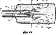
従来のフィルタは、一般に、フィルタのハブ及びフィルタが挿入された血管の長手方向軸線に対して、偏倚した、または傾いた状態になる。その結果、ハブを含めたフィルタ及び取出しフックが、血管壁の長さに沿って該血管壁に係合し、血管内で内皮化するおそれがある。従来技術の図1aに、従来技術のフィルタ113が患者の血管150を通じて送達シース125によって送達されている様子を示す。これが起こった場合、フィルタワイヤの実質的長さに沿って、フィルタが血管内で内皮を増殖させる可能性がより大きくなる。その結果、フィルタは、通常よりも短い期間で永久移植部材となる。Conventional filters are typically biased or tilted with respect to the longitudinal axis of the blood vessel into which the filter hub and filter are inserted. As a result, the filter, including the hub, and the extraction hook may engage the vessel wall along the length of the vessel wall and become endothelialized within the vessel. Prior art FIG. 1 a shows a
さらに、大静脈フィルタの送達または回収に関して、さらなる改善を実施することができる。大静脈フィルタの送達のために、大腿静脈または頸静脈を通じて、導入チューブを有する導入システムを患者の大静脈に経皮的に挿入することができる。導入アセンブリ120の一部を従来技術の図1bに図示する。同図では、従来技術のフィルタ113が患者の頸静脈154を通じて経皮的に送達される。図示のように、折り畳まれた構成のフィルタ113は内側シース122の遠位端121のところに留置され、該フィルタ113のアンカーフック116が遠位端121を通り越して延在している。次いで、アンカーフック116が導入チューブ130を不慮に引掻くもしくは擦るのを避けるために、内側シース122に外挿して外側シース126が配置される。次いで、内側シース122及び外側シース126は、押出部材132とともに導入チューブ130内を移動して、フィルタ113を患者の大静脈へと送達する。フィルタ効果を維持しながら、導入チューブの外壁または血管壁をアンカーフックが不慮に引っ掻く、または擦るのを低減するような特徴を有する大静脈フィルタを設計することは困難であった。Furthermore, further improvements can be implemented with regard to delivery or collection of the vena cava filter. For delivery of the vena cava filter, an introducer system with an introducer tube can be inserted percutaneously into the patient's vena cava through the femoral or jugular vein. A portion of
更に、心臓方向への血栓飛来を阻止する一方で、患者の病状が改善すると損傷を与えずに容易に回収することが可能な、アンカー特徴を備えた取出し可能な大静脈フィルタを提供することもまた、困難である。大静脈フィルタは、実質的に血栓でいっぱいであって、患者が緊張するかバルサルバ法を施されているとき、かなりの力を受けることがある。これによって大静脈は拡張し、大量の血液を心臓に送る傾向がある。このような問題に際し、永久的植込用に設計されたフィルタが外れて心臓に向けて泳動した例がある。Furthermore, it is also possible to provide aremovable vena cava filterwith an anchoring feature that can prevent a thrombus from coming in the direction of the heart, but can be easily recovered without damage when the patient's medical condition improves.It is also difficult . The vena cava filter issubstantially full of thrombus and can be subjected to considerable force when the patient is tense or undergoing Valsalva maneuver. This causes the vena cavato expand and tendto send large amounts of blood to the heart .In such a problem,there is an example in which a filter designed forpermanent implantation isremoved and migratestoward the heart.
例えば、図1cはフィルタ113が拡張状態から回収のために折り畳まれた結果を示している。血流はフィルタ113を心臓に向けて押す傾向があるので、フック113の棘部123が血管壁150の中へより深く食い込む。すると、ストラット138を引っ込めることにより、フック113の棘部123が血管壁150の組織を切り裂くことがある。For example, FIG. 1cshows the result of the
本発明は、血管内の血栓を捕捉するための取出し可能な大静脈フィルタを提供する。このフィルタはその長さ方向に沿って共に取付けられた第1端部を有する複数の一次ストラットを備えている。各ストラットは長さ方向に沿って第1端部からアンカーフックまで延びてストラットの軸線を定めているボディ部材を有している。各ストラットは、血管と係合するための拡張状態と、フィルタの送達または回収のための折畳み状態との間で、長さ方向軸線に対してストラット経路に沿って動くように構成されている。各アンカーフックはストラットの軸線に対して約90度の角度を有している。The present invention provides a removable vena cava filter forcapturing thrombus in blood vessels. The filter includes a plurality of primary struts having first ends attached together along their length. Each strut has a body member extending along a length direction from a first end to ananchor hook and defining a strut axis. Each strut is configured tomove along the strut path relative to the longitudinal axis between an expanded state for engaging a blood vessel and afolded state fordelivery or retrieval of the filter. Eachanchor hook hasan angle ofabout 90 degrees with respect to the strut axis.
他の実施形態では、ボディ部材は弧状部分である。フィルタの回収または送達のため、折畳み状態では、各一次ストラットは、長さ方向軸線に沿って別の一次ストラットと交差して、アンカーフックが占める第2直径よりも大きい第1直径を弧状部分が占めるように、構成されている。拡張状態では、各弧状部分は、長さ方向軸線に沿って弧状に、および第1端部からアンカーフックまで半径方向軸線に対して直線状に延びている。In other embodiments, the body member isan arcuate portion .For folding or delivery of the filter, in the folded state, each primary strut intersects with another primary strut along the longitudinal axis so that the arcuate portion has a first diameter greater than the second diameter occupied by the anchor hook. It is configured tooccupy . In the expanded state,each arcuate portion extends arcuately along the longitudinal axis and linearly with respect to the radial axis from the first end to theanchor hook.
他の実施形態では、取出し可能なフィルタは、長さ方向軸線に沿って共に取付けられた連結端部を有する複数の二次ストラットを備えている。各二次ストラットは、連結端部から延びている第1弧部と、この第1弧部から自由端部まで延びている第2弧部とを有している。第2弧部は、拡張状態のフィルタを血管内で中心に配置するために、血管に係合するように構成されている。In another embodiment,removable filtercomprises a plurality of secondary struts having connected ends attached together along the longitudinal axis. Each secondary strut has a firstarc portion extending from the connecting end portion and a secondarc portion extending from the firstarc portion to the free end portion. The secondarc portion is configured to engage the blood vessel inorder to center theexpanded filter within the blood vessel.
更に他の実施形態では、取出し可能なフィルタは、更に、複数の一次ストラットの第1端部および二次ストラットの連結端部を軸方向に収容するように連結されたハブを有している。更に、フィルタは、血管からフィルタを回収するために複数の一次ストラットと反対側にハブから延びている取出しフックを備えている。In yet another embodiment, the removable filter further comprises a hub connected to axially receive the first ends of the plurality of primary struts and the connecting ends of the secondary struts. The filter further includes anextraction hook extending from the hub opposite the plurality of primary struts forretrieving the filter fromthe blood vessel.
或る実施形態では、二次ストラットの対が一次ストラットの対の間に位置決めされている。二次ストラットの各対は、二次ストラット連結端部の近くで互いに撚られて撚り部分を形成している。二次ストラットの撚り部分は、フィルタが血管内で展開するときにフィルタが傾斜するのを防ぐために、ストラットを効果的に補剛してそれらの中心に位置決めする機能を高めている。従って、ストラットと血管との係合が最小化され、それによりストラットが血管内で内皮化される可能性を減じている。撚り部分の更なる特徴は、二次ストラットが一次ストラットと絡むのを防ぐか、或は少なくとも最小にする点である。In some embodiments,a pair of secondary struts is positioned betweenthe pair of primary struts.Each pair ofsecondary struts is twisted together near thesecondary strut connection end to form a twisted portion. The twisted portions of the secondary struts enhance the ability to effectivelystiffen and position the struts at their centers to prevent the filters from tilting when the filters are deployedin the blood vessel. Thus, the engagement between the strut and the blood vessel is minimized, thereby reducing the possibility that the strut is endothelized within the blood vessel. Further features of the twisted portions can either prevent the secondary struts are involved with the primary struts, or inthat to at least minimize.
本発明の更なる態様、特徴および利点は、添付図面と関連する下記の説明および請求項の考察から明らかになるであろう。Furtheraspects , features and advantages of the present invention will become apparent from a consideration of the following description andclaims taken in conjunctionwith the accompanying drawings.
本発明の一実施形態によれば、図2は、腸骨静脈54、56を通って心臓に向けて流れて肺動脈に入る血液により移送される血栓を溶解させるか捕捉する目的で大静脈50に植え込まれる大静脈フィルタ10を示している。図示のように、腸骨静脈54、56は接合部58のところで大静脈50に合流する。腎臓62からの腎臓静脈60は接合部58のところで大静脈50に合流している。接合部58と腎臓静脈60との間の大静脈50の一部は、大静脈フィルタ10が大腿静脈を通して経皮的に留置される下大静脈52を構成している。好ましくは、大静脈フィルタ10の長さは下大静脈52より短い。フィルタの下部分が腸骨静脈中へ及んでいる場合、フィルタの有効性が損なわれることになり、フィルタワイヤが腎臓静脈の起点に交差する場合、フィルタワイヤは腎臓からの血流に干渉することがある。In accordance with one embodiment of the present invention, FIG. 2 shows the
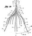
フィルタ10が示されている図3ないし図9を参照して、本発明のこの実施形態を更に論述する。図3aは、各々がハブ11から出ている第1端部を有する4つの一次ストラット12を備えている拡張状態にあるフィルタ10を示している。ハブ11は、図3aに示されるようにフィルタの中央または長さ方向の軸線Xを定めるように、中心点Aのところで一次ストラット12の第1端部14をクリンピングによりコンパクトな束にしている。ハブ11はストラットを形成するために使用されるワイヤのサイズの最小の直径を有している。This embodiment of the present invention will be further discussed with reference to FIGS. 3-9 where the
好ましくは、一次ストラット12は、自己開放式または自己拡張式フィルタとなるような超弾性材料、ステンレス鋼ワイヤ、コバルト−クロム−ニッケル−モリブデン−鉄合金、ニチノール、チタン、コバルト−クロム合金、熱硬化性および熱可塑性のポリマーまたは任意の他の適当な材料で形成されている。この実施形態では、一次ストラット12は、好ましくは、少なくとも約0.038cm(0.015インチ)の直径で丸いまたはほぼ丸い横断面を有するワイヤから形成されている。もちろん、一次ストラットが丸い横断面を有することは必ずしも必要でない。例えば、一次ストラット12は血液の非乱流を維持するために丸い縁部を有する任意の形状をとることができる。Preferably, the
各一次ストラット12はボディ部材15を有している。この実施形態では、ボディ部材15は拡張状態で緩やかなS字形状を有する弧状部分16である。各弧状部分16には、フィルタ10の長さ方向または中央の軸線Xから離れる方向に緩やかに曲がるように構成されている第1湾曲部分20と、フィルタ10の長さ方向の軸線に向けて緩やかに曲がるように構成されている第2湾曲部分23とが形成されている。各弧状部分16の緩やかな曲がりに因り、一次ストラット12上の突出部または屈曲点が実質的に回避されて血管壁に損傷を与えずに係合するのを助ける。Each
図3aおよび図3bに示すように、各一次ストラット12は棘部29を有するアンカーフック26のところで終端し、各一次ストラットのストラット軸線Sを定めている。アンカーフック26は、フィルタ10が血管内の送達位置で展開すると、血管壁内に錨着する。各一次ストラット12はアンカーフック26を血管と係合させるための拡張位置と、フィルタの回収または送達のための折畳み状態との間でストラット経路Pに沿って動くように構成されている。この実施形態では、ストラット経路はフィルタの長さ方向軸線から約20°と40°との間にある。As shown in FIGS. 3a and 3b, each
拡張状態では、各弧状部分16は(図3aに示されるように)長さ方向軸線Xに沿って弧状に、および(図8aに示されるように)半径方向軸線Rに対して直線状に、第1端部14からアンカーフック26まで延びる。図8aに示されるように一次ストラット12は第1端部14から半径方向に延びて半径方向軸線Rを定めている。この実施形態では、一次ストラット12は半径方向軸線Rに対して直線状に延び、他のストラットとの絡まりを回避している。In the expanded state, each
以下により詳細に論述するように、各弧状部分16の緩やかな曲がり部は、折畳み状態で、各一次ストラット12を長さ方向軸線Xに沿って他の一次ストラット12と交差させ、各アンカーフック26が内側に向くか、長さ方向軸線Xに沿って配置されるようにし、回収または送達の際にフィルタが血管壁から離れるようにする。As will be discussed in more detail below,the gentle bends in each
この実施形態では、各アンカーフック26は、弧状部分16から、ストラット経路Pに沿って棘部29まで延び、ストラット経路P上の接点Tのあたりまで伸張している。フック26はストラット軸線Sに対して約90度までの角度を有する曲り部31を有している。フック26がストラット経路P上の接点Tのあたりまで延びるようにフック26を形成する曲り部31を形成することにより、組織を血管壁から実質的に除去することなく、損傷を与えずに各フック26を血管壁から引き込むことができることがわかった。これを達成するために、フック26の弧状または曲り部31がストラット軸線Sから90度に制限されることもわかった。フックまたは棘箇所はストラット経路と一致するかぎり、この原理をいずれのフィルタ設計にも適用することができることを理解すべきである。図示のように、各フック26はフィルタ10の長さ方向軸線とほぼ平行である切返し部を持つ端面33を有している。In this embodiment, each
アンカーフック26は、フィルタを必要とする患者の症状が改善すると、大静脈からフィルタを容易に、損傷を与えずに回収できるように設計されている。同時に、アンカーフック26は、フィルタ10が配置された血管内の送達位置から移動しないようにする。フィルタ10が血管内で展開されると、アンカーフック26は血管内にフィルタを固定するために血管壁に係合して第1軸方向部分を画定する。The
一次ストラット12は、フィルタ10が大きく拡張したときフィルタ10が約25mmと45mmとの間の直径と、約3cmと7cmとの間の長さとを有するように成形され且つ寸法決めされている。例えば、フィルタ10は、大きく展開したとき約35mmの直径および約5cmの長さを有してもよい。一次ストラット12は、フィルタが展開したときアンカーフック26が血管壁の中へ錨着するのに十分なばね強度を有している。The
この実施形態では、フィルタ10は、やはりハブ11から出ている連結端部32を有する複数の二次ストラット30を備えている。ハブ11は二次ストラット30の中心点Aのところの連結端部32を一次ストラットと共にクリンピングにより取付けている。この実施形態では、各一次ストラット12はこれと並置関係で2つの二次ストラットを有している。二次ストラット30は、血管内で拡張状態のフィルタ10を中心に位置決めするために連結端部32から自由端部34まで延びている。図示のように、各二次ストラット30は、アンカーフック26を血管と係合させるために長さ方向軸線に沿って弧状に、および半径方向軸線に対して直線状に連結端部32から自由端部34まで延びている。一次ストラット12と同様に、二次ストラット12は半径方向軸線に対して直線状に延びていて、他のストラットとの絡まりを回避している。In this embodiment, the
二次ストラット30は一次ストラット12と同じ種類の材料から製造されてもよい。しかしながら、二次ストラット30は一次ストラット12より小さい直径、例えば、少なくとも約0.031cm(0.012インチ)の直径を有していてもよい。この実施形態では、二次ストラット30の各々は第1弧部40および第2弧部42で構成されている。第1弧部40は長さ方向軸線Xから離れる方向に連結端部32から延びている。第2弧部42は長さ方向軸線Xに向かって第1弧部40から延びている。図示のように、2つの二次ストラット30はフィルタ10の網状構成の一部を形成するように1つの一次ストラット12の各側に位置決めされている。この実施形態では、ハブ11は、好ましくは、溶接に因る材料における電食または分子交換の可能性を減じるために一次ストラットおよび二次ストラットと同じ材料で製造される。The
大きく展開したとき、二次ストラット30の自由端部34は約25mmないし45mmの直径まで半径方向外方に延びて血管壁に係合する。例えば、二次ストラット30の直径は約35mmから45mmまでの間、半径方向外方に延びてもよい。自由端部34の第2弧部42は血管壁に係合して血管壁が係合される第2軸方向部分を構成する。二次ストラット30は、フィルタ10が展開されている血管のほぼ中心にフィルタ10を安定させる機能がある。その結果、フィルタ10は血管の壁部に長さ方向に係合するストラットの2つの層または部分を有する。フィルタ10の長さは、好ましくは、一次ストラット12の長さにより定められる。更に、ハブ11の直径は一次ストラット12および二次ストラット30を収容した束のサイズにより定められる。この実施形態では、各二次ストラット30の減少直径に因り、最小限8つの二次ストラット30がハブ11の直径またはフィルタ10の全長に加わっている。これは、フィルタ10を血管に対して中心に位置決めされた姿勢に維持しながら達成され、フィルタの網状構成の一部として形成される。図示のように、取出しフック46が一次および二次ストラット12、30の反対側にハブ11から延びている。Greaterwhen deployed, it engages thevessel wall extending radially outwardly to a diameter of the secondary
この実施形態では、各弧状部分16は少なくとも約0.038cm(0.015インチ)の厚さおよび約285000ポンド/平方インチ(psi)と330000psiとの間の引張り強度を有している。各アンカーフック26は、弧状部分16と一体であり、弧状部分の厚さおよび引張り強度を有している。各二次ストラット30は少なくとも約0.031cm(0.012インチ)の厚さおよび約285000psiと330000psiとの間の引張り強度を有している。In this embodiment, each
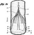
図3cは送達または回収のための送達/回収チューブ94内に配置された折畳み状態のフィルタ10を示している。図示のように、フィルタ10は、各一次ストラット12が長さ方向軸線Xに沿って他の一次ストラット12と交差するように成形されている。その結果、折畳み状態では、アンカーフック26は、フィルタ10の回収および送達のために血管の壁部から離れる方向に長さ方向軸Xに沿って反転する、内方に向く、或いは位置決めされるように構成されている。アンカーフック26のこの反転または内向きの構成により、フィルタ10の送達および回収が簡易化される。例えば、折畳み状態のアンカーフック26が、送達/回収チューブの内壁を削り取る、引っ掻く、または裂くといった懸念が排除される。何故なら、本発明のフィルタ10は、アンカーフック26が血管から離れる方向に長さ方向に沿って内方に向いたり、或いは位置決めされたりするように成形されているからである。実際、頸静脈を通してのフィルタ10の送達または回収中には、1組の内側および外側送達/回収シース(従来技術の図1b参照)が省かれてもよい。むしろ、本発明のフィルタ10を送達或いは回収するために、ループスネア機構を有する送達/回収チューブを1つだけ使用してもよい。FIG. 3c shows the
しかも、折畳み状態では、各一次ストラット12は、弧状部分16、第1湾曲部分20または第2湾曲部分23が第1直径D1を占めるように長さ方向軸線Xに沿って他の一次ストラット12と交差するように構成されている。この実施形態では、第1直径はフィルタの回収または送達のためにアンカーフック26により占められる第2直径D2より大きい。弧状部分16の第1直径は回収経路を広げ、患者からフィルタ10を回収する際、シースまたは血管からアンカーフック26に作用する半径方向の力を減少させることがわかった。アンカーフック26に対する半径方向の力の減少は、患者からのフィルタ10を回収中、アンカーフック26がシースの内壁を削り取る、引っ掻く、または裂くことなどを防ぐ助けとなる。
本発明のこの実施形態では、フィルタ10が任意適当な導入(送達または回収)チューブにより送出または回収されうることを理解されたい。しかしながら、導入チューブが約4.5フレンチと16フレンチとの間、より好ましくは、約6.5フレンチと14フレンチとの間の内径を有するのが好ましい。Moreover, in thefolded state, each
In this embodiment of the present invention,it is to be understood that the
図4は長さ方向軸線Xから半径方向に外方に延びている遠位曲がり部43が形成されている一次ストラット12を示している。図4に示されるように、遠位曲がり部43は約0.5度と2度との間、好ましくは1.0度の角度Gで外方に延びてもよい。この遠位曲がり部43により、フィルタ10は、送達または回収のため折畳み機能を維持しながら、可能である他の方法よりも血管の小さい内径で血栓を効果的にフィルタし得る。FIG. 4 shows the
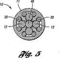
図5はハブ11のところの図3aのフィルタ10の横断面図を示している。図示のように、ハブ11は4つの一次ストラット12の第1端部14と二次ストラット30の連結端部32よりなる束を収容している。更に、図5は一次および二次ストラット12、30の構成を示している。この実施形態では、一次ストラット12は2つの二次ストラット30の間で離間して配置される。もちろん、一次ストラット12は本発明の範囲または精神を超えることなしに任意の他の適当な所望の数の二次ストラット30の間で離間して配置されてもよい。FIG. 5 shows a cross-sectional view of the
この実施形態では、図6aおよび6bは共に下大静脈52内に部分的に展開したフィルタ10を示している。図6aではフィルタ10が患者の大腿静脈を通して送達チューブ48により送出されており、図6bではフィルタ10が患者の頸静脈を通して送達チューブ50により送出されている。フィルタ10の展開のために、送達チューブを、その遠位端部が展開位置にあるように、患者の血管に経皮的に挿通する。この実施形態では、送達チューブを展開位置まで案内するために、好ましくは、ワイヤガイドが使用される。図6aでは、患者の大腿静脈を経る送達のために、取出しフック46が先行し、且つ一次ストラット12のアンカーフック26をフィルタ保持部材により保持した状態で、フィルタ10が送達チューブ48の近位端部に挿通されている。In this embodiment, FIGS. 6 a and 6 b both showthe
図6bでは、患者の頸静脈を経る送達のために、一次ストラット12のアンカーフック26が先導し取出しフック46が後続する状態で、フィルタ10が送達チューブ50の近位端部に挿通されている。この実施形態では、遠位端部にプッシャ部材を有するプッシャワイヤが送達チューブ50の近位端部を通して送られてもよく、それによりフィルタ10が送達チューブ50の遠位端部に達するまで押され、所望位置に送られる。In 6b, the fordelivery through the jugular vein of a patient, in a statewhere the anchor hooks 26 of the primary struts 12will follow the
展開中、二次ストラット30は拡張して、まず血管内でフィルタを中心に位置決めするか或いは均衡化させる。二次ストラットの自由端部が送達チューブ48または50の遠位端部から出ると、二次ストラット30は図6aおよび6bに示されるように拡張位置まで拡張する。第2弧部42は血管の内壁と係合する。二次ストラット30の第2弧部42は血管の中心あたりにフィルタ10の姿勢を安定化させるように機能する。頸静脈を通して送出すると(図6b)、次いでフィルタ10が十分に展開されるまでプッシャワイヤ(図示せず)によりフィルタ10を更に押し込む。During deployment, the
フィルタ10が大静脈内で十分に展開されると、一次ストラット12のアンカーフック26および二次ストラット30の第2弧部42が血管と係合した状態になる。一次ストラット12のアンカーフック26はフィルタ10を血管内の展開位置に錨着して、フィルタ10が血液の流れと共に血管を通って移動するのを防ぐ。その結果、フィルタ10はその長さに沿って軸方向に離間している2組のストラットにより支持される。When the
図7aは下大静脈52内で展開した後に十分に拡張したフィルタ10を示しており、下大静脈52は、フィルタ10を見ることができるように切り欠かれている。血液の流れBFの方向は図7にBFと付された矢印で示されている。一次ストラット12の端部のところのアンカーフック26は下大静脈52の内皮に錨着されているものとして示されている。アンカーフック26は、上記で説明し、図3aないし3cに示すように、本実施形態では、フィルタのハブ11に向けて突出している棘部29を有している。これらの棘部29はフィルタ10を展開位置に保持するように機能する。Figure 7ashows a
更に、一次ストラット12のばね付勢式構成により、アンカーフック26が血管壁に係合し、フィルタを展開位置に錨着することができる。初めの展開後、フィルタ10に作用する血流の圧力は下大静脈52の内皮に錨着した棘部29を維持するのに寄与する。図7aでわかるように、二次ストラット30の第2弧部42もまた血管壁に係合するようにばね付勢式構成を有している。Further, the springbiased configuration of the
図7aでわかるように、ハブ11および取出しフック46はアンカーフック26が血管内に錨着される位置から下流に位置決めされる。血栓は、ストラット12、30により捕捉されると、フィルタ内に留まっている。続いて、フィルタ10を血栓とともに大静脈から経皮的に取り出すことができる。フィルタ10を取り出す場合、好ましくは、初めに取出しフック46の方向に大静脈に経皮的に導入される回収器具により、取出しフック46を把持する。As can be seen in FIG. 7a, the
図7bは血管壁52に係合されたフック26の棘部29と、血管壁から引っ込められた直後の棘部29(仮想図)とを示している。図3aないし図3cで論述したように、棘部29は、血管壁52から組織を剥がし取るなどの損傷を与えずストラットを回収させる。更に、図示のように棘部29は血液の流れBFの方向に向けられ、フィルタ10が血栓とフィルタ10を心臓に向けて泳動させる傾向がある力とを受けたとき、フック26は血管壁組織により強く係合して泳動抵抗を増強する傾向がある。FIG. 7b shows the
一次および二次ストラットは形状記憶合金のような、自己開放式または自己拡張式フィルタとなる任意の適当な材料から形成されてもよい。形状記憶合金は、転移温度以上に加熱されると、剛性になる、すなわち、記憶された状態に戻る所望の特性を有している。本発明に適した形状記憶合金はNi−Tiであって、一般にニチノールという名前で市販されている。この材料を転移温度以上に加熱すると、材料は、その記憶された状態に戻るように、マルテンサイトからオーステナイトへ相変態する。転移温度は合金化元素Ni、Tiの相対割合と、合金化添加剤の任意の包含とに依存している。The primary and secondary strutsmay be formed from any suitable materialthat will be a self-opening or self-expanding filter, such as a shape memory alloy. Shape memory alloys have the desired properties of becoming rigid when heated above the transition temperature, ie, returning to a memorized state. Shape memory alloy suitablefor the present inventionis a Ni-Ti, which is commercially available under the name generally Nitinol. When this material is heated above its transition temperature, the materialundergoes a phase transformation from martensite to austenite so that it returns to its memorized state. The transition temperature depends on the relativeproportions of the alloying elements Ni, Ti and the optional inclusion of alloying additives.
他の実施形態では、一次ストラットおよび二次ストラットの両方はヒトの通常体温の約37℃(98.6°F)よりわずかに低い転移温度を有するニチノールから製造されている。かくして、フィルタを大静脈内で展開して通常体温にさらすと、ストラットの合金はオーステナイト、すなわち、記憶された状態へ変態し、この記憶された状態は、フィルタが血管内で展開されるときの拡張構成である。フィルタを取り出すには、フィルタを冷却して材料をオーステナイトより延性であるマルテンサイトへ変態させてストラットをよりマレアブルにする。このように、フィルタは、より容易に折り畳んで、シースに引き入れて回収することができる。In other embodiments, both the primary struts and secondary struts are made from Nitinol with a slightly lower transition temperaturebelow about 37 ℃ (98.6 ° F)of the normal human body temperature. Thus, when the filter is deployedin the vena cava and exposedto normal body temperature , the strut alloytransforms to austenite, a memorized state, which is the state when the filter is deployed in the blood vessel. Extended configuration. To remove the filter, the filter is cooled totransform the material into martensite, which is more ductile than austenite, making the struts moremalleable . In this way, thefilter can be folded more easily and pulled into the sheath for recovery .
或る実施形態では、一次ストラットおよび二次ストラットの両方はヒトの通常体温の約37℃(98.6°F)よりわずかに高い転移温度を有するニチノールから製造されている。かくして、フィルタを大静脈内で展開し通常体温にさらすと、ストラットはマルテンサイト状態にあるので所望の形状に、つまり本発明では拡張時の形状に、屈曲または形成するのに十分な延性を有している。フィルタ20を取り出すには、フィルタ20を加熱して合金をオーステナイトへ変態させ、フィルタを剛性にして、折畳み時の形状である記憶された状態に戻るようにする。In certain embodiments, both primary and secondary struts are made from nitinol, which has a transition temperature slightlyabovethe normal body temperature of about 37 ° C. (98.6 ° F.). Thus, when the filter is deployed in the vena cava and exposed tonormal body temperature , the struts are in the martensite state andtherefore have sufficient ductility to bend or form into the desired shape, i.e., the expanded shape in the present invention. Is doing . To retrieve the
図7cに示す他の実施形態では、血管壁52に係合するフック127の棘部129と、血管壁から引っ込められた直後の棘部129(仮想図)とを示している。図示のように、フック126は凹形切返し部を有する端面133まで延びている。この実施形態では、端面133は凹形端部を形成するように研削により形成されている。フック126は、ストラット経路P上の接点Tのあたりまで、ストラット経路Pに沿って延びている。フック126はストラット軸線Sに対して約90°までの角度を持つ曲り部131を有している。棘部129は、さらに、心臓と逆方向にフィルタが泳動するのを阻止するように形成されている。中空または凹形の端部により、棘部129の鋭さを増して血管壁に与える損傷の可能性を少なくしている。In another embodimentshown in FIG. 7c, a
更に他の実施形態では、図7dは血管壁252に係合されたフック226の棘部229と、血管壁から引っ込められた直後の棘部229(仮想図)とを示している。図示のように、フック226は図7bに示された実施形態より更に延びている。フック226の長さを延長することにより、血管壁への係合の深さを増大することができる。しかしながら、フック226はストラット経路P上の接点Tのあたりまでストラット経路Pに沿って延びている。フック226はストラット軸線Sに対して約90°までの角度を持つ曲り部231を有している。図示のように、ストラットが血管壁から損傷を与えず抜き出されるように、まっすぐな延長部分235が経路Pの接点Tと実質的に平行である。図3bに示された実施形態におけるように、各フック226はフィルタの長さ方向軸線とほぼ平行である切返し部を持つ端面233を有している。In yet another embodiment, FIG. 7d shows the
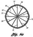
図8aは半径方向Rに対して一次ストラット12、二次ストラット30およびハブ11により構成された網状構成またはパターンを示している。図8aに示される網状パターンは肺塞栓の可能性を防ぐために心臓および肺に達する前に血流で運ばれる血栓を捕捉するように機能する。この網状パターンは患者の血管系内を運ばれることが望ましくないサイズの血栓を捕捉して止めるように寸法決めされている。ハブは小型化されているため、血流に対する抵抗が最小限になる。FIG. 8 a shows a reticulated configuration or pattern constituted by
図8aは、一次ストラットと二次ストラットが実質的に均等な角度で互いに離間する網状パターンを示している。この網状パターンは一次ストラットと二次ストラットとの間で一様に血流を流通させて血栓を捕捉する可能性を高めている。しかしながら、図8bに示すように、一次ストラット312および二次ストラット330の組は、それぞれが個別に、半径方向軸線R'に対する割合が実質的に等しくなるように離間して配置されてもよいことを理解すべきである。例えば、二次ストラット330と他の二次ストラット330の間は等間隔であってもよいし、一次ストラット312と他の一次ストラット312の間は等間隔であってもよい。その結果、本実施形態の網状パターンは、大静脈の(線8−8に沿った)横断面図に示すように、一次ストラット312および二次ストラット330の間で不規則または不均等な間隔を有することになる。FIG. 8ashows a reticulated pattern in which primary and secondary struts are spaced from each other at substantially equal angles . The mesh pattern is to enhance the likelihood ofcapturing thrombiby circulating blood flow uniformly between the primary struts and secondary struts. However, as shown in FIG. 8b,the sets of
図9aおよび図9bは下大静脈52からフィルタ10を取出す手順に使用されている回収装置65の一部を示している。この回収装置65は頸静脈を経て上大静脈に経皮的に導入される。この手順では、回収装置65の回収カテーテルまたはシース68を上大静脈に挿入する。遠位端部にループスネア72を有するワイヤ70を回収シース68に通し、そしてシース68の遠位端部から出す。次いで、ループスネア72がフィルタ10の取出しフック46を捕捉するように、任意の適当な手段により回収装置の近位端部からワイヤ70を操作する。シース68を押しながらワイヤ70を引く反対牽引法によって、シース68をフィルタ10に外挿させる。シース68がフィルタ10に外挿されると、一次ストラット12、次いで二次ストラット30はシース68の縁部に係合し、フィルタの長さ方向軸線に向けてハブ11のところで回動するか、或いは曲げ撓みを受ける。長さ方向軸線に向かう回動により、ストラット12および30の端部を血管壁から引っ込める。このようにして、回収手順において血管壁に表面損傷74および小さい点損傷76のみが生じる。図示のように、表面損傷74は二次ストラット30の端部により生じ、小さい点損傷76は一次ストラット12のアンカーフック26により生じる。しかしながら、フィルタを患者から回収する他の任意適当な手順を実施してもよいことを理解されたい。FIGS. 9 a and 9 b show a portion of the collection device 65 used in the procedure for removing the
この装置の実施形態を、丸い横断面を有するワイヤから構成されたものとして開示したが、この装置は、レーザー切断、放電機械加工または任意の他の適当な方法により適当な材料のチューブから切断されてもよい。The embodiments of the device have been disclosed as being constructed from wire having a round cross-section, this apparatus, laser cutting,is cut from atube of suitable material by electrical discharge machining or any other suitable methodMay be .
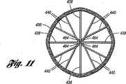
図10および図11に示される他の実施形態では、フィルタ420はハブ442から延びている4つの一次ストラット438および8つの二次ストラット440を有している。各一次ストラット438は棘部454を有するアンカーフック452で終わっている。一次ストラット438は十分なばね強度を有しており、フィルタが大静脈436内で展開すると、アンカーフック452、特に、棘部444を大静脈436の血管壁内に錨着させて、フィルタが送達位置から泳動するのを防ぐ。血流がフィルタに与える圧力によって、大静脈436の内皮に錨着した棘部454はそのまま維持される。In other embodiments shown in FIGS. 10 and 11, the
隣接した一次ストラット438間には、一対の二次ストラット440が位置決めされている。各二次ストラット440はハブ442から延びていて、中央軸線444の方に向いている先端部462で終わっている。これらの先端部462はハブ442と一次ストラット438のアンカーフック454との間に長さ方向に位置決めされている。隣接した一次ストラット間に位置決めされた各対の二次ストラット440の連結端部は撚り合わされて撚り部分464を構成している。A pair of
撚り部分464は二次ストラット440の各対を効果的に補剛しているので、より細い二次ストラットを使用して、フィルタを血管内で中心に位置決めするために適切な均衡化力を提供することができる。撚り部分464のさらなる利点は、二次ストラットが一次ストラットと絡むのを阻止することである。The
二次ストラット440は、一次ストラット438と同じ種類の材料から製造してもよく、一次ストラットを形成するのに使用される同じ方法により形成してもよい。しかしながら、二次ストラットは一次ストラットより小さい直径を有してもよい。撚り部分464を形成するには、隣接した一次ストラット438間に位置決めされた二次ストラットの各対をハブ442に取付けた後、互いに撚り合わせてもよい。各撚り部分464は1つまたはそれ以上の撚りを有する。例えば、各撚り部分464は約10までの撚りを有してもよい。或る実施例においては、各部分における撚りの数は約3つから5つの間でもよい。撚りの数を増やすことにより、一対の互いに撚り合わせられた二次ストラットの剛性が高まる。ハブ442は、好ましくは、電食の可能性を最小にするために一次ストラットおよび二次ストラットと同じ材料で製造されている。The
図11は一次ストラット438、二次ストラット440およびハブ442により構成された網状パターン(「ネット」)を示している。ネットは、血流内を運ばれる血栓を捕捉して、肺塞栓症の原因となりうる血栓が心臓と肺に達するのを阻止する機能がある。ネットは、患者の血管系には望ましくないサイズの血栓を捕捉して止めるように寸法決めされている。図示のように、ストラット438の間は実質的に等間隔である。FIG. 11 shows a reticulated pattern (“net”) composed of
ハブ442およびハブに取付けられた取出しフック466は、アンカーフック452が血管436に錨着される位置の下流に位置決めされる。血栓は、ストラットにより捕捉されるとフィルタ420に留まっており、次いで、フィルタ420が血栓とともに大静脈から経皮的に回収されてもよい。フィルタ420を回収する場合、代表的には、大静脈に経皮的に導入される回収用フックにより取出しフック466を把持する。
本発明を好適な実施形態に関して説明したが、特に前記教示を鑑みて当業者には変更例が行なわれることができるので、本発明が前記実施形態に限定されないことはもちろん理解されるであろう。 While the invention has been described in terms of a preferred embodiment, it will be appreciated that the invention is not limited to the foregoing embodiment, particularly as one skilled in the art can make modifications in light of the above teachings. .
Claims (15)
Translated fromJapanese当該フィルタの長さ方向軸線に沿って一緒にされた第1端部を有する複数の一次ストラットを備えており、各ストラットは、前記長さ方向軸の方向で延びているボディ部材と、該ボディ部材の前記第1端部の反対側の第2端部から延びて該ボディ部材よりも前方位置にある前端面に至るアンカーフックとを有しており、
前記各ストラットは、前記アンカーフックが血管壁と係合するための拡張状態とフィルタ送達または回収のための前記アンカーフックが血管壁から離れる折畳み状態との間で前記長さ方向軸に対し弧状のストラット経路に沿って変位可能で、
前記アンカーフックは、前記ボディ部材と同じ厚さと引張強度を備えるとともに、各アンカーフックは、前記血管の組織を除去せずに前記血管から引き込むことができるように、前記ボディ部材の前記第1端部の反対側の前記第2端部から、前記ストラットが前記折り畳み状態から前記拡張状態に動く方向で、前記ストラットが拡張状態と折り畳み状態との間で変位するときに前記前端面が通る弧状の経路に近づき、該経路に沿って延びている、取出し可能なフィルタ。A removable filter for capturing blood clots in blood vessels,
A plurality of primary struts having first ends joined along the longitudinal axis of the filter, each strutextending in the direction of the longitudinal axis; An anchor hookthatextends from a second end opposite to the first end of the member and reaches a front end surface that is in a forward positionrelative to thebody member ;
Each strut is arcuate relative to the longitudinal axis between an expanded state for the anchor hook to engage thevessel wall and a folded state in which theanchor hook for filter delivery or retrieval isseparated from the vessel wall .Displaceable along the strut path,
Wherein the anchor hook is provided with a same thickness and tensile strength and the body member, each anchor hooks, as can be drawn from the vessel without removing the tissue of the bloodvessel, said first end of said body member An arc-like shape through which the front end surface passes when the strut is displaced between the expanded state and the folded state in the direction in which the strut moves from the folded state to the expanded state from the second end portion on the opposite side of the portion A removable filterapproaching and extending along the path .
Applications Claiming Priority (9)
| Application Number | Priority Date | Filing Date | Title |
|---|---|---|---|
| US56281304P | 2004-04-16 | 2004-04-16 | |
| US56319204P | 2004-04-16 | 2004-04-16 | |
| US56317604P | 2004-04-16 | 2004-04-16 | |
| US56290904P | 2004-04-16 | 2004-04-16 | |
| US60/562,813 | 2004-04-16 | ||
| US60/562,909 | 2004-04-16 | ||
| US60/563,176 | 2004-04-16 | ||
| US60/563,192 | 2004-04-16 | ||
| PCT/US2005/013281WO2005102212A1 (en) | 2004-04-16 | 2005-04-18 | Removable vena cava filter with anchoring feature for reduced trauma |
Publications (3)
| Publication Number | Publication Date |
|---|---|
| JP2007532270A JP2007532270A (en) | 2007-11-15 |
| JP2007532270A5 JP2007532270A5 (en) | 2008-06-26 |
| JP4898986B2true JP4898986B2 (en) | 2012-03-21 |
Family
ID=34966769
Family Applications (1)
| Application Number | Title | Priority Date | Filing Date |
|---|---|---|---|
| JP2007508640AExpired - LifetimeJP4898986B2 (en) | 2004-04-16 | 2005-04-18 | Removable vena cava filter with anchor shape to reduce damage |
Country Status (9)
| Country | Link |
|---|---|
| US (1) | US7972353B2 (en) |
| EP (1) | EP1737385B1 (en) |
| JP (1) | JP4898986B2 (en) |
| AT (1) | ATE491409T1 (en) |
| AU (1) | AU2005235315B2 (en) |
| CA (1) | CA2563372C (en) |
| DE (1) | DE602005025329D1 (en) |
| DK (1) | DK1737385T3 (en) |
| WO (1) | WO2005102212A1 (en) |
Families Citing this family (95)
| Publication number | Priority date | Publication date | Assignee | Title |
|---|---|---|---|---|
| US7314477B1 (en) | 1998-09-25 | 2008-01-01 | C.R. Bard Inc. | Removable embolus blood clot filter and filter delivery unit |
| US9204956B2 (en) | 2002-02-20 | 2015-12-08 | C. R. Bard, Inc. | IVC filter with translating hooks |
| US8162972B2 (en) | 2004-01-22 | 2012-04-24 | Rex Medical, Lp | Vein filter |
| US8500774B2 (en) | 2004-01-22 | 2013-08-06 | Rex Medical, L.P. | Vein filter |
| US9510929B2 (en) | 2004-01-22 | 2016-12-06 | Argon Medical Devices, Inc. | Vein filter |
| US8211140B2 (en) | 2004-01-22 | 2012-07-03 | Rex Medical, L.P. | Vein filter |
| US7338512B2 (en) | 2004-01-22 | 2008-03-04 | Rex Medical, L.P. | Vein filter |
| US7704266B2 (en) | 2004-01-22 | 2010-04-27 | Rex Medical, L.P. | Vein filter |
| US8062326B2 (en) | 2004-01-22 | 2011-11-22 | Rex Medical, L.P. | Vein filter |
| US7976562B2 (en) | 2004-01-22 | 2011-07-12 | Rex Medical, L.P. | Method of removing a vein filter |
| US8105349B2 (en) | 2004-04-16 | 2012-01-31 | Cook Medical Technologies Llc | Removable vena cava filter having primary struts for enhanced retrieval and delivery |
| US7699867B2 (en) | 2004-04-16 | 2010-04-20 | Cook Incorporated | Removable vena cava filter for reduced trauma in collapsed configuration |
| US8043322B2 (en) | 2004-04-16 | 2011-10-25 | Cook Medical Technologies Llc | Removable vena cava filter having inwardly positioned anchoring hooks in collapsed configuration |
| US7625390B2 (en)* | 2004-04-16 | 2009-12-01 | Cook Incorporated | Removable vena cava filter |
| CA2563372C (en) | 2004-04-16 | 2012-08-07 | Cook, Inc. | Removable vena cava filter with anchoring feature for reduced trauma |
| US7704267B2 (en) | 2004-08-04 | 2010-04-27 | C. R. Bard, Inc. | Non-entangling vena cava filter |
| ES2444590T3 (en) | 2004-09-27 | 2014-02-25 | Rex Medical, L.P. | Venous filter |
| ATE516772T1 (en) | 2004-09-27 | 2011-08-15 | Cook Inc | REMOVABLE VENA CAVA FILTER |
| EP1814488A1 (en)* | 2004-11-08 | 2007-08-08 | Cook Incorporated | Blood clot filter configured for a wire guide |
| CA2607580C (en) | 2005-05-12 | 2016-12-20 | C.R. Bard Inc. | Removable embolus blood clot filter |
| US8613754B2 (en) | 2005-05-12 | 2013-12-24 | C. R. Bard, Inc. | Tubular filter |
| US12115057B2 (en) | 2005-05-12 | 2024-10-15 | C.R. Bard, Inc. | Tubular filter |
| WO2007021340A1 (en) | 2005-08-09 | 2007-02-22 | C.R. Bard Inc | Embolus blood clot filter and delivery system |
| US9131999B2 (en) | 2005-11-18 | 2015-09-15 | C.R. Bard Inc. | Vena cava filter with filament |
| WO2007133366A2 (en) | 2006-05-02 | 2007-11-22 | C. R. Bard, Inc. | Vena cava filter formed from a sheet |
| US9326842B2 (en) | 2006-06-05 | 2016-05-03 | C. R . Bard, Inc. | Embolus blood clot filter utilizable with a single delivery system or a single retrieval system in one of a femoral or jugular access |
| US9867530B2 (en) | 2006-08-14 | 2018-01-16 | Volcano Corporation | Telescopic side port catheter device with imaging system and method for accessing side branch occlusions |
| US10076401B2 (en) | 2006-08-29 | 2018-09-18 | Argon Medical Devices, Inc. | Vein filter |
| US8795351B2 (en) | 2007-04-13 | 2014-08-05 | C.R. Bard, Inc. | Migration resistant embolic filter |
| WO2009009802A1 (en) | 2007-07-12 | 2009-01-15 | Volcano Corporation | Oct-ivus catheter for concurrent luminal imaging |
| EP2178442B1 (en) | 2007-07-12 | 2017-09-06 | Volcano Corporation | Catheter for in vivo imaging |
| US9596993B2 (en) | 2007-07-12 | 2017-03-21 | Volcano Corporation | Automatic calibration systems and methods of use |
| WO2009032834A1 (en) | 2007-09-07 | 2009-03-12 | Crusader Medical Llc | Percutaneous permanent retrievable vascular filter |
| US8795318B2 (en) | 2007-09-07 | 2014-08-05 | Merit Medical Systems, Inc. | Percutaneous retrievable vascular filter |
| US8246672B2 (en) | 2007-12-27 | 2012-08-21 | Cook Medical Technologies Llc | Endovascular graft with separately positionable and removable frame units |
| WO2010025379A1 (en)* | 2008-08-29 | 2010-03-04 | Cook Incorporated | Vena cava filter having plurality of hooks |
| US8246648B2 (en) | 2008-11-10 | 2012-08-21 | Cook Medical Technologies Llc | Removable vena cava filter with improved leg |
| EP2523629B1 (en)* | 2010-01-12 | 2021-04-14 | Cook Medical Technologies LLC | Visual stabilizer on anchor legs of vena cava filter |
| US11141063B2 (en) | 2010-12-23 | 2021-10-12 | Philips Image Guided Therapy Corporation | Integrated system architectures and methods of use |
| US11040140B2 (en) | 2010-12-31 | 2021-06-22 | Philips Image Guided Therapy Corporation | Deep vein thrombosis therapeutic methods |
| US10022212B2 (en) | 2011-01-13 | 2018-07-17 | Cook Medical Technologies Llc | Temporary venous filter with anti-coagulant delivery method |
| US8734480B2 (en) | 2011-08-05 | 2014-05-27 | Merit Medical Systems, Inc. | Vascular filter |
| US8740931B2 (en) | 2011-08-05 | 2014-06-03 | Merit Medical Systems, Inc. | Vascular filter |
| US9360630B2 (en) | 2011-08-31 | 2016-06-07 | Volcano Corporation | Optical-electrical rotary joint and methods of use |
| US8702747B2 (en) | 2011-10-21 | 2014-04-22 | Cook Medical Technologies Llc | Femoral removal vena cava filter |
| EP2816969B1 (en) | 2012-02-23 | 2018-06-13 | Merit Medical Systems, Inc. | Vascular filter |
| CA2887421A1 (en) | 2012-10-05 | 2014-04-10 | David Welford | Systems and methods for amplifying light |
| US9324141B2 (en) | 2012-10-05 | 2016-04-26 | Volcano Corporation | Removal of A-scan streaking artifact |
| US10568586B2 (en) | 2012-10-05 | 2020-02-25 | Volcano Corporation | Systems for indicating parameters in an imaging data set and methods of use |
| US11272845B2 (en) | 2012-10-05 | 2022-03-15 | Philips Image Guided Therapy Corporation | System and method for instant and automatic border detection |
| US20140100454A1 (en) | 2012-10-05 | 2014-04-10 | Volcano Corporation | Methods and systems for establishing parameters for three-dimensional imaging |
| US9858668B2 (en) | 2012-10-05 | 2018-01-02 | Volcano Corporation | Guidewire artifact removal in images |
| US9292918B2 (en) | 2012-10-05 | 2016-03-22 | Volcano Corporation | Methods and systems for transforming luminal images |
| US9367965B2 (en) | 2012-10-05 | 2016-06-14 | Volcano Corporation | Systems and methods for generating images of tissue |
| US9286673B2 (en) | 2012-10-05 | 2016-03-15 | Volcano Corporation | Systems for correcting distortions in a medical image and methods of use thereof |
| US9307926B2 (en) | 2012-10-05 | 2016-04-12 | Volcano Corporation | Automatic stent detection |
| US10070827B2 (en) | 2012-10-05 | 2018-09-11 | Volcano Corporation | Automatic image playback |
| US9840734B2 (en) | 2012-10-22 | 2017-12-12 | Raindance Technologies, Inc. | Methods for analyzing DNA |
| EP2931132B1 (en) | 2012-12-13 | 2023-07-05 | Philips Image Guided Therapy Corporation | System for targeted cannulation |
| US10939826B2 (en) | 2012-12-20 | 2021-03-09 | Philips Image Guided Therapy Corporation | Aspirating and removing biological material |
| US11406498B2 (en) | 2012-12-20 | 2022-08-09 | Philips Image Guided Therapy Corporation | Implant delivery system and implants |
| WO2014113188A2 (en) | 2012-12-20 | 2014-07-24 | Jeremy Stigall | Locating intravascular images |
| EP2934311B1 (en) | 2012-12-20 | 2020-04-15 | Volcano Corporation | Smooth transition catheters |
| US10942022B2 (en) | 2012-12-20 | 2021-03-09 | Philips Image Guided Therapy Corporation | Manual calibration of imaging system |
| EP2934310A4 (en) | 2012-12-20 | 2016-10-12 | Nathaniel J Kemp | Optical coherence tomography system that is reconfigurable between different imaging modes |
| JP2016507892A (en) | 2012-12-21 | 2016-03-10 | デイビッド ウェルフォード, | System and method for narrowing the wavelength emission of light |
| US10413317B2 (en) | 2012-12-21 | 2019-09-17 | Volcano Corporation | System and method for catheter steering and operation |
| US9612105B2 (en) | 2012-12-21 | 2017-04-04 | Volcano Corporation | Polarization sensitive optical coherence tomography system |
| US9486143B2 (en) | 2012-12-21 | 2016-11-08 | Volcano Corporation | Intravascular forward imaging device |
| US10332228B2 (en) | 2012-12-21 | 2019-06-25 | Volcano Corporation | System and method for graphical processing of medical data |
| EP2936241B1 (en) | 2012-12-21 | 2020-10-21 | Nathaniel J. Kemp | Power-efficient optical buffering using a polarisation-maintaining active optical switch |
| JP2016501625A (en) | 2012-12-21 | 2016-01-21 | ジェローム マイ, | Ultrasound imaging with variable line density |
| US10058284B2 (en) | 2012-12-21 | 2018-08-28 | Volcano Corporation | Simultaneous imaging, monitoring, and therapy |
| CA2895769A1 (en) | 2012-12-21 | 2014-06-26 | Douglas Meyer | Rotational ultrasound imaging catheter with extended catheter body telescope |
| EP2934323A4 (en) | 2012-12-21 | 2016-08-17 | Andrew Hancock | SYSTEM AND METHOD FOR MULTIPLE PROCESSING OF IMAGE SIGNALS |
| WO2014138555A1 (en) | 2013-03-07 | 2014-09-12 | Bernhard Sturm | Multimodal segmentation in intravascular images |
| US10226597B2 (en) | 2013-03-07 | 2019-03-12 | Volcano Corporation | Guidewire with centering mechanism |
| US20140276923A1 (en) | 2013-03-12 | 2014-09-18 | Volcano Corporation | Vibrating catheter and methods of use |
| EP2967391A4 (en) | 2013-03-12 | 2016-11-02 | Donna Collins | SYSTEMS AND METHODS FOR DIAGNOSING CORONARY MICROVASCULAR DISEASE |
| WO2014159819A1 (en) | 2013-03-13 | 2014-10-02 | Jinhyoung Park | System and methods for producing an image from a rotational intravascular ultrasound device |
| US9301687B2 (en) | 2013-03-13 | 2016-04-05 | Volcano Corporation | System and method for OCT depth calibration |
| US11026591B2 (en) | 2013-03-13 | 2021-06-08 | Philips Image Guided Therapy Corporation | Intravascular pressure sensor calibration |
| US10292677B2 (en) | 2013-03-14 | 2019-05-21 | Volcano Corporation | Endoluminal filter having enhanced echogenic properties |
| US12343198B2 (en) | 2013-03-14 | 2025-07-01 | Philips Image Guided Therapy Corporation | Delivery catheter having imaging capabilities |
| US10219887B2 (en) | 2013-03-14 | 2019-03-05 | Volcano Corporation | Filters with echogenic characteristics |
| US20160030151A1 (en) | 2013-03-14 | 2016-02-04 | Volcano Corporation | Filters with echogenic characteristics |
| EP3030194B1 (en) | 2013-08-09 | 2019-03-13 | Merit Medical Systems, Inc. | Vascular filter delivery systems |
| US10010398B2 (en)* | 2013-10-01 | 2018-07-03 | Cook Medical Technologies Llc | Filter device, system, and method |
| GB2524289B (en)* | 2014-03-19 | 2016-03-09 | Cook Medical Technologies Llc | Vascular filter |
| US10085759B2 (en) | 2014-08-14 | 2018-10-02 | Boston Scientific Scimed, Inc. | Kidney stone suction device |
| US9987028B2 (en) | 2015-02-12 | 2018-06-05 | Cook Medical Technologies Llc | Partially covered braided funnel aspiration catheter |
| CN207821947U (en)* | 2017-04-11 | 2018-09-07 | 杭州唯强医疗科技有限公司 | With from central vena cava filter |
| KR102451052B1 (en)* | 2020-06-26 | 2022-10-05 | 사회복지법인 삼성생명공익재단 | Umbrella type embolic apparatus |
| CN113180880A (en)* | 2021-06-04 | 2021-07-30 | 上海蓝脉医疗科技有限公司 | Filter and medical device |
| CN116196139A (en)* | 2021-11-30 | 2023-06-02 | 上海蓝脉医疗科技有限公司 | a filter |
Family Cites Families (212)
| Publication number | Priority date | Publication date | Assignee | Title |
|---|---|---|---|---|
| US2281448A (en)* | 1941-09-17 | 1942-04-28 | Scully Signal Co | Device for partially obstructing pipes |
| US3174851A (en)* | 1961-12-01 | 1965-03-23 | William J Buehler | Nickel-base alloys |
| US3137298A (en)* | 1963-06-25 | 1964-06-16 | Jacob A Glassman | Surgical extractors |
| US3334629A (en) | 1964-11-09 | 1967-08-08 | Bertram D Cohn | Occlusive device for inferior vena cava |
| US3540431A (en) | 1968-04-04 | 1970-11-17 | Kazi Mobin Uddin | Collapsible filter for fluid flowing in closed passageway |
| US3868956A (en)* | 1972-06-05 | 1975-03-04 | Ralph J Alfidi | Vessel implantable appliance and method of implanting it |
| US3952747A (en)* | 1974-03-28 | 1976-04-27 | Kimmell Jr Garman O | Filter and filter insertion instrument |
| SU835447A1 (en) | 1979-05-16 | 1981-06-07 | Предприятие П/Я А-1882 | Implantation venous filter |
| US4425908A (en)* | 1981-10-22 | 1984-01-17 | Beth Israel Hospital | Blood clot filter |
| SE445884B (en) | 1982-04-30 | 1986-07-28 | Medinvent Sa | DEVICE FOR IMPLANTATION OF A RODFORM PROTECTION |
| US4643184A (en)* | 1982-09-29 | 1987-02-17 | Mobin Uddin Kazi | Embolus trap |
| US4494531A (en)* | 1982-12-06 | 1985-01-22 | Cook, Incorporated | Expandable blood clot filter |
| US5190546A (en)* | 1983-10-14 | 1993-03-02 | Raychem Corporation | Medical devices incorporating SIM alloy elements |
| US4665906A (en)* | 1983-10-14 | 1987-05-19 | Raychem Corporation | Medical devices incorporating sim alloy elements |
| US5067957A (en) | 1983-10-14 | 1991-11-26 | Raychem Corporation | Method of inserting medical devices incorporating SIM alloy elements |
| US6221102B1 (en)* | 1983-12-09 | 2001-04-24 | Endovascular Technologies, Inc. | Intraluminal grafting system |
| US4727873A (en)* | 1984-04-17 | 1988-03-01 | Mobin Uddin Kazi | Embolus trap |
| US4759757A (en) | 1984-04-18 | 1988-07-26 | Corvita Corporation | Cardiovascular graft and method of forming same |
| DE3429850A1 (en) | 1984-05-12 | 1986-02-20 | Ing. Walter Hengst GmbH & Co KG, 4400 Münster | Improved blood filter for insertion into veins |
| DK151404C (en) | 1984-05-23 | 1988-07-18 | Cook Europ Aps William | FULLY FILTER FOR IMPLANTATION IN A PATIENT'S BLOOD |
| US5037377A (en) | 1984-11-28 | 1991-08-06 | Medtronic, Inc. | Means for improving biocompatibility of implants, particularly of vascular grafts |
| FR2573646B1 (en) | 1984-11-29 | 1988-11-25 | Celsa Composants Electr Sa | PERFECTED FILTER, PARTICULARLY FOR THE RETENTION OF BLOOD CLOTS |
| FR2587901A1 (en) | 1985-09-27 | 1987-04-03 | Bocquee Henry | Device intended to stop the circulation of thrombi in vessels |
| SE453258B (en) | 1986-04-21 | 1988-01-25 | Medinvent Sa | ELASTIC, SELF-EXPANDING PROTEST AND PROCEDURE FOR ITS MANUFACTURING |
| US4793348A (en) | 1986-11-15 | 1988-12-27 | Palmaz Julio C | Balloon expandable vena cava filter to prevent migration of lower extremity venous clots into the pulmonary circulation |
| FR2606641B1 (en) | 1986-11-17 | 1991-07-12 | Promed | FILTERING DEVICE FOR BLOOD CLOTS |
| GB2200848B (en) | 1987-02-25 | 1991-02-13 | Mo Med Inst Pirogova | Intravenous filter, and apparatus and method for preoperative preparation thereof |
| US4817600A (en)* | 1987-05-22 | 1989-04-04 | Medi-Tech, Inc. | Implantable filter |
| US4873978A (en) | 1987-12-04 | 1989-10-17 | Robert Ginsburg | Device and method for emboli retrieval |
| FR2632864B2 (en) | 1987-12-31 | 1990-10-19 | Biomat Sarl | ANTI-EMBOLIC ELASTIC FILTERING SYSTEM FOR CELLAR VEIN AND ASSEMBLY OF MEANS FOR ITS PLACEMENT |
| SU1711906A1 (en) | 1988-01-11 | 1992-02-15 | 2-й Московский государственный медицинский институт им.Н.И.Пирогова | Intravenous filter and device for its implantation |
| US4830003A (en)* | 1988-06-17 | 1989-05-16 | Wolff Rodney G | Compressive stent and delivery system |
| FR2632848A1 (en) | 1988-06-21 | 1989-12-22 | Lefebvre Jean Marie | FILTER FOR MEDICAL USE |
| US4832055A (en)* | 1988-07-08 | 1989-05-23 | Palestrant Aubrey M | Mechanically locking blood clot filter |
| US4950227A (en) | 1988-11-07 | 1990-08-21 | Boston Scientific Corporation | Stent delivery system |
| US4856516A (en) | 1989-01-09 | 1989-08-15 | Cordis Corporation | Endovascular stent apparatus and method |
| US5152777A (en) | 1989-01-25 | 1992-10-06 | Uresil Corporation | Device and method for providing protection from emboli and preventing occulsion of blood vessels |
| US4969891A (en) | 1989-03-06 | 1990-11-13 | Gewertz Bruce L | Removable vascular filter |
| FR2649884B1 (en) | 1989-07-18 | 1993-04-30 | Ems Ind | FILTER FOR THE RETENTION OF BLOOD CLOTS |
| US5059205A (en) | 1989-09-07 | 1991-10-22 | Boston Scientific Corporation | Percutaneous anti-migration vena cava filter |
| US5242462A (en)* | 1989-09-07 | 1993-09-07 | Boston Scientific Corp. | Percutaneous anti-migration vena cava filter |
| GB2238485B (en) | 1989-11-28 | 1993-07-14 | Cook William Europ | A collapsible filter for introduction in a blood vessel of a patient |
| FR2655533A1 (en) | 1989-12-13 | 1991-06-14 | Lefebvre Jean Marie | FILTER CATHETER. |
| US5421832A (en)* | 1989-12-13 | 1995-06-06 | Lefebvre; Jean-Marie | Filter-catheter and method of manufacturing same |
| US5135516A (en) | 1989-12-15 | 1992-08-04 | Boston Scientific Corporation | Lubricious antithrombogenic catheters, guidewires and coatings |
| US5304121A (en)* | 1990-12-28 | 1994-04-19 | Boston Scientific Corporation | Drug delivery system making use of a hydrogel polymer coating |
| FR2657261A1 (en)* | 1990-01-19 | 1991-07-26 | Bovyn Gilles | Device for temporary implantation of a blood filter in a vein of the human body |
| FR2660189B1 (en)* | 1990-03-28 | 1992-07-31 | Lefebvre Jean Marie | DEVICE INTENDED TO BE IMPLANTED IN A VESSEL WITH SIDE LEGS WITH ANTAGONIST TEETH. |
| US5071407A (en) | 1990-04-12 | 1991-12-10 | Schneider (U.S.A.) Inc. | Radially expandable fixation member |
| US5221261A (en)* | 1990-04-12 | 1993-06-22 | Schneider (Usa) Inc. | Radially expandable fixation member |
| FR2663217B1 (en) | 1990-06-15 | 1992-10-16 | Antheor | FILTERING DEVICE FOR THE PREVENTION OF EMBOLIES. |
| CA2048307C (en) | 1990-08-14 | 1998-08-18 | Rolf Gunther | Method and apparatus for filtering blood in a blood vessel of a patient |
| US5160342A (en) | 1990-08-16 | 1992-11-03 | Evi Corp. | Endovascular filter and method for use thereof |
| US5108419A (en)* | 1990-08-16 | 1992-04-28 | Evi Corporation | Endovascular filter and method for use thereof |
| US5147379A (en) | 1990-11-26 | 1992-09-15 | Louisiana State University And Agricultural And Mechanical College | Insertion instrument for vena cava filter |
| FR2672487B1 (en) | 1991-02-12 | 1998-09-11 | Guy Caburol | MODULAR SELF-CENTERING VENOUS FILTER IMPLANTABLE ON THE BLOOD PATH. |
| DE69222156T2 (en)* | 1991-03-14 | 1998-04-02 | Ethnor | Pulmonary embolism filter and kit for presenting and inserting the same |
| US5350398A (en) | 1991-05-13 | 1994-09-27 | Dusan Pavcnik | Self-expanding filter for percutaneous insertion |
| US5304200A (en)* | 1991-05-29 | 1994-04-19 | Cordis Corporation | Welded radially expandable endoprosthesis and the like |
| US5217484A (en)* | 1991-06-07 | 1993-06-08 | Marks Michael P | Retractable-wire catheter device and method |
| US5649906A (en) | 1991-07-17 | 1997-07-22 | Gory; Pierre | Method for implanting a removable medical apparatus in a human body |
| US5626605A (en)* | 1991-12-30 | 1997-05-06 | Scimed Life Systems, Inc. | Thrombosis filter |
| US5405377A (en)* | 1992-02-21 | 1995-04-11 | Endotech Ltd. | Intraluminal stent |
| FR2689388B1 (en) | 1992-04-07 | 1999-07-16 | Celsa Lg | PERFECTIONALLY RESORBABLE BLOOD FILTER. |
| US5224953A (en) | 1992-05-01 | 1993-07-06 | The Beth Israel Hospital Association | Method for treatment of obstructive portions of urinary passageways |
| US5540712A (en) | 1992-05-01 | 1996-07-30 | Nitinol Medical Technologies, Inc. | Stent and method and apparatus for forming and delivering the same |
| US5324304A (en)* | 1992-06-18 | 1994-06-28 | William Cook Europe A/S | Introduction catheter set for a collapsible self-expandable implant |
| FR2694491B1 (en) | 1992-08-07 | 1994-09-30 | Celsa Lg | Triangular tab filters. |
| US5382261A (en)* | 1992-09-01 | 1995-01-17 | Expandable Grafts Partnership | Method and apparatus for occluding vessels |
| US5527338A (en)* | 1992-09-02 | 1996-06-18 | Board Of Regents, The University Of Texas System | Intravascular device |
| FR2696092B1 (en) | 1992-09-28 | 1994-12-30 | Lefebvre Jean Marie | Kit for medical use composed of a filter and its device for placement in the vessel. |
| FR2699809B1 (en)* | 1992-12-28 | 1995-02-17 | Celsa Lg | Device which can selectively constitute a temporary blood filter. |
| US5843167A (en) | 1993-04-22 | 1998-12-01 | C. R. Bard, Inc. | Method and apparatus for recapture of hooked endoprosthesis |
| EP0746236B1 (en)* | 1993-10-01 | 2003-08-20 | Boston Scientific Corporation | Improved vena cava filter |
| FR2710833B1 (en)* | 1993-10-05 | 1995-11-24 | Celsa Lg | Device for implanting a medical prosthesis in a conduit of a human or animal body and method for centering such a device. |
| US5437282A (en) | 1993-10-29 | 1995-08-01 | Boston Scientific Corporation | Drive shaft for acoustic imaging catheters and flexible catheters |
| FR2714814B1 (en) | 1994-01-10 | 1996-03-29 | Bentex Trading Sa | Device intended to be placed in a vessel with flattened fixing lugs. |
| US5549629A (en) | 1994-03-10 | 1996-08-27 | Thomas; Stacy I. | Apparatus for covering a surgical needle to protect the user |
| DE69523615T3 (en) | 1994-04-06 | 2006-09-21 | William Cook Europe A/S | A MEDICAL DEVICE FOR IMPLANTING IN THE VASCULAR SYSTEM OF A HUMAN |
| US5853420A (en)* | 1994-04-21 | 1998-12-29 | B. Braun Celsa | Assembly comprising a blood filter for temporary or definitive use and device for implanting it, corresponding filter and method of implanting such a filter |
| US5634942A (en)* | 1994-04-21 | 1997-06-03 | B. Braun Celsa | Assembly comprising a blood filter for temporary or definitive use and a device for implanting it |
| US5476508A (en) | 1994-05-26 | 1995-12-19 | Tfx Medical | Stent with mutually interlocking filaments |
| DE9409484U1 (en)* | 1994-06-11 | 1994-08-04 | Naderlinger, Eduard, 50127 Bergheim | Vena cava thrombus filter |
| US6123715A (en) | 1994-07-08 | 2000-09-26 | Amplatz; Curtis | Method of forming medical devices; intravascular occlusion devices |
| ES2340142T3 (en) | 1994-07-08 | 2010-05-31 | Ev3 Inc. | SYSTEM TO CARRY OUT AN INTRAVASCULAR PROCEDURE. |
| US5601595A (en)* | 1994-10-25 | 1997-02-11 | Scimed Life Systems, Inc. | Remobable thrombus filter |
| US6013093A (en)* | 1995-11-28 | 2000-01-11 | Boston Scientific Corporation | Blood clot filtering |
| US5709704A (en) | 1994-11-30 | 1998-01-20 | Boston Scientific Corporation | Blood clot filtering |
| US5549626A (en) | 1994-12-23 | 1996-08-27 | New York Society For The Ruptured And Crippled Maintaining The Hospital For Special Surgery | Vena caval filter |
| DE69629865T2 (en) | 1995-04-14 | 2004-07-15 | B. Braun Medical Sas | Intraluminal medical device, especially blood filter |
| US5807398A (en) | 1995-04-28 | 1998-09-15 | Shaknovich; Alexander | Shuttle stent delivery catheter |
| US5681347A (en) | 1995-05-23 | 1997-10-28 | Boston Scientific Corporation | Vena cava filter delivery system |
| FR2737654B1 (en)* | 1995-08-10 | 1997-11-21 | Braun Celsa Sa | FILTRATION UNIT FOR THE RETENTION OF BLOOD CLOTS |
| US6287315B1 (en) | 1995-10-30 | 2001-09-11 | World Medical Manufacturing Corporation | Apparatus for delivering an endoluminal prosthesis |
| BE1009746A3 (en)* | 1995-11-07 | 1997-07-01 | Dereume Jean Pierre Georges Em | Capture device introduced in a cavity of a human or animal body. |
| US5695519A (en) | 1995-11-30 | 1997-12-09 | American Biomed, Inc. | Percutaneous filter for carotid angioplasty |
| NL1002423C2 (en) | 1996-02-22 | 1997-08-25 | Cordis Europ | Temporary filter catheter. |
| US5843244A (en) | 1996-06-13 | 1998-12-01 | Nitinol Devices And Components | Shape memory alloy treatment |
| US6312454B1 (en) | 1996-06-13 | 2001-11-06 | Nitinol Devices & Components | Stent assembly |
| NL1003497C2 (en) | 1996-07-03 | 1998-01-07 | Cordis Europ | Catheter with temporary vena-cava filter. |
| US5669933A (en) | 1996-07-17 | 1997-09-23 | Nitinol Medical Technologies, Inc. | Removable embolus blood clot filter |
| US5662671A (en)* | 1996-07-17 | 1997-09-02 | Embol-X, Inc. | Atherectomy device having trapping and excising means for removal of plaque from the aorta and other arteries |
| US5755778A (en)* | 1996-10-16 | 1998-05-26 | Nitinol Medical Technologies, Inc. | Anastomosis device |
| US6086610A (en) | 1996-10-22 | 2000-07-11 | Nitinol Devices & Components | Composite self expanding stent device having a restraining element |
| US6447530B1 (en) | 1996-11-27 | 2002-09-10 | Scimed Life Systems, Inc. | Atraumatic anchoring and disengagement mechanism for permanent implant device |
| US5776162A (en) | 1997-01-03 | 1998-07-07 | Nitinol Medical Technologies, Inc. | Vessel implantable shape memory appliance with superelastic hinged joint |
| US6391044B1 (en)* | 1997-02-03 | 2002-05-21 | Angioguard, Inc. | Vascular filter system |
| JP2001512334A (en)* | 1997-02-12 | 2001-08-21 | プロリフィックス メディカル,インコーポレイテッド | Equipment for removing material from stents |
| US5800457A (en) | 1997-03-05 | 1998-09-01 | Gelbfish; Gary A. | Intravascular filter and associated methodology |
| US6312455B2 (en) | 1997-04-25 | 2001-11-06 | Nitinol Devices & Components | Stent |
| US5800525A (en) | 1997-06-04 | 1998-09-01 | Vascular Science, Inc. | Blood filter |
| US6245088B1 (en)* | 1997-07-07 | 2001-06-12 | Samuel R. Lowery | Retrievable umbrella sieve and method of use |
| US5928260A (en) | 1997-07-10 | 1999-07-27 | Scimed Life Systems, Inc. | Removable occlusion system for aneurysm neck |
| US5916235A (en)* | 1997-08-13 | 1999-06-29 | The Regents Of The University Of California | Apparatus and method for the use of detachable coils in vascular aneurysms and body cavities |
| US6156061A (en) | 1997-08-29 | 2000-12-05 | Target Therapeutics, Inc. | Fast-detaching electrically insulated implant |
| US6077274A (en)* | 1997-09-10 | 2000-06-20 | Asahi Kogaku Kogyo Kabushiki Kaisha | Basket-type grasping tool adapted for use in combination with an endoscope |
| US6461370B1 (en)* | 1998-11-03 | 2002-10-08 | C. R. Bard, Inc. | Temporary vascular filter guide wire |
| US6530952B2 (en) | 1997-12-29 | 2003-03-11 | The Cleveland Clinic Foundation | Bioprosthetic cardiovascular valve system |
| US6342067B1 (en)* | 1998-01-09 | 2002-01-29 | Nitinol Development Corporation | Intravascular stent having curved bridges for connecting adjacent hoops |
| US6129755A (en) | 1998-01-09 | 2000-10-10 | Nitinol Development Corporation | Intravascular stent having an improved strut configuration |
| US6007557A (en) | 1998-04-29 | 1999-12-28 | Embol-X, Inc. | Adjustable blood filtration system |
| US6511492B1 (en)* | 1998-05-01 | 2003-01-28 | Microvention, Inc. | Embolectomy catheters and methods for treating stroke and other small vessel thromboembolic disorders |
| US5984947A (en) | 1998-05-04 | 1999-11-16 | Scimed Life Systems, Inc. | Removable thrombus filter |
| US5928261A (en) | 1998-06-29 | 1999-07-27 | Ruiz; Carlos E. | Removable vascular filter, catheter system and methods of use |
| US6241746B1 (en)* | 1998-06-29 | 2001-06-05 | Cordis Corporation | Vascular filter convertible to a stent and method |
| US6306163B1 (en) | 1998-08-04 | 2001-10-23 | Advanced Cardiovascular Systems, Inc. | Assembly for collecting emboli and method of use |
| US6261304B1 (en) | 1998-09-10 | 2001-07-17 | Percardia, Inc. | Delivery methods for left ventricular conduit |
| US6342062B1 (en)* | 1998-09-24 | 2002-01-29 | Scimed Life Systems, Inc. | Retrieval devices for vena cava filter |
| US6331183B1 (en) | 1998-09-24 | 2001-12-18 | Scimed Life Systems, Inc. | Basket filter |
| US7314477B1 (en)* | 1998-09-25 | 2008-01-01 | C.R. Bard Inc. | Removable embolus blood clot filter and filter delivery unit |
| US6007558A (en)* | 1998-09-25 | 1999-12-28 | Nitinol Medical Technologies, Inc. | Removable embolus blood clot filter |
| US6152144A (en) | 1998-11-06 | 2000-11-28 | Appriva Medical, Inc. | Method and device for left atrial appendage occlusion |
| US6254609B1 (en) | 1999-01-11 | 2001-07-03 | Scimed Life Systems, Inc. | Self-expanding stent delivery system with two sheaths |
| US7018401B1 (en)* | 1999-02-01 | 2006-03-28 | Board Of Regents, The University Of Texas System | Woven intravascular devices and methods for making the same and apparatus for delivery of the same |
| US6368338B1 (en)* | 1999-03-05 | 2002-04-09 | Board Of Regents, The University Of Texas | Occlusion method and apparatus |
| US20020169474A1 (en) | 1999-03-08 | 2002-11-14 | Microvena Corporation | Minimally invasive medical device deployment and retrieval system |
| US6245012B1 (en)* | 1999-03-19 | 2001-06-12 | Nmt Medical, Inc. | Free standing filter |
| US6231589B1 (en)* | 1999-03-22 | 2001-05-15 | Microvena Corporation | Body vessel filter |
| US6156055A (en) | 1999-03-23 | 2000-12-05 | Nitinol Medical Technologies Inc. | Gripping device for implanting, repositioning or extracting an object within a body vessel |
| US6277139B1 (en) | 1999-04-01 | 2001-08-21 | Scion Cardio-Vascular, Inc. | Vascular protection and embolic material retriever |
| US6080178A (en)* | 1999-04-20 | 2000-06-27 | Meglin; Allen J. | Vena cava filter |
| US6436120B1 (en) | 1999-04-20 | 2002-08-20 | Allen J. Meglin | Vena cava filter |
| US6267776B1 (en)* | 1999-05-03 | 2001-07-31 | O'connell Paul T. | Vena cava filter and method for treating pulmonary embolism |
| US6287329B1 (en) | 1999-06-28 | 2001-09-11 | Nitinol Development Corporation | Stent keeper for a self-expanding stent delivery system |
| US6179859B1 (en)* | 1999-07-16 | 2001-01-30 | Baff Llc | Emboli filtration system and methods of use |
| US6565597B1 (en) | 1999-07-16 | 2003-05-20 | Med Institute, Inc. | Stent adapted for tangle-free deployment |
| US7306618B2 (en) | 1999-07-30 | 2007-12-11 | Incept Llc | Vascular device for emboli and thrombi removal and methods of use |
| US6179861B1 (en)* | 1999-07-30 | 2001-01-30 | Incept Llc | Vascular device having one or more articulation regions and methods of use |
| US6346116B1 (en)* | 1999-08-03 | 2002-02-12 | Medtronic Ave, Inc. | Distal protection device |
| US6273901B1 (en) | 1999-08-10 | 2001-08-14 | Scimed Life Systems, Inc. | Thrombosis filter having a surface treatment |
| US6251122B1 (en)* | 1999-09-02 | 2001-06-26 | Scimed Life Systems, Inc. | Intravascular filter retrieval device and method |
| US6146404A (en)* | 1999-09-03 | 2000-11-14 | Scimed Life Systems, Inc. | Removable thrombus filter |
| US6325815B1 (en) | 1999-09-21 | 2001-12-04 | Microvena Corporation | Temporary vascular filter |
| US6364895B1 (en)* | 1999-10-07 | 2002-04-02 | Prodesco, Inc. | Intraluminal filter |
| US6383171B1 (en) | 1999-10-12 | 2002-05-07 | Allan Will | Methods and devices for protecting a passageway in a body when advancing devices through the passageway |
| US6371971B1 (en) | 1999-11-15 | 2002-04-16 | Scimed Life Systems, Inc. | Guidewire filter and methods of use |
| US6264671B1 (en) | 1999-11-15 | 2001-07-24 | Advanced Cardiovascular Systems, Inc. | Stent delivery catheter and method of use |
| FR2801493B1 (en)* | 1999-11-26 | 2003-10-03 | Braun Celsa Sa | METHOD FOR MANUFACTURING A MONOBLOCK BLOOD FILTER |
| US6443971B1 (en) | 1999-12-21 | 2002-09-03 | Advanced Cardiovascular Systems, Inc. | System for, and method of, blocking the passage of emboli through a vessel |
| US6660021B1 (en) | 1999-12-23 | 2003-12-09 | Advanced Cardiovascular Systems, Inc. | Intravascular device and system |
| US6511503B1 (en)* | 1999-12-30 | 2003-01-28 | Advanced Cardiovascular Systems, Inc. | Catheter apparatus for treating occluded vessels and filtering embolic debris and method of use |
| US6217600B1 (en) | 2000-01-26 | 2001-04-17 | Scimed Life Systems, Inc. | Thrombus filter with break-away anchor members |
| US6342063B1 (en)* | 2000-01-26 | 2002-01-29 | Scimed Life Systems, Inc. | Device and method for selectively removing a thrombus filter |
| US6540767B1 (en)* | 2000-02-08 | 2003-04-01 | Scimed Life Systems, Inc. | Recoilable thrombosis filtering device and method |
| US6485502B2 (en) | 2000-03-10 | 2002-11-26 | T. Anthony Don Michael | Vascular embolism prevention device employing filters |
| US7238168B2 (en) | 2000-06-02 | 2007-07-03 | Avantec Vascular Corporation | Exchangeable catheter |
| US6468290B1 (en) | 2000-06-05 | 2002-10-22 | Scimed Life Systems, Inc. | Two-planar vena cava filter with self-centering capabilities |
| US6695878B2 (en)* | 2000-06-26 | 2004-02-24 | Rex Medical, L.P. | Vascular device for valve leaflet apposition |
| US6482222B1 (en) | 2000-07-11 | 2002-11-19 | Rafael Medical Technologies Inc. | Intravascular filter |
| US6959113B2 (en)* | 2000-09-29 | 2005-10-25 | Pentax Corporation | Arbitrary-shape image-processing device and arbitrary-shape image-reproducing device |
| US6602226B1 (en) | 2000-10-12 | 2003-08-05 | Scimed Life Systems, Inc. | Low-profile stent delivery system and apparatus |
| WO2002032496A1 (en)* | 2000-10-18 | 2002-04-25 | Nmt Medical, Inc. | Over-the-wire interlock attachment/detachment mechanism |
| US6582447B1 (en)* | 2000-10-20 | 2003-06-24 | Angiodynamics, Inc. | Convertible blood clot filter |
| US6616680B1 (en) | 2000-11-01 | 2003-09-09 | Joseph M. Thielen | Distal protection and delivery system and method |
| US6899727B2 (en) | 2001-01-22 | 2005-05-31 | Gore Enterprise Holdings, Inc. | Deployment system for intraluminal devices |
| US6506205B2 (en)* | 2001-02-20 | 2003-01-14 | Mark Goldberg | Blood clot filtering system |
| US7214237B2 (en) | 2001-03-12 | 2007-05-08 | Don Michael T Anthony | Vascular filter with improved strength and flexibility |
| US6436121B1 (en) | 2001-04-30 | 2002-08-20 | Paul H. Blom | Removable blood filter |
| JP4294470B2 (en)* | 2001-06-14 | 2009-07-15 | クック インコーポレイテッド | Intravascular filter |
| US6626940B2 (en) | 2001-06-15 | 2003-09-30 | Scimed Life Systems, Inc. | Medical device activation system |
| US6783538B2 (en) | 2001-06-18 | 2004-08-31 | Rex Medical, L.P | Removable vein filter |
| US20030018343A1 (en)* | 2001-07-23 | 2003-01-23 | Mathis Mark L. | Medical device delivery system having reduced loading, and method |
| US6551342B1 (en)* | 2001-08-24 | 2003-04-22 | Endovascular Technologies, Inc. | Embolic filter |
| US6638294B1 (en) | 2001-08-30 | 2003-10-28 | Advanced Cardiovascular Systems, Inc. | Self furling umbrella frame for carotid filter |
| US6805703B2 (en)* | 2001-09-18 | 2004-10-19 | Scimed Life Systems, Inc. | Protective membrane for reconfiguring a workpiece |
| US6755847B2 (en)* | 2001-10-05 | 2004-06-29 | Scimed Life Systems, Inc. | Emboli capturing device and method of manufacture therefor |
| US20030078614A1 (en)* | 2001-10-18 | 2003-04-24 | Amr Salahieh | Vascular embolic filter devices and methods of use therefor |
| US20030083692A1 (en)* | 2001-10-29 | 2003-05-01 | Scimed Life Systems, Inc. | Distal protection device and method of use thereof |
| US6837898B2 (en)* | 2001-11-30 | 2005-01-04 | Advanced Cardiovascular Systems, Inc. | Intraluminal delivery system for an attachable treatment device |
| US6793666B2 (en)* | 2001-12-18 | 2004-09-21 | Scimed Life Systems, Inc. | Distal protection mechanically attached filter cartridge |
| US20030125790A1 (en) | 2001-12-27 | 2003-07-03 | Vitaly Fastovsky | Deployment device, system and method for medical implantation |
| US6932830B2 (en) | 2002-01-10 | 2005-08-23 | Scimed Life Systems, Inc. | Disc shaped filter |
| US20030144686A1 (en) | 2002-01-30 | 2003-07-31 | Embol-X, Inc. | Distal filtration devices and methods of use during aortic procedures |
| US20030181922A1 (en) | 2002-03-20 | 2003-09-25 | Spiration, Inc. | Removable anchored lung volume reduction devices and methods |
| US7166120B2 (en)* | 2002-07-12 | 2007-01-23 | Ev3 Inc. | Catheter with occluding cuff |
| US8444666B2 (en) | 2002-09-12 | 2013-05-21 | Cook Medical Technologies Llc | Retrievable filter |
| WO2004049973A1 (en) | 2002-11-29 | 2004-06-17 | Vascular Interventional Technologies Inc. | Embolus blood clot filter |
| US8361103B2 (en) | 2003-02-07 | 2013-01-29 | Karla Weaver | Low profile IVC filter |
| WO2004071343A2 (en) | 2003-02-11 | 2004-08-26 | Cook, Inc. | Removable vena cava filter |
| US20040186510A1 (en) | 2003-03-18 | 2004-09-23 | Scimed Life Systems, Inc. | Embolic protection ivc filter |
| US6972025B2 (en)* | 2003-11-18 | 2005-12-06 | Scimed Life Systems, Inc. | Intravascular filter with bioabsorbable centering element |
| US7297000B1 (en) | 2003-11-26 | 2007-11-20 | Hinsdale Bernard | Periodic table of the elements in three dimensional form |
| US7338512B2 (en) | 2004-01-22 | 2008-03-04 | Rex Medical, L.P. | Vein filter |
| US7704266B2 (en) | 2004-01-22 | 2010-04-27 | Rex Medical, L.P. | Vein filter |
| WO2005102211A1 (en) | 2004-04-16 | 2005-11-03 | Cook, Inc. | Removable vena cava filter |
| US7625390B2 (en) | 2004-04-16 | 2009-12-01 | Cook Incorporated | Removable vena cava filter |
| US8043322B2 (en)* | 2004-04-16 | 2011-10-25 | Cook Medical Technologies Llc | Removable vena cava filter having inwardly positioned anchoring hooks in collapsed configuration |
| US8105349B2 (en) | 2004-04-16 | 2012-01-31 | Cook Medical Technologies Llc | Removable vena cava filter having primary struts for enhanced retrieval and delivery |
| US7699867B2 (en) | 2004-04-16 | 2010-04-20 | Cook Incorporated | Removable vena cava filter for reduced trauma in collapsed configuration |
| CA2563372C (en) | 2004-04-16 | 2012-08-07 | Cook, Inc. | Removable vena cava filter with anchoring feature for reduced trauma |
| ATE516772T1 (en) | 2004-09-27 | 2011-08-15 | Cook Inc | REMOVABLE VENA CAVA FILTER |
| EP1814488A1 (en)* | 2004-11-08 | 2007-08-08 | Cook Incorporated | Blood clot filter configured for a wire guide |
- 2005
- 2005-04-18CACA2563372Apatent/CA2563372C/ennot_activeExpired - Lifetime
- 2005-04-18DEDE602005025329Tpatent/DE602005025329D1/ennot_activeExpired - Lifetime
- 2005-04-18WOPCT/US2005/013281patent/WO2005102212A1/enactiveApplication Filing
- 2005-04-18JPJP2007508640Apatent/JP4898986B2/ennot_activeExpired - Lifetime
- 2005-04-18ATAT05738517Tpatent/ATE491409T1/ennot_activeIP Right Cessation
- 2005-04-18USUS11/108,246patent/US7972353B2/ennot_activeExpired - Lifetime
- 2005-04-18DKDK05738517.1Tpatent/DK1737385T3/enactive
- 2005-04-18EPEP05738517Apatent/EP1737385B1/ennot_activeExpired - Lifetime
- 2005-04-18AUAU2005235315Apatent/AU2005235315B2/ennot_activeExpired
Also Published As
| Publication number | Publication date |
|---|---|
| ATE491409T1 (en) | 2011-01-15 |
| EP1737385B1 (en) | 2010-12-15 |
| JP2007532270A (en) | 2007-11-15 |
| CA2563372A1 (en) | 2005-11-03 |
| US20050251199A1 (en) | 2005-11-10 |
| AU2005235315A1 (en) | 2005-11-03 |
| US7972353B2 (en) | 2011-07-05 |
| DK1737385T3 (en) | 2011-03-21 |
| CA2563372C (en) | 2012-08-07 |
| DE602005025329D1 (en) | 2011-01-27 |
| AU2005235315B2 (en) | 2010-09-09 |
| EP1737385A1 (en) | 2007-01-03 |
| WO2005102212A1 (en) | 2005-11-03 |
Similar Documents
| Publication | Publication Date | Title |
|---|---|---|
| JP4898986B2 (en) | Removable vena cava filter with anchor shape to reduce damage | |
| JP4918636B2 (en) | Retrievable vena cava filter with minimal damage in a folded configuration | |
| JP4918637B2 (en) | Retrievable vena cava filter with anchor hooks positioned inward in a folded configuration | |
| JP2007532270A5 (en) | ||
| JP4898988B2 (en) | Retrievable vena cava filter with primary struts to enhance retrieval and delivery performance | |
| JP2007532267A5 (en) | ||
| JP2007532272A5 (en) | ||
| JP2007532271A5 (en) | ||
| EP2331010B1 (en) | Vena cava filter having plurality of hooks | |
| CA2562689C (en) | Removable vena cava filter | |
| JP2007532213A (en) | Self-centering vena cava filter |
Legal Events
| Date | Code | Title | Description |
|---|---|---|---|
| RD02 | Notification of acceptance of power of attorney | Free format text:JAPANESE INTERMEDIATE CODE: A7422 Effective date:20070810 | |
| RD04 | Notification of resignation of power of attorney | Free format text:JAPANESE INTERMEDIATE CODE: A7424 Effective date:20070814 | |
| A521 | Request for written amendment filed | Free format text:JAPANESE INTERMEDIATE CODE: A523 Effective date:20080418 | |
| A524 | Written submission of copy of amendment under article 19 pct | Free format text:JAPANESE INTERMEDIATE CODE: A524 Effective date:20080418 | |
| A621 | Written request for application examination | Free format text:JAPANESE INTERMEDIATE CODE: A621 Effective date:20080418 | |
| A131 | Notification of reasons for refusal | Free format text:JAPANESE INTERMEDIATE CODE: A131 Effective date:20101102 | |
| A977 | Report on retrieval | Free format text:JAPANESE INTERMEDIATE CODE: A971007 Effective date:20101104 | |
| A601 | Written request for extension of time | Free format text:JAPANESE INTERMEDIATE CODE: A601 Effective date:20110201 | |
| A602 | Written permission of extension of time | Free format text:JAPANESE INTERMEDIATE CODE: A602 Effective date:20110208 | |
| A601 | Written request for extension of time | Free format text:JAPANESE INTERMEDIATE CODE: A601 Effective date:20110301 | |
| A602 | Written permission of extension of time | Free format text:JAPANESE INTERMEDIATE CODE: A602 Effective date:20110308 | |
| A521 | Request for written amendment filed | Free format text:JAPANESE INTERMEDIATE CODE: A523 Effective date:20110328 | |
| TRDD | Decision of grant or rejection written | ||
| A01 | Written decision to grant a patent or to grant a registration (utility model) | Free format text:JAPANESE INTERMEDIATE CODE: A01 Effective date:20110712 | |
| A61 | First payment of annual fees (during grant procedure) | Free format text:JAPANESE INTERMEDIATE CODE: A61 Effective date:20110808 | |
| A711 | Notification of change in applicant | Free format text:JAPANESE INTERMEDIATE CODE: A711 Effective date:20111109 | |
| R150 | Certificate of patent or registration of utility model | Ref document number:4898986 Country of ref document:JP Free format text:JAPANESE INTERMEDIATE CODE: R150 Free format text:JAPANESE INTERMEDIATE CODE: R150 | |
| FPAY | Renewal fee payment (event date is renewal date of database) | Free format text:PAYMENT UNTIL: 20150113 Year of fee payment:3 | |
| R250 | Receipt of annual fees | Free format text:JAPANESE INTERMEDIATE CODE: R250 | |
| R250 | Receipt of annual fees | Free format text:JAPANESE INTERMEDIATE CODE: R250 | |
| R250 | Receipt of annual fees | Free format text:JAPANESE INTERMEDIATE CODE: R250 | |
| R250 | Receipt of annual fees | Free format text:JAPANESE INTERMEDIATE CODE: R250 | |
| R250 | Receipt of annual fees | Free format text:JAPANESE INTERMEDIATE CODE: R250 | |
| R250 | Receipt of annual fees | Free format text:JAPANESE INTERMEDIATE CODE: R250 | |
| R250 | Receipt of annual fees | Free format text:JAPANESE INTERMEDIATE CODE: R250 | |
| R250 | Receipt of annual fees | Free format text:JAPANESE INTERMEDIATE CODE: R250 | |
| R250 | Receipt of annual fees | Free format text:JAPANESE INTERMEDIATE CODE: R250 | |
| R250 | Receipt of annual fees | Free format text:JAPANESE INTERMEDIATE CODE: R250 | |
| R250 | Receipt of annual fees | Free format text:JAPANESE INTERMEDIATE CODE: R250 | |
| EXPY | Cancellation because of completion of term |