JP4898343B2 - Power supply - Google Patents
Power supplyDownload PDFInfo
- Publication number
- JP4898343B2 JP4898343B2JP2006217465AJP2006217465AJP4898343B2JP 4898343 B2JP4898343 B2JP 4898343B2JP 2006217465 AJP2006217465 AJP 2006217465AJP 2006217465 AJP2006217465 AJP 2006217465AJP 4898343 B2JP4898343 B2JP 4898343B2
- Authority
- JP
- Japan
- Prior art keywords
- voltage
- fuel cell
- power supply
- output
- current
- Prior art date
- Legal status (The legal status is an assumption and is not a legal conclusion. Google has not performed a legal analysis and makes no representation as to the accuracy of the status listed.)
- Expired - Fee Related
Links
Images


Classifications
- H—ELECTRICITY
- H02—GENERATION; CONVERSION OR DISTRIBUTION OF ELECTRIC POWER
- H02J—CIRCUIT ARRANGEMENTS OR SYSTEMS FOR SUPPLYING OR DISTRIBUTING ELECTRIC POWER; SYSTEMS FOR STORING ELECTRIC ENERGY
- H02J7/00—Circuit arrangements for charging or depolarising batteries or for supplying loads from batteries
- H02J7/34—Parallel operation in networks using both storage and other DC sources, e.g. providing buffering
- H—ELECTRICITY
- H01—ELECTRIC ELEMENTS
- H01M—PROCESSES OR MEANS, e.g. BATTERIES, FOR THE DIRECT CONVERSION OF CHEMICAL ENERGY INTO ELECTRICAL ENERGY
- H01M16/00—Structural combinations of different types of electrochemical generators
- H01M16/003—Structural combinations of different types of electrochemical generators of fuel cells with other electrochemical devices, e.g. capacitors, electrolysers
- H01M16/006—Structural combinations of different types of electrochemical generators of fuel cells with other electrochemical devices, e.g. capacitors, electrolysers of fuel cells with rechargeable batteries
- H—ELECTRICITY
- H01—ELECTRIC ELEMENTS
- H01M—PROCESSES OR MEANS, e.g. BATTERIES, FOR THE DIRECT CONVERSION OF CHEMICAL ENERGY INTO ELECTRICAL ENERGY
- H01M8/00—Fuel cells; Manufacture thereof
- H01M8/04—Auxiliary arrangements, e.g. for control of pressure or for circulation of fluids
- H01M8/04298—Processes for controlling fuel cells or fuel cell systems
- H01M8/04313—Processes for controlling fuel cells or fuel cell systems characterised by the detection or assessment of variables; characterised by the detection or assessment of failure or abnormal function
- H01M8/04537—Electric variables
- H01M8/04544—Voltage
- H01M8/04559—Voltage of fuel cell stacks
- H—ELECTRICITY
- H01—ELECTRIC ELEMENTS
- H01M—PROCESSES OR MEANS, e.g. BATTERIES, FOR THE DIRECT CONVERSION OF CHEMICAL ENERGY INTO ELECTRICAL ENERGY
- H01M8/00—Fuel cells; Manufacture thereof
- H01M8/04—Auxiliary arrangements, e.g. for control of pressure or for circulation of fluids
- H01M8/04298—Processes for controlling fuel cells or fuel cell systems
- H01M8/04313—Processes for controlling fuel cells or fuel cell systems characterised by the detection or assessment of variables; characterised by the detection or assessment of failure or abnormal function
- H01M8/04537—Electric variables
- H01M8/04574—Current
- H01M8/04589—Current of fuel cell stacks
- H—ELECTRICITY
- H01—ELECTRIC ELEMENTS
- H01M—PROCESSES OR MEANS, e.g. BATTERIES, FOR THE DIRECT CONVERSION OF CHEMICAL ENERGY INTO ELECTRICAL ENERGY
- H01M8/00—Fuel cells; Manufacture thereof
- H01M8/04—Auxiliary arrangements, e.g. for control of pressure or for circulation of fluids
- H01M8/04298—Processes for controlling fuel cells or fuel cell systems
- H01M8/04694—Processes for controlling fuel cells or fuel cell systems characterised by variables to be controlled
- H01M8/04858—Electric variables
- H01M8/04895—Current
- H01M8/0491—Current of fuel cell stacks
- H—ELECTRICITY
- H01—ELECTRIC ELEMENTS
- H01M—PROCESSES OR MEANS, e.g. BATTERIES, FOR THE DIRECT CONVERSION OF CHEMICAL ENERGY INTO ELECTRICAL ENERGY
- H01M8/00—Fuel cells; Manufacture thereof
- H01M8/04—Auxiliary arrangements, e.g. for control of pressure or for circulation of fluids
- H01M8/04298—Processes for controlling fuel cells or fuel cell systems
- H01M8/04694—Processes for controlling fuel cells or fuel cell systems characterised by variables to be controlled
- H01M8/04955—Shut-off or shut-down of fuel cells
- H—ELECTRICITY
- H01—ELECTRIC ELEMENTS
- H01M—PROCESSES OR MEANS, e.g. BATTERIES, FOR THE DIRECT CONVERSION OF CHEMICAL ENERGY INTO ELECTRICAL ENERGY
- H01M2250/00—Fuel cells for particular applications; Specific features of fuel cell system
- H01M2250/10—Fuel cells in stationary systems, e.g. emergency power source in plant
- H—ELECTRICITY
- H02—GENERATION; CONVERSION OR DISTRIBUTION OF ELECTRIC POWER
- H02J—CIRCUIT ARRANGEMENTS OR SYSTEMS FOR SUPPLYING OR DISTRIBUTING ELECTRIC POWER; SYSTEMS FOR STORING ELECTRIC ENERGY
- H02J2300/00—Systems for supplying or distributing electric power characterised by decentralized, dispersed, or local generation
- H02J2300/30—The power source being a fuel cell
- Y—GENERAL TAGGING OF NEW TECHNOLOGICAL DEVELOPMENTS; GENERAL TAGGING OF CROSS-SECTIONAL TECHNOLOGIES SPANNING OVER SEVERAL SECTIONS OF THE IPC; TECHNICAL SUBJECTS COVERED BY FORMER USPC CROSS-REFERENCE ART COLLECTIONS [XRACs] AND DIGESTS
- Y02—TECHNOLOGIES OR APPLICATIONS FOR MITIGATION OR ADAPTATION AGAINST CLIMATE CHANGE
- Y02B—CLIMATE CHANGE MITIGATION TECHNOLOGIES RELATED TO BUILDINGS, e.g. HOUSING, HOUSE APPLIANCES OR RELATED END-USER APPLICATIONS
- Y02B40/00—Technologies aiming at improving the efficiency of home appliances, e.g. induction cooking or efficient technologies for refrigerators, freezers or dish washers
- Y—GENERAL TAGGING OF NEW TECHNOLOGICAL DEVELOPMENTS; GENERAL TAGGING OF CROSS-SECTIONAL TECHNOLOGIES SPANNING OVER SEVERAL SECTIONS OF THE IPC; TECHNICAL SUBJECTS COVERED BY FORMER USPC CROSS-REFERENCE ART COLLECTIONS [XRACs] AND DIGESTS
- Y02—TECHNOLOGIES OR APPLICATIONS FOR MITIGATION OR ADAPTATION AGAINST CLIMATE CHANGE
- Y02B—CLIMATE CHANGE MITIGATION TECHNOLOGIES RELATED TO BUILDINGS, e.g. HOUSING, HOUSE APPLIANCES OR RELATED END-USER APPLICATIONS
- Y02B90/00—Enabling technologies or technologies with a potential or indirect contribution to GHG emissions mitigation
- Y02B90/10—Applications of fuel cells in buildings
- Y—GENERAL TAGGING OF NEW TECHNOLOGICAL DEVELOPMENTS; GENERAL TAGGING OF CROSS-SECTIONAL TECHNOLOGIES SPANNING OVER SEVERAL SECTIONS OF THE IPC; TECHNICAL SUBJECTS COVERED BY FORMER USPC CROSS-REFERENCE ART COLLECTIONS [XRACs] AND DIGESTS
- Y02—TECHNOLOGIES OR APPLICATIONS FOR MITIGATION OR ADAPTATION AGAINST CLIMATE CHANGE
- Y02E—REDUCTION OF GREENHOUSE GAS [GHG] EMISSIONS, RELATED TO ENERGY GENERATION, TRANSMISSION OR DISTRIBUTION
- Y02E60/00—Enabling technologies; Technologies with a potential or indirect contribution to GHG emissions mitigation
- Y02E60/10—Energy storage using batteries
- Y—GENERAL TAGGING OF NEW TECHNOLOGICAL DEVELOPMENTS; GENERAL TAGGING OF CROSS-SECTIONAL TECHNOLOGIES SPANNING OVER SEVERAL SECTIONS OF THE IPC; TECHNICAL SUBJECTS COVERED BY FORMER USPC CROSS-REFERENCE ART COLLECTIONS [XRACs] AND DIGESTS
- Y02—TECHNOLOGIES OR APPLICATIONS FOR MITIGATION OR ADAPTATION AGAINST CLIMATE CHANGE
- Y02E—REDUCTION OF GREENHOUSE GAS [GHG] EMISSIONS, RELATED TO ENERGY GENERATION, TRANSMISSION OR DISTRIBUTION
- Y02E60/00—Enabling technologies; Technologies with a potential or indirect contribution to GHG emissions mitigation
- Y02E60/13—Energy storage using capacitors
- Y—GENERAL TAGGING OF NEW TECHNOLOGICAL DEVELOPMENTS; GENERAL TAGGING OF CROSS-SECTIONAL TECHNOLOGIES SPANNING OVER SEVERAL SECTIONS OF THE IPC; TECHNICAL SUBJECTS COVERED BY FORMER USPC CROSS-REFERENCE ART COLLECTIONS [XRACs] AND DIGESTS
- Y02—TECHNOLOGIES OR APPLICATIONS FOR MITIGATION OR ADAPTATION AGAINST CLIMATE CHANGE
- Y02E—REDUCTION OF GREENHOUSE GAS [GHG] EMISSIONS, RELATED TO ENERGY GENERATION, TRANSMISSION OR DISTRIBUTION
- Y02E60/00—Enabling technologies; Technologies with a potential or indirect contribution to GHG emissions mitigation
- Y02E60/30—Hydrogen technology
- Y02E60/50—Fuel cells
Landscapes
- Engineering & Computer Science (AREA)
- Life Sciences & Earth Sciences (AREA)
- Sustainable Development (AREA)
- Sustainable Energy (AREA)
- Chemical & Material Sciences (AREA)
- Chemical Kinetics & Catalysis (AREA)
- Electrochemistry (AREA)
- General Chemical & Material Sciences (AREA)
- Manufacturing & Machinery (AREA)
- Power Engineering (AREA)
- Fuel Cell (AREA)
- Dc-Dc Converters (AREA)
Description
Translated fromJapanese本発明は、燃料電池により生成された電力を、所定の電圧に変換して負荷に供給する電源装置に関する。 The present invention relates to a power supply device that converts electric power generated by a fuel cell into a predetermined voltage and supplies it to a load.
近年、パーソナルコンピュータなどの携帯用電子機器や、電動工具などの電気機械においては、リチウムイオン電池、ニッケル水素電池などの二次電池が電源として広く使用されている。しかし、二次電池を用いてこのような機器類を動作させると、電池容量の制限から機器の連続動作可能な時間が十分に得られない。例えば、二次電池で携帯型のパーソナルコンピュータを動作させると、連続して電力供給可能な時間が例えば4時間程度になってしまう。 In recent years, secondary batteries such as lithium ion batteries and nickel metal hydride batteries are widely used as power sources in portable electronic devices such as personal computers and electric machines such as electric tools. However, when such devices are operated using a secondary battery, sufficient time for continuous operation of the device cannot be obtained due to the limitation of the battery capacity. For example, if a portable personal computer is operated with a secondary battery, the time during which power can be continuously supplied is, for example, about 4 hours.
一方、近年、長時間連続して電力を供給することができる燃料電池が注目されている。例えば、パーソナルコンピュータに電力を供給する場合、20〜40時間連続して電力を供給できる燃料電池が考えられている。 On the other hand, in recent years, fuel cells that can supply power continuously for a long time have attracted attention. For example, when power is supplied to a personal computer, a fuel cell that can supply power continuously for 20 to 40 hours is considered.
燃料電池は、電解質層を燃料極(−)と空気極(+)とで狭持した単セルを積層した構成を有し、燃料極に燃料を、空気極に空気をそれぞれ供給し、電気化学反応させることにより電力を生じさせる。燃料として、例えば水素やメタノール等が使用される。このような燃料電池の出力電圧は、必ずしも負荷装置が要求する動作用の電源電圧と一致しないため、燃料電池の出力電圧を、負荷装置の動作用電源電圧に変換するDC−DCコンバータが用いられる(例えば、特許文献1参照。)。 A fuel cell has a structure in which a single cell in which an electrolyte layer is sandwiched between a fuel electrode (−) and an air electrode (+) is laminated. Fuel is supplied to the fuel electrode and air is supplied to the air electrode. Electric power is generated by reacting. For example, hydrogen or methanol is used as the fuel. Since the output voltage of such a fuel cell does not necessarily match the power supply voltage for operation required by the load device, a DC-DC converter that converts the output voltage of the fuel cell into the power supply voltage for operation of the load device is used. (For example, refer to Patent Document 1).
図6は、このような背景技術に係るDC−DCコンバータを用いた電源装置の回路図である。図6に示す電源装置101は、燃料電池102と、DC−DCコンバータ103と、二次電池104とを備えており、二次電池104の両端電圧が負荷105へ出力されるようになっている。DC−DCコンバータ103は、燃料電池102の出力電圧を昇圧する昇圧型のDC−DCコンバータである。DC−DCコンバータ103は、コイル106と、ダイオード107と、スイッチング素子108とを備えている。 FIG. 6 is a circuit diagram of a power supply device using such a DC-DC converter according to the background art. A
そして、燃料電池102の正極端子が、コイル106、ダイオード107、及び二次電池104を介して燃料電池102の負極端子に接続されている。また、ダイオード107と二次電池104との直列回路と並列に、スイッチング素子108が接続されている。このように構成されたDC−DCコンバータ103では、負荷に供給される出力電流がダイオード107を流れる際に、ダイオード107の順方向電圧と、出力電流とを乗じた値の電力損失が発生する。 The positive terminal of the
例えば、ダイオード107として順方向電圧の小さいショットキーバリアダイオードを用いた場合であっても、順方向電圧は少なくとも0.3Vとなる。そうすると、出力電流が例えば10Aであれば、ダイオード107における電力損失は、10A×0.3V=3Wとなる。 For example, even when a Schottky barrier diode having a small forward voltage is used as the
そこで、近年、オン抵抗が小さいパワーMOSFET(Metal Oxide Semiconductor Field Effect Transistor)を、ダイオード107の代わりに用いた同期整流型のDC−DCコンバータが用いられるようになっている。図7は、このような同期整流型のDC−DCコンバータ112を用いた電源装置110の回路図である。DC−DCコンバータ112は、図6に示すDC−DCコンバータ103とは、ダイオード107の代わりにスイッチング素子116を用いる点で異なる。また、電源装置110は、電源装置101における二次電池104の代わりに二次電池113を用いた例を示している。燃料電池102は、負荷電流の変動に対する応答性が低いので、二次電池113の充放電によって、負荷電流の変動を吸収するようになっている。 Therefore, in recent years, a synchronous rectification type DC-DC converter using a power MOSFET (Metal Oxide Semiconductor Field Effect Transistor) having a low on-resistance instead of the
この場合、スイッチング素子116としてパワーMOSFET(例えばインターナショナルレクティファイアー社製IRF7809)を用いると、オン抵抗が7mΩとなる。この場合、出力電流が例えば10Aであれば、スイッチング素子116における電力損失は、10A×10A×7mΩ=0.7Wとなり、上述のDC−DCコンバータ103におけるダイオード107での電力損失より、電力損失が低減される。 In this case, when a power MOSFET (for example, IRF7809 manufactured by International Rectifier) is used as the
このように構成されたDC−DCコンバータ112では、スイッチングコントローラ114から、所定のデューティ比を有する制御信号をスイッチング素子108とインバータ117とへ出力し、インバータ117で反転された信号をスイッチング素子116へ出力する。これにより、DC−DCコンバータ112は、スイッチングコントローラ114によってスイッチング素子108とスイッチング素子116とを交互にオン、オフさせて、このオンオフデューティを調節することにより、前記燃料電池の出力電圧を一定に制御する。 In the DC-
ここで、燃料電池の出力電圧であり、かつDC−DCコンバータ112の入力電圧でもある電圧をVi、DC−DCコンバータ112の出力電圧をVo、スイッチング素子108のオンデューティ比をDとすると、DC−DCコンバータ112の昇圧比(Vo/Vi)は、下記の式(1)で示される。
Vo/Vi=1/(1−D) ・・・(1)
また、DC−DCコンバータ112の出力端には、二次電池113が接続されているから、式(1)において、出力電圧Voは、二次電池113の出力電圧と等しい。このときViが設定値になるようにオンデューティ比Dを制御する。
Vo / Vi = 1 / (1-D) (1)
In addition, since the
しかしながら、電力損失を低減するために、同期整流型のDC−DCコンバータ112を用いると、例えば燃料が不足する等して燃料電池102の出力電力が低下したり、燃料電池102の出力インピーダンスが大きく増大したりすることにより、燃料電池102の出力電流が低下してくると、スイッチング素子116はダイオード107とは異なり逆方向に電流が流れ、燃料電池の出力電圧Viが設定値になるようにオンデューティ比Dが制御される。そうすると、二次電池113からスイッチング素子116とコイル106とを介して燃料電池102へ、逆方向に電流が流れて燃料電池102を劣化させるおそれがある。 However, if the synchronous rectification type DC-
以上のように、燃料電池を用いた電源装置では、負荷電流の変動に対する応答性が低いという燃料電池の特性上の必要から、DC−DCコンバータの出力端に二次電池やコンデンサ等の蓄電素子が設けられる。また、燃料電池を用いた電源装置にこのような蓄電素子が設けられた場合に、電力損失の小さい同期整流型のDC−DCコンバータを用いると、蓄電素子から燃料電池へ電流が逆流してしまうおそれがあり、一方で燃料電池は、電流が逆流すると劣化するという特性があるため、燃料電池を劣化させるおそれがあるという不都合があった。 As described above, in a power supply device using a fuel cell, a storage element such as a secondary battery or a capacitor is provided at the output terminal of the DC-DC converter because of the necessity of the characteristics of the fuel cell that response to load current fluctuation is low. Is provided. Further, when such a power storage device is provided in a power supply device using a fuel cell, if a synchronous rectification type DC-DC converter with low power loss is used, a current flows backward from the power storage device to the fuel cell. On the other hand, since the fuel cell has a characteristic that it deteriorates when the current flows backward, there is a problem that the fuel cell may be deteriorated.
本発明は、このような燃料電池を用いた電源装置に特有の事情に鑑みて為された発明であり、ダイオードを用いた非同期整流型のDCDCコンバータに比べて電力損失が小さい同期整流型のスイッチング電源を用いつつ、燃料電池への電流の逆流を抑制し、燃料電池の劣化を抑制することができる電源装置を提供することを目的とする。 The present invention has been made in view of the circumstances peculiar to such a power supply device using a fuel cell, and is a synchronous rectification type switching in which power loss is small as compared with an asynchronous rectification type DCDC converter using a diode. It is an object of the present invention to provide a power supply device that can suppress the reverse flow of current to the fuel cell and suppress deterioration of the fuel cell while using the power source.
本発明に係る電源装置は、負荷を接続するための第1及び第2接続端子と、燃料電池と、前記第1及び第2接続端子間に接続された蓄電素子と、前記燃料電池の出力電圧を、前記蓄電素子の両端電圧と一致させるように変換して前記第1及び第2接続端子間に出力する同期整流型のスイッチング電源部と、前記燃料電池の出力電流を検出する電流検出部とを備え、前記スイッチング電源部は、前記蓄電素子と直列に接続された第1スイッチング素子と、前記蓄電素子と並列に接続された第2スイッチング素子と、前記電流検出部により検出された出力電流が、予め設定された閾値以下の場合、前記第1及び第2スイッチング素子を同時にオフさせる同時オフ制御を行う制御部とを備える。A power supply device according to the present invention includes first and second connection terminals for connecting a load, a fuel cell, a storage element connected between the first and second connection terminals, and an output voltage of the fuel cell. A synchronous rectification type switching power supply unit that converts the voltageto match the voltageacross the power storage element and outputs the same between the first and second connection terminals, and a current detection unit that detects an output current of the fuel cell The switching power supply unit includes a first switching element connected in series with the power storage element, a second switching element connected in parallel with the power storage element, and an output current detected by the current detection unit. A control unit that performs simultaneous off control for simultaneously turning off the first and second switching elements when the threshold value is less than or equal to a preset threshold value.
この構成によれば、燃料電池の出力電力が、蓄電素子の出力電圧に変換されて、第1及び第2接続端子間に接続された蓄電素子に充電される。そして、燃料電池の出力電流が、電流検出部により検出される。さらに、電流検出部により検出された燃料電池の出力電流が、予め設定された閾値以下の場合、制御部によって、第1及び第2スイッチング素子がオフされるので、燃料電池の出力電流が低下した場合であっても、蓄電素子の出力電流が第1スイッチング素子や第2スイッチング素子を介して燃料電池に逆流し、燃料電池を劣化させることを防ぐことができる。 According to this configuration, the output power of the fuel cell is converted into the output voltage of the storage element, and the storage element connected between the first and second connection terminals is charged. The output current of the fuel cell is detected by the current detector. Further, when the output current of the fuel cell detected by the current detection unit is equal to or less than a preset threshold value, the first and second switching elements are turned off by the control unit, so that the output current of the fuel cell is reduced. Even in this case, it is possible to prevent the output current of the power storage element from flowing back to the fuel cell via the first switching element or the second switching element and degrading the fuel cell.
また、前記燃料電池の出力電圧を検出する電圧検出部をさらに備え、前記制御部は、さらに、前記電圧検出部により検出された電圧が、予め設定された電圧閾値を超える場合、前記第1及び第2スイッチング素子を交互にオン、オフさせることにより、前記スイッチング電源部に、電圧変換動作を開始させることが好ましい。 In addition, the apparatus further includes a voltage detection unit that detects an output voltage of the fuel cell, and the control unit further includes the first and the first and second voltages when the voltage detected by the voltage detection unit exceeds a preset voltage threshold value. It is preferable to cause the switching power supply unit to start a voltage conversion operation by alternately turning on and off the second switching element.
この構成によれば、電圧検出部によって、燃料電池の出力電圧が検出される。また、電圧検出部により検出された電圧が、予め設定された電圧閾値を超え、従って、第1及び第2スイッチング素子をオンさせても蓄電素子の出力電流が第1スイッチング素子や第2スイッチング素子を介して燃料電池に逆流して燃料電池を劣化させるおそれがない場合に、第1及び第2スイッチング素子が交互にオン、オフされ、スイッチング電源部の電圧変換動作を開始させることができる。 According to this configuration, the output voltage of the fuel cell is detected by the voltage detector. In addition, the voltage detected by the voltage detection unit exceeds a preset voltage threshold value. Therefore, even if the first and second switching elements are turned on, the output current of the storage element is changed to the first switching element or the second switching element. When there is no possibility of deteriorating the fuel cell by flowing back to the fuel cell via the first and second switching elements, the first and second switching elements are alternately turned on and off, and the voltage conversion operation of the switching power supply unit can be started.
また、前記制御部は、前記スイッチング電源部に電圧変換動作を開始させる際に、前記電流検出部により検出された前記出力電流に基づく前記同時オフ制御を予め設定された時間禁止する禁止制御部を備えることが好ましい。この構成によれば、第1及び第2スイッチング素子が同時にオフされ、従って燃料電池からスイッチング電源部に流れる電流が遮断されている場合に、電流検出部により検出された出力電流レベルが閾値以下となったとしても、禁止制御部によって予め設定された時間同時オフ制御が禁止されるので、スイッチング電源部に電圧変換動作を開始させることができなくなることを回避することができる。 Further, the control unit includes a prohibition control unit that prohibits the simultaneous off control based on the output current detected by the current detection unit for a preset time when the switching power supply unit starts a voltage conversion operation. It is preferable to provide. According to this configuration, when the first and second switching elements are turned off at the same time, and the current flowing from the fuel cell to the switching power supply unit is cut off, the output current level detected by the current detection unit is less than the threshold value. Even if it becomes, since the simultaneous OFF control for a preset time is prohibited by the prohibition control unit, it is possible to prevent the switching power supply unit from starting the voltage conversion operation.
また、前記スイッチング電源部は、前記燃料電池の出力電圧を所定の設定出力電圧に保持するように、前記第1及び第2スイッチング素子を交互にオン、オフさせるデューティ比を制御して、前記燃料電池から当該スイッチング電源部に流入する電流量を調節するようにしてもよい。 In addition, the switching power supply unit controls a duty ratio for alternately turning on and off the first and second switching elements so that the output voltage of the fuel cell is maintained at a predetermined set output voltage. You may make it adjust the electric current amount which flows in into the said switching power supply part from a battery.
燃料電池は、出力電圧によって発電効率が変化するので、スイッチング電源部によって、燃料電池の出力電圧が、良好な発電効率が得られる設定出力電圧に保持されることで、燃料電池の発電効率を向上させることが可能になる。そして、このようなスイッチング電源部は、例えば燃料が不足する等して燃料電池の出力電力が低下したり、燃料電池の出力インピーダンスが大きく増大したりすることにより、燃料電池から当該スイッチング電源部に流入する電流量がゼロになってもなお、蓄電素子の出力電流を燃料電池に逆流させることで燃料電池の出力電圧を設定出力電圧に上昇させようとする。そのため、蓄電素子の出力電流が燃料電池に逆流して燃料電池を劣化させるおそれが増大するが、このような場合であっても上述の制御部によって、電流検出部により検出された出力電流が閾値以下の場合、第1及び第2スイッチング素子が同時にオフされて電流の逆流が抑制されるので、燃料電池を劣化させるおそれが低減される。 Since the power generation efficiency of the fuel cell changes depending on the output voltage, the power supply efficiency of the fuel cell is improved by maintaining the output voltage of the fuel cell at a set output voltage that provides good power generation efficiency by the switching power supply unit. It becomes possible to make it. Such a switching power supply unit is connected from the fuel cell to the switching power supply unit when the output power of the fuel cell decreases or the output impedance of the fuel cell increases greatly due to, for example, fuel shortage. Even when the inflowing current amount becomes zero, the output voltage of the fuel cell is still increased to the set output voltage by causing the output current of the storage element to flow backward to the fuel cell. For this reason, there is an increased risk that the output current of the power storage element will flow back to the fuel cell and degrade the fuel cell. Even in such a case, the output current detected by the current detection unit by the control unit described above is the threshold value. In the following cases, the first and second switching elements are simultaneously turned off and the backflow of current is suppressed, so that the risk of deteriorating the fuel cell is reduced.
このような構成の電源装置は、燃料電池の出力電力が、第1及び第2接続端子間に接続された負荷へ、同期整流型のスイッチング電源部により供給される。また、電流検出部により検出された燃料電池の出力電流が、予め設定された閾値以下の場合、制御部によって、第1及び第2スイッチング素子が同時にオフされるので、燃料電池の出力電流が低下した場合であっても、蓄電素子の出力電流が第1スイッチング素子や第2スイッチング素子を介して燃料電池に逆流し、燃料電池を劣化させることが低減される。 In the power supply device having such a configuration, the output power of the fuel cell is supplied to the load connected between the first and second connection terminals by the synchronous rectification switching power supply unit. Further, when the output current of the fuel cell detected by the current detector is less than or equal to a preset threshold value, the first and second switching elements are simultaneously turned off by the controller, so the output current of the fuel cell is reduced. Even in this case, it is possible to reduce the deterioration of the fuel cell due to the output current of the power storage element flowing back to the fuel cell via the first switching element or the second switching element.
以下、本発明に係る実施形態を図面に基づいて説明する。なお、各図において同一の符号を付した構成は、同一の構成であることを示し、その説明を省略する。 Embodiments according to the present invention will be described below with reference to the drawings. In addition, the structure which attached | subjected the same code | symbol in each figure shows that it is the same structure, The description is abbreviate | omitted.
(第1実施形態)
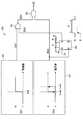
図1は、本発明の第1の実施形態に係る電源装置の構成の一例を示す回路図である。図1に示す電源装置1は、接続端子2(第1接続端子)、接続端子3(第2接続端子)、燃料電池4、DC−DCコンバータ5、二次電池6(蓄電素子)、電流検出部7(電流検出部)、制御部8、アンドゲート9,10、インバータ11、及びスイッチングコントローラ12を備えて構成されている。また、DC−DCコンバータ5、制御部8、スイッチングコントローラ12、アンドゲート9,10、及びインバータ11によって、同期整流型のスイッチング電源部の一例が構成されている。(First embodiment)
FIG. 1 is a circuit diagram showing an example of the configuration of the power supply device according to the first embodiment of the present invention. 1 includes a connection terminal 2 (first connection terminal), a connection terminal 3 (second connection terminal), a fuel cell 4, a DC-
DC−DCコンバータ5は、いわゆる同期整流型のDC−DCコンバータであり、コイルL1、スイッチング素子SW1(第1スイッチング素子)、及びスイッチング素子SW2(第2スイッチング素子)を備えている。なお、スイッチング電源部は、DC−DCコンバータを備える例に限られず、例えば同期整流型のAC−DCコンバータを備えるものであってもよい。 The DC-
また、接続端子2,3の間に負荷13が接続されている。接続端子2,3は、負荷13を接続するものであればよく、例えばコネクタであってもよく、ランドやパッド等の配線パターンであってもよい。負荷13は、電源装置1から電力供給を受ける電気機器、例えば携帯型のパーソナルコンピュータや携帯電話端末装置等の本体部である。 A
燃料電池4は、図略の燃料供給装置から供給されたメタノールや水素等の燃料に基づき発電を行い、得られた電力を正極端子と負極端子との間に出力する。そして、燃料電池4の正極端子は、電流検出部7、コイルL1、及びスイッチング素子SW1を介して接続端子2に接続されている。また、燃料電池4の負極端子は、接続端子3に接続されている。 The fuel cell 4 generates power based on a fuel such as methanol or hydrogen supplied from a fuel supply device (not shown), and outputs the obtained electric power between the positive electrode terminal and the negative electrode terminal. The positive terminal of the fuel cell 4 is connected to the
そして、二次電池6の正極端子が接続端子2に接続され、二次電池6の負極端子が接続端子3に接続されている。すなわち、スイッチング素子SW1と二次電池6とは、燃料電池4から見て直列に接続されている。さらに、コイルL1とスイッチング素子SW1との接続点と燃料供給装置の負極端子との間に、すなわちスイッチング素子SW1と二次電池6との直列回路と並列に、スイッチング素子SW2が接続されている。 The positive terminal of the secondary battery 6 is connected to the
これにより、二次電池6の両端電圧が電源装置1の出力電圧Voutとして、接続端子2,3を介して負荷13へ供給されるようになっている。 Thus, the voltage across the secondary battery 6 is supplied to the
二次電池6は、例えばリチウムイオン二次電池やニッケル水素二次電池等の蓄電素子が用いられる。この場合、二次電池6がリチウムイオン二次電池であれば、例えば出力電圧Voutは4.2Vとなり、二次電池6がニッケル水素二次電池であれば、例えば出力電圧Voutは1.2Vとなる。なお、二次電池6は、リチウムイオン二次電池やニッケル水素二次電池の電池セルが、複数個、直列又は並列に接続されたものであってもよい。また、蓄電素子として、二次電池6の代わりにコンデンサを用いてもよい。 As the secondary battery 6, for example, a storage element such as a lithium ion secondary battery or a nickel hydride secondary battery is used. In this case, if the secondary battery 6 is a lithium ion secondary battery, for example, the output voltage Vout is 4.2 V, and if the secondary battery 6 is a nickel metal hydride secondary battery, for example, the output voltage Vout is 1.2 V. Become. In addition, the secondary battery 6 may be one in which a plurality of battery cells of lithium ion secondary batteries or nickel hydride secondary batteries are connected in series or in parallel. In addition, a capacitor may be used instead of the secondary battery 6 as the power storage element.
スイッチング素子SW1,SW2としては、オン抵抗の小さいスイッチング素子、例えばパワーMOSFET(例えばインターナショナルレクティファイアー社製IRF7809)等のスイッチング素子を用いることができる。 As the switching elements SW1 and SW2, a switching element having a low on-resistance, for example, a switching element such as a power MOSFET (for example, IRF7809 manufactured by International Rectifier) can be used.
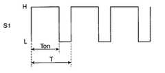
スイッチングコントローラ12は、スイッチング素子SW1,SW2のオンオフデューティを調節することにより、DC−DCコンバータ5の出力電圧Voutを制御するものである。そして、スイッチングコントローラ12は、燃料電池4の出力電圧、すなわちDC−DCコンバータ5の入力電圧をVin、二次電池6の両端電圧、すなわちDC−DCコンバータ5の出力電圧をVoutとすると、以下の式(2)の条件を満たすデューティ比Dを有する制御信号S1を出力する。 The switching
Vout/Vin=1/(1−D) ・・・(2)
式(2)において、Vout/Vinは、DC−DCコンバータ5の昇圧比αを示している。Vout / Vin = 1 / (1-D) (2)
In Expression (2), Vout / Vin represents the step-up ratio α of the DC-
なお、スイッチングコントローラ12は、デューティ比Dを調節することで、燃料電池4から出力される入力電圧Vinを、予め設定された設定出力電圧に保持するように、燃料電池4からDC−DCコンバータ5へ流入する出力電流Iinを調節することで、DC−DCコンバータ5を入力電圧一定型のDC−DCコンバータとして動作させるようにしてもよい。 Note that the switching
燃料電池4は、出力電圧によって発電効率が変化するので、スイッチングコントローラ12によって、DC−DCコンバータ5を、燃料電池4の出力電圧が良好な発電効率が得られる設定出力電圧になるように制御することで、燃料電池の発電効率を向上させることが可能になる。そして、スイッチングコントローラ12によってDC−DCコンバータ5が、入力電圧一定型のDC−DCコンバータとして制御されると、出力電流Iinがゼロになってもなお燃料電池4の出力電圧が設定出力電圧より低下した場合には、DC−DCコンバータ5は、二次電池6の出力電流を燃料電池4に逆流させることで燃料電池4の出力電圧を設定出力電圧に上昇させようとする。 Since the power generation efficiency of the fuel cell 4 varies depending on the output voltage, the DC-
そのため、入力電圧一定型のDC−DCコンバータでは、二次電池6の出力電流が燃料電池4に逆流して燃料電池4を劣化させるおそれが増大するが、このような場合であっても制御部8によって、制御信号S2がローレベルにされてスイッチング素子SW1,SW2が同時にオフされ、電流の逆流を抑制することができるので、燃料電池4を劣化させるおそれを低減することができる。従って、電源装置1は、入力電圧一定型のDC−DCコンバータと好適に組み合わせることができる。 For this reason, in a DC-DC converter of a constant input voltage type, there is an increased possibility that the output current of the secondary battery 6 will flow backward to the fuel cell 4 and deteriorate the fuel cell 4. Even in such a case, the
図2は、制御信号S1の一例を示す信号波形図である。図2に示すように、制御信号S1の周期をT、制御信号S1がハイレベル(H)の期間をTonとすると、デューティ比Dは、Ton/Tとなる。 FIG. 2 is a signal waveform diagram showing an example of the control signal S1. As shown in FIG. 2, assuming that the period of the control signal S1 is T and the period in which the control signal S1 is at a high level (H) is Ton, the duty ratio D is Ton / T.
そして、このようにして得られた制御信号S1が、スイッチングコントローラ12からアンドゲート9を介してスイッチング素子SW2へ出力され、制御信号S1がハイレベルでスイッチング素子SW2がオン、制御信号S1がローレベルでスイッチング素子SW2がオフすることにより、スイッチング素子SW2のオンデューティがデューティ比Dになるように、スイッチング素子SW2がオンオフされる。また、スイッチングコントローラ12から出力された制御信号S1は、インバータ11により反転された後、アンドゲート10を介してスイッチング素子SW1へ出力される。そうすると、スイッチング素子SW1は、スイッチング素子SW2がオンのときオフ、スイッチング素子SW2がオフのときオンすることとなり、すなわちスイッチング素子SW1及びスイッチング素子SW2が交互にオンオフされる。 The control signal S1 obtained in this way is output from the switching
このように、スイッチングコントローラ12からの制御信号S1に応じてスイッチング素子SW1,SW2のオン、オフ動作が制御されることにより、式(2)に応じて得られた出力電圧Voutが、DC−DCコンバータ5から接続端子2,3を介して負荷13へ出力される。そして、DC−DCコンバータ5の出力電力が負荷13の消費電力を上回ったときは、余剰電力が二次電池6に蓄えられ、DC−DCコンバータ5の出力電力が負荷13の消費電力を下回ったときは、電力の不足分が二次電池6から負荷13へ供給されることで、負荷13における消費電力の変動が吸収されるようになっている。 As described above, the on / off operation of the switching elements SW1 and SW2 is controlled in accordance with the control signal S1 from the switching
電流検出部7は、燃料電池4からDC−DCコンバータ5へ流れる出力電流Iinを検出し、その検出値を制御部8へ出力する。電流検出部7としては、例えばシャント抵抗やホール素子等の電流センサが用いられる。 The current detection unit 7 detects the output current Iin flowing from the fuel cell 4 to the DC-
制御部8は、例えばコンパレータを用いて構成されており、電流検出部7により検出された出力電流Iinが、予め設定された電流閾値Iref以下の場合、スイッチング素子SW1,SW2をオフさせる制御回路である。電流閾値Irefは、例えばゼロよりも僅かに大きい電流値が設定されている。図3は、制御部8の動作を説明するための信号波形図である。図3において、横軸は、電流検出部7により検出された出力電流Iinの電流値を示している。そして、制御部8から出力される制御信号S2は、出力電流Iinが電流閾値Iref以下の場合ローレベル(L)にされ、出力電流Iinが電流閾値Irefを超える場合ハイレベル(H)にされて、アンドゲート9,10へ出力される。 The
この場合、燃料電池4の出力電流Iinが電流閾値Iref以下に低下すると、制御部8によって制御信号S2がローレベルにされ、アンドゲート9,10の出力信号が共にローレベルにされて、スイッチング素子SW1,SW2が共にオフされる。 In this case, when the output current Iin of the fuel cell 4 falls below the current threshold value Iref, the control signal S2 is set to the low level by the
上述のように構成された電源装置1では、燃料電池4で生成された電力が、DC−DCコンバータ5へ供給される。そして、スイッチングコントローラ12から出力された制御信号S1に応じて、スイッチング素子SW2がデューティ比Dでオン、オフされる。また、スイッチング素子SW1は、インバータ11で反転された制御信号S1に応じてスイッチング素子SW2がオンのときにオフ、スイッチング素子SW2がオフのときにオンされる。 In the
このように、スイッチング素子SW1とスイッチング素子SW2とがスイッチングコントローラ12によって交互にオン、オフされることにより、燃料電池4で発電された電力が、DC−DCコンバータ5によって出力電圧Voutにされて、接続端子2,3を介して負荷13へ供給される。また、DC−DCコンバータ5の出力電力が負荷13の消費電力を上回ったときは、余剰電力が二次電池6に蓄えられ、DC−DCコンバータ5の出力電力が負荷13の消費電力を下回ったときは、電力の不足分が二次電池6から負荷13へ供給されることで、負荷13における消費電力の変動が吸収される。 As described above, the switching element SW1 and the switching element SW2 are alternately turned on and off by the switching
そして、例えば燃料電池4の燃料が不足する等の理由により燃料電池4の出力電流Iinが減少すると、電流検出部7により検出された出力電流Iinに基づき、制御部8によって、出力電流Iinの減少が進んで二次電池6から燃料電池4への電流の逆流が始まる前に、出力電流Iinが電流閾値Irefに達した際に、制御信号S2がローレベルにされ、アンドゲート9,10によってスイッチング素子SW1,SW2がオフされて電流の逆流が阻止されるので、同期整流型のDC−DCコンバータ5を用いて電力損失を低減させつつ燃料電池4が電流の逆流によって劣化するおそれを低減することができる。 When the output current Iin of the fuel cell 4 decreases due to, for example, a shortage of fuel in the fuel cell 4, the
(第2実施形態)
次に、本発明の第2の実施形態に係る電源装置について説明する。図4は、本発明の第2の実施形態に係る電源装置1aの構成の一例を示す回路図である。図4に示す電源装置1aは、図1に示す電源装置1とは、電圧検出部14をさらに備える点、及び制御部8aの構成が異なる点で異なる。その他の構成は図1に示す電源装置1と同様であるのでその説明を省略し、以下本実施形態の特徴的な点について説明する。(Second Embodiment)
Next, a power supply device according to a second embodiment of the present invention will be described. FIG. 4 is a circuit diagram showing an example of the configuration of the power supply device 1a according to the second embodiment of the present invention. The power supply device 1a shown in FIG. 4 is different from the
電圧検出部14は、燃料電池4の出力電圧、すなわちDC−DCコンバータ5の入力電圧Vinを検出し、入力電圧Vinの電圧値を制御部8aへ出力する。電圧検出部14は、例えば入力電圧Vinを制御部8aで取り扱い可能な電圧レベルに変換するための増幅器であってもよく、入力電圧Vinをそのまま制御部8aに印加する配線であってもよい。 The
制御部8aは、電流検出部7により検出された出力電流Iinの電流値が電流閾値Iref以下の場合と、電圧検出部14により検出された入力電圧Vinの電圧値が電圧閾値Vref1よりも低い電圧値に設定された電圧閾値Vref2以下の場合とに、制御信号S2をローレベルにして、アンドゲート9,10の出力信号をローレベルにすることでスイッチング素子SW1,SW2をオフさせる。 The
図5は、制御部8aの構成の一例を説明するための概念図である。図5に示す制御部8aは、例えば、電流比較部81、電圧比較部82、オアゲート83、アンドゲート84、及びマルチバイブレータ85(禁止制御部)を備えている。 FIG. 5 is a conceptual diagram for explaining an example of the configuration of the
電流比較部81は、電流検出部7により検出された出力電流Iinを電流閾値Irefと比較し、その比較結果を示す信号S21をオアゲート83へ出力する。電流比較部81は、例えば電流閾値Irefを示す基準電圧を生成する基準電圧源と、電流検出部7から出力された出力電流Iinを示す電圧と電流閾値Irefを示す基準電圧とを比較するコンパレータとを用いて構成されている。そして、電流比較部81によって、出力電流Iinの電流値が電流閾値Irefを超えた場合に信号S21はハイレベル(H)にされ、出力電流Iinの電流値が電流閾値Iref以下の場合に信号S21はローレベル(L)にされる。 The
電圧比較部82は、電圧検出部14により検出された入力電圧Vinを電圧閾値Vref1と比較し、入力電圧Vinが電圧閾値Vref1を超えた場合に、信号S22をハイレベル(H)にしてアンドゲート84とマルチバイブレータ85のトリガ端子Bとに出力する。また、電圧比較部82は、電圧検出部14により検出された入力電圧Vinを電圧閾値Vref2と比較し、入力電圧Vinが電圧閾値Vref2以下となった場合に、信号S22をローレベル(L)にしてアンドゲート84とマルチバイブレータ85のトリガ端子Bとに出力する。電圧比較部82は、例えばヒステリシスを有するコンパレータと、例えば電圧閾値Vref1,Vref2を示す基準電圧を生成する基準電圧源とを用いて構成されている。 The
マルチバイブレータ85は、禁止制御部の一例であって、電源装置1aの起動時に、出力電流Iinが流れていないために電流比較部81によって出力電流Iinの電流値が電流閾値Iref以下であると判定され、制御信号S2がローレベルにされてスイッチング素子SW1,SW2がオフされる結果、電源装置1aを起動することができなくなってしまうことを避けるため、電源装置1aの起動時において、出力電流Iinに基づくスイッチング素子SW1,SW2の制御動作を禁止させる。 The
マルチバイブレータ85は、信号S22が立ち上がると、出力パルス設定用の抵抗R及びキャパシタCによって設定された時間Tの間、Q出力信号S23をハイレベルにしてオアゲート83へ出力する。抵抗R及びキャパシタCの定数は、時間Tが、例えば1秒になるように、予め設定されている。 When the signal S22 rises, the
なお、禁止制御部は、DC−DCコンバータ5の動作を開始させる際に、電流比較部81によって出力電流Iinの電流値が電流閾値Iref以下であると判定されて制御信号S2がローレベルにされることを、燃料電池の出力電流がIref以上になる時間以上に予め設定された時間Tの間禁止するものであればよく、マルチバイブレータ85に限らない。例えば、ソフトウエアで起動から時間Tの間、強制的に電源部を動作させるようにしてもよい。 When the prohibition control unit starts the operation of the DC-
オアゲート83は、信号S21と信号S23とを論理和して得られた信号S24を、アンドゲート84へ出力する。アンドゲート84は、信号S22と信号S24とを論理積することにより、制御信号S2を生成してアンドゲート9,10へ出力する。 The
次に、上述のように構成された電源装置1aの動作について説明する。まず、電源装置1aが停止状態にされている場合、マルチバイブレータ85のQ出力信号S23はローレベルになっている。また、燃料電池4も動作しておらず、入力電圧Vinは0Vになっている。そうすると、電圧比較部82の出力信号S22はローレベルにされ、アンドゲート84によって制御信号S2がローレベルにされて、アンドゲート9,10の出力信号がローレベルにされ、スイッチング素子SW1,SW2がオフされている。 Next, the operation of the power supply device 1a configured as described above will be described. First, when the power supply device 1a is stopped, the Q output signal S23 of the
次に、電源装置1aの起動時に、例えば燃料電池4に燃料が供給されて燃料電池4の出力電圧Voutが上昇する。ここで、出力電圧Voutが上昇しても、スイッチング素子SW1,SW2がオフされているから出力電流Iinは増大せず、従って電流比較部81の出力信号S21はローレベルのままである。 Next, when the power supply device 1a is activated, for example, fuel is supplied to the fuel cell 4, and the output voltage Vout of the fuel cell 4 increases. Here, even if the output voltage Vout increases, the output current Iin does not increase because the switching elements SW1 and SW2 are turned off. Therefore, the output signal S21 of the
そして、燃料電池4の出力電圧Voutが、二次電池6からの電流の逆流が生じない電圧である電圧閾値Vref1を超えると、電圧比較部82によって、信号S22がハイレベルにされる。そうすると、信号S22の立上りでマルチバイブレータ85のQ出力信号S23が時間Tの間ハイレベルになり、オアゲート83の出力信号S24がハイレベルとなる。そうすると、信号S22と信号S24とは共にハイレベルになるので、アンドゲート84から制御信号S2がアンドゲート9,10へハイレベルで出力される。そして、アンドゲート9によって、スイッチングコントローラ12から出力された制御信号S1がスイッチング素子SW2へ出力されて、スイッチング素子SW2がデューティ比Dでオン、オフされる。また、アンドゲート10によって、インバータ11により反転された制御信号S1がスイッチング素子SW1へ出力され、スイッチング素子SW1は、スイッチング素子SW2がオンのときオフ、スイッチング素子SW2がオフのときオンされて、スイッチング素子SW1及びスイッチング素子SW2が交互にオンオフされる。 When the output voltage Vout of the fuel cell 4 exceeds the voltage threshold value Vref1, which is a voltage that does not cause a backflow of current from the secondary battery 6, the
これにより、燃料電池4で発電された電力が、DC−DCコンバータ5によって出力電圧Voutにされて、接続端子2,3を介して負荷13へ供給される。また、DC−DCコンバータ5の出力電力が負荷13の消費電力を上回ったときは、余剰電力が二次電池6に蓄えられ、DC−DCコンバータ5の出力電力が負荷13の消費電力を下回ったときは、電力の不足分が二次電池6から負荷13へ供給されることで、負荷13における消費電力の変動が吸収される。 Thereby, the electric power generated by the fuel cell 4 is converted to the output voltage Vout by the DC-
この場合、燃料電池4が、例えば燃料不足である等の理由により、燃料電池4の出力電流が減少し、ついには電流の向きが逆転しそうなときには、電流比較部81の出力がローレベルになり、二次電池6の出力電流がスイッチング素子SW1、コイルL1、及び電流検出部7を逆流して燃料電池4へ流入することが抑制される結果、燃料電池4の劣化が低減される。 In this case, when the fuel cell 4 has a shortage of fuel, for example, the output current of the fuel cell 4 decreases and finally the direction of the current is likely to reverse, the output of the
この場合、電圧閾値Vref2は、電圧閾値Vref1より低い電圧に設定されており、電圧閾値Vref1との間に差が設けられているので、入力電圧Vinが電圧閾値Vref2より高い電圧閾値Vref1を超えることによりDC−DCコンバータ5の動作が開始され、電圧閾値Vref1より低い電圧閾値Vref2以下の電圧まで低下したときにDC−DCコンバータ5の動作が停止される結果、例えば燃料電池4が発電を開始した直後である場合等、燃料電池4の出力電圧である入力電圧Vinが不安定な状態であっても、DC−DCコンバータ5の動作開始と停止とが繰り返されて動作が不安定になることが抑制される。 In this case, the voltage threshold Vref2 is set to a voltage lower than the voltage threshold Vref1, and a difference is provided between the voltage threshold Vref1 and the input voltage Vin exceeds the voltage threshold Vref1 higher than the voltage threshold Vref2. As a result, the operation of the DC-
なお、電圧閾値Vref1と電圧閾値Vref2との間には、必ずしも差が設けられている必要はなく、電圧閾値Vref1と電圧閾値Vref2とは、同一の電圧にされていてもよい。 Note that a difference is not necessarily provided between the voltage threshold value Vref1 and the voltage threshold value Vref2, and the voltage threshold value Vref1 and the voltage threshold value Vref2 may be the same voltage.
また、制御部8aは、コンパレータや論理ゲートを用いて構成する例に限られず、例えば、電流検出部7や電圧検出部14をADコンバータを用いて構成し、制御部8aをマイクロコンピュータを用いて構成するようにしてもよい。また、図4において、制御部8aは、電流比較部81と電圧比較部82とを備える例を示したが、例えば電流比較部81、マルチバイブレータ85、オアゲート83、及びアンドゲート84を備えず、電圧比較部82の出力信号S22を、そのまま制御信号S2としてアンドゲート9,10へ出力するようにしてもよい。 The
本発明に係る電源装置は、携帯電話、携帯情報端末(PDA)、携帯型パーソナルコンピュータ、ビデオカメラ等の携帯用小型電子機器へ燃料電池の電力を供給する際に有用である。また、電動車椅子、電動スクータ、ポータブル電源用等の燃料電池搭載に際しても適用できる。 The power supply device according to the present invention is useful when supplying fuel cell power to portable small electronic devices such as mobile phones, personal digital assistants (PDAs), portable personal computers, and video cameras. The present invention can also be applied when a fuel cell such as an electric wheelchair, an electric scooter, or a portable power source is mounted.
1,1a 電源装置
2,3 接続端子
4 燃料電池
5 DC−DCコンバータ
6 二次電池
7 電流検出部
8,8a 制御部
12 スイッチングコントローラ
13 負荷
14 電圧検出部
Iref 電流閾値
SW1,SW2 スイッチング素子
Vref1 電圧閾値
Vref2 電圧閾値DESCRIPTION OF
Claims (4)
Translated fromJapanese燃料電池と、
前記第1及び第2接続端子間に接続された蓄電素子と、
前記燃料電池の出力電圧を、前記蓄電素子の両端電圧と一致させるように変換して前記第1及び第2接続端子間に出力する同期整流型のスイッチング電源部と、
前記燃料電池の出力電流を検出する電流検出部とを備え、
前記スイッチング電源部は、
前記蓄電素子と直列に接続された第1スイッチング素子と、
前記蓄電素子と並列に接続された第2スイッチング素子と、
前記電流検出部により検出された出力電流が、予め設定された閾値以下の場合、前記第1及び第2スイッチング素子を同時にオフさせる同時オフ制御を行う制御部とを備えること
を特徴とする電源装置。First and second connection terminals for connecting a load;
A fuel cell;
A power storage element connected between the first and second connection terminals;
A synchronous rectification type switching power supply that converts the output voltage of the fuel cellto match the voltageacross the storage element and outputs the same between the first and second connection terminals;
A current detector for detecting an output current of the fuel cell;
The switching power supply unit
A first switching element connected in series with the power storage element;
A second switching element connected in parallel with the power storage element;
And a control unit that performs simultaneous off control for simultaneously turning off the first and second switching elements when an output current detected by the current detection unit is equal to or less than a preset threshold value. .
前記制御部は、さらに、前記電圧検出部により検出された電圧が、予め設定された電圧閾値を超える場合、前記第1及び第2スイッチング素子を交互にオン、オフさせることにより、前記スイッチング電源部に、電圧変換動作を開始させること
を特徴とする請求項1記載の電源装置。A voltage detection unit for detecting an output voltage of the fuel cell;
The control unit further turns on and off the first and second switching elements alternately when the voltage detected by the voltage detection unit exceeds a preset voltage threshold, thereby switching the switching power supply unit. The power supply device according to claim 1, wherein a voltage conversion operation is started.
を特徴とする請求項1又は2記載の電源装置。The control unit includes a prohibition control unit that prohibits the simultaneous off control based on the output current detected by the current detection unit for a preset time when the switching power supply unit starts a voltage conversion operation. The power supply device according to claim 1, wherein:
を特徴とする請求項1〜3のいずれか1項に記載の電源装置。The switching power supply unit controls a duty ratio for alternately turning on and off the first and second switching elements so as to maintain an output voltage of the fuel cell at a predetermined set output voltage, and from the fuel cell The power supply device according to any one of claims 1 to 3, wherein an amount of current flowing into the switching power supply unit is adjusted.
Priority Applications (2)
| Application Number | Priority Date | Filing Date | Title |
|---|---|---|---|
| JP2006217465AJP4898343B2 (en) | 2006-08-09 | 2006-08-09 | Power supply |
| US11/882,972US7994765B2 (en) | 2006-08-09 | 2007-08-08 | Power supply device |
Applications Claiming Priority (1)
| Application Number | Priority Date | Filing Date | Title |
|---|---|---|---|
| JP2006217465AJP4898343B2 (en) | 2006-08-09 | 2006-08-09 | Power supply |
Publications (2)
| Publication Number | Publication Date |
|---|---|
| JP2008043146A JP2008043146A (en) | 2008-02-21 |
| JP4898343B2true JP4898343B2 (en) | 2012-03-14 |
Family
ID=39050089
Family Applications (1)
| Application Number | Title | Priority Date | Filing Date |
|---|---|---|---|
| JP2006217465AExpired - Fee RelatedJP4898343B2 (en) | 2006-08-09 | 2006-08-09 | Power supply |
Country Status (2)
| Country | Link |
|---|---|
| US (1) | US7994765B2 (en) |
| JP (1) | JP4898343B2 (en) |
Families Citing this family (23)
| Publication number | Priority date | Publication date | Assignee | Title |
|---|---|---|---|---|
| EP2216877B1 (en)* | 2009-02-05 | 2013-11-27 | ams AG | DC/DC converter and method for controlling a DC/DC converter |
| TWI376860B (en)* | 2009-04-08 | 2012-11-11 | Young Green Energy Co | Fuel cell system and power management method thereof |
| CN102449893B (en)* | 2009-06-03 | 2014-08-06 | 丰田自动车株式会社 | Converter control device |
| JP5327486B2 (en)* | 2009-06-22 | 2013-10-30 | トヨタ自動車株式会社 | Converter control device |
| US8358033B2 (en)* | 2009-07-20 | 2013-01-22 | General Electric Company | Systems, methods, and apparatus for converting DC power to AC power |
| DE102009041217B4 (en) | 2009-09-11 | 2021-11-11 | Austriamicrosystems Ag | Voltage converter and method for voltage conversion |
| JP5549280B2 (en)* | 2010-03-05 | 2014-07-16 | トヨタ自動車株式会社 | Chopper circuit, DC / DC converter, fuel cell system |
| GB2511994B (en)* | 2012-01-23 | 2018-07-11 | Murata Manufacturing Co | Switching power supply apparatus |
| JP5910172B2 (en)* | 2012-03-01 | 2016-04-27 | 株式会社Gsユアサ | Switch failure diagnosis device, battery pack, switch failure diagnosis program, switch failure diagnosis method |
| JP5880239B2 (en)* | 2012-04-13 | 2016-03-08 | 株式会社ソシオネクスト | Power supply device and power supply control method |
| CN102881956B (en)* | 2012-09-28 | 2014-07-23 | 引峰新能源科技(上海)有限公司 | Hybrid power source energy management method of fuel battery |
| JP2014217211A (en)* | 2013-04-26 | 2014-11-17 | 株式会社東芝 | Charging device, charging method and electronic device |
| EP3006166A4 (en)* | 2013-05-31 | 2017-04-19 | Hitachi Koki Co., Ltd. | Power tool |
| WO2016019744A1 (en)* | 2014-08-08 | 2016-02-11 | 清华大学 | Integrated dc/dc converter and electrochemical energy storage system as well as alternating-current impedance analytical method for electrochemical energy storage device and analytical method for working state of electrochemical energy storage device |
| WO2017195370A1 (en)* | 2016-05-13 | 2017-11-16 | 三菱電機株式会社 | Electrical power converter |
| DE102017214445B4 (en)* | 2017-08-18 | 2025-03-20 | Audi Ag | Method for operating a fuel cell arrangement and corresponding fuel cell arrangement |
| DE102017214440A1 (en) | 2017-08-18 | 2019-02-21 | Audi Ag | Method for operating a fuel cell assembly and corresponding fuel cell assembly |
| JP6495413B1 (en)* | 2017-10-19 | 2019-04-03 | 本田技研工業株式会社 | Power system |
| CN112655145B (en)* | 2018-11-19 | 2023-12-05 | 深圳迈瑞生物医疗电子股份有限公司 | Power supply device and ultrasonic trolley |
| WO2021241622A1 (en)* | 2020-05-29 | 2021-12-02 | 国立研究開発法人科学技術振興機構 | Power conversion circuit, semiconductor device, and electronic apparatus |
| US12388361B2 (en)* | 2020-06-02 | 2025-08-12 | Qualcomm Incorporated | Battery charging circuit and methods for trickle charging and precharging a dead multi-cell-in-series battery |
| CN113544931A (en)* | 2020-09-28 | 2021-10-22 | 深圳市大疆创新科技有限公司 | Power supply device, control method of power supply device, and storage medium |
| CN116487655A (en)* | 2023-04-26 | 2023-07-25 | 深圳市氢瑞燃料电池科技有限公司 | A fuel cell system without DC/DC converter |
Family Cites Families (14)
| Publication number | Priority date | Publication date | Assignee | Title |
|---|---|---|---|---|
| JP3661826B2 (en)* | 1997-11-06 | 2005-06-22 | 富士電機ホールディングス株式会社 | Fuel cell power generation control method |
| JP3580236B2 (en)* | 2000-10-04 | 2004-10-20 | 日産自動車株式会社 | Fuel cell system |
| JP3776752B2 (en)* | 2001-06-07 | 2006-05-17 | 新電元工業株式会社 | DC-DC converter |
| US6707281B2 (en)* | 2002-06-28 | 2004-03-16 | Intel Corporation | Method and apparatus for operating a voltage regulator based on inductor current detection |
| US6590370B1 (en)* | 2002-10-01 | 2003-07-08 | Mti Microfuel Cells Inc. | Switching DC-DC power converter and battery charger for use with direct oxidation fuel cell power source |
| US7932634B2 (en)* | 2003-03-05 | 2011-04-26 | The Gillette Company | Fuel cell hybrid power supply |
| US20040217732A1 (en)* | 2003-04-29 | 2004-11-04 | Ballard Power Systems Inc. | Power converter architecture and method for integrated fuel cell based power supplies |
| WO2005013455A1 (en)* | 2003-08-05 | 2005-02-10 | Matsushita Electric Industrial Co., Ltd. | Direct-current power supply and battery-powered electronic apparatus equipped with the power supply |
| JP4583010B2 (en)* | 2003-08-19 | 2010-11-17 | パナソニック株式会社 | Power supply control method |
| JP4791689B2 (en)* | 2003-10-06 | 2011-10-12 | パナソニック株式会社 | Power supply |
| JP2006054976A (en)* | 2004-08-16 | 2006-02-23 | Hitachi Ltd | Fuel cell equipment |
| JP3979417B2 (en)* | 2004-11-29 | 2007-09-19 | セイコーエプソン株式会社 | Power supply control circuit, electronic device, semiconductor device, control method for power supply control circuit, and control method for electronic device |
| US20060194082A1 (en)* | 2005-02-02 | 2006-08-31 | Ultracell Corporation | Systems and methods for protecting a fuel cell |
| TWI274454B (en)* | 2005-03-04 | 2007-02-21 | Ind Tech Res Inst | A power management method and system of a hybrid power supply |
- 2006
- 2006-08-09JPJP2006217465Apatent/JP4898343B2/ennot_activeExpired - Fee Related
- 2007
- 2007-08-08USUS11/882,972patent/US7994765B2/ennot_activeExpired - Fee Related
Also Published As
| Publication number | Publication date |
|---|---|
| JP2008043146A (en) | 2008-02-21 |
| US7994765B2 (en) | 2011-08-09 |
| US20080036432A1 (en) | 2008-02-14 |
Similar Documents
| Publication | Publication Date | Title |
|---|---|---|
| JP4898343B2 (en) | Power supply | |
| JP5261942B2 (en) | POWER SUPPLY CIRCUIT FOR POWER SUPPLYING CHARGE CONTROL CIRCUIT, CHARGING DEVICE HAVING THE POWER SOURCE CIRCUIT, AND METHOD FOR POWER SUPPLYING CHARGE CONTROL CIRCUIT | |
| CN1893216B (en) | Electronic equipment and battery components and load devices used in the electronic equipment | |
| JP5167645B2 (en) | Electronic equipment and DC voltage conversion system | |
| US20060222916A1 (en) | Mehotd for determining a maximum power point voltage of a fuel cell, as well as fuel cell control system and power controller used in the fuel cell control system | |
| CN1922779B (en) | Switching regulator and method for switching its output voltage | |
| US7750597B2 (en) | Power supply apparatus | |
| US20070077468A1 (en) | Power supply apparatus with fuel cell and method of controlling the same | |
| CN102498635B (en) | Hybrid power supply system | |
| US20050112420A1 (en) | Power supply device | |
| JP2009232665A (en) | Power supply device and power supply control method | |
| US7652454B2 (en) | Electronic equipment having a boost DC-DC converter | |
| US20070237989A1 (en) | Power source system using a fuel cell and its control method | |
| JP4564940B2 (en) | Electronic device and battery pack and load device used in the electronic device | |
| JP5131805B2 (en) | Fuel cell system | |
| JP2008243728A (en) | Power circuit equipment | |
| JP4435179B2 (en) | Power supply | |
| JP4073880B2 (en) | Electronics | |
| JP2011211812A (en) | Power unit | |
| JP2007299532A (en) | Fuel cell system | |
| KR100797187B1 (en) | SuperPCM equipped with ACLC and ECC to increase battery discharge capacity | |
| JP2008021464A (en) | Fuel cell system | |
| JP4976663B2 (en) | Electronics | |
| JP2006067759A (en) | Power supply apparatus using solar battery | |
| JP2008148370A (en) | Power supply system, power supply system control method, and power supply system control program |
Legal Events
| Date | Code | Title | Description |
|---|---|---|---|
| A621 | Written request for application examination | Free format text:JAPANESE INTERMEDIATE CODE: A621 Effective date:20090703 | |
| A977 | Report on retrieval | Free format text:JAPANESE INTERMEDIATE CODE: A971007 Effective date:20110914 | |
| A131 | Notification of reasons for refusal | Free format text:JAPANESE INTERMEDIATE CODE: A131 Effective date:20110927 | |
| A521 | Written amendment | Free format text:JAPANESE INTERMEDIATE CODE: A523 Effective date:20111007 | |
| TRDD | Decision of grant or rejection written | ||
| A01 | Written decision to grant a patent or to grant a registration (utility model) | Free format text:JAPANESE INTERMEDIATE CODE: A01 Effective date:20111206 | |
| A01 | Written decision to grant a patent or to grant a registration (utility model) | Free format text:JAPANESE INTERMEDIATE CODE: A01 | |
| A61 | First payment of annual fees (during grant procedure) | Free format text:JAPANESE INTERMEDIATE CODE: A61 Effective date:20111226 | |
| R150 | Certificate of patent or registration of utility model | Ref document number:4898343 Country of ref document:JP Free format text:JAPANESE INTERMEDIATE CODE: R150 Free format text:JAPANESE INTERMEDIATE CODE: R150 | |
| FPAY | Renewal fee payment (event date is renewal date of database) | Free format text:PAYMENT UNTIL: 20150106 Year of fee payment:3 | |
| LAPS | Cancellation because of no payment of annual fees |