JP4897387B2 - Storage apparatus and data management method using the same - Google Patents
Storage apparatus and data management method using the sameDownload PDFInfo
- Publication number
- JP4897387B2 JP4897387B2JP2006218292AJP2006218292AJP4897387B2JP 4897387 B2JP4897387 B2JP 4897387B2JP 2006218292 AJP2006218292 AJP 2006218292AJP 2006218292 AJP2006218292 AJP 2006218292AJP 4897387 B2JP4897387 B2JP 4897387B2
- Authority
- JP
- Japan
- Prior art keywords
- repeater
- disk device
- power saving
- storage
- storage device
- Prior art date
- Legal status (The legal status is an assumption and is not a legal conclusion. Google has not performed a legal analysis and makes no representation as to the accuracy of the status listed.)
- Expired - Fee Related
Links
Images


Classifications
- G—PHYSICS
- G06—COMPUTING OR CALCULATING; COUNTING
- G06F—ELECTRIC DIGITAL DATA PROCESSING
- G06F3/00—Input arrangements for transferring data to be processed into a form capable of being handled by the computer; Output arrangements for transferring data from processing unit to output unit, e.g. interface arrangements
- G06F3/06—Digital input from, or digital output to, record carriers, e.g. RAID, emulated record carriers or networked record carriers
- G06F3/0601—Interfaces specially adapted for storage systems
- G06F3/0628—Interfaces specially adapted for storage systems making use of a particular technique
- G06F3/0629—Configuration or reconfiguration of storage systems
- G06F3/0634—Configuration or reconfiguration of storage systems by changing the state or mode of one or more devices
- G—PHYSICS
- G06—COMPUTING OR CALCULATING; COUNTING
- G06F—ELECTRIC DIGITAL DATA PROCESSING
- G06F1/00—Details not covered by groups G06F3/00 - G06F13/00 and G06F21/00
- G06F1/26—Power supply means, e.g. regulation thereof
- G06F1/32—Means for saving power
- G06F1/3203—Power management, i.e. event-based initiation of a power-saving mode
- G06F1/3206—Monitoring of events, devices or parameters that trigger a change in power modality
- G06F1/3215—Monitoring of peripheral devices
- G06F1/3221—Monitoring of peripheral devices of disk drive devices
- G—PHYSICS
- G06—COMPUTING OR CALCULATING; COUNTING
- G06F—ELECTRIC DIGITAL DATA PROCESSING
- G06F1/00—Details not covered by groups G06F3/00 - G06F13/00 and G06F21/00
- G06F1/26—Power supply means, e.g. regulation thereof
- G06F1/32—Means for saving power
- G06F1/3203—Power management, i.e. event-based initiation of a power-saving mode
- G06F1/3234—Power saving characterised by the action undertaken
- G06F1/325—Power saving in peripheral device
- G06F1/3268—Power saving in hard disk drive
- G—PHYSICS
- G06—COMPUTING OR CALCULATING; COUNTING
- G06F—ELECTRIC DIGITAL DATA PROCESSING
- G06F3/00—Input arrangements for transferring data to be processed into a form capable of being handled by the computer; Output arrangements for transferring data from processing unit to output unit, e.g. interface arrangements
- G06F3/06—Digital input from, or digital output to, record carriers, e.g. RAID, emulated record carriers or networked record carriers
- G06F3/0601—Interfaces specially adapted for storage systems
- G06F3/0602—Interfaces specially adapted for storage systems specifically adapted to achieve a particular effect
- G06F3/0625—Power saving in storage systems
- G—PHYSICS
- G06—COMPUTING OR CALCULATING; COUNTING
- G06F—ELECTRIC DIGITAL DATA PROCESSING
- G06F3/00—Input arrangements for transferring data to be processed into a form capable of being handled by the computer; Output arrangements for transferring data from processing unit to output unit, e.g. interface arrangements
- G06F3/06—Digital input from, or digital output to, record carriers, e.g. RAID, emulated record carriers or networked record carriers
- G06F3/0601—Interfaces specially adapted for storage systems
- G06F3/0668—Interfaces specially adapted for storage systems adopting a particular infrastructure
- G06F3/0671—In-line storage system
- G06F3/0683—Plurality of storage devices
- G06F3/0689—Disk arrays, e.g. RAID, JBOD
- Y—GENERAL TAGGING OF NEW TECHNOLOGICAL DEVELOPMENTS; GENERAL TAGGING OF CROSS-SECTIONAL TECHNOLOGIES SPANNING OVER SEVERAL SECTIONS OF THE IPC; TECHNICAL SUBJECTS COVERED BY FORMER USPC CROSS-REFERENCE ART COLLECTIONS [XRACs] AND DIGESTS
- Y02—TECHNOLOGIES OR APPLICATIONS FOR MITIGATION OR ADAPTATION AGAINST CLIMATE CHANGE
- Y02D—CLIMATE CHANGE MITIGATION TECHNOLOGIES IN INFORMATION AND COMMUNICATION TECHNOLOGIES [ICT], I.E. INFORMATION AND COMMUNICATION TECHNOLOGIES AIMING AT THE REDUCTION OF THEIR OWN ENERGY USE
- Y02D10/00—Energy efficient computing, e.g. low power processors, power management or thermal management
Landscapes
- Engineering & Computer Science (AREA)
- Theoretical Computer Science (AREA)
- Physics & Mathematics (AREA)
- General Engineering & Computer Science (AREA)
- General Physics & Mathematics (AREA)
- Human Computer Interaction (AREA)
- Power Sources (AREA)
- Signal Processing For Digital Recording And Reproducing (AREA)
Description
Translated fromJapanese本発明は、ストレージ装置およびこれを用いたデータの管理方法に関し、特に、ディスクデバイスの省電力制御の技術に関する。 The present invention relates to a storage apparatus and a data management method using the same, and more particularly to a technology for power saving control of a disk device.
コンピュータシステムが処理するデータの量は、ハードウェア技術の進歩と相まって、ますます増加している。ストレージ装置は、このような膨大な量のデータを管理する、コンピュータシステムにおける中核装置である。 The amount of data that a computer system processes is increasing, coupled with advances in hardware technology. The storage device is a core device in a computer system that manages such a huge amount of data.
ストレージ装置の導入、運用に際しては、一般に、データの維持管理コストを低く抑えたいという要望がある。データの維持管理コストには、典型的には、単位ビット当たりの単価(ビットコスト)や運用時の消費電力コストが含まれる。 In installing and operating a storage apparatus, there is a general demand for keeping data maintenance costs low. Typically, the data maintenance management cost includes a unit price per bit (bit cost) and a power consumption cost during operation.
ストレージ装置に対して要求される仕様を満たしつつ、ビットコストを低減するため、相異なる性能を有するディスクデバイスを組み合わせる技術が知られている。例えば、下記特許文献1に示されるように、大容量かつ安価なSATAディスクデバイスと高信頼性かつ高価なFCディスクデバイスとを階層的に組み合わせたストレージ装置がある。これによれば、優先度が高いデータはFCディスクデバイスに格納され、比較的優先度が低いデータはSATAディスクデバイスに格納される。 In order to reduce the bit cost while satisfying the specifications required for the storage apparatus, a technique for combining disk devices having different performances is known. For example, as shown in
一方、運用時の消費電力コストを低減するため、データのアクセスが長時間行われていないディスクデバイスを停止させる技術が知られている。例えば、下記特許文献2に示されるように、ホスト装置から与えられるI/Oコマンドの受信頻度に応じてディスクデバイスの稼働を制限し、当該頻度が少ないディスクデバイスを停止することによって、消費電力を抑えるストレージ装置がある。
ストレージ装置に対する大容量化の要求に伴って、ストレージ装置に搭載されるディスクデバイスの台数は増加する傾向にある。ディスクデバイスを制御するコントローラが必要とするシステムリソースは、ディスクデバイス台数の増加に比例するため、ディスクデバイスの停止及び起動といった省電力制御は、I/Oアクセス要求といったコントローラ本来の処理パフォーマンスに影響を与えるおそれがある。また、このような省電力制御は、コントローラのメモリリソースを多量に消費してしまう。したがって、処理パフォーマンスの維持を目的にメモリの大容量化を図ることは、ストレージ装置自体のコスト上昇を招くことになり、コスト低減の目的に反することになる。 The number of disk devices installed in a storage device tends to increase with the demand for a larger capacity for the storage device. Since the system resources required by the controller that controls the disk devices are proportional to the increase in the number of disk devices, power-saving controls such as stopping and starting disk devices affect the processing performance inherent to the controller such as I / O access requests. There is a risk of giving. Further, such power saving control consumes a large amount of memory resources of the controller. Therefore, increasing the capacity of the memory for the purpose of maintaining the processing performance leads to an increase in the cost of the storage apparatus itself, which is contrary to the purpose of reducing the cost.
本発明の一観点によれば、本発明は、コントローラと、階層的に配置されパフォーマンスの異なる複数のディスクデバイスとの間に中継器を配置したストレージ装置である。コントローラは、ホスト装置から送られるアクセス要求に基づいて、中継器を介して、ディスクデバイスに対してI/Oアクセスを行う。中継器は、ディスクデバイスに対する省電力制御機能を含み、予め設定された条件に従って、ディスクデバイスの停止や起動といった動作制御を行う。 According to one aspect of the present invention, the present invention is a storage apparatus in which a repeater is disposed between a controller and a plurality of disk devices that are hierarchically arranged and have different performances. The controller performs I / O access to the disk device via the relay device based on the access request sent from the host device. The repeater includes a power saving control function for the disk device, and performs operation control such as stop and start of the disk device according to preset conditions.
また、本発明の一観点によれば、本発明は、ホスト装置からのアクセス要求に応じた処理を行うコントローラユニットと、当該コントローラユニットに接続され、複数のポートを有する1以上の中継器と、当該中継器の複数のポートにそれぞれ接続された複数のディスクデバイスと、を備えたストレージ装置である。当該中継器は、当該アクセス要求に従って選択される当該複数のポートのいずれかを介して、当該アクセス要求に応じた処理を中継するとともに、前記コントローラに介在させることなく、当該複数のポートのいずれかに接続されたディスクデバイスに対する省電力制御を行う。 According to another aspect of the present invention, the present invention provides a controller unit that performs processing in response to an access request from a host device, one or more repeaters connected to the controller unit, and having a plurality of ports; And a plurality of disk devices respectively connected to a plurality of ports of the repeater. The repeater relays the processing according to the access request via any of the plurality of ports selected according to the access request, and does not intervene in the controller. Power saving control is performed on the disk device connected to the.
当該複数のディスクデバイスは、第1のディスクデバイス群と、当該第1のディスクデバイス群と異なる性能を有する第2のディスクデバイス群とから構成され、典型的には、SAS規格のハードディスクデバイス群と、SATA規格のハードディスクデバイス群から構成される。 The plurality of disk devices are composed of a first disk device group and a second disk device group having a performance different from that of the first disk device group. , SATA standard hard disk device group.
また、当該中継器は、所定のパワーマネージメントに関するプロファイルを備え、当該所定のパワーマネージメントに関するプロファイルに定義される省電力モード移行条件に従って、当該複数のディスクデバイスのいずれかを省電力モードに移行させる。 The repeater includes a profile related to predetermined power management, and shifts one of the plurality of disk devices to the power saving mode in accordance with the power saving mode shift condition defined in the profile related to the predetermined power management.
さらに、本発明の一観点によれば、本発明は、複数のディスクデバイスに対する省電力制御方法である。当該省電力制御方法は、コントローラユニットが、ホスト装置からのアクセス要求を受け取り、当該受け取ったアクセス要求に相当する内部的なアクセス要求を中継器に送出し、当該中継器が、当該アクセス要求に従って選択される当該中継器の複数のポートのいずれかを介して、当該アクセス要求を転送する一方、当該中継器は、所定のパワーマネージメントに関するプロファイルに従い、当該複数のポートのいずれかに接続されたディスクデバイスに対する省電力制御を行う。 Furthermore, according to one aspect of the present invention, the present invention is a power saving control method for a plurality of disk devices. In the power saving control method, the controller unit receives an access request from the host device, sends an internal access request corresponding to the received access request to the repeater, and the repeater selects according to the access request. The access device transfers the access request via one of the plurality of ports of the relay device, while the relay device is connected to one of the plurality of ports according to a predetermined power management profile. Power-saving control for
本発明によれば、データの維持管理コストを低く抑えつつ、高信頼性や高速性等のパフォーマンスを備えたストレージ装置が提供される。 According to the present invention, it is possible to provide a storage apparatus having performance such as high reliability and high speed while keeping data maintenance cost low.
次に、本発明の実施の形態について、図面を参照しつつ説明する。 Next, embodiments of the present invention will be described with reference to the drawings.
本発明に係るストレージ装置においては、図1に示すように、コントローラユニット42と、階層的に配置されパフォーマンスの異なる複数のディスクデバイス41との間に中継器(エクスパンダ)43を配置し、コントローラユニット42は、ホスト装置から送られるアクセス要求に基づいて、中継器43を介して、ディスクデバイス41に対してI/O処理を行う。中継器43は、ディスクデバイス41に対する省電力制御機能を含み、予め設定された条件に従って、ディスクデバイスの停止や起動といった動作制御を行う。
[第1の実施形態]
図2は、本発明の一実施形態に係るストレージシステムの構成を示している。同図に示すように、ストレージシステム1は、ネットワークシステム3を介してホスト装置2に接続されたストレージ装置4を含む。ストレージシステム1はまた、ストレージ装置4に接続された管理端末5を含む。In the storage apparatus according to the present invention, as shown in FIG. 1, a repeater (expander) 43 is arranged between a
[First Embodiment]
FIG. 2 shows a configuration of a storage system according to an embodiment of the present invention. As shown in the figure, the
ホスト装置2は、典型的には、パーソナルコンピュータやワークステーション、メインフレーム等が該当する。ホスト装置2は、CPU21、ローカルメモリ22、インターフェース23およびローカル入出力装置24等のハードウェア資源を備え、これらは内部バス25により相互に接続されている。ホスト装置2はまた、デバイスドライバやオペレーティングシステム(OS)、アプリケーションプログラム等のソフトウェア資源を備えている。 Typically, the
これによって、ホスト装置2は、CPU21の制御の下、各種のプログラムを実行して、ハードウェア資源との協働作用により、所望の処理を実現する。典型的には、ホスト装置2は、CPU21の制御の下、OS上でアプリケーションプログラムを実行する。アプリケーションプログラムは、ユーザがホスト装置2によって遂行しようとする処理を実現するためのプログラムである。アプリケーションプログラムは、その実行に際して、ストレージ装置4に対してデータの読み込みや書き込み等のアクセスを要求する。ホスト装置2に実装されたストレージマネージャは、アプリケーションプログラムからのアクセス要求をコマンドとしてストレージ装置4に引き渡し、また、ストレージ装置4から読み出したデータをアプリケーションプログラムに引き渡す。ストレージマネージャは、OSとは独立に設計されてもよいし、またはその一部として組み込まれていてもよい。各種のプログラムは、1つのモジュールとして構成されてもよいし、複数のモジュールとして構成されてもよい。 As a result, the
ネットワークシステム3は、例えばSAN(Storage Area Network)、LAN、インターネット、公衆回線又は専用回線などから構成される。ネットワークシステム3を介したホスト装置2とストレージ装置4との間の通信は、所定のプロトコルに従って行われる。例えば、ネットワーク3がファイバチャネル統合型のSANであれば、ファイバーチャネルプロトコルが用いられる。また、ネットワーク3がLANであれば、通常、TCP/IPプロトコルが用いられる。 The
ストレージ装置4は、複数のディスクデバイス41と、ディスクデバイス41に対する書き込みまたは読み込みといったアクセスを制御するコントローラユニット42と、当該ディスクデバイス41と当該コントローラユニット42との間でアクセス制御を中継するとともに、ディスクデバイス41に対する省電力制御を行う中継器43と、を備えている。中継器43は、いわゆる「エッジ型」または「ファンアウト型」といった目的種別に対応し、接続するディスクデバイス41の台数やシステム規模等に応じて、一又は複数から構成される。なお、中継器43は、SASプロトコルによる通信を行うSASエクスパンダとすることもできる。もしくは、中継器43をFCプロトコルによる通信を行うスイッチとすることもできる。 The
管理端末5は、システム管理者がストレージ装置4全体を管理するために使用するコンピュータ装置である。例えば、管理端末5には、ストレージ装置4の省電力制御を設定するためのユーティリティツールが実装され、システム管理者に対するユーザインターフェースを提供している。管理端末5は、ストレージ装置4と専用線やLANにより接続されてもよいし、ネットワークシステム3を介して接続されてもよい。本実施形態では、管理端末5がストレージ装置4に外的に接続されているが、ストレージ装置4が、自身を管理するためのサービスプロセッサ(SVP)及びユーザインターフェースを備えた構成であってもよい。 The
ディスクデバイス41は、異なる規格乃至は種類のハードディスクデバイス(HDD)群からなり、これによって、例えば保存すべきデータの性質に応じた、記憶領域の階層的な利用ができるようになっている。具体的には、高いパフォーマンスが要求される階層には、例えばSAS規格のハードディスクデバイス(SASディスクデバイス)が採用され、大容量かつ低いビットコストが要求される階層には、例えばシリアルATA規格のハードディスクデバイス(SATAディスクデバイス)が採用される。本実施形態においては、ディスクデバイス41は、SASディスクデバイス群41aとSATAディスクデバイス群41bとから構成されている。各ディスクデバイス41は図示しないポートを備え、中継器43に設けられたポートとそれぞれ接続される。これによって、ディスクデバイス41とは、所定のプロトコルに従って、中継器43を介してコントローラユニット42によるアクセス制御が行われる。 The
1又は複数のディスクデバイス41によって提供される記憶領域上には、1又は複数の論理的なボリュームLUが定義される。本実施形態では、SASディスクデバイス41a上に論理ボリュームSAS−LUおよびSATAディスクデバイス41b上に論理ボリュームSATA−LUが定義されている。 One or more logical volumes LU are defined on a storage area provided by one or
論理ボリュームLUには、固有の識別子(LUN:Logical Unit Number)が割り当てられ、論理ボリュームは当該識別子によって管理される。論理ボリュームLUに対するアクセスは、所定サイズのブロックを単位として行われる。各ブロックには、論理ブロックアドレス(LBA:Logical Block Address)が割り当てられている。したがって、ホスト装置2は、識別子および論理ブロックアドレスに基づく論理アドレスをストレージ装置4のコントローラユニット42に対して指定することにより、所望の論理ボリューム上のブロックに対してアクセスを行うことができる。 A unique identifier (LUN: Logical Unit Number) is assigned to the logical volume LU, and the logical volume is managed by the identifier. Access to the logical volume LU is performed in units of blocks of a predetermined size. Each block is assigned a logical block address (LBA). Therefore, the
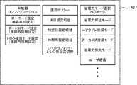
コントローラユニット42は、主として、CPU421と、メモリ422と、キャッシュ機構423とを備えたシステム回路であり、ホスト装置2とディスクデバイス41との間の入出力処理を統括的に制御する。また、コントローラユニット42は、1又は複数のチャネルアダプタ424及び1又は複数のディスクインターフェース425を備える。さらに、コントローラユニット42は、管理端末5との接続を可能にするための外部インターフェース426を備える。これらのシステム要素は、データコントローラ427に機能的に接続されている。 The
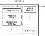
メモリ422は、CPU421のメインメモリとして機能する。メモリ422は、CPU421の利用に供されるべく、図3に示すように、例えば、各種の制御プログラム及びシステム構成情報や管理テーブル等のプロファイルを記憶する。本実施形態では、制御プログラムとして、I/O制御プログラムや中継器制御プログラムが実装されている。これら制御プログラムや各種のプロファイル等は、例えば、ストレージ装置4に電源が投入された時点で、CPU421の制御の下、特定のディスクデバイス41上の論理ボリュームLUから読み出され、メモリ422上に展開される。または、メモリ422が再書き込み可能な不揮発性メモリを含んで構成されている場合には、当該不揮発性メモリに恒常的に保持されていてもよい。 The
図2に戻り、キャッシュ機構423はキャッシュメモリを備え、ホスト装置2とディスクデバイス41との間の入出力データを一時的に記憶するために利用される。ホスト装置2から送られるコマンドは、キャッシュメモリに一旦保持され、また、ディスクデバイス41から読み出されたデータは、ホスト装置2に送り出す際に、キャッシュメモリに一旦保持される。 Returning to FIG. 2, the
チャネルアダプタ424は、それ自体、マイクロプロセッサと、メモリと、通信インターフェースとを備えたシステム回路であり、ネットワークシステム3に接続するためのポートを提供している。チャネルアダプタ424は、ホスト装置2からネットワークシステム3を介して送信される各種のコマンドを解釈し、実行する。チャネルアダプタ424のポートには、ネットワークアドレスが割り当てられている。これにより、個々のチャネルアダプタは、ネットワークシステム3上で識別され、SANストレージやNAS(Network Attached Storage)として機能することができるようになっている。 The
ディスクインターフェース425は、中継器43に対する入出力インターフェースを提供している。コントローラユニット42は、ディスクインターフェース425を介して中継器43と接続される。 The
中継器43は、複数のポート434を備え(図4参照)、ポイント・ツー・ポイント方式により、各ポートにディスクデバイス41を接続している。中継器43は、ある種のスイッチングデバイスとして機能し、コントローラユニット42とディスクデバイス41との間のデータ通信を調停し、スイッチングを行う。本実施形態における中継器43はさらに、省電力制御部を備え、各ディスクデバイス41に対する省電力制御を行っている。省電力制御は、例えば、ディスクデバイス41に対する停止制御、停止させたディスクデバイス41に対する起動制御である。停止及び起動制御は、スピンドルモータに対する電源制御やインターフェースラインに対する電源制御も含まれる。中継器43は、所定の条件に従って、これらの停止及び起動を最適に制御することにより、ストレージ装置4における消費電力が抑えられることになる。 The
中継器43を介したコントローラユニット42とディスクデバイス41との間の通信は、各種デバイスに応じたプロトコルが採用される。本実施形態では、例えば、SSP(Serial SCSI Protocol)、STP(SATA Tunneling Protocol)が用いられる。また、コントローラユニット42と中継器43との間の通信は、例えば、SMP(Storage Management Protocol)が用いられる。 For communication between the
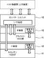
図4は、本発明の一実施形態に係る中継器43の構成を示している。同図に示すように、中継器43は、その内部にシステム回路を含み、具体的には、プロセッサコア431と、メモリ432と、外部インターフェース433と、ポート434、スイッチング機構435と、バッファメモリ436a及び436bと、を備え、これらは機能的に接続されている。 FIG. 4 shows the configuration of the
プロセッサコア431は、メインメモリとして機能するメモリ432に格納された所定の制御シーケンスに従って、中継器43を統括的に制御する。例えば、プロセッサコア431は、SAS/SATAプロトコル上のコマンドを解釈し、次段の機器(例えば、コントローラユニット42又はディスクデバイス41)に当該コマンドを引き渡す。 The
メモリ432は、システム構成情報やポート管理テーブル等のプロファイルを保持する。プロセッサコア431は、例えば、電源投入時または再起動時に、初期シーケンスを通して、ポート434に接続される各種の機器(ディスクデバイス41等)を検出し、検出されたディスクデバイス41との間の通信に適したプロトコルを決定して、これをシステム構成情報の一部としてメモリ432に保持する。例えば、アウト・オブ・バンド(OOB;Out Of Band)信号を利用して、ポートに接続された周辺機器がSASディスクデバイス41aであるか、SATAディスクデバイス41bであるかを判定することができる。OOB信号は、機器間のハンドシェイク用のプリミティブなパルス信号として知られている。システム構成情報は、後述するように、省電力制御に関するパワーマネージメントパラメータを含む。ポート管理テーブルは、各ポートに与えられる状態パラメータである。ポート管理テーブルにおける状態パラメータのいくつかは、制御シーケンスによって自動的に検出され、他のいくつかは、ネットワークシステム3又は外部I/F426を介して、管理端末5上のユーザから与えられる。 The
図5は、本発明の一実施形態に係る中継器43におけるポート管理テーブルの一例を示す図である。ポート管理テーブルは、例えば、プロセッサコア431の制御の下、中継器43の電源投入時または起動時に、初期シーケンスの実行を通してメモリ432上に配置される。 FIG. 5 is a diagram showing an example of a port management table in the
すでに述べたように、本実施形態の中継器43は、32個のポート434を持っており、これらのポート434は、ポート番号によって一意に識別される。各ポート434は、接続タイプ、接続区分、インターフェース種別、動作状態、移行日付、移行時刻、I/O量/分、移行待ち時間、及び遷移テーブルに関する情報を含んでいる。同図において、例えば、ポート番号「1」は、2006年XX月14日の6:30:00に現在のActiveに移行したが、I/O量が0となってから0:00:30経過したことを示している。中継器43は、ポート管理テーブルを参照して、例えば、ポート434に接続されたディスクデバイス41の動作状態(省電力モードであるかまたは通常モードであるか)を取得することができる。As already described, the
図4に戻り、外部インターフェース433は、中継器43をコントローラユニット42(図2)のディスクインターフェース424と接続するためのインターフェースである。外部インターフェース433はプロセッサコア431に接続されている。 Returning to FIG. 4, the
ポート434は、ディスクデバイス41をポイント・ツー・ポイント方式で接続するためのインターフェースである。各ポート434には、ユニークなポート番号が割り当てられる。本実施形態では、32個のポート434が提供されており、各ポート434に0〜31のポート番号が割り当てられている。 The
スイッチング機構435は、外部インターフェース433とポート434との間におけるデータ通信パスを選択的に一意に確立するためのスイッチ素子と、パスの確立が競合した場合に調停を図るアービタとを含んでいる。 The
バッファメモリ436aは、不揮発性メモリにより構成されている。バッファメモリ436aは、バッファメモリ436aは、アービタによって調停され、確立を他のパスに譲ったパスのデータを一時的に保持する。これに対して、バッファメモリ436bは、揮発性メモリにより構成されている。バッファメモリ436a及び/または436bは、中継器43におけるキャッシュメモリとしても利用されるかもしれない。 The
図6は、本発明の一実施形態に係る中継器43に対する設定処理を説明するためのシーケンス図である。中継器43に対する設定処理は、典型的には、管理端末5上のユーティリティツールからコントローラユニット42を介して行われる。ユーティリティツールは、ある種の管理プログラムであり、システム管理者がインタラクティブに各種のパラメータを設定できるように、ユーザインターフェースを提供する。 FIG. 6 is a sequence diagram for explaining the setting process for the
図7は、本発明の一実施形態に係る管理端末5上のユーティリティツールが提供するユーザインターフェースの一例を示している。同図に示すように、システム管理者は、管理端末5上のシステムマネージャを用いて、ストレージ装置4に対するパワーマネージメントパラメータを設定する。本実施形態では、パワーマネージメントパラメータは、「アクセス待機時間」、「最小駆動台数」、「再起動間隔」、及び「全体のI/Oアクセス量」に関するパラメータからなる。「アクセス待機時間」は、直近のI/Oアクセスがあった時点から起算して次のI/Oアクセスを受け取るまで待機する時間である。つまり、I/Oアクセスが途絶えてから許容される時間である。「最小駆動台数」は、中継器4に接続され、配下にあるディスクデバイス41が、最低限、駆動している台数である。ストレージ装置4の稼働中、駆動中のディスクデバイス41の台数は、当該最小駆動台数を下回ることはない。「再起動間隔」は、一旦、ディスクデバイス41を省電力モードに移行させた時点から、I/Oアクセス要求とは無関係に、通常モードに移行させるまでの時間間隔である。「全体のI/Oアクセス量」は、他の中継器43に転送されるI/Oアクセス要求を除く、ディスクデバイス41が接続された有効なポート434におけるI/Oアクセス量(I/Oトラフィック量)の合計値である。または、当該合計値を有効なポート434の総数で割った商(ポート当たりの平均I/Oアクセス量)であってもよい。または、「アクセス待機時間」の何パーセントというように、設定値を動的に変化させてもよい。 FIG. 7 shows an example of a user interface provided by the utility tool on the
ユーティリティツールは、設定されたパラメータを受け付けると、所定の通信プロトコルに従い、例えばHTTPに従い当該パラメータの設定要求を、ストレージ装置4のコントローラユニット42に送出する。 Upon receiving the set parameter, the utility tool sends a parameter setting request to the
図6に戻り、管理端末5からパラメータを受け付けたコントローラユニット42は、CPU421の制御の下、ディスクインターフェース424を介して、当該パラメータを対応する中継器43に引き渡す。コントローラユニット42と各中継器43とは、SMPに従って通信を行う。中継器43から正常終了メッセージを受け取ると、コントローラユニット42は、当該中継器43に対する設定が完了したものと認識する。コントローラユニット42は、各中継器43との間で通信を行って、受け付けたパラメータに対するすべての中継器43の設定を行う。コントローラユニット42は、すべての中継器43の設定が完了すると、設定完了通知を管理端末5に送出する。ユーティリティツールは、設定完了通知を受け取ると、これをシステム管理者に提示する。 Returning to FIG. 6, the
図8は、本発明の一実施形態に係る中継器43におけるシステム構成情報の一例を示す図である。中継器43は、コントローラユニット42を介して、管理端末5からパワーマネージメントパラメータの設定要求を受け取ると、これをシステム構成情報の一部として、メモリ432に格納する。パワーマネージメントパラメータは、上述したように、例えば、「アクセス待機時間」、「最小駆動台数」、「再起動間隔」、及び「全体のI/Oアクセス量」に関するパラメータからなる。このパワーマネージメントパラメータは、以下に説明されるような、ディスクデバイス41の動作制御の処理シーケンスにおいて参照される。 FIG. 8 is a diagram showing an example of system configuration information in the
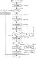
図9は、本発明の一実施形態に係るストレージ装置4におけるディスクデバイス41に対する制御を示すフローチャートである。具体的には、図9は、中継器43による、省電力モード移行条件に合致するディスクデバイス41に対する停止制御を説明している。中継器43は、省電力モード移行条件に合致するディスクデバイス41を検出するため、各ポート434を並列的に監視する。 FIG. 9 is a flowchart showing the control for the
中継器43は、省電力モードに移行すべきディスクデバイス41を検出するため、各ポート434を定期的にスキャンしている。省電力モードへの移行は、基本的には、コントローラユニット42から一定時間以上アクセスがないディスクデバイス41に対して行われる。本実施形態では、中継器43は、パワーマネージメントパラメータにおける最小駆動台数パラメータで指定された台数以上のディスクデバイス41が通常モードで稼働するように、ディスクデバイス41の省電力モードへの移行を制御する。したがって、すでに最小駆動台数パラメータで指定された台数のディスクデバイス41が駆動している場合には、省電力モードに移行しているディスクデバイス41の中から、通常モードに戻すべきディスクデバイス41を選択し、これらを入れ替える。例えば、省電力モードに移行したディスクデバイス41のうち、コントローラユニット42からのアクセスがない状態が継続していても、再起動間隔パラメータで指定された時間を超えているディスクデバイス41については、中継器43は、診断のため、当該ディスクデバイス41を通常モードに移行し、これと入れ替えで、一定時間以上アクセスがないとして検出されたディスクデバイス41を省電力モードに移行させる。 The
より具体的には、図9に示すように、中継器43は、各ポート434について、一定量以上のI/Oアクセスがあるか否かを判断する(STEP901)。ここでは、ディスクデバイス41が接続された有効なポート434におけるI/Oアクセス量の合計値を有効なポート434の総数で割った値が所定値以上であるか否かが判断される。有効なポートとは、中継器43の配下のディスクデバイス41を接続しているポートである。中継器43の配下に接続されたディスクデバイス41に一定量以上のアクセスがあると判断される場合(STEP901の“Yes”)、パワーマネージメントパラメータを第1の値に設定し(STEP902)、これに対して、一定量以上のアクセスがないと判断される場合(STEP901の“No”)、パワーマネージメントパラメータを第2の値に設定する(STEP902)。第1の値及び第2の値は、ここでは、アクセスが途絶えてから経過時間を示している。例えば、第1の値には「5分」が設定され、第2の値にはそれよりも短い時間として「3分」が設定される。パワーマネージメントパラメータにおける各パラメータのセットを複数のテーブルとして保持し、それらを切り替えるように設定してもよい。 More specifically, as shown in FIG. 9, the
中継器43は、次に、コントローラユニット42からのアクセスが途絶えてから上記設定した時間以上経過したか否かをチェックする(STEP904)。一定時間以上アクセスがないと判断した場合(STEP904の“Yes”)、中継器43は、さらに、現在、通常モードにあるディスクデバイス41の台数が最小駆動台数に等しいか否かをチェックする(STEP905)。最小駆動台数に等しくない場合、つまり、ディスクデバイス41を追加的に省電力モードに移行させることができる場合(STEP905の“Yes”)、当該ポート434を選択して(STEP906)、当該ポート434に接続されたディスクデバイス41に対してモータ停止コマンド(スピンオフコマンド)を送出する(STEP907)。 Next, the
上述したように、中継器43とディスクデバイス41との間の通信は、デバイスの種類に依存したプロトコルに従って行われ、また、モータ停止コマンド等のデバイスに対するコマンドは、ディスクデバイス41の種類に依存している。図10は、本発明の一実施形態に係る中継器43によって発行されるSAS/SATAコマンドを例示している。したがって、同図に示すように、中継器43は、SASディスクデバイス41aに対しては“Unit Stop”コマンドを送出し、SATAディスクデバイス41bに対しては“SLEEP”コマンドを送出する。 As described above, communication between the
一方、通常モードにあるディスクデバイス41の台数がすでに最小駆動台数に達していると判断した場合(STEP905の“No”)、中継器43は、再起動時間に達しているディスクデバイス41があるか否かを判断する(STEP908)。再起動時間に達しているディスクデバイス41がある場合(STEP908の“Yes”)、当該再起動時間に達しているディスクデバイス41を通常モードに移行させるため、起動処理を行う(STEP909)。なお、ディスクデバイス41に対する起動処理の詳細については、後述する。当該ディスクデバイス41を起動させることによって、駆動中の台数が最小駆動台数よりも多くなることから、中継器43は、当該ポートのディスクデバイス41を選択し(STEP906)、省電力モードへ移行させる(STEP907)。 On the other hand, if it is determined that the number of
図11は、本発明の一実施形態に係るストレージ装置4におけるディスクデバイス41によるモータ停止制御を説明している。 FIG. 11 illustrates motor stop control by the
上述した図9のSTEP904におけるモータ停止コマンドの発行に応答して、ディスクデバイス41は、中継器43からスピンオフコマンドを受け取ると(STEP1101)、正常終了ステータスを中継器43に送出するとともに(STEP1102)、通常モードから省電力モードに切り替えるため、スピンドルモータの駆動を停止させる(STEP1103)。中継器43は、ディスクデバイス41から正常終了ステータスを受け取ると、中継器43は、省電力モード移行条件に合致したディスクデバイス41が正常に停止したことを認識する。 In response to the issuance of the motor stop command in
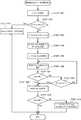
図12は、本発明の一実施形態に係るストレージ装置におけるディスクデバイスに対する制御を示すフローチャートである。具体的には、図12は、中継器43によるディスクデバイス41に対する起動制御(省電力モードから通常モードへの移行制御)を説明している。 FIG. 12 is a flowchart showing control on the disk device in the storage apparatus according to an embodiment of the invention. Specifically, FIG. 12 illustrates activation control (transition control from the power saving mode to the normal mode) for the
同図に示すように、中継器43は、各ポート434について、通常モード移行条件に合致したか否かを監視している(STEP1201A)。具体的には、コントローラユニット42から受け取ったI/Oアクセス要求(I/Oコマンド)が省電力モードにあるディスクデバイス41に対するI/Oアクセス要求であるか、または既述した図9において再起動されることになったディスクデバイス41がある場合に、合致したものと判断される。 As shown in the figure, the
通常モード移行条件に合致したポート434がある場合(STEP1201Aの“Yes”)、中継器43は、当該ポート434に接続されたディスクデバイス41に対して、そのモータを起動させるために、スピンアップコマンドを送出する(STEP1202A)。つまり、中継器43は、図10に示したように、SASディスクデバイス41であれば、“Unit Start”コマンドを送出する。また、SATAディスクデバイス41であれば、“DEVICE RESET”コマンド及び“IDLE IMMEDIATE”コマンドを送出する。 If there is a
ディスクデバイス41は、中継器43からスピンアップコマンドを受け取ると(STEP1201B)、正常終了ステータスを中継器43に送出するとともに(STEP1202B)。省電力モードから通常モードに切り替えるため、スピンドルモータを起動させる(STEP1203B)。これにより、中継器43は、パワーマネージメントパラメータに合致したディスクデバイス41のスピンドルモータが正常に起動したことを認識する。 When the
次に、中継器43は、ReadyCheckコマンドを当該ディスクデバイス41に対して送出する(STEP1203A)。これは、ディスクデバイス41のスピンドルモータが定常速度に達したか否かをチェックするためである。ディスクデバイス41は、スピンドルモータが定常速度に達し、起動が完了したことを検出すると(STEP1204B)、起動完了レポートを中継器43に送出する。中継器43は、当該起動完了レポートを受け取るまで、RedayCheckコマンドを発行する(STEP1204A)。 Next, the
中継器43は、当該起動完了状態を検出すると(STEP1204Aの“Yes”)、コントローラユニット42から当該ディスクデバイスに対するI/Oコマンドを受け取っているか否かを判断する(STEP1205A)。I/Oコマンドを受け取っている場合(STEP1205Aの“Yes”)、当該I/Oコマンドをデバイスディスクに送出する(STEP1206A)。ディスクデバイス41は、I/Oコマンドを受け取ると、I/Oコマンドに基づいた処理を行う(STEP1205B)。 When the
コントローラユニット42からディスクデバイス41に対するI/Oアクセス要求を受け取る中継器43は、コントローラユニット42側のコマンドタイムアウトを考慮して設計される。 The
I/Oアクセス要求が読み込み要求コマンドである場合において、コントローラユニット42側(ホスト装置2上のOS/アプリケーションプログラムを含む。)におけるコマンド(セッション)タイムアウトが、ディスクデバイス41の起動所要時間よりも十分に長く設定されている場合には、中継器43は、当該読み込み要求コマンドをバッファメモリ436aに一時的に保持し、起動完了レポートを受け取った時点で、当該読み込み要求コマンドを送出する。コマンドタイムアウトが短い場合には、中継器43は、コントローラユニット42にリトライを促し、または通信セッションを維持するために所定のメッセージを送出する。 When the I / O access request is a read request command, the command (session) timeout on the
I/Oアクセス要求が、省電力モードにあるディスクデバイス41に対する書き込み要求コマンドである場合、当該ディスクデバイス41が起動するまでに所定の時間を要するため、書き込み処理に遅延が発生するおそれがある。したがって、当該書き込み要求コマンド及びこれに関連付けられた書き込み対象データを確実に保持しておくための遅延書き込みデータの保護メカニズムが必要になる。このようなメカニズムとして、例えば;(1)コントローラユニット42のキャッシュメモリを用いたデータ保護;(2)中継器43の不揮発性バッファメモリ436aを用いたデータ保護;及び(3)中継器43に接続された外部ストレージを利用したデータ保護が考えられる。さらに、外部ストレージを用いたデータ保護については、(3−1)中継器43に接続されたディスクデバイス41の一部の利用及び(3−2)中継器43に外付けで装着された不揮発性記憶デバイスの利用が考えられる。 When the I / O access request is a write request command for the
ここでは、コントローラユニット42のキャッシュメモリを用いたデータ保護方式について説明する。当該保護方式においては、コントローラユニット42は、ディスクデバイス41から書き込み要求コマンドに対する正常終了ステータスを受け取るまで書き込み要求コマンドに関連付けられた書き込み対象データをキャッシュメモリから解放しないように、設計される。この場合、駆動中のディスクデバイス41については、中継器43がコントローラユニット42に対して所定のメッセージを送出する。または、スピンドルモータが起動され、ディスクデバイス41がアクセス可能になる時間が経過した後、中継器43が、コントローラユニット42からのコマンドをディスクデバイス41に転送し、ディスクデバイス41から送出されてくるであろうNotReadyステータスに対して、コントローラユニット42がリトライするようにしてもよい。 Here, a data protection method using the cache memory of the
図13は、本発明の一実施形態に係る中継器43の動作を説明するためのフローチャートである。なお、ここでは、対象となるポート434に接続されたディスクデバイス41がSASディスクデバイスであるものとして説明する。 FIG. 13 is a flowchart for explaining the operation of the
まず、ホスト装置2から書き込み要求コマンドがストレージ装置4に送出されると、コントローラユニット42は、キャッシュ機構423の作用により、当該コマンドに関連付けられた書き込み対象データをキャッシュメモリ上に一時的に格納するとともに、当該書き込み対象データをディスクデバイス41に書き込むために、当該コマンド(書き込み対象データを含む。)を中継器43に送出する。 First, when a write request command is sent from the
中継器43は、同図に示すように、コントローラユニット42から書き込み要求コマンドを受け取ると(STEP1301)、これをバッファメモリ436aにキャッシュ可能か否かをチェックする(STEP1302)。中継器43は、キャッシュ可能であると判断する場合(STEP1302の“No”)、書き込み要求コマンドをバッファメモリ436aに格納する(STEP1303)。なお、バッファメモリ436aが満杯であり、このためキャッシュ可能でない場合には、中継器43は、Queue Fullステータスをコントローラユニット42に送出する(STEP1315)。 As shown in the figure, when the
中継器43は、次に、コントローラユニット42に対してDisconnetメッセージを送出することにより(STEP1304)、コントローラユニット42に対して当該ディスクデバイスに41が起動中であることを通知し、コマンドシーケンスを一時的に保留する。これにより、コントローラ42は、タイムアウト時間を延長することができる。併せて、中継器43は、書き込み対象となっているディスクデバイス41のスピンドルモータを起動させるために、当該ディスクデバイス41に対してモータ起動コマンド“Unit Start”コマンドを送出する(STEP1305)。当該モータ起動コマンド“Unit Start”を受け取ったディスクデバイス41は、上述した起動処理を行う。 Next, the
中継器43は、当該ディスクデバイス41から正常終了ステータスを受け取ると、当該ディスクデバイス41に対してReadyCheckコマンド“Test Unit Ready”を送出し(STEP1306)、起動が完了したか否かを判断する(STEP1307)。中継器43は、ディスクデバイス41から起動完了レポートを受け取るまで、ReadyCheckコマンドを送出し続けるが、一定時間が経過した時点で、起動完了であるものとみなして、次の処理に進む(STEP1308の“Yes”)。 When receiving the normal end status from the
起動完了メッセージを受け取った場合、または一定時間が経過した場合、中継器43はさらに、ディスクデバイス41に対して書き込み要求コマンドを送出する(STEP1309)。これを受けて、ディスクデバイス41は、書き込み処理を行い、書き込み処理が正常に終了した場合には、書き込み完了ステータスを中継器43に送出する。 When the activation completion message is received or when a predetermined time has elapsed, the
中継器43は、書き込み完了ステータスを受け取った場合(STEP1310の“Yes”)、コントローラユニット42に対してReconnectメッセージを送出する(STEP1311)。これにより、中継器43は、コントローラユニット42に対して保留していたコマンドシーケンスを進行させる。そして、一連のコマンドの実行が終了すると、中継器43は、コントローラユニット42に対して正常終了ステータスを送出する(STEP1312)。コントローラユニット42は、当該正常終了ステータスを受け取ると、キャッシュメモリ上の当該書き込み対象データを記憶していた領域を開放する。 When receiving the write completion status (“Yes” in STEP 1310), the
このように、本実施形態では、コントローラユニット42のキャッシュメモリに書き込み対象データを一時的に保持しているので、停電等の不測の事態等によりデータの書き込みに失敗した場合であっても、書き込み対象データの消失を防ぐことができる。特に、本実施形態では、Disconnect/Reconnectを用いて、コマンドシーケンスを中断/再開している。したがって、コマンドシーケンスが終了しない限り、コントローラユニット42は、キャッシュ領域を開放しないので、書き込み対象データの消失を防ぐことができるようになる。 As described above, in this embodiment, since the write target data is temporarily held in the cache memory of the
一方、中継器43は、一定時間内に書き込み完了ステータスを受け取ることができなかった場合(STEP1310の“No”)、中継器は、まず、コントローラユニット42に対してReconnectメッセージを送出した後(STEP1313)、コントローラユニット42に対してチェックコンディションステータスを送出して、処理を終了する。チェックコンディションステータスは、ディスクデバイス41からのエラー報告である。この場合、コントローラユニット42は、キャッシュメモリ上の領域を解放することなく、再度、書き込み要求コマンドを送出するかも知れない。 On the other hand, if the
なお、本実施形態では、中継器43において書き込み要求コマンドをキャッシュするために不揮発性のバッファメモリ436aを用いたが、揮発性のバッファメモリ436bを用いるようにしてもよい。
(変形例1)
次に、中継器43の不揮発性バッファメモリ436aを用いた遅延書き込みデータの保護メカニズム(上記(2)に対応する。)について説明する。In the present embodiment, the
(Modification 1)
Next, a delayed write data protection mechanism (corresponding to the above (2)) using the
図14は、本発明の一実施形態に係る中継器43の動作を説明するためのフローチャートである。なお、ここでは、対象となるポート434に接続されたディスクデバイス41がSASディスクデバイスであるものとして説明する。 FIG. 14 is a flowchart for explaining the operation of the
上述の実施形態と同様に、ホスト装置2から書き込み要求コマンドがストレージ装置4に送出されると、コントローラユニット42は、キャッシュ機構423の作用により、当該コマンドに関連付けられた書き込み対象データをキャッシュメモリ上に一時的に格納するとともに、当該書き込み対象データをディスクデバイス41に書き込むために、当該コマンド(書き込み対象データを含む。)を中継器43に送出する。 Similar to the above-described embodiment, when a write request command is sent from the
中継器43は、同図に示すように、コントローラユニット42から書き込み要求コマンドを受け取ると(STEP1401)、これをバッファメモリ436aにキャッシュ可能か否かをチェックする(STEP1402)。中継器43は、キャッシュ可能であると判断する場合(STEP1402の“No”)、書き込み要求コマンドに関連付けられた書き込み対象データをバッファメモリ436aに格納する(STEP1403)。なお、バッファメモリ436aが満杯であり、このためキャッシュ可能でない場合には、中継器43は、Queue Fullステータスをコントローラユニット42に送出する(STEP1413)。 As shown in the figure, when the
中継器43は、次に、コントローラユニット42に対して正常終了ステータスを送出する(STEP1404)。これにより、コントローラユニット42は、キャッシュメモリ上の当該書き込み対象データに関する領域を開放する。つまり、本実施形態では、Disconnectメッセージを用いて、一旦、コマンドシーケンスを中断するのではなく、中継器43が書き込み要求コマンドに関連付けられた書き込み対象データをバッファメモリ436aにキャッシュした時点で、正常終了ステータスをコントローラユニット42に返し、コントローラユニット42上のキャッシュメモリ領域を開放する。このため、データの喪失を防ぐ観点から、中継器43は、書き込み要求コマンドをバッファメモリ436aにキャッシュすることが好ましい。 Next, the
続いて、中継器43は、書き込み対象となっているディスクデバイス41のスピンドルモータを起動させるために、当該ディスクデバイス41に対してモータ起動コマンド“Unit Start”を送出する(STEP1405)。当該モータ起動コマンド“UnitStart”を受け取ったディスクデバイス41は、前述した起動処理を行う。 Subsequently, the
中継器43は、当該ディスクデバイス41から正常終了ステータスを受け取ると、当該ディスクデバイス41に対してReadyCheckコマンド“Test Unit Ready”を送出し(STEP1406)、起動が完了したか否かを判断する(STEP1407)。中継器43は、ディスクデバイス41から起動完了レポートを受け取るまで、当該ReadyCheckコマンドを送出し続けるが、一定時間が経過した時点で、起動完了であるものとみなして、次の処理に進む(STEP1408の“Yes”)。 When receiving the normal end status from the
起動完了レポートを受け取った場合、または一定時間が経過した場合、中継器43はさらに、ディスクデバイス41に対して書き込み要求コマンドを送出する(STEP1409)。これを受けて、ディスクデバイス41は、書き込み処理を行い、書き込み処理が正常に終了した場合には、書き込み完了ステータスを中継器43に送出する。 When the activation completion report is received or when a predetermined time has elapsed, the
中継器43が書き込み完了ステータスを受け取った場合には(STEP1410の“Yes”)、書き込み要求コマンドに対する一連の処理が正常に終了することを意味するが、一定時間内に書き込み完了ステータスを受け取ることができなかった場合には(STEP1410の“No”)、中継器43は、次回の当該ディスクデバイス41に対するコマンドを契機に、コントローラユニット42に対してチェックコンディションステータスを送出して、処理を終了する。
(変形例2)
次に、中継器43に接続された外部ストレージを用いた遅延書き込みデータの保護メカニズム(上記(3)に対応する。)について説明する。遅延書き込みデータを保護するためには、比較的容量が大きなメモリが必要とされるので、以下の変形例では、中継器43に接続された外部ストレージにキャッシュするように構成している。なお、ここでいう外部ストレージは、例えば、中継器43に接続されたディスクデバイス41上に形成される特定の領域であってもよいし、または中継器43に外的に装着可能な記憶デバイスであってもよい。外的に装着可能な記憶デバイスとしては、例えば、単体として独立し、ケーブル等で接続される記憶デバイスでもよいし、スロット装着されるカード型メモリデバイスでもよい。記憶媒体がメモリである場合には、不揮発性であることが望ましい。When the
(Modification 2)
Next, a delayed write data protection mechanism (corresponding to (3) above) using an external storage connected to the
図15は、本発明の一実施形態に係る中継器43の動作を説明するためのフローチャートである。これは、上記(3−1)に対応する。なお、当該フローチャートにおいても、対象となるポート434に接続されたディスクデバイス41がSASディスクデバイスであるものとして説明する。 FIG. 15 is a flowchart for explaining the operation of the
遅延書き込みデータの保護メカニズムとして、上述したように、(3−1)中継器43に接続されたディスクデバイス41のうち、通常モードで動作しているディスクデバイス41の一部の記憶領域を外部ストレージに利用する方法、及び(3−2)中継器43に外付けで装着された不揮発性の記憶デバイスを利用する方法がある。前者の場合、遅延書き込みデータの実体は、外部ストレージに一時的に格納され、当該データのメタデータについては、中継器43に設けられた不揮発性のバッファメモリ436aに一時的に格納される。後者の場合、当該データの実体は、外付けの記憶デバイスに格納されるが、メタデータの一部または全部は、当該外付けの記憶デバイスに格納されてもよい。 As a protection mechanism for delayed write data, as described above, (3-1) among the
本実施形態では、中継器43に接続されている外部ストレージにデータの実体を一時的に格納するとともに、メタデータを中継器43に設けられた不揮発性のバッファメモリ436aに格納する。 In the present embodiment, the substance of data is temporarily stored in an external storage connected to the
上述の実施形態と同様に、ホスト装置2から書き込み要求コマンドがストレージ装置4に送出されると、コントローラユニット42は、キャッシュ機構423の作用により、当該コマンドをキャッシュメモリ上に一時的に格納するとともに、当該コマンドの書き込み対象データをディスクデバイス41に書き込むために、当該コマンドに対応する内部的なコマンドを中継器43に送出する。なお、本明細書では、明確に特に区別する必要がない限り、便宜上、単にコマンドと総称することもある。 As in the above-described embodiment, when a write request command is sent from the
これを受けて、中継器43は、同図に示すように、コントローラユニット42から書き込み要求コマンドを受け取ると(STEP1501)、当該コマンドを解釈して、対象となるディスクデバイス41が通常モードであるか否かをチェックする(STEP1502)。中継器43は、対象となるディスクデバイス41が通常モードであると判断する場合(STEP1502の“Yes”)、当該コマンドを当該ディスクデバイス41に転送する(STEP1503)。これを受けて、当該ディスクデバイス41は、書き込み処理を行い、書き込みが正常に終了すると、正常終了ステータスを中継器43に送出する。 In response to this, when receiving a write request command from the controller unit 42 (STEP 1501), the
一方、対象となるディスクデバイス41が通常モードではないと判断する場合(STEP1502の“No”)、中継器43は、外部ストレージに十分な書き込みスペースがあるか否かをチェックする(STEP1504)。当該チェックは、書き込み要求コマンドにおける書き込み対象データ長と外部ストレージの空き容量とを比較することにより行われる。外部ストレージに関するプロファイルは、例えば、上述したシステム構成情報の一部としてメモリ432に格納される。 On the other hand, if it is determined that the
図16は、本発明の一実施形態に係る中継器43のメモリ432に格納されたシステム構成情報の一例を示している。システム構成情報は、後述するメタデータテーブルに対するポインタを含む。また、システム構成情報は、どのポート434に接続されたディスクデバイス41が通常モードであるかを示すポートリストを含んでいる。ポートリストは、例えば、当該ポート434のポート番号、外部ストレージとして定義された現在の空き容量、最小値、及び最大値を含む。ここで、外部ストレージの最小値とは、論理ブロックの最小単位に対応している。外部ストレージとしての領域には、先頭アドレス及び割当容量が指定される。これにより、コントローラユニット42は、中継器43ごとに外部ストレージにおける領域の先頭アドレスを排他的に認識する。 FIG. 16 shows an example of system configuration information stored in the
比較の結果、空き容量がないと判断される場合(STEP1504の“Yes”)、中継器43は、コントローラユニット42に対してQueue Fullステータスを送出し(STEP1514)、処理を終了する。 As a result of the comparison, when it is determined that there is no free space (“Yes” in STEP 1504), the
これに対して、空き容量がある場合(STEP1504の“No”)、中継器43は、書き込み要求コマンドが示す書き込み先アドレスを外部ストレージの空き領域の先頭アドレスに変換した後(STEP1505)、書き込み対象データを外部ストレージに送出する(STEP1506)。これを受けて、例えば、外部ストレージとしてディスクデバイス41の一部を利用している場合には、ディスクデバイス41は、書き込み処理を行い、書き込みが正常に終了すると、正常終了ステータスを中継器43に送出する。中継器43はまた、当該書き込み対象データに関するメタデータをバッファメモリ436aに格納する(STEP1507)。図17は、本発明の一実施形態に係る中継器43に格納されるメタデータテーブルの一例を示している。同図に示すように、メタデータは、各シーケンス番号により一意に識別され、管理されている。シーケンス番号は、I/Oアクセス要求ごとに割り当てられる番号である。論理ブロックアドレス(LBA)は、ディスクデバイス41における外部ストレージとして割り当てた先頭アドレスを示している。 On the other hand, when there is a free capacity (“No” in STEP 1504), the
図15に戻り、中継器43は、次に、コントローラユニット42に対して正常終了ステータスを送出する(STEP1508)。これを受けて、コントローラユニット42は、キャッシュメモリ上の書き込み要求コマンドを記憶していた領域を開放する。さらに中継器43は、ディスクデバイス41に対してモータ起動コマンドを送出し、ディスクデバイス41から正常終了ステータスの報告を待つ(STEP1509)。 Returning to FIG. 15, the
ディスクデバイス41から正常終了ステータスの報告を受けると、中継器43は、バッファメモリ436aに格納しておいた当該書き込み要求コマンドに対応するメタデータを読み出して、読み出したメタデータに基づいて、外部ストレージに退避してある書き込み対象データを読み出す(STEP1510)。外部ストレージとしてディスクデバイス41の一部を利用している場合、通常の読み込み要求コマンドを用いる。読み込み要求コマンドに応答したディスクデバイス41は、書き込み対象データを読み出して、終了ステータスとともに中継器43に送出する。 When receiving the report of the normal end status from the
中継器43は、外部ストレージから読み出された書き込み対象データを、本来の書き込み対象となっているディスクデバイス41に格納する(STEP1511)。書き込み要求コマンドに応答したディスクデバイス41は、書き込み対象データを所定の領域に書き込み、中継器43に対して正常終了ステータスを報告する。中継器43は、正常終了ステータスを受け取ると、バッファメモリ436a上のメタデータを記憶している領域を開放する(STEP1512)。そして、中継器43は、外部ストレージに待避しているすべての書き込み対象データの移行を完了したか否かを判断し(STEP1513)、まだ移行が完了していないデータがあれば(STEP1513の“No”)、STEP1510に戻る。
(変形例3)
図18は、本発明の一実施形態に係るストレージ装置の構成を示す図である。具体的には、書き込み遅延データの保護メカニズムとして、外付けの不揮発性記憶デバイスを含むストレージ装置が示されている。これは、上記(3−2)に対応する。The
(Modification 3)
FIG. 18 is a diagram showing a configuration of a storage apparatus according to an embodiment of the present invention. Specifically, a storage apparatus including an external nonvolatile storage device is shown as a protection mechanism for write delay data. This corresponds to the above (3-2).
同図に示すように、コントローラユニット42には2台の中継器43が接続され、さらに、各中継器43を介して他の中継器43が接続されている。各中継器43のポート(図示せず)には、SASディスクデバイス群41a及びSATAディスクデバイス群41bが接続され、ディスクデバイス41の階層的な利用が可能になっている。中継器43は、前述したように、メモリ432を備え、システム構成情報等のプロファイルを保持している。また、中継器43は、不揮発性のバッファメモリ436aに、例えば、図19に示すようなメタデータテーブルを保持する。 As shown in the figure, two
ストレージ装置4は、共用外部ストレージ44が設けられ、各中継器43は、外部ストレージ44に接続されている。共用外部ストレージ44は、不揮発性のメモリを含んでおり、中継器43からのアクセス要求に応じて書き込み及び読み出し処理が可能なように構成されている。共用外部ストレージ44は、例えば、ストレージ装置4の筐体に設けられたスロットに装着され、各中継器43とは、専用ケーブルで接続される。共用外部ストレージ44は、各中継器43に割り当てられた記憶領域181a,181b,181c,..が設定されている。 The
以上のような構成を有するストレージ装置4において、各中継器43は、共用外部ストレージ44を用いて、ディスクデバイス41に対する省電力制御を行う。すなわち、前述したように、省電力モードにあるディスクデバイス41に対して書き込み要求コマンドが送出されてきた場合、中継器43は、ディスクデバイス41が省電力モードから通常モードに移行させるまでの間、書き込み対象データを、一旦、外部ストレージ44に退避させることにより、遅延が発生した書き込み対象データが喪失しないように保護を図る。 In the
これにより、中継器43は、その内部に大容量の不揮発性メモリを有する必要がなく、システム設計の自由度を高めることができる。したがって、RAIDグループの構成台数比率に応じて、記憶容量の割り当てを任意に変更することができる。または、ディスクデバイス41に正副のボリュームを形成する場合であっても、記憶容量の割り当てを任意に変更することができる。 Thereby, the
正副のボリュームを形成した構成において、中継器43に設けられたタイマーに従って周期的に同期処理を行う場合、中継器43は、当該同期処理に合わせて、副ボリュームのディスクデバイス41を通常モードに移行し、一定時間が経過した後、当該ディスクデバイス41を省電力モードに移行させるようにしてもよい。中継器43の各ポート434にそのような省電力制御設定を行うことができるため、RAID構成に応じた自由度の高い設計ができるようになる。
[第2の実施形態]
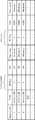
次に、本発明の第2の実施形態について説明する。本実施形態は、中継器43内のシステム回路の規模を小さくし、かつ、さらに効率のよい省電力制御を可能にするものである。このため、本実施形態に係るストレージ装置4においては、パワーマネージメント・オーダード・セット乃至はプリミティブが新たに提供される。なお、ストレージ技術の規格によって、オーダード・セット乃至はプリミティブ等の呼称が用いられるが、ここでいうオーダード・セットは、これらを含めた広い意味で用いている。In the configuration in which the primary and secondary volumes are formed, when the synchronization process is periodically performed according to the timer provided in the
[Second Embodiment]
Next, a second embodiment of the present invention will be described. In the present embodiment, the scale of the system circuit in the
図20は、本発明の一実施形態に係るストレージ装置4におけるオーダード・セットを例示している。上述した図10に示したSAS/SATAコマンドと比較することで、SAS/SATAコマンドとの対応関係が理解される。
Figure 20 illustrates the Orderedset in the
本実施形態においては、シリアルデータ転送技術において一般的に採用されている8b/10bエンコーディング方式を採用する。8b/10bエンコーディング方式では、8ビットデータを10ビットデータに変換することにより、もとのデータ以外のデータを送信することができる。 In this embodiment, the 8b / 10b encoding method generally employed in the serial data transfer technique is employed. In the 8b / 10b encoding method, data other than the original data can be transmitted by converting 8-bit data into 10-bit data.
8ビットデータは、下位5ビットと上位3ビットとの組み合わせからなるコードグループ(表記上、文字“D”で始まる。)として定義される。当該エンコーディング方式により8b/10b変換されたデータは10ビットとなり、当該10ビットの単位データ4つを集めた40ビットの列の組み合わせによりオーダード・セットが定義される。オーダード・セットは、図21(a)及び(b)に示すように、文字“K”で始まる10ビットの特殊符号グループで始まる。本実施形態では、SASディスクデバイス41aに対するオーダード・セットは、例えば“K28.5”に基づき、SATAディスクデバイス41bに対するオーダード・セットは、例えば“K28.3”に基づいて定義される。 The 8-bit data is defined as a code group (starting with the letter “D” for notation) consisting of a combination of lower 5 bits and upper 3 bits. Data converted by 8b / 10b by the encoding method becomes 10 bits, and an ordered set is defined by a combination of 40-bit columns obtained by collecting four 10-bit unit data. The ordered set begins with a 10-bit special code group that begins with the letter “K”, as shown in FIGS. In this embodiment, the ordered set for the
このようなオーダード・セット体系において、パワーマネージメント・オーダード・セットのデータフォーマットが定義される。 In such an ordered set system, the data format of the power management ordered set is defined.
図22は、本発明の一実施形態に係るストレージ装置4におけるパワーマネージメント・オーダード・セットのデータフォーマットの一例を示している。個々のパワーマネージメント・オーダード・セットは、特殊符号グループに、当該特殊符号グループに対応した所定のコードグループ(本例では、Dbb.c)が続く。3番目の単位データは、特定のコマンドを指定するものである。特定のコマンドは、図23に示されるように、4ビットのフラグフィールドと4ビットのコマンドコードフィールドとの組み合わせで指定される。同図では、8ビットで表現しているが、オーダード・セット上では10ビットに符号化された列となる。コマンドによっては、パラメータが必要とされるので、パラメータは、4番目の単位データで指定されることになる。 FIG. 22 shows an example of the data format of the power management ordered set in the
以上のように、定義されたパワーマネージメント・オーダード・セットに従うビット信号は、中継器43とディスクデバイス41との間で送受信される。この場合、パワーマネージメント・オーダード・セットは、上述したSAS/SATAコマンドに比べてより下位のレベルでのプリミティブなパルス通信に対応する。 As described above, the bit signal according to the defined power management ordered set is transmitted and received between the
図24は、本発明の一実施形態に係るストレージ装置4におけるパワーマネージメント・オーダード・セットの送受信の一例である。同図に示すように、中継器43とディスクデバイス41との送受信においては、送信側は、パワーマネージメント・オーダード・セットを所定の回数(例えば4回)繰り返して送信する。受信側は、同一のオーダード・セットを所定の回数(例えば2回)以上受信したことをもって、コマンドの受領とみなし、これによって誤動作を防止する。 FIG. 24 is an example of transmission / reception of a power management ordered set in the
例えば、中継器43は、モータ停止コマンド“PMG_CMD_SLEEP”を所定のディスクデバイス41に対して、4回続けて送出する。当該ディスクデバイス41は、送信されたコマンドを2回以上受信すると、正しく受信したものとして、コマンド受領応答メッセージ“PMG_MSG_ACCPT”で返答する。 For example, the
また、中継器43は、起動報告要求コマンド“PMG_CMD_RPRDY”を送出すると、ディスクデバイス41は、それに応じたメッセージ乃至はコマンドで返答する。本例では、起動応答“PMG_RSP_RPRDY”により、応答している。当該応答は、ディスクデバイス41におけるSMART(Self-Monitoring, Analysis and Reporting Technology System)情報のSpinUp判定値を含む。SMARTは、ハードディスクデバイスが有する自己診断機能であり、各種の検査項目をリアルタイムで診断し、その状態を数値化する。中継器43は、当該判定値に基づいて、ディスクデバイス41が応答に要する時間を認識できるので、タイムアウト時点を効率的に設定することができる。 In addition, when the
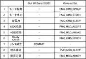
図25は、本発明の一実施形態に係る中継器43の動作を説明するためのフローチャートである。同図は、省電力モードへの移行要求の一つであるモータ停止コマンド“PMG_CMD_STDBY”によりスリープ状態の省電力モードにあるディスクデバイス41に対して、コントローラユニット42から書き込み要求コマンドが送出され、これによって、中継器43が当該ディスクデバイス41を通常モードに移行させるための処理を説明しており、上述した図14に対応している。モータ停止コマンド“PMG_CMD_STDBY”は、ディスクデバイス41のインターフェースラインをアクティブのままにする。 FIG. 25 is a flowchart for explaining the operation of the
ホスト装置2から書き込み要求コマンドがストレージ装置4に送出されると、コントローラユニット42は、キャッシュ機構423の作用により、当該コマンドをキャッシュメモリ上に一時的に格納するとともに、当該コマンドの書き込み対象データをディスクデバイス41に書き込むために、当該コマンドを中継器43に送出する。 When a write request command is sent from the
これを受けて、中継器43は、同図に示すように、コントローラユニット42から書き込み要求コマンドを受け取ると(STEP2501)、これをバッファメモリ436aにキャッシュ可能か否かをチェックする(STEP2502)。中継器43は、キャッシュ可能であると判断する場合(STEP2502の“No”)、書き込み要求コマンド及び書き込みデータをバッファメモリ436aに格納する(STEP2503)。なお、バッファメモリ436aが満杯であり、このためキャッシュ可能でない場合には、中継器43は、Queue Fullステータスをコントローラユニット42に送出する(STEP2512)。 In response to this, as shown in the figure, the
中継器43は、次に、コントローラユニット42に対して正常終了ステータスを送出する(STEP2504)。これにより、コントローラユニット42は、キャッシュメモリ上の当該書き込み要求コマンドに関する領域を開放する。 Next, the
続いて、中継器43は、書き込み対象となっているディスクデバイス41のスピンドルモータを起動させるために、当該ディスクデバイス41に対してモータ起動コマンド“PMG_CMD_SPNUP”を送出する(STEP2505)。当該コマンドを受け取ったディスクデバイス41は、コマンド受領応答メッセージ“PMG_MSG_ACCPT”を送出し、所定の起動処理を行う。 Subsequently, the
中継器43は、当該ディスクデバイス41からコマンド受領応答メッセージを受け取ると、当該ディスクデバイス41に対して起動報告要求コマンド“PMG_CMD_RPRDY”を送出し(STEP2506)、起動が完了したか否かを判断する(STEP2507)。ディスクデバイス41は、起動報告要求コマンドに応答して、コマンド受領応答メッセージ“PMG_MSG_ACCPT”を送出した後、起動報告応答メッセージ“PMG_MSG_AWAKE”を送出する。中継器43は、ディスクデバイス41から起動報告応答メッセージを受け取るか(STEP2507の“Yes”)、または一定時間が経過した時点で、次の処理に進む(STEP2508の“Yes”)。また、中継器43は、インターフェースコネクタのReadyLEDピンを監視することにより、ディスクデバイス41のREADY状態を検出するようにしてもよい。 Upon receiving the command receipt response message from the
起動完了メッセージを受け取った場合、または一定時間が経過した場合、中継器は、ディスクデバイス41に対して書き込み要求コマンドを送出する(STEP2509)。この書き込み要求コマンドは、SASまたはSATAのいずれかであるディスクデバイス41に依存するコマンドである。これを受けて、ディスクデバイス41は、書き込み処理を行い、書き込み処理が正常に終了した場合には、書き込み完了ステータスを中継器43に送出する。 When the activation completion message is received or when a certain time has elapsed, the repeater sends a write request command to the disk device 41 (STEP 2509). This write request command is a command depending on the
中継器43が書き込み完了ステータスを受け取った場合には(STEP2510の“Yes”)、書き込み要求コマンドに対する一連の処理が正常に終了することを意味するが、一定時間内に書き込み完了ステータスを受け取ることができなかった場合には(STEP2510の“No”)、中継器43は、次回のコマンド送出の機会に、当該ディスクデバイス41からのチェックコンディションステータスを示すメッセージを送出して(STEP2511)、処理を終了する。 When the
上述した例は、スタンバイ状態の省電力モードから通常モードへの移行処理であり、インターフェースラインはアクティブのままである。スリープ状態の省電力モードから通常モードへの移行処理の場合には、インターフェースラインは、インアクティブになっているため、OOB信号(COMINIT)を利用する。当該OOBは、本来、リンクの確立に使用されている。本実施形態では、当該OOBを受け取った時点でモータの起動を開始するように使用している。これにより、モータの起動に必要な時間を短縮することができるようになる。具体的には、STEP2505におけるモータ起動コマンド“PMG_CMD_SPNUP”に代えて、OOB信号(COMINIT)を送信すればよい。この場合、ディスクデバイス41は、これを受けて、OOBによるリンクの確立処理を行うとともに、起動処理を行う。 The above-described example is a transition process from the power saving mode in the standby state to the normal mode, and the interface line remains active. In the transition process from the power saving mode in the sleep state to the normal mode, the interface line is inactive, and thus an OOB signal (COMINIT) is used. The OOB is originally used for link establishment. In the present embodiment, the motor is started so as to start when the OOB is received. As a result, the time required for starting the motor can be shortened. Specifically, an OOB signal (COMINIT) may be transmitted instead of the motor start command “PMG_CMD_SPNUP” in
以上のように、本実施形態によれば、中継器43は、より上位のプロトコルスタック層に位置するSAS/SATAプロトコル層でのコマンドを解析するためのメカニズムを必要とすることがなく、部分的なソフトウェアの追加・変更により容易に対応することができ、システム回路の規模を小さくすることができる。また、SASプロトコルにおいても、データリンク層レベルでの省電力制御が可能になる。 As described above, according to the present embodiment, the
さらに、SASプロトコルとSATAプロトコルとでは、データフォーマットが異なるため(すなわち、SASはビックエンディアン方式を採用し、SATAはリトルエンディアン方式を採用している。)、本来、両者のプラットフォームを共通化することは困難であったが、このようなデータフォーマットを採用することにより、プラットフォームの共通化を図ることができるようになる。 Furthermore, since the data format is different between the SAS protocol and the SATA protocol (that is, the SAS adopts the big endian system and the SATA uses the little endian system), both platforms should be made common. However, adopting such a data format makes it possible to share a common platform.
次に、上述したパワーマネージメント・オーダード・セットに対応したディスクデバイス41(パワーマネージメント・オーダード・セットによる省電力制御方式)と、これに対応していないディスクデバイス41(例えば、SAS/SATAコマンドによる省電力制御方式)とが混在するストレージシステム環境について説明する。このような混在型のストレージシステム環境においては、両方式に対応する中継器43を提供することにより実現される。 Next, the
具体的には、中継器43は、パワーマネージメント・オーダード・セットによるプリミティブな省電力制御方式に対応しているか否かを判断し、当該方式に対応していないと判断する場合には、SAS/SATAコマンドによる省電力制御方式を選択する。 Specifically, the
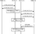
図26(a)及び(b)は、本発明の一実施形態に係るストレージ装置4における省電力方式の識別処理の一例を説明しており、具体的には、同図(a)は、パワーマネージメント・オーダード・セットに対応したSASディスクデバイス41aに対する省電力制御であり、また、同図(b)は、パワーマネージメント・オーダード・セットに対応していないSASディスクデバイス41aに対する省電力制御である。 FIGS. 26A and 26B illustrate an example of the power saving method identification process in the
すなわち、同図(a)及び(b)に示すように、中継器43は、最初に、ディスクデバイス41に対して発信用バージョン調停コマンド“PMG_VER_REQID”を送出し、所定の時間が経過するまで、応答メッセージの到着を待つ(同図(a)及び(b)の(1))。所定時間内に応答用バージョン調停メッセージ“PMG_VER_ACKID”を受け取った場合(同図(a)の(2))、相手側のディスクデバイス41は、パワーマネージメント・オーダード・セットによる省電力制御方式に対応しているとみなして、例えば、モータ停止コマンドを送出する(同図(a)の(3))。これに応答して、ディスクデバイス41は、コマンド受領応答メッセージ“PMG_MSG_ACCPT”を送出した後(同図(b)の(4))、省電力モードに移行する。 That is, as shown in FIGS. 4A and 4B, the
パワーマネージメント・オーダード・セットに対応していないディスクデバイス41は、パワーマネージメント・オーダード・セットを解釈することができないため、当該コマンドを破棄または無視し、応答がないことになる。したがって、所定時間内に何の応答もない場合には(同図(b)の(2))、パワーマネージメント・オーダード・セットに代えて、モータ停止コマンド“Unit STOP”を送出する(同図(b)の(3))。これに応答して、ディスクデバイス41は、正常終了ステータスを送出した後(同図(a)の(4))、省電力モードに移行する。 Since the
また、図27(a)及び(b)は、本発明の一実施形態に係るストレージ装置4における省電力制御方式の識別処理の一例を説明している。具体的には、同図(a)は、パワーマネージメント・オーダード・セットに対応したSATAディスクデバイス41bに対する省電力制御であって、同図(b)は、パワーマネージメント・オーダード・セットに対応していないSATAディスクデバイス41bに対する省電力制御である。本例では、スピンドルモータを停止するとともにインターフェースラインをインアクティブにする省電力モードを選択している。 FIGS. 27A and 27B illustrate an example of identification processing of the power saving control method in the
すなわち、同図(a)及び(b)に示すように、中継器43は、最初に、ディスクデバイス41に対して発信用バージョン調停コマンド“PMG_VER_REQID”を送出し、所定の時間が経過するまで、応答メッセージの到着を待つ(同図(a)及び(b)の(1))。所定時間内に応答用バージョン調停メッセージ“PMG_VER_ACKID”を受け取った場合(同図(a)の(2))、相手側のディスクデバイス41は、パワーマネージメント・オーダード・セットによる省電力制御方式に対応しているとみなして、例えば、モータ停止コマンドを送出する(同図(a)の(3))。本例では、モータ停止コマンド“PMG_CMD_SLEEP”が送出されている。これに応答して、ディスクデバイス41は、コマンド受領応答メッセージ“PMG_MSG_ACCPT”を送出した後(同図(a)の(4))、省電力モードに移行する。 That is, as shown in FIGS. 4A and 4B, the
これに対して、所定時間内に何の応答もない場合には(同図(b)の(2))、モータ停止コマンド“SLEEP”を送出する(同図(b)の(3))。これに応答して、ディスクデバイス41は、正常終了ステータスを送出した後(同図(a)の(4))、省電力モードに移行する。 On the other hand, when there is no response within a predetermined time ((2) in FIG. 2B), a motor stop command “SLEEP” is transmitted ((3) in FIG. 2B). In response to this, the
なお、インターフェースラインがインアクティブにならないと判断する場合、中継器43は、既定のプリミティブコマンドを発行してもよい。
[第3の実施形態]
次に、障害等によるシステムダウンの防止を目的として、複数のディスクデバイス41をディスクアレイ状に冗長化構成したストレージ装置4における省電力制御について説明する。このような冗長化構成に対して、例えば、RAID技術が知られている。If it is determined that the interface line is not inactive, the
[Third Embodiment]
Next, power saving control in the
冗長化構成に対応したディスクデバイス41は、データのパスを二重化するために、典型的には、一対のポート(デュアルポート)を備える。したがって、ディスクデバイス41が、一方の中継器43からデュアルポートの一方に省電力モードへの移行要求を受け付けた場合であっても、ディスクデバイス41は、インターフェースラインをインアクティブにするだけであり、デュアルポートの他方にも省電力モードへの移行要求を受け付けない限り、スピンドルモータを停止させることができない。このため、ディスクデバイス41は、単に、部分的な省電力に寄与するだけであり、省電力を効率的に行うことができない。
また、省電力モード移行条件は、中継器43ごとに設定されるため、中継器43は、その配下に接続されたディスクデバイス41についてのみ、省電力制御を行っている。したがって、各中継器43において最小駆動台数が3台に設定されている場合、1台の中継器43から見れば、その条件を満たすことになるが、冗長化構成されたシステム全体から見れば、最大でその2倍の台数のディスクデバイス41が動作している場合がある。The
Further, since the power saving mode transition condition is set for each
そこで、本実施形態においては、ディスクデバイス41が、一方の中継器43からデュアルポートの一方に省電力モードへの移行要求を受け付けた場合、他方の中継器43に対して、省電力モードへの移行要求を発行するように、メッセージを送出する。省電力モードへの移行要求を受け取った他方の中継器43は、省電力モード移行条件に合致するか否かを判断して、合致する場合には、当該ディスクデバイス41を省電力モードに移行させる。これによって、システム全体として動作しているディスクデバイス41に対して効率的に省電力を行うことができるようになる。 Therefore, in the present embodiment, when the
図28は、本発明の一実施形態に係るストレージ装置4の構成を示す図である。同図に示すように、コントローラユニット42は、デュアル構成となっており、データコントローラ427を介して相互に接続されている。コントローラユニット42はまた、共用メモリ428を備える。各コントローラユニット42は、2つのディスクインターフェース425を備える。当該各ディスクインターフェース425は、中継器43a1及び43b1のそれぞれと接続され、当該各中継器43a1及び43b1は、さらに他の中継器43a2及び43b2にそれぞれ接続されている。 FIG. 28 is a diagram showing a configuration of the
中継器43は、前述したように、省電力制御部を備え、配下に接続されるディスクデバイス41に対する省電力制御を行うことができるように構成されている。ディスクデバイス41は、デュアルポートを備え、一対の中継器43に接続される。ただし、本実施形態で採用されるディスクデバイス41のうちデュアルポートを有するものは、SASディスクデバイス41aであり、SATAディスクデバイス41bは、一般に、シングルポートを有するのみである。このためSATAディスクデバイス41bは、後述するように、ポートアダプタボードを実装した1台のSATAディスクデバイス41bによって、またはポートアダプタ上にポートマルチプライヤを実装した2台のSATAディスクデバイス41bによって、見かけ上、デュアルポートを有するディスクデバイスとしている。 As described above, the
冗長化構成のディスクデバイス41に対する効率的な省電力制御を実現するため、本実施形態では、図29に示すように、2つのパワーマネージメント・オーダード・セットを新たに定義する。新たなパワーマネージメント・オーダード・セットは、他系確認メッセージ“PMG_MSG_SLEEP”及び拒否応答メッセージ“PMG_MSG_ADNEY”である。 In order to realize efficient power saving control for the
図30は、本発明の一実施形態に係るストレージ装置4における省電力モード移行要求時の処理の流れを説明している。 FIG. 30 explains the flow of processing at the time of request for shifting to the power saving mode in the
同図に示すように、一方の中継器43aは、配下のディスクデバイス41に対して省電力モード移行要求コマンド(例えば、PMG_CMD_SLEEP)を送出する(図中(1))。ディスクデバイス41は、当該コマンドを一方のポート(例えば、ポートA)を介して受け取ると、コマンド受領応答メッセージを送出し(図中(2))、インターフェースラインをインアクティブにする。ディスクデバイス41はまた、他方のポート(例えば、ポートB)を介して他系確認メッセージ“PMG_MSG_SLEEP”を中継器43bに送出する(図中(3))。 As shown in the figure, one repeater 43a sends a power saving mode shift request command (for example, PMG_CMD_SLEEP) to the subordinate disk device 41 ((1) in the figure). When the
中継器43bは、当該他系確認メッセージを受け取ると、当該ディスクデバイス41が省電力モード移行条件に合致しているか否かを判断し、合致していると判断する場合には、省電力モード移行要求コマンドを送出する(図中(4))。 Upon receiving the other system confirmation message, the repeater 43b determines whether or not the
ディスクデバイス41は、ポートBから省電力モード移行要求コマンドを受け取ると、コマンド受領応答メッセージを送り返す(図中(5))。この場合、ディスクデバイス41は、双方のポートからインターフェースラインをインアクティブするためのコマンドを受け取ったため、スピンドルモータを停止させる。 When the
一方、中継器43bは、当該他系確認メッセージを受領し、当該ディスクデバイス41が省電力モード移行条件に合致していないと判断する場合には、拒否応答メッセージを送出する(図中(4)’)。この場合、ディスクデバイス41は、スピンドルモータを停止させることなく、ポートAに対するインターフェースラインのみをインアクティブにする部分的な省電力モードの状態を継続させる。 On the other hand, when the repeater 43b receives the other system confirmation message and determines that the
図31は、本発明の一実施形態に係るストレージ装置4における通常モード移行要求時の処理の流れを説明している。 FIG. 31 explains the flow of processing when a normal mode shift request is issued in the
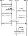
例えば、コントローラユニット42からI/Oアクセス要求を受け取った一方の中継器43aは、同図に示すように、まず、OOB信号である“COMINIT”を送出する(図中(1))。OOB信号は、デバイス間のプリミティブなハンドシェイク信号である。ディスクデバイス41は、“COMINIT”信号を受け取ると、“COMSAS/COMWAKE”信号で応答し(図中(2))、インターフェースラインをアクティブにする。ディスクデバイス41はまた、他方の中継器43bに対して“COMINIT”信号を送信する(図中(3))。 For example, one repeater 43a that has received an I / O access request from the
“COMINIT”信号を受信した中継器43bは、“COMSAS/COMWAKE”を送信する(図中(4))。なお、I/Oアクセス要求を受け取っていない中継器43bは、スピンドルモータを起動する必要がないため、“COMSAS/COMWAKE”信号により応答しない(図中(4)’)。 The repeater 43b that has received the “COMINIT” signal transmits “COMSAS / COMWAKE” ((4) in the figure). Note that the repeater 43b that has not received the I / O access request does not need to start the spindle motor, and therefore does not respond with the "COMSAS / COMWAKE" signal ((4) 'in the figure).
また、中継器43aは、ディスクデバイス41の対応するポートAに対して起動通知要求コマンド“PMG_CMD_RPRDY”を送出し(図中(5))、ディスクデバイス41は、これに応答してコマンド受領通知メッセージ“PMG_MSG_ACCPT”を送出する(図中(6))。同様に、他方の中継器43aは、ディスクデバイス41の対応するポートBに対して起動通知要求コマンド“PMG_CMD_RPRDY”を送出し(図中(7))、ディスクデバイス41は、これに応答してコマンド受領通知メッセージ“PMG_MSG_ACCPT”を送出する(図中(8))。なお、これらのメッセージ及びコマンドのやり取りは、同一タイミングである必要はない。ディスクデバイス41は、スピンドルモータを起動して、通常モードに移行すると、双方のポートA及びBから起動報告応答メッセージ“PMG_MSG_AWAKE”を送出する(図中(9))。 Further, the repeater 43a sends an activation notification request command “PMG_CMD_RPRDY” to the corresponding port A of the disk device 41 ((5) in the figure), and the
以上のように、本実施形態によれば、ディスクデバイス41が不要な状態遷移待ちになることを極力排除することができるようになる。また、中継器43は、他系の中継器43の存在を認識することができる。したがって、他系確認メッセージ“PMG_MSG_SLEEP”を受け取った中継器43は、送り元の中継器43の省電力に追随するように動作することで、最小駆動台数の同期制御をできるようになる。 As described above, according to the present embodiment, it is possible to eliminate as much as possible that the
本実施形態において、シングルポートであるSATAディスクデバイス41bを採用する場合、例えば、図32(a)に示すように、ディスクデバイス本体筐体内部にポートスイッチアダプタボード321a及びディスクデバイス41bを搭載する。ポートスイッチアダプタ321aは、デュアルポート(ポートA及びB)を備え、これらのポートを切り替えるスイッチング機能を内蔵する。これによって、当該1台のSATAディスクデバイス41bを、見かけ上、デュアルポートとして機能させることができる。または、2台のSATAディスクデバイスを採用した場合には、例えば、図32(b)に示すように、ポートマルチプライヤ(PM)コントローラ321bをポートアダプタ上に搭載すればよい。これにより、当該2台のSATAディスクデバイス41bを、見かけ上、デュアルポートとして機能させることができる。これらポートスイッチアダプタボード321aまたはポートマルチプライヤ(PM)コントローラ321bは、上述した省電力制御のためのパワーマネージメント・オーダード・セットに対応した機能を実装する。 In this embodiment, when the
図33は、本発明の一実施形態に係るSATAディスクデバイス41bを説明する図である。同図に示すように、ポートマルチプライヤコントローラ321bは、SASコネクタ322とSATAコネクタ323との間に配置され、それによって、2台のSATAディスクデバイス41bを、見かけ上、2つのポートを備えたディスクデバイス41として機能させることができる。2台のSATAディスクデバイス41bは、例えば、2.5インチディスクドライブを採用することができる。 FIG. 33 is a diagram for explaining a
中継器43は、ポートマルチプライヤ321bの自系ポートを“0”、他系ポートを“1”として識別することで、冗長化構成を実現できる。2系統のパスは、各SATAディスクデバイス41bに直接的に割り当てられる。中継器43は、パスのスイッチ作用により、他系のSATAディスクデバイス41bに対してアクセスすることができる。 The
また、ポート切り替え機構は、一方のポートから入力されたデータを他方のポートに対して複製するように構成されてもよい。この場合、2台のSATAディスクデバイス41bは、ミラーリングディスクとして運用され、読み出しアクセス要求に対しては、例えば、応答速度の速い方の出力が選択される。 The port switching mechanism may be configured to replicate data input from one port to the other port. In this case, the two
さらに、ポート切り替え機構は、外部からの信号によりポートスイッチを切り替えるように構成されてもよい。または、コントローラユニット42によるデータの冗長化により対応してもよい。 Further, the port switching mechanism may be configured to switch the port switch by an external signal. Alternatively, the
また、ポートマルチプライヤ321bは、時間差電源供給スイッチを備える。時間差電源供給スイッチは、2台のSATAディスクデバイス41bに対して所定の時間差をあけて電源を供給する。 The
本実施形態におけるSATAディスクデバイス41bは、既述した省電力制御に加え、ポートスイッチアダプタボード321aまたはポートマルチプライヤ321bの当該スイッチをON/OFFすることにより省電力制御を行ってもよい。したがって、パワーマネージメント・オーダード・セットを解釈できないSATAディスクデバイス41bに対しても、ポートスイッチアダプタボード321aまたはポートマルチプライヤ321bを介して省電力制御を行うことができるようになる。
[第4の実施形態]
本実施形態におけるストレージ装置4は、省電力制御機能を有しない従来型の中継器43’を統括するアドバンスド中継器43Aを備える。In addition to the power saving control described above, the
[Fourth Embodiment]
The
図34は、本発明の一実施形態に係るストレージ装置4の構成を示す図である。なお、本実施形態においても、ディスクデバイス41は、冗長化構成となっている。同図に示すように、中継器43Aは、コントローラユニット42とディスクデバイス41との間に接続される。中継器43Aは、複数の中継器43’を並列的に接続している。中継器43は、省電力モード移行条件に加え、省電力運用ポリシーの設定をすることができる。省電力運用ポリシーは、例えば、使用環境やカレンダ機能と連動させた省電力モード移行条件の切り替えルールを含む。例えば、運用停止時点に省電力モードに変更し、運用再開時点に通常モードに変更するといった運用ポリシーである。 FIG. 34 is a diagram showing a configuration of the
図35は、本発明の一実施形態に係る中継器43の構成を示す図である。同図に示すように、中継器43Aは、冗長化構成に対応するように、2つのシステム回路構成となっている。上述したように、中継器43Aは、省電力制御のためのパワーマネージメント・オーダード・セットに対応した機能を実装している。アドオンメモリ437は、システムの拡張性を考慮して設けられたメモリである。アドオンメモリ437は、図36に示すように、中継器の構成、省電力運用ポリシー、及び省電力モード選択に関する情報等のプロファイルを記憶する。
中継器の構成情報は、配下に接続される中継器43’の構成及びモード設定等を含む。モード設定は、例えば、中継器単位で設定するのか、ポート単位で設定するのか、あるいはディスクデバイス種別単位で設定するのかといったモードを示す。省電力運用ポリシー情報は、例えば、休日や特定日、時間帯単位、I/Oトラフィック量等に基づいた設定の切り替えポリシーを含む。省電力モード選択は、省電力を抑止するモードや優先するモードといったさまざまな省電力モードを含む。システム管理者は、これらのプロファイルをアドバンスド中継器43Aに対して直接的に設定するか、またはコントローラ42から設定することができる。したがって、このようなプロファイルを適宜に設定することにより、ストレージシステムの使用目的を容易に切り替え、また、カレンダや業務形態にしたがって省電力モードを切り替えることができるため、省電力モードと通常モード間の移行待ち時間を短縮でき、再起動時間の延長等も可能になり、よって、システムの効率的な運用による省電力効果を期待できる。FIG. 35 is a diagram showing a configuration of the
The configuration information of the repeater includes the configuration and mode setting of the
図35に戻り、外部メモリインターフェース438は、脱着可能な、例えばカード型の不揮発性メモリを接続するためのインターフェースである。中継器43は、外部メモリインターフェース438に接続された不揮発性メモリをバッファメモリとして利用することができる。これにより、利用状況に応じて、メモリ容量を柔軟に選択することができる。 Returning to FIG. 35, the
拡張ポート434’は、コントローラユニット42及び他の機器(中継器43’やディスクデバイス41等)を接続するためのものである。 The expansion port 434 'is for connecting the
中継器43Aは、各ディスクデバイス41のSMART情報を収集する機能も含む。中継器43は、収集したSMART情報に基づいて、次回の電源起動のタイミングを予測し、不要な確認応答コマンドの発行を抑制する。また、中継器43は、当該予測に従って、Queue Fullステータスコマンドを発行しておくことで、コントローラユニット42のリトライを促して、コントローラユニット42のタイムアウトを防止する。 The
本実施形態では、アドバンスド中継器43Aの配下には、従来型の中継器43’が接続されていたが、これまでの実施形態で述べてきたような中継43を配置してもよい。この場合、アドバンスド中継器43Aが、省電力運用ポリシー情報にしたがって、下位の各中継器43に設定を行う。
また、本実施形態の中継器43Aは、ディスクデバイス41が起動を行っている間に、バッファメモリ436内にキャッシュされたデータの読み出し要求をコントローラユニット42から受け付けた場合、当該キャッシュされたデータをコントローラユニット42に送出するように構成されてもよい。このようなキャッシュ作用は、既述したようなメタデータを中継器43が保持することにより、実現される。なお、所望のデータがキャッシュされていない場合には、読み出し要求は、対象となるディスクデバイス41が起動するまで、バッファメモリ436に保持される。In the present embodiment, the
When the
さらに、中継器43の拡張ポート434’は、ポートごとにI/Oアクセス量(I/Oトラフィック量)を監視するように構成してもよい。中継器43Aは、当該I/Oアクセス量に基づいて、ポートごとの稼働状況に関するレポートを管理端末5に出力する。これによって、システム管理者は、省電力運用ポリシーを設定する際の参考に資することができるようになる。 Further, the
[実施形態の作用効果]
上記実施形態に係る記憶システムによれば、すでに述べたようなまたは以下に述べるような効果ないしは利点を奏する。[Effects of Embodiment]
The storage system according to the above embodiment has the effects or advantages as described above or described below.
上記実施形態によれば、コントローラユニットとディスクデバイスとの間に位置する中継器が、ディスクデバイスに対する電力制御を行うので、コントローラユニットはI/Oアクセス要求に伴う本来の処理に専念することができ、コントローラユニットと中継器とは必要最小限の通信を行うだけで足り、したがって、コントローラユニットの処理パフォーマンスを低下させることはない。また、コントローラユニットは電力制御に関わる処理を行う必要がないため、当該処理に必要なメモリを別に搭載する必要がなく、中継器に当該処理を行わせることで、相対的にシステムコストを低く抑えることができるようになる。 According to the above embodiment, the repeater located between the controller unit and the disk device performs power control on the disk device, so that the controller unit can concentrate on the original processing accompanying the I / O access request. The controller unit and the repeater need only perform the minimum communication, and therefore, the processing performance of the controller unit is not deteriorated. In addition, since the controller unit does not need to perform processing related to power control, it is not necessary to separately install a memory necessary for the processing, and the system cost can be kept relatively low by causing the repeater to perform the processing. Will be able to.
また、中継器は、所定の省電力モード移行条件に従って、所定のディスクデバイスを省電力モードに移行させるので、効率的な電力制御を行うことができる。特に、上記実施形態では、一定時間内にI/Oアクセス要求があっても、所定量のI/Oアクセス要求がないディスクデバイスを省電力モードに移行するので、さらなる省電力化を図ることができるようになる。さらに、最小駆動台数を定めてディスクデバイスを運用し、応答性等のパフォーマンスを著しく低下させることがないように考慮されている。 Further, the repeater shifts a predetermined disk device to the power saving mode in accordance with a predetermined power saving mode shift condition, so that efficient power control can be performed. In particular, in the above embodiment, even if there is an I / O access request within a certain period of time, a disk device that does not have a predetermined amount of I / O access request is shifted to the power saving mode. become able to. Furthermore, it is considered that a disk device is operated by setting a minimum drive number so that performance such as responsiveness is not significantly lowered.
また、省電力モードにあるディスクデバイスが通常モードに移行する際に、ディスクデバイスのスピンドルモータが定常状態になるまでに時間を要し、書き込み対象データに対する遅延処理に伴うデータ損失のおそれに対し、遅延書き込みデータ保護メカニズムにより、データの損失を防止している。 In addition, when a disk device in the power saving mode shifts to the normal mode, it takes time until the spindle motor of the disk device becomes a steady state. Data loss is prevented by the delayed write data protection mechanism.
さらに、上記実施形態によれば、中継器とディスクデバイスとは、プリミティブな信号により通信しているので、上位のプロトコルスタック層におけるコマンドを解析するためのメカニズムを必要とすることがなく、したがって、部分的なソフトウェアの追加・変更により容易に実装することができ、システム回路の規模を小さくすることができる。 Furthermore, according to the above embodiment, the repeater and the disk device communicate with each other by a primitive signal, so that a mechanism for analyzing a command in the upper protocol stack layer is not required, and therefore It can be easily implemented by adding or changing partial software, and the scale of the system circuit can be reduced.
また、上記実施形態によれば、中継器は、冗長化構成のディスクデバイスに対応させることができるため、柔軟なシステムを構成することができるようになる。 Further, according to the above embodiment, the repeater can correspond to the disk device having a redundant configuration, so that a flexible system can be configured.
本発明は、コンピュータシステム上で処理されるデータを記憶するストレージ装置に幅広く適用することができる。特に、本発明は、データの消失を防止するため、データのバックアップおよび復元・復旧のために用いられるストレージ装置に適用することができる。 The present invention can be widely applied to storage apparatuses that store data processed on a computer system. In particular, the present invention can be applied to a storage device used for data backup, restoration, and recovery in order to prevent data loss.
1…記憶システム
2…ホスト装置
21…CPU
22…ローカルメモリ
23…インターフェース部
24…ローカル入出力装置
25…内部バス
3…ネットワークシステム
4…ストレージ装置
41…ディスクデバイス
42…コントローラユニット
421…CPU
422…ローカルメモリ
423…キャッシュ機構
424…チャネルアダプタ
425…ディスクインターフェース
426…外部インターフェース
5…管理端末
43…中継器1 ...
22 ...
422 ...
Claims (20)
Translated fromJapaneseホスト装置に接続され、当該ホスト装置からのアクセス要求に応じた処理を行う複数のコントローラユニットと、
複数の記憶デバイスと、
複数のポートを有し、当該複数のポートを介して前記複数のコントローラユニットと前記複数の記憶デバイスとに接続され、前記複数のコントローラのうちの少なくとも1つのコントローラから受領するアクセス要求に応じて、当該コントローラと前記複数の記憶デバイスのうちの少なくとも1つの記憶デバイスとのデータ転送を中継する中継器と
を備え、
前記中継器は、
前記複数のコントローラのいずれかのコントローラから設定された省電力制御のためのパラメータに基づいて、前記複数のポートのうち第1の記憶デバイスに対応する第1のポートを介して前記第1の記憶デバイスの動作状態を省電力状態に移行するコマンドを前記第1の記憶デバイスに発行し、
前記コマンドを受領した前記第1の記憶デバイスからの応答に基づいて、前記第1の記憶デバイスに対応する第1のポートのインターフェースを省電力状態に移行するように制御する
ことを特徴とするストレージ装置。A storage device for storing data,
Aplurality of controller unitsconnected to the host device and performing processing in response to an access request from the host device;
Multiple storage devices;
Have a plurality ofports, connected to said plurality of storage devices and said plurality of controller unit via the plurality of ports in response to access requests received from the at least one controller of the plurality of controllers, A relay for relayingdata transfer between the controller and at least one storage device of the plurality of storage devices ,
The repeater is
Based on the parameter for power saving control set from any one of the plurality of controllers, the first storage via the first port corresponding to the first storage device among the plurality of ports. Issuing a command to shift the operating state of the device to the power saving state to the first storage device;
Storage thatcontrols the interface of the first port corresponding to the first storage device to shift to a power saving state based on a response from the first storage device that has received the command apparatus.
前記中継器は、The repeater is
SASプロトコルによる通信を行うSASエクスパンダであるIt is a SAS expander that performs communications using the SAS protocol.
ことを特徴とするストレージ装置。A storage device.
前記コントローラは、The controller is
第1のプロトコルに従って、前記中継器にパラメータを設定し、According to a first protocol, setting parameters in the repeater;
前記中継器は、The repeater is
前記第1のプロトコルとは異なる第2のプロトコルに従い、前記第1の記憶デバイスの動作状態を省電力状態に移行するコマンドを発行するIssuing a command to shift the operating state of the first storage device to a power saving state according to a second protocol different from the first protocol
ことを特徴とするストレージ装置。A storage device.
前記第1のプロトコルは、SMPプロトコルであるThe first protocol is an SMP protocol
ことを特徴とするストレージ装置。A storage device.
前記複数のディスクデバイスは、
第1のディスクデバイス群と、前記第1のディスクデバイス群と異なる性能を有する第2のディスクデバイス群とからなる
ことを特徴とするストレージ装置。The storage device according to claim 1,
The plurality of disk devices are:
A storage apparatus, comprising: a first disk device group; and a second disk device group having a performance different from that of the first disk device group.
前記第1のディスクデバイス群は、
SAS規格のハードディスクデバイスであり、
前記第2のディスクデバイス群は、
SATA規格のハードディスクデバイスである
ことを特徴とするストレージ装置。The storage apparatus according to claim 5,
The first disk device group is:
A SAS standard hard disk device,
The second disk device group is:
A storage device characterized by being a SATA hard disk device.
前記中継器は、
所定のパワーマネージメントに関するプロファイルを備え、
前記所定のパワーマネージメントに関するプロファイルに定義される省電力モード移行条件に従って、前記電力制御により前記ディスクデバイスを省電力モードに移行させる
ことを特徴とするストレージ装置。The storage device according to claim 1,
The repeater is
It has a profile for predetermined power management,
A storage apparatus, wherein the disk device is shifted to a power saving mode by the power control according to a power saving mode shift condition defined in a profile relating to the predetermined power management.
前記中継器は、
前記複数のポートのそれぞれに対する状態パラメータを含むポート管理テーブルを備え、
前記ポート管理テーブルに従って、前記複数のポートのそれぞれに接続されたディスクデバイスに対する前記電力制御を行う
ことを特徴とするストレージ装置。The storage device according to claim 7,
The repeater is
A port management table including a status parameter for each of the plurality of ports;
The storage apparatus according to claim 1, wherein the power control is performed on a disk device connected to each of the plurality of ports according to the port management table.
前記中継器は、
前記省電力モード移行条件に示された所定の時間以上前記アクセス要求がないポートを、前記ポート管理テーブルを参照して、選択し、当該選択されたポートに接続されたディスクデバイスを省電力モードに移行させる
ことを特徴とするストレージ装置。The storage apparatus according to claim 8, wherein
The repeater is
A port that has not been accessed for the predetermined time or more indicated in the power saving mode transition condition is selected with reference to the port management table, and the disk device connected to the selected port is set to the power saving mode. A storage device that is migrated.
前記中継器は、
前記省電力モード移行条件に示された所定のアクセス要求量以下のポートを、前記ポート管理テーブルを参照して、選択し、当該選択されたポートに接続されたディスクデバイスを省電力モードに移行させる
ことを特徴とするストレージ装置。The storage apparatus according to claim 8, wherein
The repeater is
A port having a predetermined access request amount or less indicated in the power saving mode transition condition is selected with reference to the port management table, and a disk device connected to the selected port is shifted to the power saving mode. A storage device.
前記中継器は、
前記電力制御により省電力モードにあるディスクデバイスの台数が前記省電力モード移行条件に示された最小駆動台数に等しい場合に、前記省電力モード移行条件に示された再起動時間に達しているポートを、前記ポート管理テーブルを参照して、選択し、当該再起動時間に達しているポートに接続されたディスクデバイスを起動する
ことを特徴とするストレージ装置。The storage apparatus according to claim 8, wherein
The repeater is
The port that has reached the restart time indicated in the power saving mode transition condition when the number of disk devices in the power saving mode by the power control is equal to the minimum drive number indicated in the power saving mode transition condition The storage apparatus is characterized by selecting a disk device with reference to the port management table and starting a disk device connected to the port that has reached the restart time.
前記中継器は、
通常モード移行条件に従い、前記電力制御により省電力モードにあるディスクデバイスを通常モードに移行させる
ことを特徴とするストレージ装置。The storage device according to claim 1,
The repeater is
A storage apparatus, wherein a disk device in a power saving mode is shifted to a normal mode by the power control according to a normal mode shift condition.
前記中継器は、
前記アクセス要求が前記省電力モードにあるディスクデバイスに対してあった場合に、当該ディスクデバイスを前記通常モードに移行させた後に、当該ディスクデバイスに対して前記アクセス要求を送出する
ことを特徴とするストレージ装置。The storage device according to claim 12, wherein
The repeater is
When the access request is for a disk device in the power saving mode, the access request is sent to the disk device after the disk device is shifted to the normal mode. Storage device.
前記コントローラは、
前記中継器が前記省電力モードにあるディスクデバイスを前記通常モードに移行させるまでの間、所定のタイムアウト間隔に従って、前記中継器とのセッションを維持するための処理を行う
ことを特徴とするストレージ装置。The storage device according to claim 13,
The controller is
The storage apparatus performs processing for maintaining a session with the repeater according to a predetermined timeout interval until the repeater shifts the disk device in the power saving mode to the normal mode. .
前記コントローラは、
キャッシュメモリを備え、
前記中継器によって前記省電力モードにあるディスクデバイスが前記通常モードに移行し、前記アクセス要求が当該ディスクデバイスに送出されるまでの間、前記アクセス要求を前記キャッシュメモリに保持する
ことを特徴とするストレージ装置。The storage device according to claim 13,
The controller is
With cache memory,
The access request is held in the cache memory until the disk device in the power saving mode shifts to the normal mode by the repeater and the access request is sent to the disk device. Storage device.
前記中継器は、
バッファメモリを備え、
前記省電力モードにあるディスクデバイスを前記通常モードに移行させ、前記アクセス要求を当該ディスクデバイスに送出するまでの間、前記アクセス要求を前記バッファメモリに保持する
ことを特徴とするストレージ装置。The storage device according to claim 13,
The repeater is
With buffer memory,
The storage apparatus, wherein the access request is held in the buffer memory until the disk device in the power saving mode is shifted to the normal mode and the access request is sent to the disk device.
前記中継器は、
前記省電力モードにあるディスクデバイスを前記通常モードに移行させ、前記アクセス要求を当該ディスクデバイスに送出するまでの間、前記アクセス要求を、前記通常モードにあるディスクデバイスに保持する
ことを特徴とするストレージ装置。The storage device according to claim 13,
The repeater is
The access request is held in the disk device in the normal mode until the disk device in the power saving mode is shifted to the normal mode and the access request is sent to the disk device. Storage device.
前記中継器は、
不揮発性の外部ストレージを備え、
前記省電力モードにあるディスクデバイスを前記通常モードに移行させ、前記アクセス要求を当該ディスクデバイスに送出するまでの間、前記アクセス要求を、前記外部ストレージに保持する
ことを特徴とするストレージ装置。The storage device according to claim 13,
The repeater is
With non-volatile external storage,
The storage apparatus is characterized in that the access request is held in the external storage until the disk device in the power saving mode is shifted to the normal mode and the access request is sent to the disk device.
前記中継器は、
プリミティブなパルス通信を定義するプロトコル層に属するパワーマネージメント・オーダード・セットを用いて、前記ディスクデバイスに対する前記電力制御を行う
ことを特徴とするストレージ装置。The storage device according to claim 1,
The repeater is
A storage apparatus, wherein the power control for the disk device is performed using a power management ordered set belonging to a protocol layer defining primitive pulse communication.
前記中継器は、
プリミティブなパルス通信を定義するプロトコル層に属するアウト・オブ・バンド信号を用いて、前記ディスクデバイスに対する前記電力制御を行う
ことを特徴とするストレージ装置。The storage device according to claim 1,
The repeater is
The storage apparatus, wherein the power control for the disk device is performed using an out-of-band signal belonging to a protocol layer defining primitive pulse communication.
Priority Applications (5)
| Application Number | Priority Date | Filing Date | Title |
|---|---|---|---|
| JP2006218292AJP4897387B2 (en) | 2006-08-10 | 2006-08-10 | Storage apparatus and data management method using the same |
| US11/580,105US7730235B2 (en) | 2006-08-10 | 2006-10-11 | Storage apparatus for controlling power saving modes of multiple disk devices of different specifications |
| EP07251064AEP1895396A3 (en) | 2006-08-10 | 2007-03-14 | A storage apparatus and a data management method employing the storage apparatus |
| US12/775,702US8131892B2 (en) | 2006-08-10 | 2010-05-07 | Storage apparatus and a data management method employing the storage apparatus |
| US13/149,569US8612644B2 (en) | 2006-08-10 | 2011-05-31 | Storage apparatus and a data management method employing the storage apparatus |
Applications Claiming Priority (1)
| Application Number | Priority Date | Filing Date | Title |
|---|---|---|---|
| JP2006218292AJP4897387B2 (en) | 2006-08-10 | 2006-08-10 | Storage apparatus and data management method using the same |
Publications (2)
| Publication Number | Publication Date |
|---|---|
| JP2008041050A JP2008041050A (en) | 2008-02-21 |
| JP4897387B2true JP4897387B2 (en) | 2012-03-14 |
Family
ID=38694887
Family Applications (1)
| Application Number | Title | Priority Date | Filing Date |
|---|---|---|---|
| JP2006218292AExpired - Fee RelatedJP4897387B2 (en) | 2006-08-10 | 2006-08-10 | Storage apparatus and data management method using the same |
Country Status (3)
| Country | Link |
|---|---|
| US (3) | US7730235B2 (en) |
| EP (1) | EP1895396A3 (en) |
| JP (1) | JP4897387B2 (en) |
Families Citing this family (77)
| Publication number | Priority date | Publication date | Assignee | Title |
|---|---|---|---|---|
| JP4325817B2 (en) | 1999-04-05 | 2009-09-02 | 株式会社日立製作所 | Disk array device |
| US8360942B2 (en)* | 2005-08-09 | 2013-01-29 | The University Of Toledo | Core muscle strengthening |
| US7613879B2 (en)* | 2007-01-24 | 2009-11-03 | Dell Products L.P. | Method, system and media for improved operation of a device in a foreign domain |
| US8910234B2 (en)* | 2007-08-21 | 2014-12-09 | Schneider Electric It Corporation | System and method for enforcing network device provisioning policy |
| US7809964B1 (en)* | 2007-09-28 | 2010-10-05 | Emc Corporation | Storage system assembly with distributed enclosure management |
| US8111610B2 (en)* | 2008-01-25 | 2012-02-07 | Emulex Design & Manufacturing Corporation | Flagging of port conditions in high speed networks |
| JP2009194675A (en)* | 2008-02-15 | 2009-08-27 | Fujitsu Ltd | Network configuration management program, network configuration management apparatus, and network configuration management method |
| US7904566B2 (en)* | 2008-03-14 | 2011-03-08 | Silicon Image, Inc. | Method, apparatus, and system for employing an enhanced port multiplier |
| US7979589B2 (en)* | 2008-03-14 | 2011-07-12 | Silicon Image, Inc. | Method, apparatus, and system for port multiplier enhancement |
| US7949789B2 (en)* | 2008-03-25 | 2011-05-24 | International Business Machines Corporation | Distance extender for serial attached SCSI and serial ATA |
| US8019895B2 (en)* | 2008-03-25 | 2011-09-13 | International Business Machines Corporation | Serial attached SCSI and serial ATA wide port tunnelling through a fibre channel connection |
| US8984303B2 (en)* | 2008-04-01 | 2015-03-17 | Netapp, Inc. | System for automating storage device swaps and/or replacements |
| JP4568770B2 (en)* | 2008-04-22 | 2010-10-27 | 株式会社日立製作所 | Power control method for computer system, computer system, and management computer |
| JP4819088B2 (en) | 2008-04-25 | 2011-11-16 | 富士通株式会社 | Storage device and method for starting the storage device |
| JP2009266178A (en)* | 2008-04-30 | 2009-11-12 | Fujitsu Ltd | Relay device and relay system |
| JP4551947B2 (en)* | 2008-05-23 | 2010-09-29 | 株式会社日立製作所 | Device that manages the electronic devices that make up the storage system |
| JP5146123B2 (en)* | 2008-06-10 | 2013-02-20 | 富士通株式会社 | Management device, management method, management program, and electronic device |
| JP2010009494A (en) | 2008-06-30 | 2010-01-14 | Toshiba Corp | Information processor, control method, and program |
| JP2010015518A (en) | 2008-07-07 | 2010-01-21 | Hitachi Ltd | Storage system |
| JP4838832B2 (en)* | 2008-08-29 | 2011-12-14 | 富士通株式会社 | Storage system control method, storage system, and storage apparatus |
| US8155766B2 (en)* | 2008-11-03 | 2012-04-10 | Hitachi, Ltd. | Methods and apparatus to provision power-saving storage system |
| JP4893731B2 (en)* | 2008-12-25 | 2012-03-07 | 富士通株式会社 | Communication control device |
| US20100199036A1 (en)* | 2009-02-02 | 2010-08-05 | Atrato, Inc. | Systems and methods for block-level management of tiered storage |
| JP4840786B2 (en) | 2009-02-04 | 2011-12-21 | 東芝ストレージデバイス株式会社 | Communication interface circuit, electronic device and communication method |
| US8276010B2 (en)* | 2009-02-12 | 2012-09-25 | Cisco Technology, Inc. | Network based system to control and monitor power consumption of networked elements |
| US8327166B2 (en)* | 2009-05-21 | 2012-12-04 | Lsi Corporation | Power managment for storage devices |
| US8286015B2 (en)* | 2009-06-03 | 2012-10-09 | Microsoft Corporation | Storage array power management using lifecycle information |
| US8595397B2 (en)* | 2009-06-09 | 2013-11-26 | Netapp, Inc | Storage array assist architecture |
| JP5099081B2 (en)* | 2009-06-18 | 2012-12-12 | 富士通株式会社 | Control device, control method, and storage system |
| JP4814982B2 (en) | 2009-06-25 | 2011-11-16 | 富士通株式会社 | Storage control device and operation control method of storage device |
| US8239701B2 (en)* | 2009-07-28 | 2012-08-07 | Lsi Corporation | Methods and apparatus for power allocation in a storage system |
| US8627130B2 (en)* | 2009-10-08 | 2014-01-07 | Bridgette, Inc. | Power saving archive system |
| JP2011090577A (en)* | 2009-10-23 | 2011-05-06 | Fujitsu Ltd | Storage device, storage system and storage device starting method |
| US8732394B2 (en)* | 2009-12-24 | 2014-05-20 | International Business Machines Corporation | Advanced disk drive power management based on maximum system throughput |
| JP4799670B2 (en)* | 2010-03-12 | 2011-10-26 | 株式会社東芝 | Communication apparatus and communication method |
| US8959284B1 (en) | 2010-06-28 | 2015-02-17 | Western Digital Technologies, Inc. | Disk drive steering write data to write cache based on workload |
| US8683148B2 (en) | 2010-06-30 | 2014-03-25 | Sandisk Il Ltd. | Status indication when a maintenance operation is to be performed at a memory device |
| JP2012027869A (en)* | 2010-07-28 | 2012-02-09 | Pfu Ltd | Management server, information processing device, method and program |
| US9058280B1 (en) | 2010-08-13 | 2015-06-16 | Western Digital Technologies, Inc. | Hybrid drive migrating data from disk to non-volatile semiconductor memory based on accumulated access time |
| US9268499B1 (en) | 2010-08-13 | 2016-02-23 | Western Digital Technologies, Inc. | Hybrid drive migrating high workload data from disk to non-volatile semiconductor memory |
| US8595522B2 (en) | 2010-09-30 | 2013-11-26 | Intel Corporation | Monitoring transaction requests using a policy engine within a storage drive driver to change power capability and latency settings for a storage drive |
| JP5761209B2 (en)* | 2011-02-10 | 2015-08-12 | 富士通株式会社 | Storage control device and program thereof |
| JP5729084B2 (en)* | 2011-03-30 | 2015-06-03 | 富士通株式会社 | Storage system, storage control device, and storage control method |
| US20120278642A1 (en)* | 2011-04-29 | 2012-11-01 | Lsi Corporation | Centralized power and heat management for data disk drives of a data storage system |
| US20120311216A1 (en)* | 2011-05-30 | 2012-12-06 | I/O Interconnect, Ltd. | Multifunction Computer Dock |
| JP5263347B2 (en)* | 2011-07-19 | 2013-08-14 | 富士通株式会社 | Storage system control method, storage system, and storage apparatus |
| JP5246306B2 (en)* | 2011-08-01 | 2013-07-24 | 富士通株式会社 | Storage system and boot method |
| JP5734788B2 (en)* | 2011-08-19 | 2015-06-17 | 株式会社東芝 | Communication apparatus and program |
| US9787463B2 (en)* | 2011-10-14 | 2017-10-10 | Maxlinear, Inc. | Method and system for server-side message handling in a low-power wide area network |
| US9305142B1 (en)* | 2011-12-19 | 2016-04-05 | Western Digital Technologies, Inc. | Buffer memory protection unit |
| US8788736B2 (en)* | 2011-12-27 | 2014-07-22 | Lsi Corporation | Methods and structure for communicating between a SATA host and a SATA target device through a SAS domain |
| US8959281B1 (en) | 2012-11-09 | 2015-02-17 | Western Digital Technologies, Inc. | Data management for a storage device |
| US9122806B2 (en)* | 2012-11-28 | 2015-09-01 | Avago Technologies General Ip (Singapore) Pte. Ltd. | SATA data appliance for providing SATA hosts with access to a configurable number of SATA drives residing in a SAS topology |
| US9223388B2 (en)* | 2013-01-29 | 2015-12-29 | Hewlett Packard Enterprise Development Lp | Power state transition saving session information |
| JP6194593B2 (en)* | 2013-02-22 | 2017-09-13 | 日本電気株式会社 | Redundant system, redundant method, storage device, and program |
| US20140298061A1 (en)* | 2013-04-01 | 2014-10-02 | Cleversafe, Inc. | Power control in a dispersed storage network |
| US8868954B1 (en)* | 2013-05-21 | 2014-10-21 | Microsoft Corporation | Low cost storage for rarely read data |
| JP6200707B2 (en) | 2013-06-28 | 2017-09-20 | 富士通株式会社 | Switch and control method |
| US9430165B1 (en)* | 2013-07-24 | 2016-08-30 | Western Digital Technologies, Inc. | Cold storage for data storage devices |
| US9141176B1 (en) | 2013-07-29 | 2015-09-22 | Western Digital Technologies, Inc. | Power management for data storage device |
| US9417810B1 (en) | 2013-07-29 | 2016-08-16 | Western Digital Technologies, Inc. | Power management for a data storage system |
| US9070379B2 (en) | 2013-08-28 | 2015-06-30 | Western Digital Technologies, Inc. | Data migration for data storage device |
| US8917471B1 (en)* | 2013-10-29 | 2014-12-23 | Western Digital Technologies, Inc. | Power management for data storage device |
| US9524015B2 (en) | 2014-02-19 | 2016-12-20 | Western Digital Technologies, Inc. | Device optimized power management |
| CN103927133B (en)* | 2014-04-02 | 2017-03-01 | 华为技术有限公司 | Hard disk unit and computer system |
| JP6141240B2 (en) | 2014-08-14 | 2017-06-07 | キヤノン株式会社 | Printing apparatus, storage control apparatus connected to printing apparatus, printing apparatus control method and program |
| TW201614412A (en)* | 2014-10-02 | 2016-04-16 | Wistron Corp | Server system and controlling method thereof |
| US10042788B2 (en)* | 2014-12-04 | 2018-08-07 | Hitachi, Ltd. | Storage system and method for controlling command transmission |
| US9563376B2 (en) | 2015-05-01 | 2017-02-07 | International Business Machines Corporation | Low power storage array with metadata access |
| JP6294569B2 (en)* | 2015-06-19 | 2018-03-14 | 株式会社日立製作所 | Storage system and cache control method |
| US9921637B2 (en)* | 2015-10-26 | 2018-03-20 | Nxp Usa, Inc. | Multi-port power prediction for power management of data storage devices |
| US9965220B2 (en)* | 2016-02-05 | 2018-05-08 | Qualcomm Incorporated | Forced idling of memory subsystems |
| JP6949572B2 (en)* | 2016-07-22 | 2021-10-13 | キヤノン株式会社 | Image forming device that realizes power saving and its control method |
| KR102743928B1 (en) | 2016-08-04 | 2024-12-18 | 삼성전자주식회사 | Storage device, test system for testing the same, and method thereof |
| WO2018173246A1 (en)* | 2017-03-24 | 2018-09-27 | 株式会社日立製作所 | Storage system and storage control method |
| JP6882674B2 (en)* | 2017-06-16 | 2021-06-02 | 富士通株式会社 | Storage system, connection controller and storage control program |
| JP7032631B2 (en)* | 2017-07-04 | 2022-03-09 | 富士通株式会社 | Transmission / reception system, control method of transmission / reception system, and transmission device |
Family Cites Families (21)
| Publication number | Priority date | Publication date | Assignee | Title |
|---|---|---|---|---|
| US5423046A (en)* | 1992-12-17 | 1995-06-06 | International Business Machines Corporation | High capacity data storage system using disk array |
| JP3552465B2 (en)* | 1997-05-28 | 2004-08-11 | 株式会社日立製作所 | Magnetic disk drive and disk system |
| JP4325817B2 (en) | 1999-04-05 | 2009-09-02 | 株式会社日立製作所 | Disk array device |
| JP2001109449A (en)* | 1999-10-07 | 2001-04-20 | Sharp Corp | Electronics |
| US7032119B2 (en)* | 2000-09-27 | 2006-04-18 | Amphus, Inc. | Dynamic power and workload management for multi-server system |
| WO2003052758A1 (en) | 2001-12-13 | 2003-06-26 | Seagate Technology Llc | Raid data storage array spin-up control |
| JP2003303055A (en)* | 2002-04-09 | 2003-10-24 | Hitachi Ltd | Disk device with disk adapter and disk array connected via switch |
| JP4219610B2 (en)* | 2002-04-23 | 2009-02-04 | 株式会社日立製作所 | Disk subsystem device |
| US20050033996A1 (en) | 2002-11-15 | 2005-02-10 | Piau Fong | Method and apparatus for a communication hub |
| JP4651913B2 (en) | 2003-02-17 | 2011-03-16 | 株式会社日立製作所 | Storage system |
| JP4060235B2 (en) | 2003-05-22 | 2008-03-12 | 株式会社日立製作所 | Disk array device and disk array device control method |
| US7330989B2 (en)* | 2003-06-25 | 2008-02-12 | Lsi Logic Corporation | Method and apparatus of automatic power management control for Serial ATA interface utilizing a combination of IOP control and specialized hardware control |
| JP4371739B2 (en)* | 2003-09-02 | 2009-11-25 | 株式会社東芝 | Electronic device having serial ATA interface and power saving method of serial ATA bus |
| JP2005190036A (en) | 2003-12-25 | 2005-07-14 | Hitachi Ltd | Storage control device and control method of storage control device |
| JP4518541B2 (en)* | 2004-01-16 | 2010-08-04 | 株式会社日立製作所 | Disk array device and disk array device control method |
| JP2005352746A (en)* | 2004-06-10 | 2005-12-22 | Canon Inc | Array type storage device |
| US7356728B2 (en)* | 2004-06-24 | 2008-04-08 | Dell Products L.P. | Redundant cluster network |
| US8127068B2 (en)* | 2004-07-06 | 2012-02-28 | Tandberg Data Holdings S.A.R.L. | Removable cartridge storage devices and methods |
| US7171500B2 (en)* | 2004-08-18 | 2007-01-30 | Lsi Logic Corporation | Systems and methods for target mode connection management in SAS connections |
| JP4634268B2 (en)* | 2005-10-03 | 2011-02-16 | 株式会社日立製作所 | Storage system power saving method and storage system |
| US7584368B2 (en)* | 2006-02-16 | 2009-09-01 | Lsi Corporation | Apparatus and methods for power management and spin-up in a storage system |
- 2006
- 2006-08-10JPJP2006218292Apatent/JP4897387B2/ennot_activeExpired - Fee Related
- 2006-10-11USUS11/580,105patent/US7730235B2/ennot_activeExpired - Fee Related
- 2007
- 2007-03-14EPEP07251064Apatent/EP1895396A3/ennot_activeWithdrawn
- 2010
- 2010-05-07USUS12/775,702patent/US8131892B2/ennot_activeExpired - Fee Related
- 2011
- 2011-05-31USUS13/149,569patent/US8612644B2/ennot_activeExpired - Fee Related
Also Published As
| Publication number | Publication date |
|---|---|
| US20100223418A1 (en) | 2010-09-02 |
| US7730235B2 (en) | 2010-06-01 |
| US8131892B2 (en) | 2012-03-06 |
| US20110231683A1 (en) | 2011-09-22 |
| EP1895396A3 (en) | 2010-05-26 |
| US20080126616A1 (en) | 2008-05-29 |
| JP2008041050A (en) | 2008-02-21 |
| US8612644B2 (en) | 2013-12-17 |
| EP1895396A2 (en) | 2008-03-05 |
Similar Documents
| Publication | Publication Date | Title |
|---|---|---|
| JP4897387B2 (en) | Storage apparatus and data management method using the same | |
| US7886109B2 (en) | Storage system coupled to management server and a monitoring method of a stopped device executed by the storage system | |
| US7480780B2 (en) | Highly available external storage system | |
| JP4383148B2 (en) | Magnetic disk array device with processing offload function module | |
| US7617360B2 (en) | Disk array apparatus and method of controlling the same by a disk array controller having a plurality of processor cores | |
| JP5521794B2 (en) | Storage device and control program thereof | |
| US7191287B2 (en) | Storage system having a plurality of interfaces | |
| US8607230B2 (en) | Virtual computer system and migration method of virtual computer | |
| JP4756545B2 (en) | Storage system having a plurality of tape devices | |
| JP5022773B2 (en) | Method and system for saving power consumption of storage system as remote copy destination using journal | |
| US20070250679A1 (en) | Storage system and method for controlling the same | |
| JP2010055152A (en) | Storage control apparatus | |
| US7984260B2 (en) | Storage system provided with a plurality of controller modules | |
| EP1736879A2 (en) | DIsk array apparatus and method for controlling the same | |
| JP2007072571A (en) | Computer system, management computer, and access path management method | |
| US8713266B2 (en) | Storage apparatus and method including page discard processing for primary and secondary volumes configured as a copy pair | |
| US7774514B2 (en) | Method of transmitting data between storage virtualization controllers and storage virtualization controller designed to implement the method | |
| US10579275B2 (en) | Storage system and storage control method | |
| US20190146572A1 (en) | Storage system with power saving function | |
| JP2006227856A (en) | Access control device and interface mounted on the same | |
| US20110231674A1 (en) | Independent drive power control | |
| US11385815B2 (en) | Storage system | |
| US9836359B2 (en) | Storage and control method of the same | |
| CN201348879Y (en) | USB bus-powered mobile hard disk | |
| US8495164B2 (en) | Data transfer device and data transfer method |
Legal Events
| Date | Code | Title | Description |
|---|---|---|---|
| RD04 | Notification of resignation of power of attorney | Free format text:JAPANESE INTERMEDIATE CODE: A7424 Effective date:20090219 | |
| A621 | Written request for application examination | Free format text:JAPANESE INTERMEDIATE CODE: A621 Effective date:20090611 | |
| A977 | Report on retrieval | Free format text:JAPANESE INTERMEDIATE CODE: A971007 Effective date:20110728 | |
| A131 | Notification of reasons for refusal | Free format text:JAPANESE INTERMEDIATE CODE: A131 Effective date:20110823 | |
| A521 | Written amendment | Free format text:JAPANESE INTERMEDIATE CODE: A523 Effective date:20111018 | |
| TRDD | Decision of grant or rejection written | ||
| A01 | Written decision to grant a patent or to grant a registration (utility model) | Free format text:JAPANESE INTERMEDIATE CODE: A01 Effective date:20111129 | |
| A01 | Written decision to grant a patent or to grant a registration (utility model) | Free format text:JAPANESE INTERMEDIATE CODE: A01 | |
| A61 | First payment of annual fees (during grant procedure) | Free format text:JAPANESE INTERMEDIATE CODE: A61 Effective date:20111222 | |
| R150 | Certificate of patent or registration of utility model | Free format text:JAPANESE INTERMEDIATE CODE: R150 | |
| FPAY | Renewal fee payment (event date is renewal date of database) | Free format text:PAYMENT UNTIL: 20150106 Year of fee payment:3 | |
| LAPS | Cancellation because of no payment of annual fees |