JP4897173B2 - Noise suppression - Google Patents
Noise suppressionDownload PDFInfo
- Publication number
- JP4897173B2 JP4897173B2JP2001537727AJP2001537727AJP4897173B2JP 4897173 B2JP4897173 B2JP 4897173B2JP 2001537727 AJP2001537727 AJP 2001537727AJP 2001537727 AJP2001537727 AJP 2001537727AJP 4897173 B2JP4897173 B2JP 4897173B2
- Authority
- JP
- Japan
- Prior art keywords
- noise
- signal
- background noise
- spectrum
- suppressor
- Prior art date
- Legal status (The legal status is an assumption and is not a legal conclusion. Google has not performed a legal analysis and makes no representation as to the accuracy of the status listed.)
- Expired - Lifetime
Links
Images


Classifications
- G—PHYSICS
- G10—MUSICAL INSTRUMENTS; ACOUSTICS
- G10L—SPEECH ANALYSIS TECHNIQUES OR SPEECH SYNTHESIS; SPEECH RECOGNITION; SPEECH OR VOICE PROCESSING TECHNIQUES; SPEECH OR AUDIO CODING OR DECODING
- G10L21/00—Speech or voice signal processing techniques to produce another audible or non-audible signal, e.g. visual or tactile, in order to modify its quality or its intelligibility
- G10L21/02—Speech enhancement, e.g. noise reduction or echo cancellation
- G10L21/0208—Noise filtering
- G10L21/0216—Noise filtering characterised by the method used for estimating noise
- G10L2021/02168—Noise filtering characterised by the method used for estimating noise the estimation exclusively taking place during speech pauses
Landscapes
- Engineering & Computer Science (AREA)
- Acoustics & Sound (AREA)
- Computational Linguistics (AREA)
- Signal Processing (AREA)
- Health & Medical Sciences (AREA)
- Audiology, Speech & Language Pathology (AREA)
- Human Computer Interaction (AREA)
- Quality & Reliability (AREA)
- Physics & Mathematics (AREA)
- Multimedia (AREA)
- Noise Elimination (AREA)
- Mobile Radio Communication Systems (AREA)
- Plural Heterocyclic Compounds (AREA)
- Surgical Instruments (AREA)
- Superconductors And Manufacturing Methods Therefor (AREA)
- Telephone Function (AREA)
- Inorganic Insulating Materials (AREA)
Abstract
Description
Translated fromJapanese【0001】
本発明は、ノイズ・サプレッサおよびノイズ抑制方法に関する。本発明は特に、音声信号のノイズを抑制するためのノイズ・サプレッサを搭載したモバイル端末に関する。本発明によるノイズ・サプレッサは、特にセルラー・ネットワークで動作するモバイル端末内での音響バックグラウンド・ノイズを抑制するために使用できる。
【0002】
携帯電話端末におけるノイズを抑制しもしくは通話を向上させる目的の1つは、音声信号の環境ノイズの影響を軽減し、ひいては通信クオリティを改善することにある。アップリンク(送信、TX)信号の場合は、このノイズに起因する音声コーディング・プロセスへの悪影響を最小限にすることも望まれる。
【0003】
対面通信の場合、音響バックグラウンド・ノイズは聞き手の邪魔をし、会話が理解しにくくなる。バックグラウンド・ノイズよりも大きくなるように話し手が声を上げることで理解し易さは向上する。電話の場合は、面と向かった表現やジェスチャーによって与えられる付加的な情報がないので、バックグラウンド・ノイズは厄介である。
【0004】
ディジタル電話の場合は、音声信号はまず最初にアナログ/ディジタル(A/D)コンバータでディジタル・サンプルのシーケンスに変換され、その後、音声コーディックを使用して送信用に圧縮される。コーディックという用語は一対のエンコーダ/デコーダを表すために用いられる用語である。本明細書中では、「音声エンコーダ」という用語は音声コーディックのエンコーダ側を表し、また「音声デコーダ」という用語は音声コーディックのデコード機能を表すために用いられる。汎用の音声コーディックを、単一の機能ユニットとして実現してもよく、またはエンコード動作、およびデコード動作を実行する別個の要素として実現してもよいことが理解されよう。
【0005】
ディジタル電話の場合は、バックグラウンド・ノイズの悪影響が甚大になることがある。その理由は、音声コーディックは一般に、音声の圧縮および受け許容し得る再生のために最適化されており、音声信号にノイズがあったり、音声の送信または受信にエラーが生じた場合は、その性能が損なわれることがあるからである。加えて、ノイズの存在自体が、これがエンコードされ、送信される際にバックグラウンド・ノイズ信号の歪みを誘発することがある。
【0006】
音声コーディックの性能が損なわれると、送信される音声の理解し易さと、その主観的なクオリティの双方が低下する。送信されたバックグラウンド・ノイズ信号の歪みは、送信された信号のクオリティを劣化させ、一層聞き苦しくなり、バックグラウンド・ノイズ信号の性質が変わることによって状況に沿った情報を認識しずらくなる。その結果、通話を向上させる分野での研究は、音声コーディックの性能に対するノイズの影響を調査すること、および音声コーディックに与えるノイズの影響を低減するための事前処理方法を生み出すことに集中してきた。
【0007】
上記の問題点は、1つの信号を供給するために1つのマイクロフォンしかない構成に関連するのものである。このような構成においては、1チャネル信号を解釈して、その信号のどの部分が本来の音声を表し、どの部分がノイズを表すかを判定することができるノイズ・サプレッサが、備えられる。
【0008】
ディジタル・モバイル端末がエンコードされた音声信号を受信したとき、この信号は端末の音声コーディックのデコード部分によってデコードされ、端末のユーザが聞くためのスピーカ、または受話口へと送られる。ノイズ・サプレッサは、受信されデコードされた音声信号中のノイズ成分を低減するために、音声デコーディング経路内の、音声デコーダの後に備えてもよい。しかし、ノイズが多い条件下では、音声デコーダの性能は悪影響を受け、その結果、以下の影響のうち1またはそれ以上の影響が生ずる。
【0009】
1.音声信号を適正にデコードするために音声コーディックが必要とする重要な情報はノイズの存在によって変化してしまうため、信号の音声成分は自然さが損なわれ、すなわちかすれて聞こえることがある。
2.コーディックは一般に、ノイズよりも音声を圧縮するように最適化されているので、バックグラウンド・ノイズは不自然に聞こえることがある。一般的には、それによってバックグラウンド・ノイズ成分の周期性が高まり、それは、バックグラウンド・ノイズ信号により文脈上の情報を失うほど厳しいことがある。
【0010】
送信および受信中に、例えば送信チャネルのエラーが原因で、エンコードされた音声信号に関する情報が損失したり、損なわれることもある。このような状況によって、音声デコーダの出力が更に劣化し、デコードされた音声信号中の更に多くのアーティファクトが明白になる原因になる。音声デコード経路内の音声デコーダの後にノイズ・サプレッサを使用すると、音声デコーダの性能が最適ではないことにより、その結果、ノイズ・サプレッサが最適には動作しない原因になる。
【0011】
従って、デコードされた音声信号上動作することを意図したノイズ・サプレッサを実現するときには、特別な注意を払わなければならない。特に、競合する2つの要因の均衡をとらなければならない。ノイズ・サプレッサがノイズを減衰し過ぎると、音声コーディックが原因で音質の劣化があらわになることがある。しかし、音声のエンコードとデコード用に最適化された標準的な音声コーディックに固有の特性により、デコードされたバックグラウンド・ノイズは元のノイズ信号よりも一層聞き苦しくなることがあり、従って、これをできるだけ減衰する必要がある。このように、実際には、エンコードの前に音声信号に施すことができるノイズ低減のレベルよりも、やや低いレベルのノイズ低減の方が、デコードされた音声信号にとっては最適であることが判明している。
【0012】
一般に、音声のエンコードおよび/またはデコード中にノイズ抑制が行われる場合には、バックグラウンド・ノイズのレベルを低下させ、ノイズ低減プロセスに起因する音声の歪みを最小限にし、入力バックグラウンド・ノイズの元の性質を保持すること、が望ましい。
【0013】
ここで図1を参照して先行技術によるノイズ・サプレッサを備えたモバイル端末の実施形態を説明する。モバイル端末およびその通信手段である無線システムは、ディジタル携帯電話統一システム(GSM)規格に基づいて動作する。図1は、送信(音声エンコード)ブランチ12と受信(音声デコード)ブランチ14とを備えたモバイル端末10を示している。
【0014】
送信(音声エンコード)ブランチ12では、音声信号はマイクロフォン16によってピックアップされ、アナログ/ディジタル(A/D)コンバータ18によってサンプリングされ、信号を向上させるためにノイズ・サプレッサ20でノイズが抑制される。そのためには、サンプリングされた信号中のバックグラウンド・ノイズを抑制できるように、バックグラウンド・ノイズのスペクトルを評価する必要がある。標準的なノイズ・サプレッサは周波数領域で動作する。時間領域信号が先ず周波数領域に変換され、これは高速フーリエ変換(FFT)を利用して効率的に実行できる。周波数領域では、ボイス・アクティビティがバックグラウンド・ノイズから区別されなければならず、ボイス・アクティビティが存在しない場合は、バックグラウンド・ノイズのスペクトルが評価される。次に現在入力されている信号スペクトルおよびバックグラウンド・ノイズの評価に基づいてノイズ抑制利得係数が計算される。最後に、逆FFT(IFFT)を利用して信号が時間領域へと再変換される。
【0015】
向上した(ノイズが抑制された)信号は、音声エンコーダ22によってエンコードされて、音声パラメータの集合が抽出され、次にこれらはチャネル・エンコーダ24によってチャネル・エンコードされ、そこである程度までエラー保護するためにエンコードされた音声信号に冗長性が加えられる。次に、合成された信号は無線周波(RF)信号へとアップコンバートされ、送信/受信ユニット26によって送信される。送信/受信ユニット26は送信と受信の双方が可能であるようにアンテナに接続されたデュープレクサ・フィルタ(図示せず)を備えている。
【0016】
図1のモバイル端末で使用するのに適したノイズ・サプレッサは、公報WO97/22116号に記載されている。
【0017】
バッテリの寿命を延ばすため、移動通信システムには標準的には異なる種類の信号依存型の低電力動作モードが採用されている。このような機構は一般に音声間欠送信(DTX)と呼ばれている。DTXの基本構想は、無音声期間に音声のエンコード/デコード・プロセスを中断することである。DTXは更に、通話の休止中に無線リンクを介して送信されるデータ量を制限することをも意図している。双方の手段とも、送信装置が消費する電力量を節減するためである。標準的には、送信端末でバックグラウンド・ノイズと類似するようにされた、一種のコンフォート・ノイズ信号が実際のバックグラウンド・ノイズの代わりに生成される。DTXハンドラは例えばGSMエンハンスト・フルレート(EFR)、フルレートおよびハーフレート音声コーディックのような分野で周知である。
【0018】
図1を再び参照すると、音声エンコーダ22は送信(TX)DTXハンドラ28に接続されている。TX DTXハンドラ28はノイズ・サプレッサ・ブロック20の出力として供給されるノイズを抑制した信号内にボイス成分が含まれているか否かを示す入力をボイス・アクティビティ・デコーダ(VAD)30から受信する。VAD30は基本的にはエネルギ検出器である。VADは濾波された信号を受信し、濾波された信号のエネルギを閾値と比較して、閾値を超えるごとに音声を示す。すなわち、これは音声エンコーダ22によって生成された各フレームが音声入りのノイズを含むのか、音声なしのノイズを含むのかを示す。モバイル端末によって発生された信号中の音声を検出する際の最も重大な困難さは、このような端末が使用される環境によって音声/ノイズ比が低くなる場合が多いことである。VAD30の精度は、音声があるかないかの判定の前にフィルタリングを利用して音声/ノイズ比を高めることによって、向上する。
【0019】
携帯電話が使用されるあらゆる環境のうち、最悪の音声/ノイズ比が発生するのは一般に移動中の自動車内である。しかし、ノイズが長期間にわたって比較的固定的である場合、すなわちノイズの振幅スペクトルが時間の経過とともにそれほど変化しない場合は、適宜の濾波係数を有する適応フィルタを使用して車中ノイズのほとんどを除去することができる。
【0020】
モバイル端末が使用される環境でのノイズ・レベルは常に変化することがある。ノイズの周波数成分(スペクトル)もまた変化し、環境に応じて変化が極めて著しい場合がある。このような変化に応じて、VAD30の閾値、および適応フィルタの濾波係数は常に調整されなければならない。確実な検出を行うには、ノイズが誤って音声として識別されることを避けるため、閾値はノイズ・レベルよりも充分に高くなければならないが、高過ぎて音声の低レベル部分がノイズとして識別されることがあってはならない。閾値と適応フィルタの濾波係数は、音声が存在しない場合だけ更新される。勿論、音声の有無に関する独自の判定に基づいて、VAD30がこれらの値を更新することがあってもよい。従って、このような適応は、信号が周波数領域内でほぼ固定的であるが、音声の通話に固有のピッチ成分を有していない場合のみに行われる。情報トーン中の適応を避けるためにトーン検出器も使用される。
【0021】
(しばしば長期にわたって固定的ではない)低レベルのノイズが音声として検出されることを確実になくすために、更に別の機構が使用される。この場合は、閾値未満のフレーム・パワーを有する入力フレームがノイズ・フレームと見なされるように、付加的な固定閾値が使用される。
【0022】
VADのハングオーバ期間を利用して、低レベルの音声のミッド・バースト・クリッピングが除去される。ノイズ・スパイクの伸張を防止するため、ハングオーバは一定期間を超える音声バーストのみに付加される。この点に関するボイス・アクティビティ検出器の動作はこの分野で公知である。
【0023】
VAD30の出力は、標準的にはTX DTXハンドラ28で使用されるバイナリ・フラグである。信号中に音声が検出されると、その送信が継続される。音声が検出されない場合は、ノイズが抑制された信号の送信は、音声が再び検出されるまで停止される。
【0024】
ほとんどの移動通信システムでは、アップリンク接続ではDTXが最も採用されているが、その理由は、音声のエンコードおよび送信は、標準的には受信および音声のデコードよりもかなり多くの電力を消費し、またモバイル端末は標準的にはバッテリに蓄積された限定されたエネルギに依存しているからである。音声を伴うものと推定される信号が送信されていない期間中、聞き手に対して信号が実際に連続しているかのようなイリージョンを与えるためにコンフォート・ノイズが発生される。以下に詳細に説明するように、携帯電話システムの中には、送信端末から受信された、送信端末におけるノイズの特性を記述した情報に基づいて、受信端末でコンフォート・ノイズが発生されるものもある。
【0025】
一般に、DXT動作モードになっているか否かを示す明示フラグが音声デコーダに備えられる。これは例えば、全てのGSM音声コーディックに当てはまる。しかし、例えば、入力されたフレームを以前のフレームと比較し、連続するフレームが同一であるならば音声作動スイッチ(VOX)フラグをセットアップすることによって、ノイズ・サプレッサ内でフレーム反復モードが起動されなければならないパーソナル・ディジタル・セルラー(PDC)ネットワークのような他の場合もある。更に、モバイル同士の接続の際には、ダウンリンク接続にはアップリンク接続でのDTXの存在に関する情報は提供されない。
【0026】
GSM EFRコーディックといったいくつかの音声コーディックでは、音声エンコーダのDTXハンドラ内で音声の休止中に送信を切断する決定が下される。音声バーストの終了時に、DTXハンドラは少数の連続フレームを利用して、サイレンス・ディスクリプタ(SID)フレームを生成し、これは評価されたバックグラウンド・ノイズ特性をデコーダに示すコンフォート・ノイズ・パラメータを伝えるために利用される。サイレンス・ディスクリプタ(SID)フレームはSIDコードワードにより特徴づけられる。
【0027】
SIDフレームの送信後、無線送信が遮断され、音声フラグ(SPフラグ)がゼロに設定される。それ以外の場合は、SPフラグは無線送信を示すように1に設定される。SIDフレームは音声デコーダによって受信され、これはその後、SIDフレーム内に記述された特性に対応するスペクトル・プロフィルを有するノイズを、生成する。時折行われるSIDフレームの更新は、送信端末におけるバックグラウンド・ノイズと、受信端末で生成されたコンフォート・ノイズとの相関性を保持するために、デコーダに送信される。例えば、GSMシステムでは、正規の通信の24フレームごとに新たなSIDフレームが送信される。このようにしてSIDフレームを時折更新することによって、許容できる正確なコンフォート・ノイズの生成が可能であるだけではなく、無線リンクを介して送信されなければならない情報量が大幅に減少する。それによって送信に必要な帯域幅が縮小し、無線資源の有効利用に役立つ。
【0028】
モバイル端末の受信(音声デコード)ブランチ14では、送信/受信ユニット26によってRF信号が受信され、RF信号からベースバンド信号へとダウンコンバートされる。ベースバンド信号はチャネル・デコーダ32によってチャネル・デコードされる。チャネル・デコーダがチャネル・デコードされた信号中に音声を検出すると、信号は音声デコーダ34によって音声デコードされる。
【0029】
モバイル端末は更に、欠陥(例えば破損した)フレームを処理するための欠陥フレーム・ハンドリング・ユニット38を備えている。欠陥トラヒック・フレームは、欠陥フレーム表示(BFI)を1に設定することで、無線サブシステム(RSS)によってその旨のフラグがたてられる。送信チャネルにエラーが発生した場合は、損失されたまたはエラーが生じた音声フレームが正規にデコードされると、聞き手は不快なノイズを聞くことになる。この問題を処理するため、損失した音声フレームの主観的なクオリティは、一般的には欠陥フレームを以前の良好な音声フレームの繰り返しか、または外挿と置き換えることによって向上する。この置き換えによって、音声信号に連続性が与えられ、出力レベルの漸減を伴う結果、やや短期間で出力が無音になる。良好なトラヒック・フレームには、無線サブシステムによってBFIが0であるフラグがたてられる。
【0030】
先行技術の欠陥フレーム・ハンドリング・ユニット38の実施例は、受信(RX)間欠送信(DTX)ハンドラ内にある。欠陥フレーム・ハンドリング・ユニットは、無線サブシステムによって1またはそれ以上の音声フレーム、またはサイレンス・ディスクリプタ(SID)フレームが損失したことが示されると、フレームの置き換えとミューティングを実行する。例えば、SIDフレームが損失した場合、欠陥フレーム・ハンドリング・ユニットは音声デコーダに対してその事実を通知し、音声デコーダは標準的には欠陥があるSIDフレームを最後の有効なフレームと置き換える。このフレームは、信号のノイズ成分に連続性を付与するために、反復される音声フレームの場合と全く同様に繰り返され、漸減される。あるいは、ダイレクトに繰り返すのではなく、以前のフレームが外挿される。
【0031】
フレーム置き換えの目的は、損失したフレームの作用を隠蔽することにある。幾つかのフレームが損失した場合に出力を減衰させる目的は、ユーザに対して無線リンク(チャネル)がブレークダウンした可能性があることを示し、かつフレーム置き換え手順に起因することがある不快な音響の発生の可能性を回避することにある。しかし、通常は情報価値のない損失したフレーム中のバックグラウンド・ノイズを置き換え、かつ減衰させることでノイズを含む音声、または純然たるバックグラウンド・ノイズの知覚されるクオリティに影響が及ぶことがある。レベルがやや低いバックグラウンド・ノイズの場合でも、損失したフレーム中のバックグラウンド・ノイズを急激に減衰させると、送信された信号のなめらかさが劣化した印象を与える。このような印象はバックグラウンド・ノイズが大きくなるほど強くなる。
【0032】
それがデコードされた音声であれ、コンフォート・ノイズ、または反復され、減衰されたフレームであれ、音声デコーダによって生成される信号はディジタル/アナログ・コンバータ40によってディジタル形式からアナログ形式へと変換されてから、聞き手に例えばスピーカまたは受話口42を経て再生される。
【0033】
本発明の1つの態様によれば、バックグラウンド・ノイズを含む信号中のノイズを抑制するためのノイズ・サプレッサが提供され、このサプレッサはバックグラウンド・ノイズ・スペクトルを評価するためのエスティメータを備え、そこで間欠送信ユニット、およびチャネル・エラー検出器のうちの少なくとも一方からの表示を利用して、バックグラウンド・ノイズ・スペクトルの評価が制御される。
【0034】
好適には、ネットワーク内のアップリンク経路中の音声デコーダによって該表示がなされる。
【0035】
好適には、ノイズ・サプレッサは音声デコーダによって供給される信号中のノイズを抑制する。
【0036】
好適には、表示はチャネル・デコーダに出現し、音声デコーダによって処理される。好適には、表示は音声デコーダ内の欠陥フレーム・ハンドリング・ユニットによって処理される。
【0037】
好適には、ノイズ・サプレッサはノイズが抑制された信号を音声エンコーダに送る。
【0038】
好適には、ノイズ・サプレッサは、チャネルを通して信号を送信するために使用される個々のフレームに、エラーが生じていることを示すフラグまたは表示を、利用する。
【0039】
好適には、評価されたバックグラウンド・ノイズ・スペクトルの更新は、信号中のチャネル・エラーがチャネル・エラー検出器によって検出されている期間中は一時停止される。このように、チャネル・エラーを含む信号の部分、またはチャネル・エラーをマスクしまたは緩和するために発生される信号の部分は、ノイズの評価には利用されない。
【0040】
好適には、ノイズ・サプレッサはバックグラウンド・ノイズのスペクトルの評価を制御するためのボイス・アクティビティ検出器を備えている。好適には、評価されたバックグラウンド・ノイズのスペクトルは、音声が存在しないことをボイス・アクティビティ検出器が示した場合に更新される。好適には、チャネル・エラー検出器がチャネル・エラーを検出すると、ボイス・アクティビティ検出器の状態および/または該検出器の以前の無音声/音声判定のメモリの状態は、フリーズされる。
【0041】
好適には、信号が送信されていない期間中、コンフォート・ノイズ発生器によってコンフォート・ノイズが生成される。信号が送信されていないことを音声間欠送信ユニットが表示している期間中は、評価されたバックグラウンド・ノイズ・スペクトルの更新は一時停止される。このように、コンフォート・ノイズはノイズの評価には利用されない。
【0042】
「コンフォート・ノイズ」という用語は、そのコンフォート・ノイズの生成時に、実際にバックグラウンド・ノイズが発生していないかのようなバックグラウンド・ノイズを表すために生成されるノイズ、を意味する。例えば、コンフォート・ノイズは、これが発生される前にバックグラウンド・ノイズの分析によって評価されたノイズであってもよく、ランダム、または疑似ランダムなノイズでもよく、または、バックグラウンド・ノイズの分析によって評価されたノイズと、ランダム、または疑似ランダムなノイズとの組合せでもよい。
【0043】
モバイル端末にノイズ・サプレッサが備えられる本発明の実施形態では、ノイズを抑制した音声をエンコーダに供給し、デコーダからノイズを抑制した音声を受信するようにノイズ・サプレッサを搭載してもよい。勿論、エンコーダとデコーダはコーディックであってもよい。
【0044】
好適には、ノイズ・サプレッサは無線経路内にある。ノイズ・サプレッサは、通信網から通信端末へのダウンリンク無線経路内にあってもよい。
【0045】
本発明の別の態様では、
バックグラウンド・ノイズ・スペクトルを評価するステップと、
バックグラウンド・ノイズ・スペクトルを利用して、信号中のノイズを抑制するステップと、
音声間欠送信ユニットとチャネル・エラー検出器の少なくとも一方の動作を表す表示を受信するステップと、
その表示を利用して、バックグラウンド・ノイズのスペクトルの評価を制御するステップとを含む、バックグラウンド・ノイズを含む信号中のノイズを抑制するノイズ抑制方法が提供される。
【0046】
本発明の別の態様では、バックグラウンド・ノイズを含む信号中のノイズを抑制するノイズ・サプレッサを備え、該ノイズ・サプレッサはバックグラウンド・ノイズ・スペクトルを評価するためのエスティメータを備え、そこで間欠送信ユニット、およびチャネル・エラー検出器のうちの少なくとも一方からの表示を利用して、バックグラウンド・ノイズ・スペクトルの評価が制御されるモバイル端末が提供される。
【0047】
好適には、モバイル端末はチャネル・エラー検出器を備えている。チャネル・エラー検出器はチャネルを通して信号を送信するために使用される個々のフレームにエラーがある旨を表示してもよい。
【0048】
好適には、表示はダウンリンク経路内の音声デコーダによって行われる。好適には、チャネル・エラーを検出するための検出器は音声デコーダの中にある。好適には、表示はチャネル・デコーダ内に現れ、音声デコーダによって処理される。好適には、表示は音声デコーダ内の欠陥フレーム・ハンドリング・ユニットによって処理される。
【0049】
好適には、モバイル端末のノイズ・サプレッサは、バックグラウンド・ノイズのスペクトルの評価を制御するためのボイス・アクティビティ検出器からなる。好適には、ボイス・アクティビティ検出器は音声エンコーダの一部である。
好適には、モバイル端末は間欠送信ユニットからなる。
【0050】
本発明の他の態様では、無線信号を受信する受信機と、信号をユーザが理解できる形式で出力する手段とからなるダウンリンク経路と、該ダウンリンク経路内に備えられ受信した信号中のノイズを抑制するノイズ・サプレッサとからなるモバイル端末が提供される。
【0051】
ダウンリンクという用語は、通信システムにおける通信経路で使用される場合は、ネットワークからモバイル端末への経路を意味する。勿論、信号はモバイル端末ではなく、有線電話のような固定通信端末に送信してもよい。
【0052】
本発明の他の態様では、移動通信ネットワークと、複数の移動通信端末とを備えた移動通信システムであって、そのネットワークは、バックグラウンド・ノイズを含む信号中のノイズを抑制するためのノイズ・サプレッサを有し、該ノイズ・サプレッサはバックグラウンド・ノイズのスペクトルを評価するためのエスティメータを備え、間欠送信ユニットとチャネル・エラー検出器との少なくとも一方からの表示を利用して、バックグラウンド・ノイズのスペクトルの評価が制御される移動通信システムが提供される。
【0053】
好適には、信号はマイクロフォンによって生成される。これは電話機のマイクロフォンによって生成されてもよい。
【0054】
好適には、移動通信システムは間欠送信ユニットを備えている。
【0055】
好適には、ノイズ・サプレッサは、デコードされた音声中のノイズを抑制するためにネットワーク内のデコーダの出力部に搭載される。あるいは、ノイズ・サプレッサが、ノイズを抑制した音声をネットワーク内のエンコーダに送る。
【0056】
本発明の更に他の態様では、移動通信ネットワークと複数の移動通信端末とを備えた移動通信システムであって、少なくとも1つのモバイル端末によって送られる信号中のノイズを抑制するために、ネットワーク内にノイズ・サプレッサが備えられる移動通信システムが提供される。
【0057】
本発明の他の態様では、信号中のチャネル・エラーに起因する障害を制限するために、信号中のフレームを置き換えるためのフレーム・リプレーサであって、以前に受信され、エラーがないものと表示された信号部分を記憶するためのメモリと、ノイズ信号を生成するノイズ発生器と、以前に受信された信号部分を漸減し、かつ以前受信され、減衰された信号部分と、ノイズ信号とを組合わせて、結合信号を生成するフレーム発生器と、からなり、該フレーム発生器は、以前に受信された信号部分と比較して、結合信号に対するノイズ信号からのコントリビューションを時間の経過とともに増大させる、フレーム・リプレーサが提供される。
【0058】
ノイズ信号は、ランダムまたは疑似ランダム信号でもよい。ノイズ信号は、ランダムまたは疑似ランダム信号と、ノイズの評価との組合わせでもよい。
【0059】
好適には、以前に受信された信号部分は反復され、反復のたびに漸次減衰される。これは既に受信されたフレームでもよい。ノイズ信号は生成された合成フレームの集合でもよい。ノイズ信号の合成フレームはフレームごとに、以前受信された信号部分の漸次減衰された各フレームに加算されてもよい。好適には、ノイズ信号のコントリビューションは以前受信された信号部分が低減されると同程度に増大し、結合信号のレベルは以前受信された信号のレベルとほぼ同じにする。
【0060】
チャネルのブレークダウンを示すために、ノイズ信号と、以前受信された信号部分のうちの少なくとも一方が減衰される。好適には双方の信号とも減衰される。ノイズ信号の減衰は、以前受信された信号部分が、結合信号にもはやコントリビューションしない程度まで減衰された後に、開始されてもよい。
【0061】
フレーム・リプレーサは、音声デコーダの一部をなす欠陥フレーム・ハンドラの一部でもよい。ノイズ発生器はノイズ・サプレッサ内に備えてもよい。ノイズ・サプレッサは音声デコーダからの情報を得て、受信した情報と、欠陥フレームの表示がオフになった最新の時点から、反復/外挿されたフレームがどの程度減衰されたかの独自の計測と、に基づいて、それが発生したノイズに加える増幅を調整することができる。
【0062】
リプレーサは、エラーを含むフレーム、損失したフレーム、またはその双方を置き換えることができる。チャネル・エラーは、エア・インタフェースを通した信号の送信によってひき起こされることもある。
【0063】
本発明の他の態様では、チャネル・エラーに起因する障害を制限するために信号中のフレームを置き換える方法であって、
エラーがない旨が表示された、以前受信された信号部分を記憶するステップと、
以前受信された信号部分を漸次減衰させるステップと、
ノイズ信号を発生するステップと、
以前受信された信号部分とノイズ信号とを組合せた結合信号を生成するステップと、
時間の経過とともに、以前に受信された信号部分と比較して、結合信号に対するノイズ信号からのコントリビューションを増大させるステップと、を含む方法が提供される。
【0064】
本発明の他の態様では、信号中のチャネル・エラーに起因する障害を制限するために、信号中のフレームを置き換えるためのフレーム・リプレーサを備えたモバイル端末であって、該フレーム・リプレーサは、以前に受信され、エラーがないものと表示された信号部分を記憶するためのメモリと、ノイズ信号を発生させるノイズ発生器と、以前に受信された信号部分を漸減し、かつ以前受信され、減衰された信号部分と、ノイズ信号とを組合わせた結合信号を生成するフレーム発生器とを備え、該フレーム発生器は時間の経過とともに、以前に受信された信号部分と比較して、結合信号に対するノイズ信号からのコントリビューションを増大させる、モバイル端末が提供される。
【0065】
本発明の他の態様では、チャネル・エラーに起因する障害を制限するために、信号中のフレームを置き換えるためのフレーム・リプレーサと複数の通信端末とを有する通信ネットワークを備えた通信システムであって、前記フレーム・リプレーサは、以前に受信され、エラーがないものと表示された信号部分を記憶するためのメモリと、ノイズ信号を発生させるノイズ発生器と、以前に受信された信号部分を漸減し、かつ以前受信され、減衰された信号部分と、ノイズ信号とを組合わせた結合信号を生成するフレーム発生器とを備え、該フレーム発生器は時間の経過とともに、以前に受信された信号部分と比較して、結合信号に対するノイズ信号からのコントリビューションを増大させる、通信システムが提供される。
【0066】
本発明の他の態様では、フレーム・シーケンスから構成され、バックグラウンド・ノイズを含む信号の障害を検出するための検出器であって、振幅の急激な低下を検出するために信号の振幅が測定され、振幅の低下が検出されると、その急激度が判定され、その急激度が充分に激しい場合は、バックグラウンド・ノイズの評価を制御するために間欠性が表示される検出器が提供される。
【0067】
本発明の他の態様では、ノイズ・サプレッサであって、フレーム・シーケンスから構成され、バックグラウンド・ノイズを含む信号のバックグラウンド・ノイズを評価するエスティメータと、振幅の急激な低下を検出するために信号の振幅が測定され、振幅の低下が検出されると、その急激度が判定され、その急激度が充分に激しい場合は、バックグラウンド・ノイズの評価を制御するために間欠性の表示がなされるようにした、信号中の間欠性を検出するための検出器と、を備えたノイズ・サプレッサが提供される。
【0068】
本発明は、意図的に生成されることができるが、フレームのシーケンスに間欠性がないために容易には検出できない信号中の人為的なギャップ、を検出するものである。
【0069】
好適には、間欠性の表示を利用して、バックグラウンド・ノイズの評価を更新する頻度が制御される。好適には、振幅の低下が検出されるとその頻度は低下される。
【0070】
好適には、バックグラウンド・ノイズの評価が更新される頻度を低下させるのは、同時に発生するノイズではないが、以前からのノイズをベースにするある何かによってバックグラウンド・ノイズの評価が更新されることを防止するためである。好適には、バックグラウンド・ノイズの評価はノイズ・サプレッサで生成される。検出器はノイズ・サプレッサの一部でもよいが、単にノイズ・サプレッサから、またはノイズ・サプレッサへと入力を授受する別個のユニットでもよい。振幅の低減は1またはそれ以上の損失したフレームに起因することもあり、あるいはこのような損失フレームをマスクするために使用される減衰、または反復プロセスに起因することもあり、または同時に発生する、信号中に含まれる実際のノイズ中の減少が原因であることもある。あるいは、検出器はマイクロフォンのミューティングに起因する間欠性を検出する。ノイズ評価の更新頻度を下げると、結果として、その特定の時点で処理されている信号部分によってノイズ評価が受ける影響が少なくなる。このように、実際のバックグラウンド・ノイズが信号中に依然として含まれているが、その影響が低下している場合は、その時点では信号中に実際のバックグラウンド・ノイズは含まれないが、その代わりに例えば反復されたフレームまたは減衰されたフレームのような他の信号が使用される可能性に対処するために、ノイズ評価は依然として実際のバックグラウンド・ノイズに基づいて行われる。
【0071】
本発明の別の態様では、フレーム・シーケンスからなり、バックグラウンド・ノイズを含む信号中の間欠性を検出する方法であって、
振幅の急激な低減を検出するために、信号の振幅を測定するステップと、
振幅が低減したことを検出するステップと、
低減の急激度を判定するステップと、
急激度が充分に激しい場合は、バックグラウンド・ノイズの評価を制御するために、間欠性の表示をするステップと、を有する方法が提供される。
【0072】
本発明の別の態様では、ノイズ・サプレッサを備えたモバイル端末であって、該ノイズ・サプレッサはフレーム・シーケンスからなる信号中のバックグラウンド・ノイズを評価するためのエスティメータと、振幅の急激な低下を検出するために信号の振幅が測定され、振幅の低下が検出されると、その急激度が判定され、その急激度が充分に激しい場合は、バックグラウンド・ノイズの評価を制御するために間欠性の表示がなされる、信号中の間欠性を検出するための検出器と、を備えたモバイル端末が提供される。
【0073】
本発明の別の態様では、ノイズ・サプレッサと複数の通信端末とを有する通信ネットワークとを備えた通信システムであって、フレーム・シーケンスからなる信号中のバックグラウンド・ノイズを評価するためのエスティメータと、振幅の急激な低下を検出するために信号の振幅が測定され、振幅の低下が検出されると、その急激度が判定され、その急激度が充分に激しい場合は、バックグラウンド・ノイズの評価を制御するために間欠性の表示がなされる、信号中の間欠性を検出するための検出器と、を備えた通信システムが提供される。
【0074】
本発明の別の態様では、信号に作用するノイズ抑制段であって、第1ウインドウ関数で信号に重み付けする第1ウインドウイング(windowing)・ブロックと、時間領域からの信号を周波数領域に変換するためのトランスフォーマと、周波数領域からの信号を時間領域に変換するトランスフォーマと、第2のウインドウ関数で信号に重み付けする第2ウインドウイング・ブロックとを備えたノイズ抑制段、が提供される。
【0075】
本発明の別の態様では、2段階ウインドウイング方法であって、
時間領域内の信号に第1のウインドウ関数で重み付けして、フレームを作成するステップと、
該フレームを周波数領域に変換するステップと、
該フレームを時間領域に逆変換するステップと、
該フレームに第2のウインドウ関数で重み付けして、隣接するフレーム間で整合(match)するエラーを抑制するステップと、を有する方法が提供される。
【0076】
好適には上記の方法は、音声エンコード・ステップの後にウインドウで重み付けするステップを含んでいる。あるいは、重み付けは音声エンコード・ステップの前に行ってもよい。
【0077】
好適にはウインドウ関数は、前勾配(slope)と後勾配とを有する台形の形状を有している。好適には第1ウインドウ関数は、第2ウインドウ関数の前勾配の傾度よりも浅い傾度を有する前勾配を有している。好適には第1ウインドウ関数は、第2ウインドウ関数の後勾配の傾度よりも緩やかな傾度を有する後勾配を有している。第1ウインドウ関数の勾配が相対的に緩やかであることによって、良好な周波数変換が可能になる。第2ウインドウ関数の勾配が相対的に急であることによって、時間領域内での隣接するフレーム間の不整合が良好に抑制される。
【0078】
本発明の別の態様では、信号に作用するノイズ抑制段を備えるモバイル端末であって、前記ノイズ抑制段は、第1ウインドウ関数で信号に重み付けする第1ウインドウイング・ブロックと、時間領域からの信号を周波数領域に変換するためのトランスフォーマと、周波数領域からの信号を時間領域に変換するトランスフォーマと、第2のウインドウ関数で信号に重み付けする第2ウインドウイング・ブロックとを備えたモバイル端末が提供される。
【0079】
本発明の別の態様では、信号に作用するノイズ抑制段と、複数の通信端末とを備える通信ネットワークとを備える通信システムであって、前記ノイズ抑制段は、第1ウインドウ関数で信号に重み付けする第1ウインドウイング・ブロックと、時間領域からの信号を周波数領域に変換するためのトランスフォーマと、信号中のノイズを抑制するノイズ・サプレッサと、周波数領域からの信号を時間領域に変換するトランスフォーマと、第2のウインドウ関数で信号に重み付けする第2ウインドウイング・ブロックとを備えた通信システムが提供される。
【0080】
音声は常に存在するのではないが、信号はノイズ音声であってよい。
ここで本発明の実施形態を添付図面を参照して一例としてのみ説明する。
【0081】
図1はこの分野では公知である従来のノイズ抑制技術に関連して既に説明してきた。
【0082】
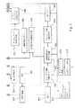
図2は本発明に基づいて修正された、図1と類似のモバイル端末10を示す。対応する部品には対応する参照番号が付されている。図2の端末10は付加的に、受信(ダウンリンク/音声デコード)ブランチ14内に配置されたノイズ・サプレッサ44を備えている。ノイズ・サプレッサ44は、DTXハンドラ36と欠陥フレームハンドリングユニット38とに接続されていることを付記しておく。ノイズ・サプレッサ44は、後述するように、その動作に影響を及ぼすDTXハンドラ36と欠陥フレームハンドリングユニット38とからの信号を受信する。音声エンコード・ブランチおよび音声デコード・ブランチ内のノイズ抑制ユニットは、図2では別個のブロック(20および44)として示されているが、これらを単一のユニットとして実装してもよいことを付記しておく。このような単一ユニットは音声エンコードおよび音声デコードの双方によるノイズ抑制機能を有することができる。
【0083】
ノイズ・サプレッサ44は、受信(音声デコード)ブランチ14内における音声デコーダ(この例では音声デコーダ34)の出力に配置されている。従って、これは例えば、1またはそれ以上の携帯電話システムの両端のモバイル相互間の接続における、1またはそれ以上の音声コーディングおよびデコーディング段に起因するノイズを含む音声信号を、処理しなければならない。
【0084】
ノイズ・サプレッサ44はモバイル端末内に示されているが、これはネットワーク内に配置してもよいことが理解されよう。後に説明するように、その動作は音声エンコーダ、音声デコーダ、またはコーディックと連係して使用されるのに特に適している。
【0085】
図3はノイズ・サプレッサ300の詳細を示す。ノイズ・サプレッサ300は、モバイル端末によって受信と送信の双方がなされる信号中のノイズを抑制するために利用することができ、従って図2のモバイル端末10内のノイズ・サプレッサ20またはノイズ・サプレッサ44のベースを形成可能である。ノイズ・サプレッサ300は機能ブロックの形式で示されている。フレーム処理および高速フーリエ変換(FFT)動作を実行するための機能ブロックも含まれている。
【0086】
アップリンク(音声エンコード)ブランチでは、A/Dコンバータ18がディジタル・データのストリームを生成し、このストリームはノイズ・サプレッサ20へと送られて、そこで入力フレームへと変換される。ここで図3を参照してこの入力フレームの生成について説明する。80サンプル・フレームの入力シーケンス312が、入力シーケンス形成ブロック316内の入力ストリーム314から抽出される。入力シーケンス312は、入力オーバラップ・セグメント・バッファ318に記憶されている18サンプル・シーケンスに追加される。この18サンプル・シーケンスは、先行する入力シーケンスの作成中にバッファ318に記憶されたものである。バッファ318のコンテンツが、新たな入力フレーム用に一旦利用されると、これらは新たな入力シーケンスの最後の18サンプルに置き換えられ、それは次のフレームの作成に利用される。このように、入力シーケンス形成ブロック316の出力は、全部で98のサンプルを含むシーケンスである。
【0087】
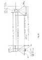
ブロック320で、98サンプル台形ウインドウ関数が、入力シーケンス形成ブロック316から獲得された入力シーケンス312に適用される。ウインドウ関数は図4に示されており、記号W1が付されている。図4は更に、後述する別のウインドウ関数W3をも示している。ウインドウ関数W1は、12サンプル長の前傾斜と後傾斜とを有している。ウインドウイングの後、結果として生じた入力シーケンスに30のゼロが追加されて、128サンプルの入力フレームが作成される。ここに記載したゼロ・パディング動作によって2の累乗、この場合には27 のサンプル数を有する入力フレームが生成されることに留意されたい。それによって、後続の高速フーリエ変換(FFT)および逆高速フーリエ変換(IFFT)の動作を確実かつ効率的に実行することができる。
【0088】
ブロック322で、フレームの周波数スペクトルを抽出するために、入力フレームに対し128ポイントのFFTが実行される。振幅スペクトルは、FFT長によってもたらされる周波数分解能よりも粗い所定の周波数分割を利用して複素FFTから計算される。この分割によって決定される周波数帯域は「計算周波数帯域」と呼ばれる。振幅スペクトルの評価には、信号の周波数分布に関する情報が含まれ、この情報は、計算周波数帯域用のノイズ抑制利得係数を計算するためにノイズ・サプレッサ44内で利用される(ブロック328)。ある程度、この計算の目的は、バックグラウンド・ノイズの周波数スペクトルの評価を確立し、かつ保持することにある。
【0089】
ブロック330では、ブロック322からの出力として供給される複素FFTに、計算周波数帯域内で、ブロック328からの対応する利得係数が乗算される。最後に、修正された複素スペクトルが、ブロック366内の逆FFTを利用して、時間領域へブロック328から逆変換される。
【0090】
計算のためのロードおよびメモリの必要性、およびウインドウイング動作のアルゴリズム遅延は、短いオーバーラップ・セグメントを有する簡単な台形ウインドウ関数によって縮減できることは公知である。しかし、このような簡単なウインドウ関数を用いることによって、出力信号に不都合な作用が生ずることがある。それらの作用のうちの最も重要なものは、短い、オーバーラップ・フレームの境界で(例えば信号レベルおよびスペクトル・コンテンツ内で)、不整合に起因して誘発されるバチバチという雑音である。このアーティファクトは、利得関数が計算周波数帯域の間で大きく変動する減衰利得を呈する中程度の入力SNRの条件下で、発生することがある。ノイズ・サプレッサが例えばアップリンク(音声エンコード)ブランチ内で、音声エンコーダの前の事前処理段として動作する場合、前記のバチバチという雑音は、一般には音声コーディング−デコーディング・プロセス自体によってマスクされる。
【0091】
しかし、図2のモバイル端末10の場合は、ノイズ・サプレッサ44の下流側に位置するそれ以上の音声エンコード段は存在しない。このように、短いオーバーラップ・セグメントを有する台形ウインドウ関数の利用に誘発される不都合なアーティファクトは、後続のエンコード・プロセスによっては遮蔽されず、スピーカ/イヤピース42に送られる出力信号中で耳に聴こえる。この問題点を克服するため、オーバーラップ・セグメントの長さを長くし、ウインドウ関数を平滑化することも可能ではあるが、それによって計算の複雑さが増し、特にアルゴリズム遅延が増すことになろう。
【0092】
従って、本発明により、フレームの境界領域のアーティファクトを抑制するために改良されたオーバーラップ加算手順によって、出力時間領域フレームが形成される。これはウインドウ関数W1およびW2によって表される。特性が僅かに異なる少なくとも2つの台形ウインドウ関数の組合せが使用される、「2段階」ウインドウイング構成が適用される。一方のウインドウ関数はFFTに入力されるウインドウイング・フレーム用であり、他方のウインドウ関数はIFFTから出力されるウインドウイング・フレーム用である。本発明の方法では、比較的長く、ゆるやかな傾斜を有する第1の台形ウインドウ関数W1が、ブロック322でFFTが実行される前にブロック320で、入力信号に適用される。入力信号がブロック366でIFFTによって時間領域へと逆変換されると、IFFTの出力はブロック368で、FFTより前に利用されたウインドウ関数よりも短く、かつ急な傾斜を有する第2の台形ウインドウ関数W2によって修正される。オーバーラップ追加セグメントの長さは、第2の先細のウインドウの傾斜の長さによって決定される。ウインドウ関数W1とW3は図4に示され、比較できる。
【0093】
W2は、6サンプル長の、前傾斜および後傾斜関数を有する86サンプル長である。この第2ウインドウの始端は、IFFT出力シーケンスの6番目のサンプル(ベクトル)と同期化され、傾斜関数は、ウインドウの両端で6サンプル長の線形傾斜を生成するような傾斜関数である。この動作による出力は86サンプルのベクトルであり、そのうちの最初の6サンプルはブロック372で、先行のフレームの処理中に記憶された同じサイズの、出力オーバーラップ・セグメント・バッファ370からのサンプルとサンプルごとに合計される。次に、ウインドウ出力ベクトルの最後の6サンプルが、次のフレームで使用されるように、出力オーバーラップ・セグメント・バッファ370に記憶される。ブロック374で、出力フレームは最終的にウインドウ出力の最初の80サンプルとして抽出され、それには最初の6サンプルと、先行する出力オーバーラップ・セグメント・バッファからのサンプルとの前述の合計も含まれる。
【0094】
前述の2段階の台形ウインドウイング・プロセスは、音声デコーディングの後の事後処理段として使用されるノイズ・サプレッサと連係して利用してもよく、または、音声エンコードに先立つ事前プロセッサとして使用されるノイズ・サプレッサに適用してもよいことに留意されたい。特に、音声エンコーダの入力で2段階ウインドウによってもたらされる向上したクオリティは、音声エンコード・プロセスで達成されるクオリティを高めることができる。
【0095】
FFT用の入力ベクトルは、実際には実数からなっているので、Numerical Recipes(数値計算法) CのThe Art of scientific Computing(414−415ページ、1988年刊)に記載されているような三角再結合方式(trigonometric recombination method)を利用して、2つの入力フレームを1つの複素FFTにパックすることによって計算負荷を低減することができる。このアプローチでは、ウインドウイングされ、ゼロ・パディングされた第1のフレームのサンプルは、FFT用の入力シーケンスの実数成分に割当てられる。第2フレームは入力シーケンスの虚数成分に割当てられる。次に128ポイントの複素FFTが計算される。2つのフレームの複素スペクトルは、三角再結合によって分離することができる。2つの複素スペクトルのノイズ低減処理の後、これらは第1スペクトルに虚数単位で乗算された第2スペクトルを加算することによって合成される。その結果生じた複素スペクトルはIFFTに送られ、出力時間領域フレームを、IFFT出力の実数部分と虚数部分とに見いだすことが可能である。
【0096】
近似振幅スペクトルはブロック326で複素FFTから計算される。各FFTビン(bin)内で、複素値が2乗されて、そのビンについてのエネルギ値が算出される。各々の計算周波数帯域内での2乗されたFFTビンの値は合計された後、平方根がとられて、各計算周波数帯域ごとの近似平均振幅が算出される。全く類似した方法でパワー・スペクトル値を用いることもできることが理解されよう。
【0097】
バックグラウンド・ノイズ・スペクトル評価は、ブロック326の出力として獲得された近似振幅スペクトル表現に基づくものである。バックグラウンド・ノイズ・スペクトル評価を更新する手順については後述する。
【0098】
本発明の好適な実施形態では、0Hzから4kHzまでの周波数範囲が、幅が等しくない12の計算周波数帯域へと分割される。この分割は、音声中のホルマント周波数の平均位置に関する統計的知識に基づくものである。計算周波数帯域にわたりスペクトル値を平均するプロセスは、処理されるべきスペクトル・ビンの数を効果的に縮減し、ひいてはアルゴリズムの計算負荷を縮減して、スタティックRAMおよびダイナミックRAMの双方において節減する結果をもたらす。その上、周波数領域内での加算平均には、向上した音声を平滑化する効果がある。しかし、これらの利点は周波数分解能の犠牲のもとに得られるものであるので、折衷が必要である。特に、バックグラウンド・ノイズが音声信号と同じ周波数領域にある場合は、周波数分解能は音声とノイズとを充分に分離するだけ高くなければならない。
【0099】
ここで、ノイズ・サプレッサ44内で行われるノイズ抑制プロセスの動作を説明する。ノイズ抑制は、付加的なバックグラウンド・ノイズによって劣化した音声信号の向上に関するものである。本発明によれば、ノイズ抑制は、ノイズを含む音声信号のスペクトル評価を計算し、バックグラウンド・ノイズのスペクトルを評価し、かつノイズを含むオリジナル音声よりもノイズ・レベルが低い、ノイズを含む音声スペクトルを向上(enhance)させる試みによって、実行される。
【0100】
ノイズ・サプレッサ44内では、修正されたWienerフィルタリングが用いられる。各計算周波数帯域ごとの利得係数は、入り(現在の)音声フレームとバックグラウンド・ノイズとに対する振幅スペクトル評価を利用して、ブロック344で計算された事前(a priori)SNR評価に基づいて、ブロック328で計算される。次にブロック351でこれらの利得係数に基づく補間が行われ、利得係数がその中に存在する計算周波数帯域に応じて各FFTビンに利得係数が与えられる。最低計算周波数帯域のより低い周波数未満の、FFTビン用の利得係数が、その最低計算周波数帯域の利得係数をもとに決定される。同様にして、最高計算周波数帯域のより高い範囲以上のFFTビンに適用される利得係数が、その最高計算周波数帯域用の利得係数を用いて決定される。ブロック330で複素スペクトル成分に対応する利得係数が乗算される。ノイズ・サプレッサ44では、利得係数値は〔lowgain,1〕の範囲にある。但し、オーバーフローに関する処理の制御を簡略にするために0<lowgain<1である。
【0101】
任意の周波数ビンθに対するWiener振幅評価のための利得計算式は下記のように表される。
【0102】
【数1】
【数2】
【0103】
ここで導入したWienerフィルタリングの修正には、各計算周波数帯域に対する事前SNRが評価される方法も含まれている。オリジナルの音声信号およびノイズ信号自体は事前には分からないので、基本的に、単チャネル信号から真の事前SNRを抽出する方法はない。
【0104】
事前SNRの評価はブロック344で行われる。先行技術では、事前SNRは前述の決定志向的なアプローチを用いて評価することができ、これは数学的に下記のように表すことができる。
【0105】
【数3】
数式3では、γ(s,n) は、ブロック342で現在のフレームのパワー・スペクトルの成分と、計算周波数帯域sについてのバックグラウンド・ノイズのパワー・スペクトルとの比率として計算された、フレーム数nの事後(posteriori)SNRである。このパワー比はそれぞれの振幅スペクトル評価の対応する成分の比率を2乗することによって計算される。G(s,n-1) は以前のフレームについて決定された計算周波数帯域の利得係数である。P(・)は整流関数(rectifying function)であり、αはいわゆる「忘却要素」(forgetting factor)(0<α<1)である。決定志向的なアプローチによって、αは現フレームのVAD判定に応じて2つの値の1つをとることができる。
【0107】
事前SNRはSNRが高い条件で、より一般的には、音声が明確に存在するか、または、全く存在しない周波数帯域で、正確に評価することができる。しかし、数式1で示されたWiener評価式はSNRの低い値に向かって大きく増大する導関数を有し、また数式3によって与えられる評価は低いSNRの値では完全に正確ではないので、数式1によって表されたWiener評価式を直接適用すると、ある程度の音声が存在する場合には低SNR周波数帯域で悪影響を生ずる。音声の歪みに加えて、中程度のノイズ・レベルで音声発語中に、残留ノイズは妨害になるほど不安定になる。
【0108】
本発明では、前述した従来の音声/ノイズ比に代えて、ノイズを含む音声とノイズとの事前比率が評価される。以下の説明では、このノイズを含む音声とノイズとの比は略語NSNRを用いて示す。事前SNRの単純なそのままの評価ではなく、事前NSNRの評価を用いることによって、ノイズ抑制された音声信号の主観的(知覚される)クオリティは著しく高まる。
【0109】
このように、本発明に基づいて、事前SNRの評価の代わりに、ノイズを含む音声/ノイズ比、NSNR、の評価が用いられ、数式3に代わる下記の公式が得られる。
【0110】
【数4】
NSNRは事前音声/ノイズ比、SNR、よりもより正確に評価できるということを主張する。数式4に基づいて、以前のフレームについて得られ、以前のフレームのそれぞれの利得係数が乗算された事後SNR値は、現在のフレームに対する事前のノイズを含む音声/ノイズ比の計算に用いられる。各フレームに対する事後SNR値は、そのフレームに対する利得係数の計算後にSNRメモリ・ブロック345に記憶される。このように、以前のフレームについての事後SNR値をSNRメモリ・ブロック345から検索し、現行フレームの事前NSNRの計算に用いることができる。
【0112】
本発明に基づいて、数式4によって与えられるNSNR評価も、数式5に示されるように、下記により制約される。これは獲得できる最大ノイズ減衰に対し効果的に上限を設定する。
【0113】
【数5】
約10dBの最大減衰を生じる閾値ξmin を選択し、かつWiener利得方程式に、ハット付きの上記ξ(s)を代入することによって、(ノイズ抑制後に残るノイズ成分である) 残留バックグラウンド・ノイズは平滑になり、音声の歪みは著しく低減する。
【0115】
数式4中の忘却要素αはまた、先行技術のノイズ抑制方式とは異なって処理される。VAD判定に基づいて忘却要素αを選択する代わりに、これは現行のSNR条件に基づいて判定される。この特徴は、SNRが低い条件では、事前NSNR評価の時間領域の平滑化によって、ノイズが抑制された音声のクオリティに対する評価エラーの悪影響を軽減することができる、という事実に誘発されるものである。忘却要素と現行のSNR条件との関係を確立するために、下記の数式6で示される反転された(inversed)事後SNR表示、snrapIn 、に基づいてαが計算される。
【0116】
【数6】
【0117】
音声レベル評価を得るため、現在の音声フレームのパワー・スペクトルは計算周波数帯域にわたって加算平均される。フレーム・パワーは、可変忘却要素と可変フレーム遅延でフィルタリングされ、ノイズを含む音声レベルの評価がなされる。ノイズ・レベル評価は、計算周波数帯域にわたってバックグラウンド・ノイズ・スペクトル評価を加算平均し、かつ時間経過とともに固定忘却要素でフィルタリングすることによって得られる。
【0118】
ノイズ・サプレッサ44はまた、後述するようにバックグラウンド・ノイズ・スペクトル評価の更新プロセスを制御するために使用される音声アクティビティ検出器(VAD)336をも備えている。音声アクティビティ検出は主としてバックグラウンド・ノイズ・スペクトルの評価を制御するためにノイズ・サプレッサ44内で使用される。しかし各フレームごとのVAD336の判定は、(前述の)事前NSNR評価に関連したノイズを含む音声とノイズのレベルの評価、および(後述する)利得計算における最小限の検索手順のような他の幾つかの機能を制御するためにも利用される。その上、VADアルゴリズムを利用して、外部目的のための音声検出表示を行うこともできる。VAD表示の動作は、VADの感度を増減するためのパラメータ値の変更のような僅かな修正を行うことによって、ハンズフリーのエコー制御または間欠送信(DTX)機能のような外部機能用に、最適化することができる。
【0119】
音声を含むフレーム内だけでの、ノイズを含む音声レベル評価を更新するために、現行のフレームおよび近傍のフレーム中に、VAD336によって、音声アクティビティが検出されるか否かに応じて、更新が許容されたり禁止されたりする。更新パワーが得られるフレームの前と後の双方で、VAD336の判定を監視できるように、遅延が導入される。このような対策を講じることによって、ノイズを含む音声と純粋なノイズとの間の遷移を表すフレーム内において小パワーの音声レベル評価に与える影響を、軽減することができ、また、これらのフレーム内でのVAD336本来の信頼性の欠如を補償することができる。実際には、遅延はフレーム・パワーが極めて大きいフレームを除いては2フレームに設定され、前記のような場合は、VAD336が音声を検出する最新の3フレームのうちの最小の2フレームが選択される。
【0120】
ノイズを含む音声パワーの平均範囲を表すフレーム・パワーによる更新を有利にするために、現行のフレーム・パワーと先行する音声レベル評価との差が、定数項(absolute term)で、小さい場合は、忘却要素は、最速の更新を可能にするような値をとる。
【0121】
ノイズ・レベル評価は、フレームごとにバックグラウンド・ノイズ・スペクトル評価における全パワーをフィルタリングすることによって得られる。この場合は、VADに準拠した付加的な条件は設定されず、ノイズ・スペクトル評価の更新手順は既に充分に信頼できるので、忘却要素は一定に保たれる。
【0122】
最後に、SNR補正係数(correction coefficient)として用いられる相対ノイズ・レベル・インジケータが定義される。これは、下記の数式7に示すように、ノイズ・レベル評価とノイズを含む音声レベル評価との、スケーリングされかつ制限された比率として定義される。
【0123】
【数7】
【0124】
前述のノイズ・レベル評価(ハット付きのN)は起動時にゼロに設定される。前述のノイズを含む音声レベル評価(ハット付きのS)は、中程度に低い音声パワーに対応した値に初期設定される。後続の処理ではノイズを含む音声レベル評価のための最小値として別のやや小さい値が用いられる。
【0125】
SNR補正は数式8に従って事前NSNR評価に適用される。
【数8】
これにより、数式2に代入される修正された事前NSNR評価が得られる。
【0127】
所定の音声フレーム中の音声アクティビティの検出は、ノイズ・サプレッサのブロック342で計算された事後SNR評価に基づいて行われる。基本的に、VAD判定は、スペクトル距離尺度DSNR を適応閾値vthと比較することによって行われる。スペクトル距離DSNR は、事後SNRベクトルの成分の平均として計算される。
【0128】
【数9】
【0129】
DSNR が閾値vth を超えると、そのフレームは音声を含んでいるものと解釈され、VAD関数は「1」を示す。そうではない場合は、フレームはノイズとして分類され、VADは「0」を示す。これらの2進数よるVAD判定は、過去のVAD判定を参照できるように、16フレーム(1つの16ビット静的変数)にわたるシフトレジスタに記憶される。
【0130】
VAD閾値vth は通常は一定である。しかしSNRの条件が極めて良好な場合は、信号パワー中の僅かな変動が音声であるものと見なされることを防止するために、閾値は増分される。(前述の)相対ノイズ・レベルηの値が小さいと、SNRの条件が良好であることを示す。なぜなら、その要素は、評価されたノイズを含む音声パワーに対する評価されたノイズ・パワーのスケーリングされた比率だからである。このように、ηが小さい場合は、VAD閾値vht はηの負数に対して直線的に増加する。ηに関する閾値は、ηが閾値よりも大きい場合は、vht が一定に保たれるようにも定義される。
【0131】
入力信号パワーが極めて低い場合は、前述ように、VAD閾値に適応後でも信号中の固定的ではない小さい事象が、誤って音声であると見なされる場合がある。このような音声の誤検出を抑止するため、入力信号フレームの全パワーが閾値と比較される。フレーム・パワーが閾値未満に留まっている場合は、VAD判定は、音声がないことを示すために強制的に「0」にされる。しかし、この修正は、以前の評価の重みと、数式4における新たなフレームの事後SNRとを判定するために、VAD判定が事前NSNRに適用された場合だけ実施される。バックグラウンド・ノイズ・スペクトル評価と、ノイズを含む音声およびノイズのレベル評価とを更新する目的のため、また、(後述する)最小限の利得検索において、16ビットシフトレジスタ内の不変のVAD判定が用いられる。
【0132】
音声中の遷移に対する良好な応答を確実にするためには、数式2を用いてブロック328で計算されたノイズ減衰利得係数は、音声アクティビティに迅速に反応するものである必要がある。残念ながら、音声の遷移に対する減衰利得係数の感度が高まると、非固定的ノイズに対する感度も高まってしまう。その上、バックグラウンド・ノイズ振幅スペクトルの評価は反復的なフィルタリングによって行われるので、評価は急激に変化するノイズ成分に迅速に適応できず、ひいてはそれらを減衰させることができない。
【0133】
利得係数ベクトルのスペクトル分解能が高まると、同時にパワー・スペクトル成分の加算平均も低減し、すなわち計算周波数帯域当たりのFFTビンの数がより少なくなるので、残留ノイズの不都合なバリエーションも生じてしまう可能性が高まる。しかし、計算周波数帯域を広くすると、ノイズが集中する周波数をアルゴリズムが突き止める能力が低くなる。それによって特に、一般にノイズが集中する低周波数では、ノイズ・サプレッサの出力に不都合な変動が生ずることがある。更に音声中の低周波コンテンツの比率が高いと、音声を含むフレーム内の同じ低周波範囲でノイズ減衰が低減し、その結果、音声のリズムと同期する残留ノイズの不都合な変調が生ずる傾向がある。
【0134】
本発明によれば、上記に概述した問題点は「最小利得検索」を用いて対処される。これはブロック350で実行される。現在のフレーム、および(利得メモリ・ブロック352に記憶されている)1またはそれ以上の以前のフレームについて判定された減衰利得係数G(s))が吟味され、各計算周波数帯域sごとの減衰利得係数の最小値が特定される。どれほど多くの以前の減衰利得係数ベクトルを吟味するかを限定する際に、現在のフレームに関するVAD判定が考慮されて、現在のフレーム内に音声が検出されない場合には、2組の以前の減衰利得係数が検討され、また現在のフレーム内に音声が検出された場合には1組の以前の減衰利得係数だけが検討されるようにされる。最小利得検索のプロパティは下記の数式10に要約される。
【0135】
【数10】
【0136】
最小利得検索には、ノイズ抑制アルゴリズムの機能をスムーズにし、かつ安定させる傾向がある。その結果、残留バックグラウンド・ノイズはよりスムーズに響き、急激に変化する非固定的(non-stationary)ではないバックグラウンド・ノイズ成分は、効率的に減衰される。
【0137】
既に説明したように、周波数領域内でノイズ抑制を適用する場合、バックグラウンド・ノイズ・スペクトルの評価を得る必要がある。ここでこの評価プロセスをより詳細に説明する。本発明によって、バックグラウンド・ノイズ・スペクトルの評価は、音声アクティビティが存在しない期間中に入力信号フレームの周波数スペクトルを加算平均することによって得られる。これは、暫定的なバックグラウンド・ノイズ・スペクトル評価を計算するブロック332と、最終的なバックグラウンド・ノイズ・スペクトル評価を計算するブロック334で行われる。このアプローチによって、VAD336の出力を参照して、バックグラウンド・ノイズ・スペクトル評価の更新が行われる。音声が存在しないことをVAD336が示した場合は、現在のフレームの振幅スペクトルに所定の重み付けがなされて、忘却要素を乗算した以前のバックグラウンド・ノイズ・スペクトル評価に加算される。これらの作用は以下の数式11によって示される。
【0138】
【数11】
【0139】
忘却要素は、振幅スペクトルを利用して、数式11によって与えられるノイズ統計の更新により、効率的に対処できるように構成されている。上向き(upward)更新用には、振幅領域でより小さい忘却要素で比較的早い時定数が用いられ、下向き(downward)の更新用には、より遅い時定数が用いられる。時定数も、大きい変化と小さい変化に適応するように変更される。スペクトル成分が以前の評価よりも大幅に大きい値で更新されなければならない場合には、上向き方向で急激な更新が行われ、また、新たなスペクトル成分が以前の評価よりも大幅に小さい場合には、下向き方向で緩やかな更新が行われる。一方、以前の評価に近いスペクトル成分値を更新するには、やや遅い時定数が用いられる。
【0140】
VAD336は2値出力を供給するだけなので、発語(utterance)の開始の識別にはトレードオフが含まれる。音声発語の開始時に、VAD336はノイズのフラグを立て続けることがある。このように、音声の最初のフレームがノイズとして誤って分類され、その結果、バックグラウンド・ノイズ・スペクトル評価が、音声を含むスペクトルで更新されることがある。同様の状態が発語の終了時にも生ずることがある。
【0141】
後に詳述するように、この問題点は、ブロック334でバックグラウンド・ノイズ・スペクトル評価を更新するために用いられるフレームに先行するフレームの前と後に、VAD336からの判定ウインドウを遮蔽することによって対処される。次に、バックグラウンド・スペクトルを、記憶された以前のフレームの振幅スペクトルによって、遅延を伴って更新(遅延された更新)することができる。
【0142】
本発明によって、バックグラウンド・ノイズ・スペクトル評価の更新は2段階で行われる。最初に、現行フレームの振幅スペクトルでバックグラウンド・ノイズ・スペクトル評価を更新することによって、ブロック332で暫定パワー・スペクトル評価が行われる。この更新プロセスを行うには、以下の3つの条件のうち1つが満たされる必要がある。
【0143】
1.現在の、および以前の3つのフレームのVAD336の判定が「0」である(ノイズだけを示す)。
2.信号が必要なフレーム数について固定的(stationary)であると判定される。
3.現在のフレームのパワー・スペクトルが、何れかの周波数帯域でのバックグラウンド・ノイズ・スペクトル評価よりも低い。
【0144】
第2に、後続のフレームでのVAD判定が「1」であり、かつその前の(すなわち直前の)3つのフレームがVAD判定「0」を生じない限りは、(ブロック332から)生じた暫定パワー・スペクトル評価が後続フレームの実際のバックグラウンド・ノイズ・スペクトル評価として用いられる。そのような場合は、対応して、例えば発語の開始時に、以前のバックグラウンド・ノイズ・スペクトル評価がブロック334からブロック332での暫定パワー・スペクトル評価へとコピーされて、評価がリセットされる。
【0145】
バックグラウンド・ノイズ・スペクトル評価プロセスはVAD336の判定によって制御されるが、VAD336の判定自体がブロック334におけるバックグラウンド・ノイズ・スペクトル評価に依存していることによる困難が生ずることもある。バックグラウンド・ノイズ・レベルが急激に高くなると、入力フレームが音声と見なされ、バックグラウンド・ノイズ・スペクトル評価の更新が行われない。それによって、バックグラウンド・ノイズ・スペクトル評価が実際のノイズを見失ってしまう。
【0146】
この問題に対処するには、修復方式(recovery method)が用いられる。VAD336が音声として分類している期間中に、ブロック338で入力信号の固定度(stationarity)が評価される。「音声誤検出カウンタ」と呼ばれるカウンタが、VAD336からの連続的な「1」の判定の記録を保存するために、ブロック339に保持される。最初に、カウンタは0.5秒(50フレーム)に対応して50に設定される。入力信号が充分に固定的(stationary)であると見なされ、かつ現行フレームが音声であると見なされると、音声誤検出カウンタがカウントダウンされる。固定度が示され、VADが現行フレームについて「0」を出力し、しかし、以前の幾つかのフレームに「1」が示されるフレームが有る場合は、カウンタは修正されない。入力信号が固定的ではないものと判定されると、カウンタは初期値にリセットされる。カウンタがゼロに達するごとに、ブロック334におけるバックグラウンド・ノイズ・スペクトル評価は更新される。最後に、12回連続で「0」のVAD判定が得られた場合も、音声誤検出カウンタはリセットされる。この動作は、「0」のVAD判定のこのような連続が、ブロック334におけるバックグラウンド・ノイズ・スペクトル評価が再び現行のノイズ・レベルに達したことを暗示する、という想定に基づいている。
【0147】
現行のフレームが固定的な信号を呈するか否かを判定するために、反復的な加算平均によって入力信号の振幅スペクトルの短期の加算平均がブロック340に保存される。現行フレームの振幅スペクトル成分は時間平均スペクトルの対応する成分で除算され、何れかの商が1未満になった場合は、その代わりに逆数(reciprocal)に置き換えられる。結果としての合計が所定の閾値を超えた場合は、信号は固定的なものではないものと判定される。そうではない場合は、固定度が判定される。(反復加算平均によってブロック340に保存されている)振幅スペクトルの短期平均の成分は、入力フレームの振幅スペクトルよりもやや遅く変化するので、ゼロに初期設定される。
【0148】
前述のVADをベースにした基本的な更新アプローチ、および修復方法に加えて、現行フレームの振幅スペクトルの対応成分が現行のバックグラウンド・ノイズ・スペクトル評価よりも小さい場合には、全てのフレームにおけるバックグラウンド・ノイズ・スペクトル評価の成分が更新される。それによって(1)(後述の)バックグラウンド・ノイズ・スペクトル成分の大きい初期値、および(2)実際の音声フレーム中に生ずることがある誤った強制更新からの迅速な修復が可能になる。「ダウン更新」(down-up-dating)と呼ばれるこの付加的な更新形式は、ノイズ独自では、ノイズ、プラス音声よりも高い振幅を有することは決してない、という事実に基づいている。ダウン更新は、ブロック332における暫定バックグラウンド・ノイズ・スペクトル評価を更新することによって行われる。
【0149】
始動時に、ブロック334内のバックグラウンド・ノイズ・スペクトル評価成分は、より高い振幅を表す値に初期設定される。このようにして、バックグラウンド・ノイズ・スペクトル評価がノイズを見逃すという問題に遭遇することなく、予測される広範囲の初期入力信号に適応できる。同じ初期設定が、遅延された更新に用いられるブロック332での暫定バックグラウンド・ノイズ・スペクトル評価にも、適用される。
【0150】
ノイズ・サプレッサ44の動作は、ノイズをダウンリンク方向に効率的に抑制できるように制御される。特に、その動作は、信号パワーおよび振幅レベルの評価、特にブロック334におけるバックグラウンド・ノイズ・スペクトル評価が誤って修正されないように制御される。このような誤修正は、送信チャネル・エラーの結果発生することがある。チャネル・エラーは、例えば数10フレーム、またはそれ以上の多数のフレームの破損、または損失の原因になることがある。前述したように、チャネル・エラーが検出されると、これらは標準的には直前の良好な音声フレームを反復(またはそこから外挿)すると同時に、一方では急激に増加する減衰を加えることによって隠蔽される。
【0151】
フレームが受信されていない期間中には音声もノイズも受信されず、従ってブロック332における暫定バックグラウンド・ノイズ・スペクトル評価およびブロック334におけるバックグラウンド・ノイズ・スペクトル評価は減少する傾向がある。その結果、ノイズ・サプレッサ44は真のノイズ・スペクトルを見逃すことがある。この作用を補償する手段が講じられないと、チャネルがクリアされ、フレームが再び適正に受信される際に、低減したバックグラウンド・ノイズ・スペクトル評価に基づいてノイズ抑制が行われてしまうことがある。従って、ノイズ・サプレッサによるノイズ抑制は効果的ではなくなり、モバイル端末のユーザが聴くノイズ・レベルは突然上昇するであろう。その上、このような中断の後、ブロック332および334は、精度を回復するために、真のノイズ・スペクトルに基づいてバックグラウンド・ノイズ・スペクトルの評価を再構築しなければならない。再び適正な評価が得られるまで、ノイズ評価は不適正なものになり、ユーザにはノイズの種類の突然の変化として聴こえてしまう。ノイズの種類、およびノイズ・レベルのこのような変化はユーザには煩わしいものである。
【0152】
加えて、エラーの検出に失敗したエラー音声フレームによって、音声デコーダ34が、不規則に分布する高レベルのエネルギを有する誤音声フレームを出力する原因になる。ノイズ・サプレッサ44はこのようなフレーム内の信号を減衰することはできない。
【0153】
関連する問題は、間欠送信(DTX)または音声作動切換え(VOX:Voice Operated switching)のような、何れかの同様の機能を使用することによって誘発される。前述したように、DTXの間、コンフォート・ノイズ・スペクトルが生成され、真のノイズの代わりにコンフォート・ノイズが再生される。コンフォート・ノイズのスペクトルが真のノイズ・スペクトルと異なっている場合、例えばコンフォート・ノイズの再生中に真のノイズ・スペクトルが変化した場合は、ブロック334におけるバックグラウンド・ノイズ・スペクトル評価は真のノイズ・スペクトルを見逃してしまう。その結果、DTXが中断され、音声を含むフレームが再度受信されると、ノイズ・サプレッサ44は以前には妥当であったバックグラウンド・ノイズ・スペクトル評価を用いて、受信信号中のノイズの抑制を開始する。そのため、減衰は最適なものではなくなる。
【0154】
欠陥のある音声フレームおよびDXTの作用に起因するこのような問題点に対処するため、これらの作用は、ノイズを含む音声のレベルの長期的な評価の更新、またはVAD336および最小利得検索機能においても考慮される。
【0155】
本発明の実施形態によって、アップリンク・チャネルとダウンリンク・チャネルの双方に配置されたノイズ・サプレッサを有する携帯電話が提供される。2台のこのような携帯電話が通信する通信システムでは、信号はカスケード配列された多数のノイズ・サプレッサを通過する。更に、例えばスイッチ、トランスコーダ、またはその他のネットワーク装置のようなセルラー・ネットワークでもノイズ・サプレッサが使用される場合は、カスケード内には更に多くのノイズ・サプレッサが存在する。このようなノイズ・サプレッサは一般に、音声に障害になる歪みを誘発せずにノイズを最大限に減衰するように個別に最適化される。しかし、このようなカスケード内で2つ、またはそれ以上のノイズ抑制動作を用いた場合は、音声の歪みを誘発する。
【0156】
本発明の1実施形態では、ノイズ・サプレッサ44には、入力を分析して、音声経路内で以前にノイズ・サプレッサを使用したことを考慮に入れるための検出器が備えられる。検出器はダウンリンク(音声デコード)経路内のノイズ・サプレッサ44の入力におけるSNR状態を監視し、評価されたSNRに基づいて減衰利得の計算を制御する。SNR状態が良好である場合は、これらの状態は以前のノイズ低減段階の結果であると思われるので、ノイズ抑制は低減され、または全く行われない。いずれにせよ、SNR状態が良好な場合は、一般にノイズ抑制の必要性は少なくなる。
【0157】
信号依存型の利得制御のための制御変数は、ノイズを含む音声パワーとバックグラウンド・ノイズ・パワーとの長期的評価の比率としての、ノイズ・サプレッサ入力信号の有効全帯域の事後SNRを評価することによって、設定される。全帯域の事前SNRはブロック348で計算される。「有効全帯域」(effective-full-band)という用語は、利得計算時に、計算周波数帯域によってカバーされる周波数範囲を意味する。実際的な理由から、実際のSNRの代わりに事後SNRの逆数が評価される。このアプローチが用いられる主な理由は、ノイズ・パワーはノイズを含む音声パワーよりも小さいか、これに等しいことを常に想定できるからである。それによって固定小数点数演算の計算が簡略化される。
【0158】
事後SNR、すなわちsnrapiは前述したように、ノイズと、ノイズを含む音声のレベル評価、ハット付きのNとハット付きのS、の比率として計算される。この場合は、ノイズ・レベルと、ノイズを含む音声のレベルとの比率は、SNR補正係数の計算(数式7)の場合のようにはスケーリングされず、音声フレーム全体にわたって低域通過フィルタリングされる。フィルタリングの目的は、減衰制御をスムーズにするために、音声またはバックグラウンド・ノイズのレベルの急激な変化の作用を軽減することにある。制御変数snrapiの評価は下記のように表される。
【0159】
【数12】
【0160】
良好なSNR状態でのノイズ減衰を制限するための制御メカニズムは、デシベル(dB)単位の減衰が、デシベル単位のSNRの上昇に対し直線的に低下するように、考案されたものである。この計算方法は、聞き手には知覚できないようなスムーズな遷移を目的とするものである。その上、制御は限定された入力SNRの範囲に制限される。
【0161】
減衰の低減は、Wiener利得式のバックグラウンド・ノイズ・スペクトルの項の過小評価によって実現される。数式2の代わりに、修正された利得計算式が用いられる。
【0162】
【数13】
制御変数snrapiに対する単位項(unity term)u(snrapi)の依存性は、最大の減衰時に、比例関係をdBスケールで表すことによって見いだすことができる。次に下記の関係式を導出することができる。
【0164】
【数14】
【0165】
競合する2つの利得制御メカニズムに適応し、かつある条件で発生する最適ではない減衰を避けるため、利得制御の制御パラメータ、および特に制御変数および最大減衰範囲は、最大の利点が予期される範囲で最高のノイズ抑制が得られるように綿密に選択される。これは、SNR状態を充分に良好に評価することによるものである。
【0166】
一方はアップリンクにおける、他方はダウンリンクにおける利得関数を合成する際に問題が予測されるものの、第1の(アップリンク)ノイズ・サプレッサは、一般に第2の(ダウンリンク)ノイズ・サプレッサの入力におけるSNR状態を向上させる。従って、スムーズでかつ基本的に単調に合成された利得関数が得られるように、上記のことはタンデム接続に際して考慮されなければならない。
【0167】
ノイズ・サプレッサ44は、欠陥フレームの発生と、ノイズ・サプレッサが音声デコード後の事後処理段として動作する際に音声デコーダによりとられる関連動作と、関する情報を、利用する。
【0168】
チャネル・デコーダ32から派生する欠陥フレーム表示フラグは、各フラグが1ビット位置を確保するノイズ・サプレッサ内の制御フラグ・レジスタの適宜のエントリに割当てられる。チャネル・デコーダが欠陥フレームの存在を表示すると、欠陥フレーム・フラグが立てられ、たとえば1に設定される。そうではない場合は、フラグはゼロに設定される。
【0169】
損失された音声フレームのバーストが検出された直後、通常VAD336によって制御されるある機能は、VAD336の判定に左右されなくなる。加えて、VAD336、および以前のVAD判定を含むシフトレジスタの状態は、欠陥フレーム表示フラグが欠陥フレームの存在を表示している間は、フリーズされる。それによって、VAD336に依存する機能が、通常は短期間の欠陥フレームのバースト後に、直前の「良好な」VAD判定を、利用できるようになる。ほとんどの場合は、それによって欠陥フレームに起因するノイズ・サプレッサの性能障害が最小限になる。
【0170】
バックグラウンド・ノイズ・スペクトル評価の、適正なスペクトル・レベルおよび形状を維持するために、欠陥フレーム表示フラグが設定されている間は、前記の評価は更新されない。特に、暫定バックグラウンド・ノイズ・スペクトル評価は更新されない。しかし、前述したように、現行のVAD336の判定が「1」であり、VADの3つの「0」判定が先行している場合は、欠陥フレームがフラグ表示されている間でも、バックグラウンド・ノイズ・スペクトル評価を暫定バックグラウンド・ノイズ・スペクトル評価と置き換えることによって、バックグラウンド・ノイズ・スペクトル評価の更新が遅延される。暫定バックグラウンド・ノイズ・スペクトル評価は更新されないので、それによって実際のノイズ・スペクトルに関連する直前の妥当な情報だけが確実にバックグラウンド・ノイズ・スペクトルの評価に含まれるようにされる。
【0171】
ブロック338における固定度検出への適切な参照のために、欠陥フレームがフラグ表示されている場合は、入力信号パワー・スペクトルの短期平均は更新されない。欠陥フレーム表示フラグが設定されている間は、その状態を、一般には短い欠陥フレームの継続期間にわたって保持するために更新しない。
【0172】
反復され、減衰されたフレームで適正なバックグラウンド・ノイズ低減をなすために、欠陥フレーム・ハンドラによってデコードされた信号に対して行われる減衰を、考慮に入れる必要がある。その目的のため、(現行フレームのパワー・スペクトルを、成分ごとに分割することによって、事後SNRを生成するために使用される)バックグラウンド・ノイズ・スペクトル評価には、反復的なフレーム減衰利得が乗算される。反復的なフレーム減衰利得はブロック346で計算される。
【0173】
ブロック348で計算された、ノイズを含む音声レベル評価(ハット付きのS)は、欠陥フレームの間は無効にされる。ノイズを含む音声レベルの評価に使用される直前の2つのフレームについてのフレーム・パワーの遅延された値も、欠陥フレーム表示フラグの設定中は、フリーズされる。従って、更新手順には、直前に更新されたVAD判定に対応するフレームのパワーが提供される。
【0174】
これとは対照的に、ノイズ・レベル評価Nは、欠陥フレームの間にブロック348で継続的に更新される。この手順の動機付けは、ノイズ・レベル評価Nが、反復され減衰されたフレームの作用から上記の手法によって保護されるバックグラウンド・ノイズ・スペクトル評価に、基づいている。このように、欠陥フレーム中に経過する時間は、ノイズ・スペクトル評価の平均パワーにより近い、低域通過フィルタリングされたノイズ・レベル評価を得るために、実際に利用できる。
【0175】
最小利得検索は欠陥フレームの間は無効にされる。そうしないと、低減した利得値による利得メモリの更新によって、例えば、欠陥フレームから良好な音声フレームへの遷移にバイアスがかかり、これにより、欠陥フレームのシーケンスに続く始めの幾つかの(例えば1つまたは2つの)良好な音声フレームが、過度に減衰されてしまう。
【0176】
欠陥があるチャネル・エラーの状態では、チャネル・デコーダ32はフレームを適正に修復することはできないので、欠陥があるエラー・フレームは音声デコーダに先送りされる。標準的にはチャネル・エラーはバースト中に発生するので、欠陥フレームは通常は集合的に発生する。音声デコーダ34の欠陥フレーム・ハンドリング・ユニット38が欠陥フレームを検出し得ず、その結果、そのフレームが通常どおりにデコードされると、一般にはエネルギが高く不規則なシーケンスが生ずる結果になり、これは極めて不快に響く。しかし、このようなエラー・フレームによって必らずしも、ノイズ・サプレッサ44に問題が生ずるわけではない。標準的には高いエネルギを含むこのようなフレームについては、VAD336が音声にフラグをたてるのでバックグラウンド・ノイズ・スペクトル評価には含まれない。更に、高いフレーム・エネルギはノイズを含む音声レベル評価Sにそれほどの影響を及ぼさない。なぜならば、現行の評価と新たなフレーム・パワーとの大きな差によって大きい忘却要素が選択されるという、ノイズを含む音声レベル評価の規則に基づいて、忘却要素が(長い時定数に対応して)増大されるからである。その上、これらのエラー・フレームがそれほど多くない場合には、ノイズを含む音声レベル評価Sを更新するために、エラーのある高いパワーのフレームに代えて、直前の3つのフレーム・パワーのうちの最小値が用いられる。
【0177】
検出されない高パワーの欠陥フレームのバースト期間が長い(例えばその継続期間が0.5秒、またはそれ以上)場合は、バックグラウンド・ノイズ・スペクトル評価の強制更新が起動される危険がある。それには入力の固定度が必要であるが、デコードされたエラー・フレームがホワイト・ノイズと類似している場合には、この条件は満たされよう。しかし、このような長期のエラー・バーストは既に呼(call)のドロッピングを受けているので、このような強制更新の開始という最悪の事態は、むしろあり得ないであろう。その上、バックグラウンド・ノイズ・スペクトル評価が、エラー・フレームによって高レベルに更新された場合でも、VAD336は入力信号をある期間はノイズと見なすであろう。それによって、前述のダウン更新手順とともに、ノイズ・スペクトル評価が損失したノイズ・スペクトルの形状とレベルを迅速に、標準的には数秒以内に回復可能であろう。
【0178】
本発明に基づいて、2つの無線経路のいずれかで欠陥チャネル状態が生じがちなモバイル同士の接続の際に発生し得る問題に対処する手段が、ノイズ・サプレッサに講じられる。このような欠陥があるモバイル同士の接続を介してフレームを受信するノイズ・サプレッサ44、すなわちダウンリンク(音声デコーディング)接続でのノイズ・サプレッサは、アップリンク接続(すなわち送信モバイルからネットワークへの接続)のチャネル状態に関する何らかの情報を得ることができない。従って、明確な欠陥フレーム表示を行うことができない。しかし、アップリンク接続での音声デコーダ34における欠陥フレーム・ハンドリング・ユニット38は、ダウンリンク音声デコーダ34の欠陥フレーム・ハンドラの場合と同様に、直前の良好なフレームを反復し、減衰する標準的な手順に従う。その結果、ダウンリンク接続におけるノイズ・サプレッサ44は、欠陥フレーム情報を伴うことなく高度に減衰されたフレームのバーストを受信する。
【0179】
この問題に対処するため、ダウンリンク・ノイズ・サプレッサ44は、入力信号に不自然なギャップが検出された場合は、暫定バックグラウンド・ノイズ・スペクトル評価、音声パワー・スペクトルの短期の平均、およびノイズを含む音声レベル評価をゆっくりとダウン更新する。暫定バックグラウンド・ノイズ・スペクトル評価、および音声パワー・スペクトルの短期平均に適用されるダウン更新プロセスには、3つの比較段階を含むギャップ検出手順が用いられる。3段階はとは、
1.各計算周波数帯域内の入力パワーを、小さい閾値と比較するステップ、
2.更新入力パワーを、各計算周波数帯域内の現行の評価レベルと比較するステップ、および、
3.固定度の尺度を、ブロック338で計算された固定度閾値と比較するステップである。
【0180】
前述の最初の2段階は各計算周波数帯域ごとに実行される。第3の比較ステップの目的は、低ノイズ状態での修復動作を不能にすることである。ノイズが、呼(call)の始めから低レベルにある場合は、入力された振幅スペクトルの短期平均は決して高レベルであることはなく、その結果、固定度の尺度は低レベルに留まる。これに対して、ノイズ・レベルが高レベルであった後に低下すると、ゆっくりした更新中に入力振幅スペクトルの短期平均がより低いレベルになるので、この手順は、しばらくした後に通常の更新速度を回復する。
【0181】
ノイズを含む音声レベル評価の場合は、上記のうち最初の2つの比較だけが実行され、それらは有効全帯域パワーで行われる。
【0182】
損失したフレームがノイズ・サプレッサ44によって確実に検出された場合でも、ノイズ・スペクトル評価は、VAD336がフレームのミューティング後にノイズを誤って音声であると見なすのに充分なほど、容易に更新されてしまう傾向がある。これに対処するため、ノイズ・サプレッサ44が音声を適正に検出するチャンスを高めるため、ミューティングされたフレームが検出されている期間中に、固定を検出する閾値が操作される。偽の音声を検出するカウンタがバックグラウンド・スペクトルの強制更新を開始する次の機会が生ずると直ちに、元の域値が復元される。この動作は、固定度の尺度が容易に高い値をとるミューティングされたフレームへと遷移しまたはそこから遷移する際に、偽の音声検出カウンタがリセットされることを有効に防止するので、決定的な役割を果たすものとみられる。
【0183】
非検出のミューティングされたフレームを検出のためのまたその非検出のミューティングされたフレームに対する保護のためのこのアプローチにより、信号がほとんどまたは全て損失したフレームを特定することができる。更に、これらの手法によって、信号ギャップがない状態に悪影響を与えることはない。
【0184】
前述したように、DTXハンドラは音声デコーダと連係して動作する。受信機で生成されるコンフォート・ノイズが送信(遠端)端末における元のノイズ成分と同一であることは、実際には、決してないので、受信端末におけるノイズ・サプレッサ44は、DTXの動作期間中のバックグラウンド・ノイズの性質の変化による影響を受けない。
【0185】
本GSMシステムでは、DTXの動作モードがオンであるか否かを示す明確なフラグが、音声デコーダにたてられる。GSM音声コーディックでは、音声の中止中の送信をスイッチ・オフする決定は、音声コーディックの送信(TX)間欠送信(DTX)ハンドラで行われる。音声バーストの終端時に、新たなSIDフレームを生成するための連続数フレームを取り込み、これは次に、デコーダに対して、評価されたバックグラウンド・ノイズの特性を記述するコンフォート・ノイズ・パラメータを伝送するために利用される。SIDフレームの送信後、無線送信が遮断され、そして音声フラグ(SPフラグ)がゼロに設定される。そうではない場合は、SPフラグは1に設定され、無線送信を示す。
【0186】
この音声フラグは、音声デコーダによって受信され、またノイズ・サプレッサ44がノイズ・サプレッサ制御フラグ・レジスタ内のDTXフラグをそれぞれ0、または1に設定するために、利用される。DTX期間中の動作モードを呼び出す決定は、このフラグの値に基づいて行われる。DTXモードでは、ノイズ・サプレッサ44のVAD336はバイパスされ、音声コーディンクのDTXハンドラに従ってVAD判定が行われる。このように、DTX機能がオンである場合は、VAD判定はゼロに設定され、下記の結果をもたらす。
【0187】
GSM音声コーディックDTXの能力は、プロセスの変化に応じて、バックグラウンド・ノイズのスペクトルのレベルと形状を評価する機能を果たす。加えて、コンフォート・ノイズのスペクトル形状は、通常は実際のバックグラウンド・ノイズのスペクトルよりも平坦である。従って、ノイズ・サプレッサ44は、DTXが生じていないフレーム期間中だけ、ブロック334でバックグラウンド・ノイズ・スペクトルを評価するように構成されている。その結果、ブロック332における暫定バックグラウンド・ノイズ・スペクトルの評価は、DTXがオフの時だけ行われる。しかし、前述の遅延した更新プロセスで用いられる最終的なバックグラウンド・ノイズ・スペクトル評価に、直前の有用な情報を含めることを保証するため、実際のバックグラウンド・ノイズ・スペクトル評価のコピーを、全フレームで、可能にする。
【0188】
ブロック334におけるバックグラウンド・ノイズ・スペクトル評価の更新は、コンフォート・ノイズの送信中は行われず、従って、固定度の検出はこのようなフレーム中は行われない。しかし、多数のコンフォート・ノイズ・フレームが送信された後は多分、新たな音声フレームは最早、コンフォート・ノイズ・フレームには関連付けられない。その結果、偽の音声検出カウンタはリセットされる。このリセットは、VAD336の16回の音声ポーズ判定の後に実行される(前述したように、VAD336は、コンフォート・ノイズの送信中に音声ポーズを検出するためにセットされる)。
【0189】
コンフォート・ノイズ・フレームでは、ノイズ減衰利得には、全ての計算周波数帯域内の許容される最小値が割当てられる。この最小利得値は、数式8で、ハット付きのξ(S)をξに置き換えその結果を数式2に代入することによって、決定される。この特別の利得数式が用いられるので、ブロック344内の事前SNRは、コンフォート・ノイズの生成中は無効化されることができる。事前SNRの計算に用いられる、最近の音声フレーム用に計算された先行フレームの「向上した事後SNR」ベクトルは、これを利用できる次の音声フレームまで保持される。
【0190】
本発明の1実施形態では、ノイズ・サプレッサ44は、音声エンコーダでのバックグラウンド・ノイズ・スペクトル評価の不完全さにより生じたDTXフレームの間に生成されるコンフォート・ノイズ信号のスペクトル特性の変動、を補償するために使用される。ノイズ・サプレッサは、遠端(例えば送信モバイル端末)におけるバックグラウンド・ノイズ・スペクトルの比較的信頼できる評価を得るために使用できる。従って、この評価は、ノイズ・サプレッサ44内で、生成されたコンフォート・ノイズのスペクトルのレベルと形状を修正するために使用できる。このプロセスには、入力スペクトルが現行のバックグラウンド・ノイズ評価に対応している場合は、ノイズ・サプレッサ44から生ずる残留ノイズ・スペクトルを予測し、その後、入力されたコンフォート・ノイズ信号の振幅スペクトルを残留ノイズ評価に類似するように、修正するステップが含まれる。前述のように、全ての計算周波数帯域での一定の減衰同士の折衷(compromise)と、評価された残留ノイズへの修正と、を利用することが、好適である。このアプローチは、音声エンコーダとノイズ・サプレッサ4の双方が遠端でノイズに関して得た知識を、利用するものである。
【0191】
音声デコーダ内で生成されたコンフォート・ノイズの平滑な性質により、コンフォート・ノイズ・フレームの間にノイズ低減利得の性質を安定させるためのブロック350による最小利得検索機能を、使用する必要がない。その上、このようにして、ブロック352内の以前の利得ベクトル値を有する当該メモリは、更新されない。従って、メモリに記憶されている利得ベクトルはDTXがオフである状態を表し、従って、通常の動作モード(DTXオフ)の状態により適用し易い。
【0192】
現行の全てのGSM音声コーディックでは、音声デコーダにはDTX動作モードがオンであるか否かを示す明示的なフラグが提供される。例えばこのような明示フラグがないPDCシステムのような他のシステムの場合には、入力フレームを以前のフレームと比較し、かつ連続するフレームが極めて類似している場合は、VOXフラグをセットアップすることによって、ノイズ・サプレッサ内で対応するフレーム反復モードが検出される。
【0193】
前述したように、損失した音声フレーム、または損失したSIDフレームによって、損失した1または複数のフレーム全体にわたってバックグラウンド・ノイズの連続的な調和のとれた流れが中断し、送信された信号の滑らかさが悪化したような印象をもたらすことがあり、このような印象はバックグラウンド・ノイズが大音量である場合には、より顕著になる。この問題は先ず、損失した音声フレームにおけるノイズ抑制を調整し、第2に、アルゴリズム内で疑似残留バックグラウンド・ノイズ(PRN:Pseudo Residual background Noise)を生成し、その後これが、減衰された音声フレームまたはSIDフレームとミキシングされることによって、対処される。
【0194】
PRNの発生源として用いられる合成ノイズは、周波数領域のノイズ・サプレッサ44によって発生される。複素コンフォート・ノイズ・スペクトルの多数のFFTビンの実数成分、および虚数成分は、乱数発生器354を用いて生成される。結果として生じたスペクトルは引き続いて、ブロック334からのバックグラウンド・ノイズ・スペクトル評価をスケーリングし、かつブロック348からのノイズを含む音声およびノイズ・レベル評価を用いて得られた残留バックグラウンド・ノイズ・スペクトルの評価に従って、スケーリングまたは重み付けされる。このように生成された疑似ランダム・ノイズ・スペクトルPRNは次に、双方が適正にスケーリングされた後、反復され減衰されたフレームとミキシングされる。最後に、擬似的(artifical)なノイズ・スペクトルはIFFT360を介して時間領域に変換され、かつウインドウ関数362により乗算された後、時間領域でブロック364で減衰され、反復された元のフレームと合計されることで、デコーダの減衰に起因する残留バックグラウンド・ノイズ・レベルの低下を、適正に埋めるようにされる。
【0195】
残留バックグラウンド・ノイズ評価のスケーリングは下記のように行われる。前述したように、フレーム状態に欠陥がある反復されたフレームのための、音声エンコーダで用いられる減衰レベルは、現行フレームの平均振幅と、直前の良好な音声フレームの平均振幅とを比較して減衰係数を生成することにより、決定される。減衰係数は反復されるフレームの平均パワーと記憶された値との比率から決定される。次に、現行フレームの平均パワーが減衰利得係数メモリ358に記憶される。
【0196】
引き続き、現行音声フレームの平均パワーと、直前の良好なフレームの記憶された平均パワーとの比率の補数(complement)を用いて、生成されたPRNスペクトルがスケーリングされるので、残留バックグラウンド・ノイズ・レベルが減衰されると、疑似ランダムのコントリビューションも対応して高まる。
【0197】
残留バックグラウンド・ノイズ評価と、スケーリングされた疑似ランダム・ノイズとの合計によって、下記の数式に基づく、向上した出力音声信号y(n)が生成される。
【0198】
【数15】
【0199】
GSMフルレート(FR)音声コーディックでは、ミューティングされた状態からの段階的な復帰は、音声フレームの4つのサブフレームの各々の疑似対数エンコード・ブロック振幅Xmaxcrに関して、制御される。Xmaxcrが段階的な復帰期間中にいずれかのフレームの所定の振幅修復シーケンスの対応サンプルを超えると、それは前記サンプルの値に基づいて制限される。この状態の発生は、前述のようにPRNスペクトルのスケーリング要素を計算するために、ノイズ・サプレッサ44に対してフラグで表示される。そうではない場合は、修復期間中にPRNが出力に加算されることはない。
【0200】
生成されたPRNを加算することで、ノイズ・レベルの急激な変化に起因する不快さは軽減するが、それによって、ユーザに対してチャネル状態を知らせるための、反復フレーム減衰の能力もまた低下してしまう。しかし、ユーザに対して問題点を通知するギャップが音声内に生成される。劣化したチャネル状態がユーザに告げられる状態を確実に維持するため、いずれの場合もフェーディング機構が用いられる。この機構は短時間の後にPRNの加算を遮断し、それによってミューティングされた信号が完全にフェードアウェイできるようになる。このことは、PRN加算が中断なくアクティブであるフレーム数を決定するためのフレーム・カウンタを使用することによって、達成される。カウンタが閾値を超えると、所定数のフレームにわたって、充分に小さいステップにおいてその値を1から0に漸減させることによって、PRN利得は、フェードアウェイする。本発明の1実施形態では、フェーディングは1秒間連続するPRN加算の後に開始され、フェーディング期間は200msである。
【0201】
本発明の少なくとも幾つかの相互関係を示すフローチャートが図5に示されている。
【0202】
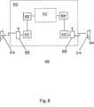
図6はセルラー・ネットワーク602とモバイル端末604とを含む移動通信システム600を示す。セルラー・ネットワーク602はトランスコーダ・ユニット(TRAU)610を介してモバイル・スイッチング・センタ(MSC)608に接続された送受信基地局(BTS)606を備えている。MSCは発呼すべき別のネットワーク612に接続されている。これはセルラー・ネットワーク602の一部でよく、公衆交換電話回線網(PSTN)でもよい。
【0203】
モバイル端末604は各々、モバイル端末604によって送信および受信される双方の信号のノイズを抑制するノイズ・サプレッサ614を備えている。
【0204】
モバイル端末604が発呼するために使用されると、これは、ノイズ・サプレッサ614でノイズ抑制され、音声エンコーダで音声エンコードされ、かつチャネル・エンコーダでチャネル・エンコードされた、ディジタル信号を生成する。エンコードされた信号は次にアップリンク方向にセルラー・ネットワーク602へと送信され、そこで送受信基地局606によって受信された後、トランスコーダ・ユニット610で再びディジタル信号にデコードされ、これは例えばPSTNまたは他のモバイル端末604へと送信されることができる。後者の場合は、信号はダウンリンク方向にトランスコーダ・ユニット610に送信され、そこで再びエンコードされた後、送受信基地局606によって他のモバイル端末604に送信され、そこでデコードされてから、ノイズ・サプレッサ614内でノイズ抑制される。
【0205】
ノイズ・サプレッサはネットワーク内の他のポイントに備えてもよい。例えば、デコードされた後の信号、またはデコードされる前の信号に作用するように、トランスコーダ・ユニット610と連係して備えることができる。このようにしてノイズ・サプレッサをネットワーク602内に設置することに加えて、本発明の別の特徴をネットワークに備えてもよい。例えば、トランスコーダ・ユニット610にDTXおよびBFI表示を備えてもよい。前述のようにこれらは、ノイズ抑制を制御するためにネットワーク・ノイズ・サプレッサによって利用されることができる。更に、トランスコーダ・ユニット610は本発明の以下の特徴を組入れている。すなわち、
先行の欠陥フレーム・ハンドリング・ユニットにおいて、反復され減衰されたフレームに置き換えられた損失フレームに起因するギャップを検出し、これを埋める検出器と、
タンデム接続の配慮に対応するためにノイズ抑制を制御する制御機能と、である。
【0206】
しかし、検出器および/または制御機能であるこのような本発明の特徴を、特にダウンリンク信号に対応するために、トランスコーダ・ユニットにではなく、またはそれに加えてモバイル端末604に備えてもよい。
【0207】
本発明の様々な態様は独立したものであり、かつ独立して動作可能であることに留意されたい。従って、このようないずれか1つまたは複数の態様を、必要に応じてモバイル端末、またはネットワークに組入れてもよい。
【0208】
CDMA音声コーディング基準で採用されているような可変レートの音声コーディックが備えられているダウンリンク接続においてノイズ・サプレッサ44が使用される場合は、付加的な要件に対処する必要がある。遠端(すなわち送信側)での入力信号の特性に従って動作する様々な音声コーディング・ビットレートは、著しく異なる出力音声およびノイズ信号を生成する。その上、出力信号レベルのある程度の減衰は、標準的には最低のビットレートにて適用され、それによって基本的に一種のコンフォート・ノイズと見なすことができる信号を生成する。このように、可変レート音声コーディックと連係したダウンリンク・ノイズ・サプレッサの応用が成功するには下記が必要である。すなわち、
1.利用できる音声コーディングの各ビット・レートに対応する幾つかのバックグラウンド・ノイズ・スペクトル評価を利用すること。
2.利用できる各ビット・レートに連係した、パワー評価の更新と減衰利得計算のための、専用のパラメータのセットを利用すること。
3.利用できるビット・レートと連係した異なる利得計算を利用すること。
4.低いビット・レートでコーディングされた信号に適用される任意のレベルの減衰に関する情報を利用すること。
【0209】
可変レート音声コーディックを使用するシステムでは、ノイズ・サプレッサが効率的に動作するために、音声デコーダによって提供される、使用された音声コーディングのビット・レートに関する情報、を利用することが好適である。
【0210】
本発明の意図は、音声デコーダ用の事後処理段として、必要な時にノイズ抑制を実現可能にすることにある。この目的のため、ノイズ・サプレッサはその状態(DTX)およびチャネル状態に関する音声コーディックからの情報を利用する。
【0211】
これまで本発明の好適な実施形態を図示し、説明してきたが、このような実施形態は例示目的でのみ記載したことが理解されよう。当業者には本発明の範囲から逸脱することなく多くの変化形、変更、および代替で可能である。従って、特許請求の範囲の本発明の趣旨と範囲内のこのような変化形、またはそれと同等の形態を全て包括することを意図するものである。
【図面の簡単な説明】
【図1】 先行技術によるモバイル端末を示す図面である。
【図2】 本発明によるモバイル端末を示す図面である。
【図3】 図2のモバイル端末内のノイズ・サプレッサの詳細を示す図面である。
【図4】 本発明によるウインドウ関数表現を示す図面である。
【図5】 本発明をフローチャートの形式で示す図面である。
【図6】 本発明を組入れた通信システムを示す図面である。[0001]
The present invention relates to a noise suppressor and a noise suppression method. The present invention particularly relates to a mobile terminal equipped with a noise suppressor for suppressing noise in an audio signal. The noise suppressor according to the present invention can be used to suppress acoustic background noise particularly in mobile terminals operating in cellular networks.
[0002]
One of the purposes of suppressing noise in a mobile phone terminal or improving telephone conversation is to reduce the influence of environmental noise on a voice signal and thus improve communication quality. In the case of uplink (transmit, TX) signals, it is also desirable to minimize the negative effects on the voice coding process due to this noise.
[0003]
In face-to-face communication, acoustic background noise interferes with the listener and makes conversation difficult to understand. Ease of understanding is improved when the speaker speaks out louder than background noise. In the case of a telephone, background noise is troublesome because there is no additional information given by expressions or gestures facing the face.
[0004]
In the case of a digital telephone, the voice signal is first converted to a sequence of digital samples by an analog / digital (A / D) converter and then compressed for transmission using a voice codec. The term codec is a term used to describe a pair of encoder / decoders. In this specification, the term “speech encoder” refers to the encoder side of a speech codec, and the term “speech decoder” is used to represent the decoding function of a speech codec. It will be appreciated that a general purpose audio codec may be implemented as a single functional unit, or as separate elements that perform encoding and decoding operations.
[0005]
In the case of digital telephones, the adverse effects of background noise can be significant. The reason is that voice codecs are generally optimized for voice compression and acceptable playback, and if the voice signal is noisy or there is an error in sending or receiving voice, its performance This is because may be damaged. In addition, the presence of noise itself can induce distortion of the background noise signal when it is encoded and transmitted.
[0006]
If the performance of the speech codec is impaired, both the comprehension of the transmitted speech and its subjective quality are reduced. The distortion of the transmitted background noise signal degrades the quality of the transmitted signal, makes it more difficult to hear, and makes it difficult to recognize information in accordance with the situation by changing the nature of the background noise signal. As a result, research in the area of improving speech has focused on investigating the impact of noise on speech codec performance and creating preprocessing methods to reduce the impact of noise on speech codecs.
[0007]
The above problems are associated with configurations where there is only one microphone to provide one signal. In such a configuration, a noise suppressor is provided that can interpret a one-channel signal and determine which part of the signal represents the original speech and which part represents the noise.
[0008]
When a digital mobile terminal receives an encoded audio signal, the signal is decoded by the decoding portion of the terminal's audio codec and sent to a speaker or earpiece for the user of the terminal to listen to. A noise suppressor may be provided after the audio decoder in the audio decoding path to reduce noise components in the received and decoded audio signal. However, under noisy conditions, the performance of the audio decoder is adversely affected, resulting in one or more of the following effects.
[0009]
1. Since the important information required by the audio codec to properly decode the audio signal changes due to the presence of noise, the audio component of the signal may be compromised, i.e., blurred.
2. Since codecs are generally optimized to compress speech rather than noise, background noise may sound unnatural. In general, it increases the periodicity of the background noise component, which can be severe enough to lose contextual information due to the background noise signal.
[0010]
During transmission and reception, information about the encoded audio signal may be lost or corrupted, for example due to transmission channel errors. Such a situation further degrades the output of the audio decoder and causes more artifacts in the decoded audio signal to become apparent. The use of a noise suppressor after an audio decoder in the audio decoding path causes the performance of the audio decoder to be sub-optimal and consequently causes the noise suppressor to not operate optimally.
[0011]
Therefore, special care must be taken when implementing a noise suppressor intended to operate on the decoded audio signal. In particular, the two competing factors must be balanced. If the noise suppressor attenuates the noise too much, sound quality degradation may be caused by the voice codec. However, due to the inherent characteristics of standard audio codecs that are optimized for audio encoding and decoding, the decoded background noise can be harder to hear than the original noise signal, so It is necessary to attenuate as much as possible. Thus, in practice, a slightly lower level of noise reduction has been found to be optimal for decoded audio signals than the level of noise reduction that can be applied to the audio signal prior to encoding. ing.
[0012]
In general, when noise suppression occurs during audio encoding and / or decoding, the background noise level is reduced, audio distortion due to the noise reduction process is minimized, and input background noise is reduced. It is desirable to retain the original properties.
[0013]
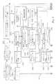
An embodiment of a mobile terminal with a noise suppressor according to the prior art will now be described with reference to FIG. A mobile terminal and a wireless system which is a communication means thereof operate based on the digital cellular phone unified system (GSM) standard. FIG. 1 shows a
[0014]
In the transmission (voice encoding)
[0015]
The improved (noise-suppressed) signal is encoded by
[0016]
A noise suppressor suitable for use in the mobile terminal of FIG. 1 is described in publication WO 97/22116.
[0017]
To extend battery life, mobile communication systems typically employ different types of signal-dependent low power operating modes. Such a mechanism is generally called intermittent voice transmission (DTX). The basic idea of DTX is to interrupt the audio encoding / decoding process during periods of no speech. DTX is also intended to limit the amount of data transmitted over the wireless link during a call pause. Both means are for reducing the amount of power consumed by the transmission apparatus. Typically, a type of comfort noise signal, made similar to background noise at the transmitting terminal, is generated instead of the actual background noise. DTX handlers are well known in the field, such as GSM enhanced full rate (EFR), full rate and half rate speech codecs.
[0018]
Referring back to FIG. 1, the
[0019]
Of all the environments in which mobile phones are used, the worst voice / noise ratios typically occur in moving vehicles. However, if the noise is relatively fixed over a long period of time, that is, if the noise amplitude spectrum does not change much over time, an adaptive filter with an appropriate filtering coefficient is used to remove most of the noise in the vehicle. can do.
[0020]
The noise level in an environment where a mobile terminal is used may change constantly. The frequency component (spectrum) of the noise also changes, and the change may be very significant depending on the environment. In response to such changes, the threshold of the
[0021]
Yet another mechanism is used to ensure that low levels of noise (often not fixed over time) are detected as speech. In this case, an additional fixed threshold is used so that an input frame with a frame power below the threshold is considered a noise frame.
[0022]
The VAD hangover period is used to eliminate mid-level burst clipping of low level speech. To prevent noise spikes from stretching, hangovers are only added to speech bursts that exceed a certain period. The operation of the voice activity detector in this regard is well known in the art.
[0023]
The output of the
[0024]
In most mobile communication systems, DTX is most commonly employed in uplink connections because voice encoding and transmission typically consumes significantly more power than reception and voice decoding, Also, mobile terminals typically rely on limited energy stored in the battery. During periods when signals that are supposed to be accompanied by speech are not being transmitted, comfort noise is generated to give the listener an in-region as if the signal was actually continuous. As will be described in detail below, some mobile phone systems generate comfort noise at the receiving terminal based on the information received from the transmitting terminal and describing the noise characteristics at the transmitting terminal. is there.
[0025]
Generally, an explicit flag indicating whether or not the DXT operation mode is set is provided in the audio decoder. This applies, for example, to all GSM audio codecs. However, frame repeat mode must be activated in the noise suppressor, for example by comparing the input frame with the previous frame and setting up the voice activated switch (VOX) flag if the consecutive frames are identical. There are other cases such as personal digital cellular (PDC) networks that must be done. In addition, when connecting between mobiles, the downlink connection is not provided with information regarding the presence of DTX in the uplink connection.
[0026]
In some speech codecs, such as the GSM EFR codec, a decision is made to disconnect transmissions during speech pauses in the speech encoder's DTX handler. At the end of the speech burst, the DTX handler uses a small number of consecutive frames to generate a silence descriptor (SID) frame, which conveys a comfort noise parameter that indicates the estimated background noise characteristics to the decoder. Used for. A silence descriptor (SID) frame is characterized by a SID codeword.
[0027]
After the transmission of the SID frame, the wireless transmission is blocked and the voice flag (SP flag) is set to zero. Otherwise, the SP flag is set to 1 to indicate wireless transmission. The SID frame is received by the speech decoder, which then generates noise having a spectral profile that corresponds to the characteristics described in the SID frame. Occasional SID frame updates are sent to the decoder to maintain the correlation between background noise at the sending terminal and comfort noise generated at the receiving terminal. For example, in the GSM system, a new SID frame is transmitted every 24 frames of regular communication. This occasional update of the SID frame not only allows for acceptable and accurate comfort noise generation, but also greatly reduces the amount of information that must be transmitted over the wireless link. As a result, the bandwidth required for transmission is reduced, which helps to effectively use radio resources.
[0028]
In the reception (audio decoding)
[0029]
The mobile terminal further comprises a defective
[0030]
An example of a prior art defective
[0031]
The purpose of frame replacement is to conceal the effects of lost frames. The purpose of attenuating the output when several frames are lost is to indicate to the user that the radio link (channel) may have broken down and unpleasant sound that may result from the frame replacement procedure This is to avoid the possibility of the occurrence of. However, replacing and attenuating background noise in lost frames that are usually not informative can affect the perceived quality of noisy speech or pure background noise. Even in the case of background noise at a slightly lower level, abruptly attenuating the background noise in a lost frame gives the impression that the smoothness of the transmitted signal is degraded. Such an impression becomes stronger as the background noise increases.
[0032]
Whether it is decoded speech, comfort noise, or repeated, attenuated frames, the signal generated by the speech decoder is converted from digital to analog format by the digital /
[0033]
According to one aspect of the present invention, a noise suppressor is provided for suppressing noise in a signal including background noise, the suppressor comprising an estimator for evaluating a background noise spectrum. Thus, the evaluation of the background noise spectrum is controlled using an indication from at least one of the intermittent transmission unit and the channel error detector.
[0034]
Preferably, the indication is made by a voice decoder in the uplink path in the network.
[0035]
Preferably, the noise suppressor suppresses noise in the signal supplied by the audio decoder.
[0036]
Preferably, the display appears at the channel decoder and is processed by the audio decoder. Preferably, the display is processed by a defective frame handling unit in the audio decoder.
[0037]
Preferably, the noise suppressor sends a noise suppressed signal to the speech encoder.
[0038]
Preferably, the noise suppressor utilizes a flag or indication indicating that an error has occurred in each frame used to transmit a signal through the channel.
[0039]
Preferably, the update of the estimated background noise spectrum is paused during the period when channel errors in the signal are detected by the channel error detector. Thus, the portion of the signal that contains channel error or the portion of the signal that is generated to mask or mitigate the channel error is not utilized for noise evaluation.
[0040]
Preferably, the noise suppressor comprises a voice activity detector for controlling the evaluation of the background noise spectrum. Preferably, the estimated background noise spectrum is updated when the voice activity detector indicates that no speech is present. Preferably, when the channel error detector detects a channel error, the state of the voice activity detector and / or the state of the previous silent / voice decision memory of the detector is frozen.
[0041]
Preferably, comfort noise is generated by the comfort noise generator during periods when no signal is being transmitted. During the period when the intermittent audio transmission unit indicates that no signal is being transmitted, the update of the evaluated background noise spectrum is suspended. Thus, comfort noise is not used for noise evaluation.
[0042]
The term “comfort noise” refers to noise that is generated to represent background noise as if the background noise did not actually occur when the comfort noise was generated. For example, comfort noise may be noise that was evaluated by background noise analysis before it was generated, random or pseudo-random noise, or evaluated by background noise analysis. A combination of generated noise and random or pseudo-random noise may be used.
[0043]
In the embodiment of the present invention in which the mobile terminal is provided with a noise suppressor, the noise suppressor may be mounted so that the noise-suppressed voice is supplied to the encoder and the noise-suppressed voice is received from the decoder. Of course, the encoder and decoder may be codecs.
[0044]
Preferably, the noise suppressor is in the radio path. The noise suppressor may be in a downlink radio path from the communication network to the communication terminal.
[0045]
In another aspect of the invention,
Evaluating a background noise spectrum;
Using the background noise spectrum to suppress noise in the signal;
Receiving an indication representing the operation of at least one of an intermittent voice transmission unit and a channel error detector;
There is provided a noise suppression method for suppressing noise in a signal including background noise, including using the display to control evaluation of a spectrum of background noise.
[0046]
In another aspect of the present invention, a noise suppressor is provided that suppresses noise in a signal including background noise, the noise suppressor including an estimator for evaluating a background noise spectrum. A mobile terminal is provided in which the display from at least one of the transmission unit and the channel error detector is utilized to control the evaluation of the background noise spectrum.
[0047]
Preferably, the mobile terminal comprises a channel error detector. The channel error detector may indicate that there is an error in the individual frame used to transmit the signal through the channel.
[0048]
Preferably, the display is performed by a voice decoder in the downlink path. Preferably, the detector for detecting channel errors is in the audio decoder. Preferably, the display appears in the channel decoder and is processed by the audio decoder. Preferably, the display is processed by a defective frame handling unit in the audio decoder.
[0049]
Preferably, the mobile terminal noise suppressor comprises a voice activity detector for controlling the evaluation of the background noise spectrum. Preferably, the voice activity detector is part of a speech encoder.
Preferably, the mobile terminal comprises an intermittent transmission unit.
[0050]
In another aspect of the present invention, a downlink path comprising a receiver for receiving a radio signal and means for outputting the signal in a form understandable to a user, and noise in the received signal provided in the downlink path A mobile terminal including a noise suppressor that suppresses noise is provided.
[0051]
The term downlink refers to a path from a network to a mobile terminal when used in a communication path in a communication system. Of course, the signal may be transmitted not to the mobile terminal but to a fixed communication terminal such as a wired telephone.
[0052]
In another aspect of the present invention, there is provided a mobile communication system including a mobile communication network and a plurality of mobile communication terminals, the network including a noise signal for suppressing noise in a signal including background noise. The noise suppressor includes an estimator for evaluating a background noise spectrum, and uses a display from at least one of the intermittent transmission unit and the channel error detector to A mobile communication system is provided in which the evaluation of the spectrum of noise is controlled.
[0053]
Preferably, the signal is generated by a microphone. This may be generated by a telephone microphone.
[0054]
Preferably, the mobile communication system includes an intermittent transmission unit.
[0055]
Preferably, a noise suppressor is mounted at the output of a decoder in the network to suppress noise in the decoded speech. Alternatively, the noise suppressor sends the noise-suppressed voice to the encoder in the network.
[0056]
In yet another aspect of the present invention, a mobile communication system comprising a mobile communication network and a plurality of mobile communication terminals, wherein the network is configured to suppress noise in a signal sent by at least one mobile terminal. A mobile communication system provided with a noise suppressor is provided.
[0057]
In another aspect of the invention, a frame replacer for replacing a frame in the signal to limit failures due to channel errors in the signal, indicating that it has been previously received and is free of errors. A memory for storing the received signal portion, a noise generator for generating a noise signal, a previously received signal portion that has been received and attenuated, and a noise signal. And a frame generator that generates a combined signal, the frame generator increasing the contribution from the noise signal to the combined signal over time compared to a previously received signal portion. A frame replacer is provided.
[0058]
The noise signal may be a random or pseudo-random signal. The noise signal may be a combination of a random or pseudo-random signal and noise evaluation.
[0059]
Preferably, the previously received signal portion is repeated and gradually attenuated with each iteration. This may be a frame that has already been received. The noise signal may be a set of generated composite frames. The synthesized frame of the noise signal may be added frame by frame to each gradually attenuated frame of the previously received signal portion. Preferably, the contribution of the noise signal increases to the same extent as the previously received signal portion is reduced, and the level of the combined signal is approximately the same as the level of the previously received signal.
[0060]
To indicate a breakdown of the channel, at least one of the noise signal and the previously received signal portion is attenuated. Preferably both signals are attenuated. The attenuation of the noise signal may be initiated after the previously received signal portion has been attenuated to the extent that it no longer contributes to the combined signal.
[0061]
The frame replacer may be part of a defective frame handler that forms part of the audio decoder. The noise generator may be provided in the noise suppressor. The noise suppressor gets the information from the audio decoder, and the received information and a unique measure of how much the repeated / extrapolated frame has been attenuated since the last time the display of the defective frame was turned off, Based on, the amplification it adds to the generated noise can be adjusted.
[0062]
The replacer can replace frames with errors, lost frames, or both. Channel errors can also be caused by transmission of signals over the air interface.
[0063]
In another aspect of the invention, a method for replacing a frame in a signal to limit a failure due to a channel error, comprising:
Storing a previously received signal portion, indicating that there are no errors, and
Gradually attenuating a previously received signal portion;
Generating a noise signal;
Generating a combined signal combining a previously received signal portion and a noise signal;
Over time, increasing the contribution from the noise signal to the combined signal as compared to a previously received signal portion.
[0064]
In another aspect of the present invention, a mobile terminal comprising a frame replacer for replacing a frame in a signal in order to limit a failure due to a channel error in the signal, the frame replacer comprising: A memory for storing previously received signal parts that are displayed as error free, a noise generator that generates a noise signal, and a previously received signal part that is gradually reduced and attenuated. And a frame generator that generates a combined signal combining the noise signal, the frame generator over time with respect to the combined signal compared to the previously received signal portion. A mobile terminal is provided that increases the contribution from noise signals.
[0065]
In another aspect of the present invention, there is provided a communication system including a communication network having a frame replacer for replacing a frame in a signal and a plurality of communication terminals in order to limit a failure caused by a channel error. The frame replacer gradually reduces a previously received signal portion, a memory for storing a signal portion that was previously received and displayed as error free, a noise generator that generates a noise signal, and And a frame generator that generates a combined signal combining the previously received and attenuated signal portion and the noise signal, the frame generator over time and the previously received signal portion; In comparison, a communication system is provided that increases the contribution from the noise signal to the combined signal.
[0066]
In another aspect of the present invention, a detector comprising a frame sequence for detecting signal impairments including background noise, wherein the amplitude of the signal is measured to detect a sudden drop in amplitude. If a drop in amplitude is detected, the abruptness is determined, and if the abruptness is severe enough, a detector is provided that displays intermittency to control the background noise assessment. The
[0067]
In another aspect of the present invention, a noise suppressor is composed of a frame sequence, and an estimator for evaluating background noise of a signal including background noise, and for detecting a sudden drop in amplitude. When the amplitude of the signal is measured and a decrease in amplitude is detected, its abruptness is determined, and if the abruptness is sufficiently severe, an intermittent indication is displayed to control the background noise evaluation. A noise suppressor is provided that includes a detector for detecting intermittency in the signal that is made.
[0068]
The present invention detects artificial gaps in a signal that can be intentionally generated but cannot be easily detected due to the lack of intermittency in the sequence of frames.
[0069]
Preferably, the frequency of updating the background noise assessment is controlled using an intermittent display. Preferably, the frequency is reduced when a decrease in amplitude is detected.
[0070]
Preferably, it is not concurrent noise that reduces the frequency with which the background noise rating is updated, but the background noise rating is updated by something that is based on previous noise. This is to prevent this. Preferably, the background noise estimate is generated with a noise suppressor. The detector may be part of the noise suppressor, but may simply be a separate unit that passes input to or from the noise suppressor. The amplitude reduction may be due to one or more lost frames, or may be due to attenuation used to mask such lost frames, or an iterative process, or occur simultaneously. It may be due to a reduction in the actual noise contained in the signal. Alternatively, the detector detects intermittency due to microphone muting. Decreasing the update frequency of the noise evaluation results in less influence of the noise evaluation on the signal portion being processed at that particular time. In this way, if the actual background noise is still included in the signal, but the effect is reduced, the actual background noise is not included in the signal at that time, In order to address the possibility of using other signals instead, such as repeated frames or attenuated frames instead, noise estimation is still performed based on actual background noise.
[0071]
In another aspect of the present invention, a method for detecting intermittency in a signal comprising a frame sequence and including background noise, comprising:
Measuring the amplitude of the signal to detect a sudden decrease in amplitude;
Detecting a decrease in amplitude;
Determining the degree of abrupt reduction;
If the abruptness is severe enough, a method is provided that includes an intermittent display to control the background noise assessment.
[0072]
In another aspect of the present invention, a mobile terminal having a noise suppressor, the noise suppressor, an estimator for evaluating background noise in a signal consisting of a frame sequence, and an abrupt amplitude To detect the drop, the amplitude of the signal is measured, and if a drop in amplitude is detected, its abruptness is determined, and if that abruptness is severe enough to control the background noise assessment There is provided a mobile terminal including a detector for detecting intermittency in a signal on which intermittency is displayed.
[0073]
In another aspect of the present invention, a communication system comprising a communication network having a noise suppressor and a plurality of communication terminals, the estimator for evaluating background noise in a signal comprising a frame sequence Then, the amplitude of the signal is measured to detect a sudden drop in amplitude, and when a drop in amplitude is detected, the degree of abruptness is determined. There is provided a communication system comprising a detector for detecting intermittency in a signal, wherein intermittency is displayed to control evaluation.
[0074]
In another aspect of the invention, a noise suppression stage acting on the signal, the first windowing block for weighting the signal with a first window function, and converting the signal from the time domain to the frequency domain And a noise suppression stage comprising a transformer for converting a signal from the frequency domain into a time domain, and a second windowing block for weighting the signal with a second window function.
[0075]
In another aspect of the invention, a two-stage windowing method comprising:
Weighting signals in the time domain with a first window function to create a frame;
Transforming the frame into the frequency domain;
Inverse transforming the frame into the time domain;
Weighting the frames with a second window function to suppress errors that match between adjacent frames.
[0076]
Preferably, the above method includes a window weighting step after the audio encoding step. Alternatively, the weighting may be performed before the speech encoding step.
[0077]
Preferably, the window function has a trapezoidal shape with a slope and a slope. Preferably, the first window function has a front slope having a slope that is shallower than the slope of the front slope of the second window function. Preferably, the first window function has a rear slope having a gentler slope than that of the second window function. Since the gradient of the first window function is relatively gentle, a favorable frequency conversion can be performed. Due to the relatively steep slope of the second window function, mismatch between adjacent frames in the time domain is well suppressed.
[0078]
In another aspect of the invention, a mobile terminal comprising a noise suppression stage acting on a signal, the noise suppression stage comprising: a first windowing block that weights the signal with a first window function; Provided by a mobile terminal comprising a transformer for converting a signal into the frequency domain, a transformer for converting a signal from the frequency domain into the time domain, and a second windowing block for weighting the signal with a second window function Is done.
[0079]
In another aspect of the present invention, a communication system comprising a noise suppression stage acting on a signal and a communication network comprising a plurality of communication terminals, wherein the noise suppression stage weights the signal with a first window function. A first windowing block, a transformer for converting a signal from the time domain into the frequency domain, a noise suppressor for suppressing noise in the signal, and a transformer for converting the signal from the frequency domain into the time domain; A communication system is provided comprising a second windowing block that weights the signal with a second window function.
[0080]
The sound is not always present, but the signal may be a noise sound.
Embodiments of the present invention will now be described by way of example only with reference to the accompanying drawings.
[0081]
FIG. 1 has already been described in connection with conventional noise suppression techniques known in the art.
[0082]
FIG. 2 shows a
[0083]
The
[0084]
Although the
[0085]
FIG. 3 shows details of the
[0086]
In the uplink (voice encoding) branch, the A /
[0087]
At
[0088]
At
[0089]
In
[0090]
It is known that the load and memory requirements for computation and the algorithmic delay of windowing operations can be reduced by a simple trapezoidal window function with short overlapping segments. However, using such a simple window function may have an adverse effect on the output signal. The most important of these effects is bee noise induced at the short, overlapping frame boundaries (eg, within signal levels and spectral content) due to mismatches. This artifact may occur under moderate input SNR conditions where the gain function exhibits an attenuation gain that varies greatly between the calculated frequency bands. If the noise suppressor operates as a pre-processing stage before the speech encoder, for example in the uplink (speech encoding) branch, the bee noise is generally masked by the speech coding-decoding process itself.
[0091]
However, in the case of the
[0092]
Thus, in accordance with the present invention, an output time domain frame is formed by an overlap addition procedure that is improved to suppress frame boundary area artifacts. This is represented by window functions W1 and W2. A “two-stage” windowing configuration is applied in which a combination of at least two trapezoidal window functions with slightly different characteristics is used. One window function is for a windowing frame input to the FFT, and the other window function is for a windowing frame output from the IFFT. In the method of the present invention, a first trapezoidal
[0093]
W2 is 86 samples long with a forward slope and back slope function, 6 samples long. The beginning of this second window is synchronized with the sixth sample (vector) of the IFFT output sequence, and the slope function is a slope function that produces a linear slope that is 6 samples long at both ends of the window. The output from this operation is a vector of 86 samples, of which the first 6 samples are the same size samples and samples from the output
[0094]
The two-stage trapezoidal windowing process described above may be used in conjunction with a noise suppressor used as a post-processing stage after speech decoding or as a pre-processor prior to speech encoding Note that it may apply to noise suppressors. In particular, the improved quality provided by the two-stage window at the input of the speech encoder can enhance the quality achieved in the speech encoding process.
[0095]
Since the input vector for FFT actually consists of real numbers, triangular recombination as described in Numerical Recipes (Numerical Computation) C The Art of scientific Computing (pages 414-415, 1988) The computational load can be reduced by packing two input frames into one complex FFT using a trigonometric recombination method. In this approach, the windowed, zero-padded first frame samples are assigned to the real component of the input sequence for FFT. The second frame is assigned to the imaginary component of the input sequence. Next, a 128-point complex FFT is calculated. The complex spectrum of the two frames can be separated by triangular recombination. After noise reduction processing of the two complex spectra, they are synthesized by adding the second spectrum multiplied by the imaginary unit to the first spectrum. The resulting complex spectrum is sent to the IFFT, and the output time domain frame can be found in the real and imaginary parts of the IFFT output.
[0096]
An approximate amplitude spectrum is calculated from the complex FFT at
[0097]
The background noise spectrum estimate is based on the approximate amplitude spectrum representation obtained as the output of
[0098]
In a preferred embodiment of the present invention, the frequency range from 0 Hz to 4 kHz is divided into 12 calculated frequency bands of unequal width. This division is based on statistical knowledge about the average position of the formant frequency in the speech. The process of averaging spectral values over the computational frequency band effectively reduces the number of spectral bins to be processed, and thus reduces the computational load of the algorithm, resulting in savings in both static and dynamic RAM. Bring. In addition, the averaging in the frequency domain has the effect of smoothing the improved speech. However, since these advantages are obtained at the expense of frequency resolution, a compromise is necessary. In particular, if the background noise is in the same frequency range as the audio signal, the frequency resolution must be high enough to separate the audio and noise.
[0099]
Here, the operation of the noise suppression process performed in the
[0100]
Within the
[0101]
The gain calculation formula for Wiener amplitude evaluation for an arbitrary frequency bin θ is expressed as follows.
[0102]
[Expression 1]
[Expression 2]
[0103]
The correction of the Wiener filtering introduced here includes a method in which the prior SNR for each calculation frequency band is evaluated. Since the original audio signal and the noise signal itself are not known in advance, there is basically no way to extract the true prior SNR from the single channel signal.
[0104]
Prior SNR evaluation is performed at
[0105]
[Equation 3]
In Equation 3, γ (s, n) is the number of frames calculated at
[0107]
The prior SNR can be accurately evaluated under conditions where the SNR is high, more generally in a frequency band where speech is clearly present or not present at all. However, the Wiener evaluation equation shown in
[0108]
In the present invention, instead of the above-described conventional speech / noise ratio, the prior ratio of speech including noise and noise is evaluated. In the following description, the ratio of speech including noise to noise is indicated using the abbreviation NSNR. By using a prior NSNR assessment rather than a simple out-of-the-box assessment of prior SNR, the subjective (perceived) quality of a noise-suppressed speech signal is significantly increased.
[0109]
Thus, based on the present invention, the evaluation of the voice / noise ratio including noise, NSNR, is used instead of the evaluation of the prior SNR, and the following formula in place of Equation 3 is obtained.
[0110]
[Expression 4]
We argue that NSNR can be evaluated more accurately than prior speech / noise ratio, SNR. Based on Equation 4, the posterior SNR value obtained for the previous frame and multiplied by the respective gain factor of the previous frame is used to calculate the speech / noise ratio including the prior noise for the current frame. The a posteriori SNR value for each frame is stored in the
[0112]
In accordance with the present invention, the NSNR estimate given by Equation 4 is also constrained by the following, as shown in Equation 5. This effectively sets an upper limit on the maximum noise attenuation that can be obtained.
[0113]
[Equation 5]
Threshold value ξ producing a maximum attenuation of about 10 dBBy selecting min and substituting the above ξ (s) with a hat into the Wiener gain equation, the residual background noise (which is the noise component remaining after noise suppression) is smoothed, and the speech distortion is significant. Reduce.
[0115]
The forgetting factor α in Equation 4 is also processed differently than the prior art noise suppression scheme. Instead of selecting the forgetting factor α based on the VAD determination, this is determined based on the current SNR condition. This feature is triggered by the fact that under low SNR conditions, the time domain smoothing of the prior NSNR evaluation can mitigate the negative effects of evaluation errors on the quality of noise-suppressed speech. . In order to establish the relationship between the forgetting factor and the current SNR condition, the inverted posterior SNR display shown in Equation 6 below, snrapIn , Α is calculated based on.
[0116]
[Formula 6]
[0117]
To obtain a speech level estimate, the power spectrum of the current speech frame is averaged over the calculated frequency band. The frame power is filtered with a variable forgetting factor and a variable frame delay to evaluate the speech level including noise. The noise level estimate is obtained by averaging the background noise spectrum estimate over the calculated frequency band and filtering with a fixed forgetting factor over time.
[0118]
The
[0119]
Updates are allowed depending on whether
[0120]
To favor an update with frame power representing the average range of noisy voice power, if the difference between the current frame power and the previous voice level estimate is a small, absolute term, The forgetting factor takes a value that enables the fastest update.
[0121]
The noise level estimate is obtained by filtering the total power in the background noise spectrum estimate for each frame. In this case, no additional conditions in accordance with VAD are set, and the update procedure of the noise spectrum evaluation is already sufficiently reliable, so that the forgetting factor is kept constant.
[0122]
Finally, a relative noise level indicator is defined that is used as an SNR correction coefficient. This is defined as the scaled and limited ratio between the noise level estimate and the noisy speech level estimate, as shown in Equation 7 below.
[0123]
[Expression 7]
[0124]
The noise level estimate (N with hat) is set to zero at startup. The above-mentioned voice level evaluation including noise (S with hat) is initially set to a value corresponding to a moderately low voice power. In the subsequent processing, another slightly smaller value is used as the minimum value for evaluating the voice level including noise.
[0125]
The SNR correction is applied to the prior NSNR evaluation according to Equation 8.
[Equation 8]
This gives a modified prior NSNR assessment that is substituted into Equation 2.
[0127]
Detection of voice activity in a given voice frame is based on the a posteriori SNR estimate calculated in
[0128]
[Equation 9]
[0129]
DSNR Exceeds the threshold vth, the frame is interpreted as containing speech, and the VAD function indicates “1”. Otherwise, the frame is classified as noise and VAD indicates “0”. These binary VAD decisions are stored in a shift register over 16 frames (one 16-bit static variable) so that past VAD decisions can be referenced.
[0130]
The VAD threshold vth is usually constant. However, if the SNR condition is very good, the threshold is incremented to prevent small variations in signal power from being considered speech. Small values of the relative noise level η (described above) indicate good SNR conditions. This is because the factor is a scaled ratio of the estimated noise power to the speech power containing the estimated noise. Thus, when η is small, the VAD threshold vht increases linearly with respect to the negative number of η. The threshold for η is also defined so that vht is kept constant if η is greater than the threshold.
[0131]
If the input signal power is very low, as described above, small non-fixed events in the signal even after adaptation to the VAD threshold may be mistakenly considered to be speech. In order to suppress such erroneous detection of speech, the total power of the input signal frame is compared with a threshold value. If the frame power remains below the threshold, the VAD decision is forced to “0” to indicate no speech. However, this modification is only performed when the VAD decision is applied to the prior NSNR to determine the weight of the previous evaluation and the posterior SNR of the new frame in Equation 4. For the purpose of updating the background noise spectrum evaluation and the noisy speech and noise level evaluation, and in a minimal gain search (described below), an invariant VAD decision in the 16-bit shift register is Used.
[0132]
In order to ensure a good response to transitions in speech, the noise attenuation gain factor calculated in
[0133]
As the spectral resolution of the gain factor vector increases, the average of the power spectral components also decreases, i.e., the number of FFT bins per calculated frequency band is reduced, which may lead to inconvenient variations in residual noise. Will increase. However, if the calculation frequency band is widened, the ability of the algorithm to find the frequency at which noise is concentrated decreases. This can cause undesirable fluctuations in the output of the noise suppressor, especially at low frequencies where noise is generally concentrated. In addition, a high proportion of low frequency content in the audio tends to reduce noise attenuation in the same low frequency range within the frame containing the audio, resulting in undesirable modulation of residual noise that is synchronized with the rhythm of the audio. .
[0134]
In accordance with the present invention, the problems outlined above are addressed using a “minimum gain search”. This is performed at
[0135]
[Expression 10]
[0136]
The minimum gain search tends to smooth and stabilize the function of the noise suppression algorithm. As a result, the residual background noise resonates more smoothly and non-stationary background noise components that change rapidly are attenuated efficiently.
[0137]
As already explained, when applying noise suppression in the frequency domain, it is necessary to obtain an evaluation of the background noise spectrum. This evaluation process will now be described in more detail. According to the present invention, the background noise spectrum estimate is obtained by averaging the frequency spectrum of the input signal frame during periods of no voice activity. This is done in a
[0138]
[Expression 11]
[0139]
The forgetting element is configured to efficiently deal with the update of noise statistics given by Equation 11 using the amplitude spectrum. For upward updates, a relatively fast time constant is used with a smaller forgetting factor in the amplitude domain, and a slower time constant is used for downward updates. The time constant is also changed to accommodate large and small changes. If the spectral component has to be updated with a value that is significantly larger than the previous assessment, an abrupt update is made in the upward direction, and if the new spectral component is significantly smaller than the previous assessment, A gradual update is performed in the downward direction. On the other hand, a slightly slower time constant is used to update the spectral component values close to the previous evaluation.
[0140]
Since
[0141]
As detailed below, this problem is addressed by shielding the decision window from the
[0142]
According to the present invention, the background noise spectrum evaluation is updated in two stages. Initially, an interim power spectrum estimate is made at
[0143]
1. The
2. It is determined that the signal is stationary for the required number of frames.
3. The power spectrum of the current frame is lower than the background noise spectrum estimate in any frequency band.
[0144]
Second, the provisional that occurred (from block 332) unless the VAD decision in the subsequent frame is “1” and the previous (ie, immediately preceding) three frames produce a VAD decision “0”. The power spectrum estimate is used as the actual background noise spectrum estimate for subsequent frames. In such a case, correspondingly, for example at the start of speech, the previous background noise spectrum estimate is copied from
[0145]
Although the background noise spectrum evaluation process is controlled by the
[0146]
To address this problem, a recovery method is used. During the period that
[0147]
To determine if the current frame presents a fixed signal, a short-term summation of the amplitude spectrum of the input signal is stored in
[0148]
In addition to the basic update approach and repair method based on VAD described above, if the corresponding component of the amplitude spectrum of the current frame is smaller than the current background noise spectrum estimate, the back-up in all frames The ground noise spectrum evaluation component is updated. This allows (1) a large initial value of background noise spectral components (discussed below) and (2) quick recovery from false forced updates that may occur during the actual speech frame. This additional update format, referred to as “down-up-dating”, is based on the fact that noise itself has never higher amplitude than noise, plus speech. Down-update is done by updating the provisional background noise spectrum estimate at
[0149]
At startup, the background noise spectrum evaluation component in
[0150]
The operation of the
[0151]
During periods when no frames are received, no speech or noise is received, so the provisional background noise spectrum estimate at
[0152]
In addition, error speech frames that fail to detect errors cause the
[0153]
A related problem is induced by using any similar function, such as intermittent transmission (DTX) or voice operated switching (VOX). As described above, during DTX, a comfort noise spectrum is generated and the comfort noise is reproduced instead of the true noise. If the spectrum of the comfort noise is different from the true noise spectrum, for example, if the true noise spectrum has changed during comfort noise playback, the background noise spectrum evaluation at
[0154]
To address such issues due to defective speech frames and DXT effects, these effects are also updated in the long-term evaluation of noisy speech levels, or in the
[0155]
Embodiments of the present invention provide a mobile phone having a noise suppressor located on both the uplink and downlink channels. In a communication system in which two such mobile phones communicate, the signal passes through a number of cascaded noise suppressors. In addition, if noise suppressors are also used in cellular networks such as switches, transcoders, or other network devices, there are more noise suppressors in the cascade. Such noise suppressors are generally individually optimized to maximally attenuate noise without inducing distorting distortion in the speech. However, when two or more noise suppression operations are used in such a cascade, audio distortion is induced.
[0156]
In one embodiment of the present invention, the
[0157]
The control variable for signal-dependent gain control evaluates the effective full-band posterior SNR of the noise suppressor input signal as a ratio of long-term evaluation of noisy speech power and background noise power Is set. The full band prior SNR is calculated at
[0158]
Posterior SNR, ie snrapAs described above, i is calculated as the ratio of noise and the level evaluation of speech including noise, and the ratio between N with a hat and S with a hat. In this case, the ratio between the noise level and the level of the speech including noise is not scaled as in the case of the calculation of the SNR correction coefficient (Equation 7), and is low-pass filtered over the entire speech frame. The purpose of filtering is to mitigate the effects of sudden changes in the level of speech or background noise in order to smooth the attenuation control. Control variable snrapThe evaluation of i is expressed as follows.
[0159]
[Expression 12]
[0160]
A control mechanism for limiting noise attenuation in good SNR conditions has been devised such that attenuation in decibels (dB) decreases linearly with increasing SNR in decibels. This calculation method is intended for smooth transitions that cannot be perceived by the listener. Moreover, control is limited to a limited input SNR range.
[0161]
Attenuation reduction is achieved by underestimating the Wiener gain-type background noise spectrum term. Instead of Equation 2, a modified gain calculation formula is used.
[0162]
[Formula 13]
Control variable snrapunity term for i u (snrapThe dependence of i) can be found by expressing the proportionality in dB scale at maximum attenuation. Next, the following relational expression can be derived.
[0164]
[Expression 14]
[0165]
In order to accommodate two competing gain control mechanisms and avoid suboptimal attenuation that occurs under certain conditions, the control parameters of gain control, and in particular the control variables and maximum attenuation range, are within the range where maximum benefits are expected. Carefully selected for best noise suppression. This is due to a sufficiently good evaluation of the SNR state.
[0166]
The first (uplink) noise suppressor is typically the input of the second (downlink) noise suppressor, although problems are anticipated when combining the gain function on the one and the other on the downlink. Improve the SNR state at. Therefore, the above must be taken into account in the tandem connection so that a smooth and basically monotonically synthesized gain function is obtained.
[0167]
The
[0168]
Defective frame indication flags derived from the
[0169]
Immediately after a lost speech frame burst is detected, certain functions that are normally controlled by the
[0170]
In order to maintain the proper spectral level and shape of the background noise spectrum evaluation, the evaluation is not updated while the defect frame display flag is set. In particular, the provisional background noise spectrum evaluation is not updated. However, as described above, when the determination of the
[0171]
If the defective frame is flagged for proper reference to the fixity detection at
[0172]
In order to achieve proper background noise reduction with repeated and attenuated frames, the attenuation performed on the signal decoded by the defective frame handler must be taken into account. To that end, the background noise spectrum evaluation (used to generate the a posteriori SNR by dividing the power spectrum of the current frame by component) has an iterative frame attenuation gain. Is multiplied. The iterative frame attenuation gain is calculated at
[0173]
The noisy speech level estimate (S with hat) calculated at
[0174]
In contrast, the noise level estimate N is continuously updated at
[0175]
The minimum gain search is disabled during the defective frame. Otherwise, an update of the gain memory with a reduced gain value, for example, biases the transition from a defective frame to a good speech frame, so that the first few (eg one Or two) good speech frames are over-damped.
[0176]
In a faulty channel error condition, the faulty error frame is postponed to the audio decoder because the
[0177]
If the burst period of a high-power defective frame that is not detected is long (for example, its duration is 0.5 seconds or more), there is a risk that a forced update of the background noise spectrum evaluation is triggered. This requires a fixed degree of input, but this condition will be met if the decoded error frame is similar to white noise. However, since such long-term error bursts are already undergoing call dropping, the worst case of initiating such a forced update would be unlikely. Moreover, even if the background noise spectrum estimate is updated to a high level by an error frame,
[0178]
In accordance with the present invention, measures are taken in the noise suppressor to address problems that can occur when connecting mobiles that are prone to defective channel conditions in either of two radio paths.
[0179]
To address this issue, the
1. Comparing the input power within each calculated frequency band to a small threshold;
2. Comparing the updated input power to the current rating level within each calculated frequency band; and
3. Comparing the fixity measure to the fixity threshold calculated at
[0180]
The first two steps described above are performed for each calculated frequency band. The purpose of the third comparison step is to disable the repair operation in the low noise state. If the noise is at a low level from the beginning of the call, the short-term average of the input amplitude spectrum will never be at a high level, so that the fixedness measure remains at a low level. In contrast, if the noise level drops after being high, the short-term average of the input amplitude spectrum will be lower during the slow update, so this procedure will restore normal update speed after a while. To do.
[0181]
In the case of noisy speech level evaluation, only the first two comparisons above are performed and they are performed at the effective full band power.
[0182]
Even if a lost frame is reliably detected by the
[0183]
This approach for detecting undetected muted frames and protecting against the undetected muted frames can identify frames with little or no signal loss. Furthermore, these techniques do not adversely affect the absence of signal gaps.
[0184]
As described above, the DTX handler operates in conjunction with the audio decoder. The
[0185]
In the present GSM system, a clear flag indicating whether or not the DTX operation mode is on is set in the audio decoder. In the GSM voice codec, the decision to switch off transmission during speech interruption is made by the voice codec transmission (TX) intermittent transmission (DTX) handler. At the end of a speech burst, it captures a number of consecutive frames to generate a new SID frame, which then transmits a comfort noise parameter describing the estimated background noise characteristics to the decoder To be used. After transmission of the SID frame, wireless transmission is blocked and the voice flag (SP flag) is set to zero. Otherwise, the SP flag is set to 1 to indicate wireless transmission.
[0186]
This audio flag is received by the audio decoder and is used by the
[0187]
The ability of the GSM speech codec DTX serves to evaluate the level and shape of the background noise spectrum as the process changes. In addition, the spectrum shape of comfort noise is usually flatter than the spectrum of actual background noise. Accordingly, the
[0188]
The update of the background noise spectrum estimate at
[0189]
In a comfort noise frame, the noise attenuation gain is assigned the minimum value allowed within all calculated frequency bands. This minimum gain value is determined by substituting ξ (S) with a hat for ξ in Equation 8 and substituting the result into Equation 2. Because this special gain formula is used, the pre-SNR in
[0190]
In one embodiment of the present invention, the
[0191]
Due to the smooth nature of the comfort noise generated in the speech decoder, it is not necessary to use the minimum gain search function by
[0192]
In all current GSM speech codecs, the speech decoder is provided with an explicit flag that indicates whether the DTX mode of operation is on. For other systems, such as PDC systems that do not have such an explicit flag, compare the input frame to the previous frame and set up the VOX flag if successive frames are very similar Detects the corresponding frame repetition mode in the noise suppressor.
[0193]
As described above, a lost voice frame, or a lost SID frame, interrupts the continuous harmonious flow of background noise throughout the lost frame or frames, and the smoothness of the transmitted signal. May result in an impression that is worsened, and such an impression becomes more pronounced when the background noise is loud. This problem first adjusts the noise suppression in the lost speech frame, and secondly generates pseudo residual background noise (PRN) in the algorithm, which is then attenuated speech frame or It is dealt with by being mixed with the SID frame.
[0194]
Synthetic noise used as a PRN source is generated by a frequency
[0195]
Residual background noise evaluation is scaled as follows. As mentioned above, the attenuation level used by the speech encoder for repeated frames with defective frame states is attenuated by comparing the average amplitude of the current frame with the average amplitude of the previous good speech frame. Determined by generating coefficients. The attenuation factor is determined from the ratio between the average power of the repeated frames and the stored value. Next, the average power of the current frame is stored in the attenuation
[0196]
Subsequently, the generated PRN spectrum is scaled using the complement of the ratio between the average power of the current speech frame and the stored average power of the previous good frame, so that residual background noise As the level is attenuated, pseudo-random contributions are correspondingly increased.
[0197]
The sum of the residual background noise estimate and the scaled pseudo-random noise produces an improved output speech signal y (n) based on the following equation:
[0198]
[Expression 15]
[0199]
In a GSM full rate (FR) speech codec, the gradual return from muted state is controlled with respect to the pseudo-log encoding block amplitude Xmaxcr of each of the 4 subframes of the speech frame. If Xmaxcr exceeds the corresponding sample of a given amplitude repair sequence in any frame during the gradual return period, it is limited based on the value of the sample. The occurrence of this condition is indicated by a flag to the
[0200]
Adding the generated PRN reduces the discomfort due to sudden changes in noise level, but it also reduces the ability of iterative frame attenuation to inform the user of the channel condition. End up. However, a gap for notifying the user of the problem is generated in the voice. A fading mechanism is used in each case to ensure that the degraded channel condition is informed to the user. This mechanism cuts off the PRN addition after a short period of time so that the muted signal can be completely faded away. This is accomplished by using a frame counter to determine the number of frames for which PRN addition is active without interruption. When the counter exceeds the threshold, the PRN gain fades away by gradually decreasing its value from 1 to 0 in a sufficiently small step over a predetermined number of frames. In one embodiment of the present invention, fading is initiated after 1 second of continuous PRN addition, and the fading period is 200 ms.
[0201]
A flowchart illustrating at least some of the interrelationships of the present invention is shown in FIG.
[0202]
FIG. 6 shows a
[0203]
Each
[0204]
When the
[0205]
Noise suppressors may be provided at other points in the network. For example, it can be provided in conjunction with the
A detector that detects and fills in gaps due to lost frames replaced by repeated and attenuated frames in a preceding defective frame handling unit;
And a control function for controlling noise suppression to cope with tandem connection considerations.
[0206]
However, such a feature of the present invention that is a detector and / or control function may be provided in the
[0207]
It should be noted that the various aspects of the present invention are independent and can operate independently. Therefore, any one or a plurality of such aspects may be incorporated into a mobile terminal or a network as necessary.
[0208]
If the
1. Utilize several background noise spectral estimates corresponding to each bit rate of available speech coding.
2. Use a dedicated set of parameters for updating power estimates and calculating attenuation gains associated with each available bit rate.
3. Use different gain calculations in conjunction with available bit rates.
4). Utilize information about any level of attenuation applied to signals coded at low bit rates.
[0209]
In systems that use variable rate speech codecs, it is preferable to utilize information about the speech coding bit rate provided by the speech decoder in order for the noise suppressor to operate efficiently.
[0210]
The intent of the present invention is to make it possible to implement noise suppression when necessary as a post-processing stage for an audio decoder. For this purpose, the noise suppressor utilizes information from the voice codec regarding its state (DTX) and channel state.
[0211]
While preferred embodiments of the invention have been illustrated and described, it will be appreciated that such embodiments have been described for purposes of illustration only. Many variations, modifications, and alternatives are possible to those skilled in the art without departing from the scope of the invention. Accordingly, it is intended to cover all such variations or equivalents within the spirit and scope of the present invention as claimed.
[Brief description of the drawings]
FIG. 1 shows a mobile terminal according to the prior art.
FIG. 2 shows a mobile terminal according to the present invention.
FIG. 3 is a diagram illustrating details of a noise suppressor in the mobile terminal of FIG. 2;
FIG. 4 is a diagram illustrating a window function expression according to the present invention.
FIG. 5 shows the present invention in the form of a flowchart.
FIG. 6 shows a communication system incorporating the present invention.
Claims (70)
Translated fromJapaneseバックグラウンド・ノイズ・スペクトルを評価するステップと、
信号中のノイズを抑制するために、前記バックグラウンド・ノイズ・スペクトルを用いるステップと、
音声間欠送信ユニットとチャネル・エラー検出器との少なくとも一方からの標示を受信するステップと、
前記バックグラウンド・ノイズ・スペクトルの評価を制御するために、前記標示を使用するステップと、
を有する方法。A method,
Evaluating a background noise spectrum;
Using the background noise spectrum to suppress noise in thesignal ;
Receiving anindication from at least one of a voice intermittent transmission unit and a channel error detector;
Using theindication to control evaluation of the background noise spectrum;
Having a method.
前記ノイズ・サプレッサは、バックグラウンド・ノイズ・スペクトルを評価するためのエスティメータを具備し、前記音声間欠送信ユニットと前記チャネル・エラー検出器との少なくとも一方からの標示に応答して動作し、前記エスティメータによる前記バックグラウンド・ノイズ・スペクトルの評価を制御するように構成されている、
モバイル端末。A mobile terminal comprising an intermittent audio transmission unit, a channel error detector, and a noise suppressor for suppressing noise in a signal including background noise,
The noise suppressor comprises an estimator for evaluating a background noise spectrum, and operates in response to anindication from at least one of the voice intermittent transmission unit and the channel error detector, Configured to control evaluation of the background noise spectrum by an estimator;
mobile computer.
前記モバイル端末は、音声間欠送信ユニットと、チャネル・エラー検出器と、バックグラウンド・ノイズを含む信号中のノイズを抑制するノイズ・サプレッサと、を具備し、
前記ノイズ・サプレッサは、バックグラウンド・ノイズ・スペクトルを評価するためのエスティメータを具備し、前記音声間欠送信ユニットと前記チャネル・エラー検出器との少なくとも一方からの標示に応答して動作し、前記エスティメータによる前記バックグラウンド・ノイズ・スペクトルの評価を制御するように構成されている、
移動通信システム。A mobile communication system comprising a mobile communication network and at least one mobile terminal,
The mobile terminal comprises a voice intermittent transmission unit, a channel error detector, and a noise suppressor for suppressing noise in a signal including background noise,
The noise suppressor comprises an estimator for evaluating a background noise spectrum, and operates in response to anindication from at least one of the voice intermittent transmission unit and the channel error detector, Configured to control evaluation of the background noise spectrum by an estimator;
Mobile communication system.
前記ノイズ・サプレッサは、バックグラウンド・ノイズ・スペクトルを評価するためのエスティメータを具備し、前記音声間欠送信ユニットと前記チャネル・エラー検出器との少なくとも一方からの標示に応答して動作し、前記エスティメータによる前記バックグラウンド・ノイズ・スペクトルの評価を制御するように構成されている、
移動通信システム。A mobile communication system comprising an intermittent voice transmission unit, a channel error detector, and a noise suppressor for suppressing noise in a signal including background noise,
The noise suppressor comprises an estimator for evaluating a background noise spectrum, and operates in response to anindication from at least one of the voice intermittent transmission unit and the channel error detector, Configured to control evaluation of the background noise spectrum by an estimator;
Mobile communication system.
前記通信ネットワークは、音声間欠送信ユニットと、チャネル・エラー検出器と、を具備し、
前記ネットワーク要素は、バックグラウンド・ノイズを含む信号中のノイズを抑制するノイズ・サプレッサ、を具備し、
前記ノイズ・サプレッサは、バックグラウンド・ノイズ・スペクトルを評価するためのエスティメータを具備し、前記音声間欠送信ユニットと前記チャネル・エラー検出器との少なくとも一方からの標示に応答して動作し、前記エスティメータによる前記バックグラウンド・ノイズ・スペクトルの評価を制御するように構成されている、
ネットワーク要素。A network element of a communication network,
The communication network comprises a voice intermittent transmission unit and a channel error detector,
The network element comprises a noise suppressor that suppresses noise in a signal including background noise,
The noise suppressor comprises an estimator for evaluating a background noise spectrum, and operates in response to anindication from at least one of the voice intermittent transmission unit and the channel error detector, Configured to control evaluation of the background noise spectrum by an estimator;
Network element.
該エスティメータは、音声間欠送信ユニットとチャネル・エラー検出器とのうちの少なくとも1つからの信号に基づいて、前記バックグラウンド・ノイズ・スペクトルの評価の更新を一時停止するように構成される、装置。 The estimator is configured to suspend updating of the background noise spectrum evaluation based on a signal from at least one of a voice intermittent transmission unit and a channel error detector. apparatus.
該エスティメータは、信号が送信されていないことを音声間欠送信ユニット(36)が標示している期間中は、バックグラウンド・ノイズ・スペクトルの評価の更新を一時停止するように構成される、装置。 The estimator is configured to suspend the background noise spectrum assessment update during a period when the intermittent audio transmission unit (36) indicates that no signal is being transmitted. .
該エスティメータは、信号中のチャネル・エラーがチャネル・エラー検出器によって検出される期間中は、バックグラウンド・ノイズ・スペクトルの評価の更新を一時停止するように構成される、装置。 The apparatus, wherein the estimator is configured to pause an update of the background noise spectrum estimate during a period in which a channel error in the signal is detected by the channel error detector.
バックグラウンド・ノイズ・スペクトルの評価の更新を一時停止するために前記信号を使用するステップと、を含む方法。 Using the signal to pause an update of the evaluation of the background noise spectrum.
前記エスティメータによる前記バックグラウンド・ノイズ・スペクトルの評価の更新を一時停止するために、前記音声間欠送信ユニットと前記チャネル・エラー検出器との少なくとも一方からの信号に応答して動作するように構成されている、モバイル端末。 A structure configured to operate in response to a signal from at least one of the voice intermittent transmission unit and the channel error detector in order to temporarily stop the evaluation of the background noise spectrum by the estimator. Mobile terminal.
バックグラウンド・ノイズを含む信号中のノイズを抑制するノイズ・サプレッサとを具備し、 A noise suppressor that suppresses noise in the signal including background noise,
前記ノイズ・サプレッサは、バックグラウンド・ノイズ・スペクトルを評価するためのエスティメータを具備し、 The noise suppressor comprises an estimator for evaluating a background noise spectrum;
前記エスティメータによる前記バックグラウンド・ノイズ・スペクトルの評価の更新を一時停止するために、前記音声間欠送信ユニットと前記チャネル・エラー検出器との少なくとも一方からの信号に応答して動作するように構成されている、移動通信システム。A structure configured to operate in response to a signal from at least one of the voice intermittent transmission unit and the channel error detector in order to temporarily stop the evaluation of the background noise spectrum by the estimator. A mobile communication system.
前記ノイズ・サプレッサは、バックグラウンド・ノイズ・スペクトルを評価するためのエスティメータを具備し、 The noise suppressor comprises an estimator for evaluating a background noise spectrum;
前記エスティメータによる前記バックグラウンド・ノイズ・スペクトルの評価の更新を一時停止するために、前記音声間欠送信ユニットと前記チャネル・エラー検出器との少なくとも一方からの信号に応答して動作するように構成されている、モバイル通信システム。 A structure configured to operate in response to a signal from at least one of the voice intermittent transmission unit and the channel error detector in order to temporarily stop the evaluation of the background noise spectrum by the estimator. Mobile communication system.
該ネットワーク要素は、バックグラウンド・ノイズを含む信号中のノイズを抑制するノイズ・サプレッサを備え、 The network element comprises a noise suppressor that suppresses noise in the signal including background noise,
該ノイズ・サプレッサは、バックグラウンド・ノイズ・スペクトルを評価するためのエスティメータを備え、 The noise suppressor comprises an estimator for evaluating the background noise spectrum;
前記エスティメータによる前記バックグラウンド・ノイズ・スペクトルの評価の更新を一時停止するために、前記音声間欠送信ユニットと前記チャネル・エラー検出器との少なくとも一方からの信号に応答して動作するように構成されている、ネットワーク要素。 A structure configured to operate in response to a signal from at least one of the voice intermittent transmission unit and the channel error detector in order to temporarily stop the evaluation of the background noise spectrum by the estimator. Network elements.
前記ノイズ・サプレッサは、前記バックグラウンド・ノイズ・スペクトルの評価の更新を一時停止するために、チャネル・エラー検出器からの信号に応答して動作するように構成されている、ノイズ・サプレッサ。 The noise suppressor, wherein the noise suppressor is configured to operate in response to a signal from a channel error detector to suspend updating of the background noise spectrum estimate.
前記エスティメータによる前記バックグラウンド・ノイズ・スペクトルの評価の更新を一時停止するために、前記チャネル・エラー検出器からの信号に応答して動作するように構成される、モバイル端末。A mobile terminal configured to operate in response to a signal from the channel error detector to suspend updating of the background noise spectrum estimate by the estimator.
Applications Claiming Priority (3)
| Application Number | Priority Date | Filing Date | Title |
|---|---|---|---|
| FI19992452 | 1999-11-15 | ||
| FI992452AFI116643B (en) | 1999-11-15 | 1999-11-15 | noise Attenuation |
| PCT/FI2000/000989WO2001037265A1 (en) | 1999-11-15 | 2000-11-13 | Noise suppression |
Publications (2)
| Publication Number | Publication Date |
|---|---|
| JP2003514473A JP2003514473A (en) | 2003-04-15 |
| JP4897173B2true JP4897173B2 (en) | 2012-03-14 |
Family
ID=8555598
Family Applications (1)
| Application Number | Title | Priority Date | Filing Date |
|---|---|---|---|
| JP2001537727AExpired - LifetimeJP4897173B2 (en) | 1999-11-15 | 2000-11-13 | Noise suppression |
Country Status (11)
| Country | Link |
|---|---|
| US (2) | US6810273B1 (en) |
| EP (1) | EP1232496B1 (en) |
| JP (1) | JP4897173B2 (en) |
| CN (2) | CN1171202C (en) |
| AT (1) | ATE350747T1 (en) |
| AU (1) | AU1526601A (en) |
| CA (1) | CA2384963C (en) |
| DE (1) | DE60032797T2 (en) |
| ES (1) | ES2277861T3 (en) |
| FI (1) | FI116643B (en) |
| WO (1) | WO2001037265A1 (en) |
Families Citing this family (161)
| Publication number | Priority date | Publication date | Assignee | Title |
|---|---|---|---|---|
| FI116643B (en)* | 1999-11-15 | 2006-01-13 | Nokia Corp | noise Attenuation |
| US6473733B1 (en)* | 1999-12-01 | 2002-10-29 | Research In Motion Limited | Signal enhancement for voice coding |
| JP2001318694A (en)* | 2000-05-10 | 2001-11-16 | Toshiba Corp | Signal processing device, signal processing method and recording medium |
| EP1241600A1 (en)* | 2001-03-13 | 2002-09-18 | Siemens Schweiz AG | Method and communication system for the generation of responses to questions |
| FR2824978B1 (en)* | 2001-05-15 | 2003-09-19 | Wavecom Sa | DEVICE AND METHOD FOR PROCESSING AN AUDIO SIGNAL |
| DE10138650A1 (en)* | 2001-08-07 | 2003-02-27 | Fraunhofer Ges Forschung | Method and device for encrypting a discrete signal and method and device for decoding |
| DE10150519B4 (en)* | 2001-10-12 | 2014-01-09 | Hewlett-Packard Development Co., L.P. | Method and arrangement for speech processing |
| GB2382748A (en)* | 2001-11-28 | 2003-06-04 | Ipwireless Inc | Signal to noise plus interference ratio (SNIR) estimation with corection factor |
| JP3561261B2 (en)* | 2002-05-30 | 2004-09-02 | 株式会社東芝 | Data communication device and communication control method |
| DE10251603A1 (en)* | 2002-11-06 | 2004-05-19 | Dr.Ing.H.C. F. Porsche Ag | Noise reduction method |
| US7103729B2 (en)* | 2002-12-26 | 2006-09-05 | Intel Corporation | Method and apparatus of memory management |
| US20040125965A1 (en)* | 2002-12-27 | 2004-07-01 | William Alberth | Method and apparatus for providing background audio during a communication session |
| US7738848B2 (en)* | 2003-01-14 | 2010-06-15 | Interdigital Technology Corporation | Received signal to noise indicator |
| US20040235423A1 (en)* | 2003-01-14 | 2004-11-25 | Interdigital Technology Corporation | Method and apparatus for network management using perceived signal to noise and interference indicator |
| EP1443498B1 (en)* | 2003-01-24 | 2008-03-19 | Sony Ericsson Mobile Communications AB | Noise reduction and audio-visual speech activity detection |
| US20040181411A1 (en)* | 2003-03-15 | 2004-09-16 | Mindspeed Technologies, Inc. | Voicing index controls for CELP speech coding |
| KR100506224B1 (en)* | 2003-05-07 | 2005-08-05 | 삼성전자주식회사 | Noise controlling apparatus and method in mobile station |
| US20050091049A1 (en)* | 2003-10-28 | 2005-04-28 | Rongzhen Yang | Method and apparatus for reduction of musical noise during speech enhancement |
| US7245878B2 (en)* | 2003-10-28 | 2007-07-17 | Spreadtrum Communications Corporation | Method and apparatus for silent frame detection in a GSM communications system |
| CN1617606A (en)* | 2003-11-12 | 2005-05-18 | 皇家飞利浦电子股份有限公司 | Method and device for transmitting non voice data in voice channel |
| CA2454296A1 (en)* | 2003-12-29 | 2005-06-29 | Nokia Corporation | Method and device for speech enhancement in the presence of background noise |
| US7499686B2 (en)* | 2004-02-24 | 2009-03-03 | Microsoft Corporation | Method and apparatus for multi-sensory speech enhancement on a mobile device |
| CN100466671C (en)* | 2004-05-14 | 2009-03-04 | 华为技术有限公司 | Voice switching method and device thereof |
| US20060018457A1 (en)* | 2004-06-25 | 2006-01-26 | Takahiro Unno | Voice activity detectors and methods |
| FI20045315A7 (en)* | 2004-08-30 | 2006-03-01 | Nokia Corp | Detecting audio activity in an audio signal |
| CN101116321B (en)* | 2004-09-09 | 2012-06-20 | 互用技术集团有限公司 | Systems and methods for communication system interoperability |
| FR2875633A1 (en)* | 2004-09-17 | 2006-03-24 | France Telecom | METHOD AND APPARATUS FOR EVALUATING THE EFFICIENCY OF A NOISE REDUCTION FUNCTION TO BE APPLIED TO AUDIO SIGNALS |
| SE0402372D0 (en)* | 2004-09-30 | 2004-09-30 | Ericsson Telefon Ab L M | Signal coding |
| US7917562B2 (en)* | 2004-10-29 | 2011-03-29 | Stanley Pietrowicz | Method and system for estimating and applying a step size value for LMS echo cancellers |
| US7983720B2 (en)* | 2004-12-22 | 2011-07-19 | Broadcom Corporation | Wireless telephone with adaptive microphone array |
| US20060133621A1 (en)* | 2004-12-22 | 2006-06-22 | Broadcom Corporation | Wireless telephone having multiple microphones |
| US20060136201A1 (en)* | 2004-12-22 | 2006-06-22 | Motorola, Inc. | Hands-free push-to-talk radio |
| US20070116300A1 (en)* | 2004-12-22 | 2007-05-24 | Broadcom Corporation | Channel decoding for wireless telephones with multiple microphones and multiple description transmission |
| US8509703B2 (en)* | 2004-12-22 | 2013-08-13 | Broadcom Corporation | Wireless telephone with multiple microphones and multiple description transmission |
| CN101120399B (en) | 2005-01-31 | 2011-07-06 | 斯凯普有限公司 | Method for weighted overlap-add |
| US8102872B2 (en)* | 2005-02-01 | 2012-01-24 | Qualcomm Incorporated | Method for discontinuous transmission and accurate reproduction of background noise information |
| FR2882458A1 (en)* | 2005-02-18 | 2006-08-25 | France Telecom | METHOD FOR MEASURING THE GENE DUE TO NOISE IN AN AUDIO SIGNAL |
| US7983906B2 (en)* | 2005-03-24 | 2011-07-19 | Mindspeed Technologies, Inc. | Adaptive voice mode extension for a voice activity detector |
| US7912231B2 (en)* | 2005-04-21 | 2011-03-22 | Srs Labs, Inc. | Systems and methods for reducing audio noise |
| NO324318B1 (en)* | 2005-04-29 | 2007-09-24 | Tandberg Telecom As | Method and apparatus for noise detection. |
| JP4551817B2 (en)* | 2005-05-20 | 2010-09-29 | Okiセミコンダクタ株式会社 | Noise level estimation method and apparatus |
| JP2008546341A (en)* | 2005-06-18 | 2008-12-18 | ノキア コーポレイション | System and method for adaptive transmission of pseudo background noise parameters in non-continuous speech transmission |
| JP2007124048A (en)* | 2005-10-25 | 2007-05-17 | Ntt Docomo Inc | Communication control device and communication control method |
| GB2443990B (en)* | 2005-11-26 | 2009-01-28 | Wolfson Microelectronics Plc | Audio device |
| JP4863713B2 (en)* | 2005-12-29 | 2012-01-25 | 富士通株式会社 | Noise suppression device, noise suppression method, and computer program |
| US8345890B2 (en) | 2006-01-05 | 2013-01-01 | Audience, Inc. | System and method for utilizing inter-microphone level differences for speech enhancement |
| EP1814109A1 (en) | 2006-01-27 | 2007-08-01 | Texas Instruments Incorporated | Voice amplification apparatus for modelling the Lombard effect |
| US8194880B2 (en) | 2006-01-30 | 2012-06-05 | Audience, Inc. | System and method for utilizing omni-directional microphones for speech enhancement |
| US9185487B2 (en) | 2006-01-30 | 2015-11-10 | Audience, Inc. | System and method for providing noise suppression utilizing null processing noise subtraction |
| US8744844B2 (en)* | 2007-07-06 | 2014-06-03 | Audience, Inc. | System and method for adaptive intelligent noise suppression |
| US8204252B1 (en) | 2006-10-10 | 2012-06-19 | Audience, Inc. | System and method for providing close microphone adaptive array processing |
| ATE553607T1 (en) | 2006-02-16 | 2012-04-15 | Imerj Ltd | METHOD AND SYSTEMS FOR CONVERTING A VOICE MESSAGE INTO A TEXT MESSAGE |
| US7953069B2 (en)* | 2006-04-18 | 2011-05-31 | Cisco Technology, Inc. | Device and method for estimating audiovisual quality impairment in packet networks |
| GB2437559B (en)* | 2006-04-26 | 2010-12-22 | Zarlink Semiconductor Inc | Low complexity noise reduction method |
| US8204253B1 (en) | 2008-06-30 | 2012-06-19 | Audience, Inc. | Self calibration of audio device |
| US8849231B1 (en) | 2007-08-08 | 2014-09-30 | Audience, Inc. | System and method for adaptive power control |
| US8949120B1 (en) | 2006-05-25 | 2015-02-03 | Audience, Inc. | Adaptive noise cancelation |
| US8150065B2 (en) | 2006-05-25 | 2012-04-03 | Audience, Inc. | System and method for processing an audio signal |
| US8934641B2 (en) | 2006-05-25 | 2015-01-13 | Audience, Inc. | Systems and methods for reconstructing decomposed audio signals |
| KR101431281B1 (en)* | 2006-05-31 | 2014-08-21 | 에이저 시스템즈 엘엘시 | Noise reduction by mobile communication devices in non-call situations |
| WO2008001320A2 (en)* | 2006-06-29 | 2008-01-03 | Nxp B.V. | Sound frame length adaptation |
| JP4827661B2 (en)* | 2006-08-30 | 2011-11-30 | 富士通株式会社 | Signal processing method and apparatus |
| CN101193139B (en)* | 2006-11-20 | 2011-11-30 | 鸿富锦精密工业(深圳)有限公司 | A method and its mobile phone for filtering environmental noise |
| US9058819B2 (en)* | 2006-11-24 | 2015-06-16 | Blackberry Limited | System and method for reducing uplink noise |
| KR100788706B1 (en)* | 2006-11-28 | 2007-12-26 | 삼성전자주식회사 | Encoding / Decoding Method of Wideband Speech Signal |
| JP2008148179A (en)* | 2006-12-13 | 2008-06-26 | Fujitsu Ltd | Noise suppression processing method in audio signal processing apparatus and automatic gain control apparatus |
| US8352257B2 (en)* | 2007-01-04 | 2013-01-08 | Qnx Software Systems Limited | Spectro-temporal varying approach for speech enhancement |
| CN101246688B (en)* | 2007-02-14 | 2011-01-12 | 华为技术有限公司 | A method, system and device for encoding and decoding background noise signals |
| US8259926B1 (en) | 2007-02-23 | 2012-09-04 | Audience, Inc. | System and method for 2-channel and 3-channel acoustic echo cancellation |
| EP1995722B1 (en) | 2007-05-21 | 2011-10-12 | Harman Becker Automotive Systems GmbH | Method for processing an acoustic input signal to provide an output signal with reduced noise |
| CN101321201B (en)* | 2007-06-06 | 2011-03-16 | 联芯科技有限公司 | Echo elimination device, communication terminal and method for confirming echo delay time |
| US8189766B1 (en) | 2007-07-26 | 2012-05-29 | Audience, Inc. | System and method for blind subband acoustic echo cancellation postfiltering |
| US8194871B2 (en)* | 2007-08-31 | 2012-06-05 | Centurylink Intellectual Property Llc | System and method for call privacy |
| US8538492B2 (en)* | 2007-08-31 | 2013-09-17 | Centurylink Intellectual Property Llc | System and method for localized noise cancellation |
| JP2009063928A (en)* | 2007-09-07 | 2009-03-26 | Fujitsu Ltd | Interpolation method, information processing apparatus |
| DE602008005477D1 (en)* | 2007-09-12 | 2011-04-21 | Dolby Lab Licensing Corp | LANGUAGE EXPANSION WITH ADJUSTMENT OF NOISE LEVEL ESTIMATIONS |
| WO2009035614A1 (en)* | 2007-09-12 | 2009-03-19 | Dolby Laboratories Licensing Corporation | Speech enhancement with voice clarity |
| WO2009038136A1 (en)* | 2007-09-19 | 2009-03-26 | Nec Corporation | Noise suppression device, its method, and program |
| US8656415B2 (en)* | 2007-10-02 | 2014-02-18 | Conexant Systems, Inc. | Method and system for removal of clicks and noise in a redirected audio stream |
| US8428661B2 (en)* | 2007-10-30 | 2013-04-23 | Broadcom Corporation | Speech intelligibility in telephones with multiple microphones |
| US8335308B2 (en)* | 2007-10-31 | 2012-12-18 | Centurylink Intellectual Property Llc | Method, system, and apparatus for attenuating dual-tone multiple frequency confirmation tones in a telephone set |
| US7856252B2 (en)* | 2007-11-02 | 2010-12-21 | Agere Systems Inc. | Method for seamless noise suppression on wideband to narrowband cell switching |
| CN100555414C (en)* | 2007-11-02 | 2009-10-28 | 华为技术有限公司 | A kind of DTX decision method and device |
| US20090150144A1 (en)* | 2007-12-10 | 2009-06-11 | Qnx Software Systems (Wavemakers), Inc. | Robust voice detector for receive-side automatic gain control |
| US8143620B1 (en) | 2007-12-21 | 2012-03-27 | Audience, Inc. | System and method for adaptive classification of audio sources |
| US8180064B1 (en) | 2007-12-21 | 2012-05-15 | Audience, Inc. | System and method for providing voice equalization |
| US8194882B2 (en) | 2008-02-29 | 2012-06-05 | Audience, Inc. | System and method for providing single microphone noise suppression fallback |
| US8355511B2 (en) | 2008-03-18 | 2013-01-15 | Audience, Inc. | System and method for envelope-based acoustic echo cancellation |
| CN100550133C (en)* | 2008-03-20 | 2009-10-14 | 华为技术有限公司 | A kind of audio signal processing method and device |
| CN101335000B (en)* | 2008-03-26 | 2010-04-21 | 华为技术有限公司 | Coding method and device |
| KR101335417B1 (en)* | 2008-03-31 | 2013-12-05 | (주)트란소노 | Procedure for processing noisy speech signals, and apparatus and program therefor |
| KR101317813B1 (en)* | 2008-03-31 | 2013-10-15 | (주)트란소노 | Procedure for processing noisy speech signals, and apparatus and program therefor |
| US9142221B2 (en)* | 2008-04-07 | 2015-09-22 | Cambridge Silicon Radio Limited | Noise reduction |
| US8611556B2 (en) | 2008-04-25 | 2013-12-17 | Nokia Corporation | Calibrating multiple microphones |
| US8275136B2 (en) | 2008-04-25 | 2012-09-25 | Nokia Corporation | Electronic device speech enhancement |
| US8244528B2 (en) | 2008-04-25 | 2012-08-14 | Nokia Corporation | Method and apparatus for voice activity determination |
| US9197181B2 (en)* | 2008-05-12 | 2015-11-24 | Broadcom Corporation | Loudness enhancement system and method |
| US9196258B2 (en)* | 2008-05-12 | 2015-11-24 | Broadcom Corporation | Spectral shaping for speech intelligibility enhancement |
| US8300801B2 (en)* | 2008-06-26 | 2012-10-30 | Centurylink Intellectual Property Llc | System and method for telephone based noise cancellation |
| US8774423B1 (en) | 2008-06-30 | 2014-07-08 | Audience, Inc. | System and method for controlling adaptivity of signal modification using a phantom coefficient |
| US8521530B1 (en) | 2008-06-30 | 2013-08-27 | Audience, Inc. | System and method for enhancing a monaural audio signal |
| PT2304719T (en)* | 2008-07-11 | 2017-11-03 | Fraunhofer Ges Forschung | Audio encoder, methods for providing an audio stream and computer program |
| EP2151822B8 (en)* | 2008-08-05 | 2018-10-24 | Fraunhofer-Gesellschaft zur Förderung der angewandten Forschung e.V. | Apparatus and method for processing an audio signal for speech enhancement using a feature extraction |
| US20100082339A1 (en)* | 2008-09-30 | 2010-04-01 | Alon Konchitsky | Wind Noise Reduction |
| US8914282B2 (en)* | 2008-09-30 | 2014-12-16 | Alon Konchitsky | Wind noise reduction |
| DE102009007245B4 (en) | 2009-02-03 | 2010-11-11 | Innovationszentrum für Telekommunikationstechnik GmbH IZT | Radio signal reception |
| CN102668411B (en)* | 2009-02-09 | 2014-07-09 | 华为技术有限公司 | DTX bit mapping method and device |
| GB2473267A (en) | 2009-09-07 | 2011-03-09 | Nokia Corp | Processing audio signals to reduce noise |
| GB2473266A (en)* | 2009-09-07 | 2011-03-09 | Nokia Corp | An improved filter bank |
| DK2486735T3 (en)* | 2009-10-08 | 2015-06-08 | Widex As | A process for controlling the adaptation of the feedback cancellation in a hearing aid and a hearing aid |
| US9838784B2 (en) | 2009-12-02 | 2017-12-05 | Knowles Electronics, Llc | Directional audio capture |
| US9008329B1 (en) | 2010-01-26 | 2015-04-14 | Audience, Inc. | Noise reduction using multi-feature cluster tracker |
| US9558755B1 (en) | 2010-05-20 | 2017-01-31 | Knowles Electronics, Llc | Noise suppression assisted automatic speech recognition |
| CN101859569B (en)* | 2010-05-27 | 2012-08-15 | 上海朗谷电子科技有限公司 | Method for lowering noise of digital audio-frequency signal |
| EP2600344B1 (en)* | 2010-07-26 | 2015-02-18 | Panasonic Corporation | Multi-input noise suppresion device, multi-input noise suppression method, program, and integrated circuit |
| US9263049B2 (en)* | 2010-10-25 | 2016-02-16 | Polycom, Inc. | Artifact reduction in packet loss concealment |
| US8311817B2 (en)* | 2010-11-04 | 2012-11-13 | Audience, Inc. | Systems and methods for enhancing voice quality in mobile device |
| US8831937B2 (en)* | 2010-11-12 | 2014-09-09 | Audience, Inc. | Post-noise suppression processing to improve voice quality |
| US8983833B2 (en)* | 2011-01-24 | 2015-03-17 | Continental Automotive Systems, Inc. | Method and apparatus for masking wind noise |
| EP2686846A4 (en)* | 2011-03-18 | 2015-04-22 | Nokia Corp | AUDIO SIGNAL PROCESSING APPARATUS |
| JP5752324B2 (en)* | 2011-07-07 | 2015-07-22 | ニュアンス コミュニケーションズ, インコーポレイテッド | Single channel suppression of impulsive interference in noisy speech signals. |
| EP2786373B1 (en) | 2011-11-30 | 2019-04-17 | Nokia Technologies Oy | Quality enhancement in multimedia capturing |
| CN103177728B (en)* | 2011-12-21 | 2015-07-29 | 中国移动通信集团广西有限公司 | Voice signal denoise processing method and device |
| ES2991004T3 (en) | 2011-12-22 | 2024-12-02 | Harvard College | Methods for the detection of analytes |
| CN103187065B (en)* | 2011-12-30 | 2015-12-16 | 华为技术有限公司 | The disposal route of voice data, device and system |
| JP2013148724A (en)* | 2012-01-19 | 2013-08-01 | Sony Corp | Noise suppressing device, noise suppressing method, and program |
| US9064497B2 (en)* | 2012-02-22 | 2015-06-23 | Htc Corporation | Method and apparatus for audio intelligibility enhancement and computing apparatus |
| CN103325386B (en) | 2012-03-23 | 2016-12-21 | 杜比实验室特许公司 | The method and system controlled for signal transmission |
| US9640194B1 (en) | 2012-10-04 | 2017-05-02 | Knowles Electronics, Llc | Noise suppression for speech processing based on machine-learning mask estimation |
| WO2014108222A1 (en)* | 2013-01-08 | 2014-07-17 | Fraunhofer-Gesellschaft zur Förderung der angewandten Forschung e.V. | Improving speech intelligibility in background noise by sii-dependent amplification and compression |
| PL3011557T3 (en) | 2013-06-21 | 2017-10-31 | Fraunhofer Ges Forschung | Apparatus and method for improved signal fade out for switched audio coding systems during error concealment |
| US9536540B2 (en) | 2013-07-19 | 2017-01-03 | Knowles Electronics, Llc | Speech signal separation and synthesis based on auditory scene analysis and speech modeling |
| JP6303340B2 (en) | 2013-08-30 | 2018-04-04 | 富士通株式会社 | Audio processing apparatus, audio processing method, and computer program for audio processing |
| US9502028B2 (en)* | 2013-10-18 | 2016-11-22 | Knowles Electronics, Llc | Acoustic activity detection apparatus and method |
| GB2519379B (en) | 2013-10-21 | 2020-08-26 | Nokia Technologies Oy | Noise reduction in multi-microphone systems |
| US9437212B1 (en)* | 2013-12-16 | 2016-09-06 | Marvell International Ltd. | Systems and methods for suppressing noise in an audio signal for subbands in a frequency domain based on a closed-form solution |
| RU2618940C1 (en) | 2013-12-19 | 2017-05-11 | Телефонактиеболагет Л М Эрикссон (Пабл) | Estimation of background noise in audio signals |
| US20170011753A1 (en) | 2014-02-27 | 2017-01-12 | Nuance Communications, Inc. | Methods And Apparatus For Adaptive Gain Control In A Communication System |
| JP2015206874A (en)* | 2014-04-18 | 2015-11-19 | 富士通株式会社 | Signal processing apparatus, signal processing method, and program |
| US9799330B2 (en) | 2014-08-28 | 2017-10-24 | Knowles Electronics, Llc | Multi-sourced noise suppression |
| CN107112025A (en) | 2014-09-12 | 2017-08-29 | 美商楼氏电子有限公司 | System and method for recovering speech components |
| US9886966B2 (en) | 2014-11-07 | 2018-02-06 | Apple Inc. | System and method for improving noise suppression using logistic function and a suppression target value for automatic speech recognition |
| US10133702B2 (en)* | 2015-03-16 | 2018-11-20 | Rockwell Automation Technologies, Inc. | System and method for determining sensor margins and/or diagnostic information for a sensor |
| US9749746B2 (en)* | 2015-04-29 | 2017-08-29 | Fortemedia, Inc. | Devices and methods for reducing the processing time of the convergence of a spatial filter |
| US9820042B1 (en) | 2016-05-02 | 2017-11-14 | Knowles Electronics, Llc | Stereo separation and directional suppression with omni-directional microphones |
| US11483663B2 (en) | 2016-05-30 | 2022-10-25 | Oticon A/S | Audio processing device and a method for estimating a signal-to-noise-ratio of a sound signal |
| US10433076B2 (en)* | 2016-05-30 | 2019-10-01 | Oticon A/S | Audio processing device and a method for estimating a signal-to-noise-ratio of a sound signal |
| US10861478B2 (en)* | 2016-05-30 | 2020-12-08 | Oticon A/S | Audio processing device and a method for estimating a signal-to-noise-ratio of a sound signal |
| CN107123419A (en)* | 2017-05-18 | 2017-09-01 | 北京大生在线科技有限公司 | The optimization method of background noise reduction in the identification of Sphinx word speeds |
| EP3416167B1 (en) | 2017-06-16 | 2020-05-13 | Nxp B.V. | Signal processor for single-channel periodic noise reduction |
| JP7155531B2 (en)* | 2018-02-14 | 2022-10-19 | 株式会社島津製作所 | Magnetic levitation controller and vacuum pump |
| US11756564B2 (en) | 2018-06-14 | 2023-09-12 | Pindrop Security, Inc. | Deep neural network based speech enhancement |
| EP3830823B1 (en) | 2018-07-27 | 2022-04-27 | Dolby Laboratories Licensing Corporation | Forced gap insertion for pervasive listening |
| KR102280692B1 (en)* | 2019-08-12 | 2021-07-22 | 엘지전자 주식회사 | Intelligent voice recognizing method, apparatus, and intelligent computing device |
| CN114097031A (en)* | 2020-06-23 | 2022-02-25 | 谷歌有限责任公司 | Smart Background Noise Estimator |
| TWI756817B (en)* | 2020-09-08 | 2022-03-01 | 瑞昱半導體股份有限公司 | Voice activity detection device and method |
| CN112259125B (en)* | 2020-10-23 | 2023-06-16 | 江苏理工学院 | Noise-based Comfort Evaluation Method, System, Equipment and Storage Medium |
| US11915715B2 (en) | 2021-06-24 | 2024-02-27 | Cisco Technology, Inc. | Noise detector for targeted application of noise removal |
| CN113421595B (en)* | 2021-08-25 | 2021-11-09 | 成都启英泰伦科技有限公司 | Voice activity detection method using neural network |
| JP7735537B2 (en) | 2021-08-26 | 2025-09-08 | ドルビー ラボラトリーズ ライセンシング コーポレイション | Detecting Environmental Noise in User-Generated Content |
| WO2025106430A1 (en)* | 2023-11-17 | 2025-05-22 | Qualcomm Incorporated | Context-based noise reduction during voice call |
Citations (2)
| Publication number | Priority date | Publication date | Assignee | Title |
|---|---|---|---|---|
| JPH06120911A (en)* | 1992-02-14 | 1994-04-28 | Nokia Mobile Phones Ltd | Noise attenuation system |
| WO1998009374A1 (en)* | 1996-08-28 | 1998-03-05 | Telefonaktiebolaget Lm Ericsson (Publ) | Muting a microphone in radiocommunication systems |
Family Cites Families (21)
| Publication number | Priority date | Publication date | Assignee | Title |
|---|---|---|---|---|
| US5047930A (en)* | 1987-06-26 | 1991-09-10 | Nicolet Instrument Corporation | Method and system for analysis of long term physiological polygraphic recordings |
| EP0707763B1 (en)* | 1993-07-07 | 2001-08-29 | Picturetel Corporation | Reduction of background noise for speech enhancement |
| DE19520353A1 (en)* | 1995-06-07 | 1996-12-12 | Thomson Brandt Gmbh | Method and circuit arrangement for improving the reception behavior when transmitting digital signals |
| FI100840B (en)* | 1995-12-12 | 1998-02-27 | Nokia Mobile Phones Ltd | Noise cancellation and background noise canceling method in a noise and a mobile telephone |
| US5771440A (en)* | 1996-05-31 | 1998-06-23 | Motorola, Inc. | Communication device with dynamic echo suppression and background noise estimation |
| JP3297307B2 (en)* | 1996-06-14 | 2002-07-02 | 沖電気工業株式会社 | Background noise canceller |
| US5835486A (en)* | 1996-07-11 | 1998-11-10 | Dsc/Celcore, Inc. | Multi-channel transcoder rate adapter having low delay and integral echo cancellation |
| US5867574A (en)* | 1997-05-19 | 1999-02-02 | Lucent Technologies Inc. | Voice activity detection system and method |
| KR100234330B1 (en)* | 1997-09-30 | 1999-12-15 | 윤종용 | The grard interval length detection for OFDM system and method thereof |
| NO306027B1 (en) | 1997-10-27 | 1999-09-06 | Testtech Services As | Apparatus for removing sand in an underwater well |
| AU730123B2 (en)* | 1997-12-08 | 2001-02-22 | Mitsubishi Denki Kabushiki Kaisha | Method and apparatus for processing sound signal |
| US6070137A (en)* | 1998-01-07 | 2000-05-30 | Ericsson Inc. | Integrated frequency-domain voice coding using an adaptive spectral enhancement filter |
| US6282176B1 (en)* | 1998-03-20 | 2001-08-28 | Cirrus Logic, Inc. | Full-duplex speakerphone circuit including a supplementary echo suppressor |
| DE19822957C1 (en)* | 1998-05-22 | 2000-05-25 | Deutsch Zentr Luft & Raumfahrt | Method for the detection and suppression of interference signals in SAR data and device for carrying out the method |
| GB2354409B (en)* | 1998-06-08 | 2003-01-22 | Ericsson Telefon Ab L M | System for elimination of audible effects of handover |
| GB2342829B (en)* | 1998-10-13 | 2003-03-26 | Nokia Mobile Phones Ltd | Postfilter |
| US6266633B1 (en)* | 1998-12-22 | 2001-07-24 | Itt Manufacturing Enterprises | Noise suppression and channel equalization preprocessor for speech and speaker recognizers: method and apparatus |
| US6522746B1 (en)* | 1999-11-03 | 2003-02-18 | Tellabs Operations, Inc. | Synchronization of voice boundaries and their use by echo cancellers in a voice processing system |
| FI116643B (en)* | 1999-11-15 | 2006-01-13 | Nokia Corp | noise Attenuation |
| JP3566197B2 (en)* | 2000-08-31 | 2004-09-15 | 松下電器産業株式会社 | Noise suppression device and noise suppression method |
| DE10222628B4 (en)* | 2002-05-17 | 2004-08-26 | Siemens Ag | Method for evaluating a time signal that contains spectroscopic information |
- 1999
- 1999-11-15FIFI992452Apatent/FI116643B/enactiveIP Right Grant
- 2000
- 2000-11-13CNCNB008157359Apatent/CN1171202C/ennot_activeExpired - Lifetime
- 2000-11-13JPJP2001537727Apatent/JP4897173B2/ennot_activeExpired - Lifetime
- 2000-11-13ESES00977618Tpatent/ES2277861T3/ennot_activeExpired - Lifetime
- 2000-11-13EPEP00977618Apatent/EP1232496B1/ennot_activeExpired - Lifetime
- 2000-11-13CACA002384963Apatent/CA2384963C/ennot_activeExpired - Lifetime
- 2000-11-13ATAT00977618Tpatent/ATE350747T1/ennot_activeIP Right Cessation
- 2000-11-13AUAU15266/01Apatent/AU1526601A/ennot_activeAbandoned
- 2000-11-13DEDE60032797Tpatent/DE60032797T2/ennot_activeExpired - Lifetime
- 2000-11-13CNCNB200410056392XApatent/CN1303585C/ennot_activeExpired - Lifetime
- 2000-11-13WOPCT/FI2000/000989patent/WO2001037265A1/enactiveIP Right Grant
- 2000-11-15USUS09/713,767patent/US6810273B1/ennot_activeExpired - Lifetime
- 2004
- 2004-07-09USUS10/888,261patent/US7171246B2/ennot_activeExpired - Lifetime
Patent Citations (2)
| Publication number | Priority date | Publication date | Assignee | Title |
|---|---|---|---|---|
| JPH06120911A (en)* | 1992-02-14 | 1994-04-28 | Nokia Mobile Phones Ltd | Noise attenuation system |
| WO1998009374A1 (en)* | 1996-08-28 | 1998-03-05 | Telefonaktiebolaget Lm Ericsson (Publ) | Muting a microphone in radiocommunication systems |
Also Published As
| Publication number | Publication date |
|---|---|
| US7171246B2 (en) | 2007-01-30 |
| DE60032797D1 (en) | 2007-02-15 |
| CN1390349A (en) | 2003-01-08 |
| CA2384963C (en) | 2010-01-12 |
| EP1232496B1 (en) | 2007-01-03 |
| DE60032797T2 (en) | 2007-11-08 |
| JP2003514473A (en) | 2003-04-15 |
| US20050027520A1 (en) | 2005-02-03 |
| FI19992452A7 (en) | 2001-05-16 |
| ES2277861T3 (en) | 2007-08-01 |
| CA2384963A1 (en) | 2001-05-25 |
| FI116643B (en) | 2006-01-13 |
| CN1567433A (en) | 2005-01-19 |
| CN1171202C (en) | 2004-10-13 |
| AU1526601A (en) | 2001-05-30 |
| CN1303585C (en) | 2007-03-07 |
| WO2001037265A1 (en) | 2001-05-25 |
| EP1232496A1 (en) | 2002-08-21 |
| ATE350747T1 (en) | 2007-01-15 |
| US6810273B1 (en) | 2004-10-26 |
Similar Documents
| Publication | Publication Date | Title |
|---|---|---|
| JP4897173B2 (en) | Noise suppression | |
| US6526140B1 (en) | Consolidated voice activity detection and noise estimation | |
| JP5351206B2 (en) | System and method for adaptive transmission of pseudo background noise parameters in non-continuous speech transmission | |
| JP4836720B2 (en) | Noise suppressor | |
| US6223154B1 (en) | Using vocoded parameters in a staggered average to provide speakerphone operation based on enhanced speech activity thresholds | |
| KR100909679B1 (en) | Enhanced Artificial Bandwidth Expansion System and Method | |
| JP2002237785A (en) | Method for detecting sid frame by compensation of human audibility | |
| WO2000075919A1 (en) | Methods and apparatus for generating comfort noise using parametric noise model statistics | |
| EP2743923B1 (en) | Voice processing device, voice processing method | |
| EP1515307A1 (en) | Method and apparatus for audio coding with noise suppression | |
| JP2008309955A (en) | Noise suppressor | |
| JP2003514264A (en) | Noise suppression device | |
| US8874437B2 (en) | Method and apparatus for modifying an encoded signal for voice quality enhancement | |
| US20060217983A1 (en) | Method and apparatus for injecting comfort noise in a communications system | |
| US8457215B2 (en) | Apparatus and method for suppressing noise in receiver | |
| US6711259B1 (en) | Method and apparatus for noise suppression and side-tone generation | |
| JP4509413B2 (en) | Electronics | |
| JP3603470B2 (en) | Voice quality improvement device | |
| JP3603469B2 (en) | Voice quality improvement device | |
| KR100624694B1 (en) | Sound quality improvement device for call connection sound and its method | |
| HK1074522A (en) | Noise suppression | |
| MXPA95001343A (en) | Transmitted noise reduction in communication systems |
Legal Events
| Date | Code | Title | Description |
|---|---|---|---|
| A621 | Written request for application examination | Free format text:JAPANESE INTERMEDIATE CODE: A621 Effective date:20071025 | |
| A977 | Report on retrieval | Free format text:JAPANESE INTERMEDIATE CODE: A971007 Effective date:20100809 | |
| A131 | Notification of reasons for refusal | Free format text:JAPANESE INTERMEDIATE CODE: A131 Effective date:20100817 | |
| A601 | Written request for extension of time | Free format text:JAPANESE INTERMEDIATE CODE: A601 Effective date:20101116 | |
| A602 | Written permission of extension of time | Free format text:JAPANESE INTERMEDIATE CODE: A602 Effective date:20101124 | |
| A521 | Request for written amendment filed | Free format text:JAPANESE INTERMEDIATE CODE: A523 Effective date:20110126 | |
| A131 | Notification of reasons for refusal | Free format text:JAPANESE INTERMEDIATE CODE: A131 Effective date:20110426 | |
| A601 | Written request for extension of time | Free format text:JAPANESE INTERMEDIATE CODE: A601 Effective date:20110722 | |
| A602 | Written permission of extension of time | Free format text:JAPANESE INTERMEDIATE CODE: A602 Effective date:20110729 | |
| A521 | Request for written amendment filed | Free format text:JAPANESE INTERMEDIATE CODE: A523 Effective date:20110912 | |
| A521 | Request for written amendment filed | Free format text:JAPANESE INTERMEDIATE CODE: A523 Effective date:20110916 | |
| TRDD | Decision of grant or rejection written | ||
| A01 | Written decision to grant a patent or to grant a registration (utility model) | Free format text:JAPANESE INTERMEDIATE CODE: A01 Effective date:20111122 | |
| A01 | Written decision to grant a patent or to grant a registration (utility model) | Free format text:JAPANESE INTERMEDIATE CODE: A01 | |
| A61 | First payment of annual fees (during grant procedure) | Free format text:JAPANESE INTERMEDIATE CODE: A61 Effective date:20111222 | |
| R150 | Certificate of patent or registration of utility model | Ref document number:4897173 Country of ref document:JP Free format text:JAPANESE INTERMEDIATE CODE: R150 Free format text:JAPANESE INTERMEDIATE CODE: R150 | |
| FPAY | Renewal fee payment (event date is renewal date of database) | Free format text:PAYMENT UNTIL: 20150106 Year of fee payment:3 | |
| R250 | Receipt of annual fees | Free format text:JAPANESE INTERMEDIATE CODE: R250 | |
| S531 | Written request for registration of change of domicile | Free format text:JAPANESE INTERMEDIATE CODE: R313531 | |
| R350 | Written notification of registration of transfer | Free format text:JAPANESE INTERMEDIATE CODE: R350 | |
| S111 | Request for change of ownership or part of ownership | Free format text:JAPANESE INTERMEDIATE CODE: R313113 | |
| R350 | Written notification of registration of transfer | Free format text:JAPANESE INTERMEDIATE CODE: R350 | |
| R250 | Receipt of annual fees | Free format text:JAPANESE INTERMEDIATE CODE: R250 | |
| R250 | Receipt of annual fees | Free format text:JAPANESE INTERMEDIATE CODE: R250 | |
| R250 | Receipt of annual fees | Free format text:JAPANESE INTERMEDIATE CODE: R250 | |
| R250 | Receipt of annual fees | Free format text:JAPANESE INTERMEDIATE CODE: R250 | |
| R250 | Receipt of annual fees | Free format text:JAPANESE INTERMEDIATE CODE: R250 | |
| EXPY | Cancellation because of completion of term |