JP4895110B2 - Risk monitoring device, risk monitoring system, and risk monitoring method - Google Patents
Risk monitoring device, risk monitoring system, and risk monitoring methodDownload PDFInfo
- Publication number
- JP4895110B2 JP4895110B2JP2006288142AJP2006288142AJP4895110B2JP 4895110 B2JP4895110 B2JP 4895110B2JP 2006288142 AJP2006288142 AJP 2006288142AJP 2006288142 AJP2006288142 AJP 2006288142AJP 4895110 B2JP4895110 B2JP 4895110B2
- Authority
- JP
- Japan
- Prior art keywords
- risk
- monitoring
- asset
- vulnerability
- information
- Prior art date
- Legal status (The legal status is an assumption and is not a legal conclusion. Google has not performed a legal analysis and makes no representation as to the accuracy of the status listed.)
- Expired - Fee Related
Links
Images


Landscapes
- Burglar Alarm Systems (AREA)
- Alarm Systems (AREA)
Description
Translated fromJapanese本発明は、建物内部にある資産のセキュリティを確保するためにリスクを監視する監視装置、監視システム、および監視方法に関するものである。 The present invention relates to a monitoring device, a monitoring system, and a monitoring method for monitoring a risk in order to ensure the security of assets in a building.
企業等の団体では、金銭、設備、商品、情報等の資産を守るために、種々のセキュリティデバイスを導入して、セキュリティシステムを構築している。そして、資産を損なう要因となるリスクを評価して、適切な対策を講じるリスクマネジメントを実施している。しかしながら、従来のリスクマネジメントシステムでは、リスクに関する情報を人が入力しており、このような方法では、リスクの状態をリアルタイムに把握することができないため、重大なリスクが発生しているにもかかわらず、リスクへの対応が遅れて資産の盗難等が発生するおそれがある。 In organizations such as companies, in order to protect assets such as money, equipment, products, and information, various security devices are introduced to construct a security system. And, risk management that evaluates risks that cause damage to assets and takes appropriate measures is implemented. However, in the conventional risk management system, information related to risk is input by humans, and this method cannot grasp the state of risk in real time. Therefore, there is a risk that asset theft may occur due to delays in risk management.
また、建物の犯罪に対するリスクの度合いを評価するリスク評価装置として、下記の特許文献1に記載されているものがある。本文献では、建物の建設位置における犯罪発生確率を過去の犯罪発生状況に基づいて導出するとともに、この犯罪発生確率と、建物の犯罪に対する脆弱性の高さを示す脆弱レベル値とに基づいて、建物の犯罪に対するリスクの高さを示す犯罪リスク評価値を算出し、当該評価値に関する情報を表示することで、建物の犯罪に対するリスクを簡易に評価できるようにしている。 Moreover, there exists a thing described in the following
しかしながら、特許文献1の装置では、ある条件下での静的リスクは容易に把握できるが、時々刻々変化するリスクの状況をリアルタイムに監視するものではないので、環境の変化に対応したリスクの動的診断ができないという問題がある。 However, with the device of
本発明は、上記課題を解決するものであって、その目的とするところは、守るべき資産に対するリスクの状況をリアルタイムに把握することができ、状況に応じて適切な対策を講じることが可能なリスク監視装置、リスク監視システム、およびリスク監視方法を提供することにある。 The present invention solves the above-mentioned problems, and the purpose of the present invention is to grasp the status of risks to assets to be protected in real time, and to take appropriate measures according to the situation. To provide a risk monitoring device, a risk monitoring system, and a risk monitoring method.
本発明に係るリスク監視装置は、セキュリティデバイスに接続され、建物におけるリスクを監視するリスク監視装置であって、建物の内部にある資産に関する情報を記憶した第1のデータベースと、建物の所定場所へ至る経路の各拠点におけるアクセスの容易さを表す静的脆弱性の値を記憶した第2のデータベースと、第1のデータベースの情報に基づいて、建物の内部にある資産を監視する第1の監視手段と、セキュリティデバイスからの情報を取得して、建物の所定場所におけるセキュリティ状態を監視する第2の監視手段と、第1および第2の監視手段の監視結果に基づいて、所定場所におけるリスクを定量的に算出する算出手段と、この算出手段の算出結果に基づいてリスク状態を分析する分析手段と、この分析手段による分析結果を出力する出力手段とを備えている。算出手段は、セキュリティデバイスが異常を検出した場合に、第2の監視手段が取得したセキュリティデバイスからの情報に基づいて、第2のデータベースにおける異常が検出された拠点の静的脆弱性の値を変更することにより、各拠点のセキュリティ状態に応じた動的脆弱性をリアルタイムに算出し、当該動的脆弱性の値を用いて所定場所における最終的な脆弱性の値を算出し、第1の監視手段の監視結果から得られる所定場所にある資産の価値と、所定場所における最終的な脆弱性の値とを用いて、当該所定場所におけるリスクを算出する。A risk monitoring apparatus according to the present invention is a risk monitoring apparatus that is connected to a security device and monitors a risk in abuilding, and stores a first database that stores information relating to assets in the building, and a predetermined location in the building. A second database that stores a static vulnerability value representing the ease of access at each site on the route to reach, and a first monitor that monitors assets in the buildingbased on information in the first database The risk at the predetermined location based on the monitoring results of the means, the second monitoring means for acquiring the information from the security device and monitoring the security state at the predetermined location of the building, and the first and second monitoring means. Quantitative calculation means, analysis means for analyzing the risk state based on the calculation results of the calculation means, and analysis results by the analysis means And an output means for outputting.When the security device detects an abnormality, the calculation means calculates the static vulnerability value of the base where the abnormality is detected in the second database based on the information from the security device acquired by the second monitoring means. By changing, the dynamic vulnerability corresponding to the security status of each site is calculated in real time, and the final vulnerability value at a predetermined location is calculated using the dynamic vulnerability value. The risk at the predetermined location is calculated using the value of the asset at the predetermined location obtained from the monitoring result of the monitoring means and the final vulnerability value at the predetermined location.
本発明においては、資産の監視結果と、セキュリティ状態の監視結果とに基づいて、建物の所定場所におけるリスクが定量的に算出され、分析されて出力されるので、守るべき資産に対するリスクの状況をリアルタイムに把握することができ、状況に応じて適切な対策を講じることが可能となる。 In the present invention, the risk at a predetermined location of the building is quantitatively calculated, analyzed and output based on the monitoring result of the asset and the monitoring result of the security state. It is possible to grasp in real time, and it is possible to take appropriate measures according to the situation.
本発明では、第1の監視手段が資産の所在と金額とを監視し、算出手段が所定場所におけるリスクを金額として算出するようにしてもよい。これによると、資産の価値に応じたリスクを的確に把握することができる。 In the present invention, the first monitoring unit may monitor the location and amount of the asset, and the calculation unit may calculate the risk at a predetermined location as the amount. According to this, it is possible to accurately grasp the risk corresponding to the value of the asset.
本発明では、資産に所在管理のための無線タグを付設し、第1の監視手段が、無線タグの情報に基づいて資産の所在をリアルタイムに監視し、出力手段が、資産の移動があった場合に、当該資産の移動軌跡を表示するようにしてもよい。これによると、資産が移動しても、移動軌跡の表示により資産のある場所を正確に把握することができる。 In the present invention, a wireless tag for location management is attached to the asset, the first monitoring unit monitors the location of the asset in real time based on the information of the wireless tag, and the output unit moves the asset. In this case, the movement trajectory of the asset may be displayed. According to this, even if the asset moves, the location of the asset can be accurately grasped by displaying the movement trajectory.
本発明では、分析手段による分析結果を蓄積して記憶する記憶手段を備え、出力手段が、記憶手段に記憶されている情報に基づいて、リスク状態の履歴を表示し、この履歴における所定時点が指定された場合に、当該時点での詳細なリスク状態を表示するようにしてもよい。これによると、現在のリスク状態だけでなく、過去のリスク状態も容易に知ることができるとともに、必要に応じて、指定した所定時点での詳細な情報を把握することができる。 In the present invention, storage means for accumulating and storing the analysis results by the analysis means is provided, and the output means displays the risk status history based on the information stored in the storage means, and the predetermined time point in this history is When designated, the detailed risk state at the time may be displayed. According to this, not only the current risk state but also the past risk state can be easily known, and if necessary, detailed information at a specified predetermined time point can be grasped.
本発明では、分析手段が、算出手段で算出されたリスクをその値に応じて複数のレベルに分類し、リスクのレベルが所定レベル以上の場合に、セキュリティデバイスからの情報に基づいて、リスクが高くなった原因を判別し、出力手段が、分析手段で判別された原因を表示するようにしてもよい。これによると、リスクが上昇した原因がわかるので、リスクを下げるための適切な措置を速やかにとることができる。In the present invention, the analysis means classifies the risk calculated by the calculation means into a plurality of levels according to the value, and when therisk level is equal to or higher than a predetermined level , therisk is determined based on information from the security device. The cause of the increase may be determined, and the output means may displaythe causedetermined by theanalysis means . According to this, the cause of the increased risk can be understood, so that appropriate measures for reducing the risk can be taken promptly.
本発明では、第2の監視手段が扉のセキュリティ状態の変化を検出したことに基づいて、分析手段が想定される侵入ルートを予測し、分析手段が予測した侵入ルートを出力手段で表示するようにしてもよい。これによると、予想侵入ルートがわかるので、侵入を阻止するための適切な措置を速やかにとることができる。 In the present invention, based on the fact that the second monitoring means detects a change in the security state of the door, the analysis means predicts an intrusion route assumed, and the analysis means predicts the intrusion route displayed on the output means. It may be. According to this, since an expected intrusion route is known, an appropriate measure for preventing the intrusion can be taken promptly.
また、本発明に係るリスク監視システムは、上述したリスク監視装置と、このリスク監視装置に接続されたセキュリティデバイスとを備えている。 The risk monitoring system according to the present invention includes the above-described risk monitoring apparatus and a security device connected to the risk monitoring apparatus.
さらに、本発明に係るリスク監視方法は、セキュリティデバイスに接続され、建物の内部にある資産に関する情報を記憶した第1のデータベースと、建物の所定場所へ至る経路の各拠点におけるアクセスの容易さを表す静的脆弱性の値を記憶した第2のデータベースとを有し、建物におけるリスクを監視するリスク監視装置によるリスク監視方法であって、以下のステップを備える。
(1)第1の監視手段が、第1のデータベースの情報に基づいて、建物の内部にある資産を監視するステップ。
(2)第2の監視手段が、セキュリティデバイスからの情報を取得して、建物の所定場所におけるセキュリティ状態を監視するステップ。
(3)セキュリティデバイスが異常を検出した場合に、算出手段が、第2の監視手段が取得したセキュリティデバイスからの情報に基づいて、第2のデータベースにおける異常が検出された拠点の静的脆弱性の値を変更することにより、各拠点のセキュリティ状態に応じた動的脆弱性をリアルタイムに算出し、当該動的脆弱性の値を用いて所定場所における最終的な脆弱性の値を算出するステップ。
(4)算出手段が、第1の監視手段の監視結果から得られる所定場所にある資産の価値と、所定場所における最終的な脆弱性の値とを用いて、当該所定場所におけるリスクを定量的に算出するステップ。
(5)分析手段が、算出手段の算出結果に基づいてリスク状態を分析するステップ。
(6)出力手段が、分析手段による分析結果を出力するステップ。Furthermore, the risk monitoring method according to the present invention provides afirst database that is connected to a security deviceand stores information related to assets in the building, and ease of access at each site on the route to a predetermined location of the building. A risk monitoring method using a risk monitoring device that monitors a risk ina building, and includes the following steps.
(1) A step in which the first monitoring means monitors assets in the buildingbased on information in the first database .
(2) A step in which the second monitoring means acquires information from the security device and monitors the security state at a predetermined location of the building.
(3) When thesecurity device detects an abnormality, the calculation means uses the information from the security device acquired by the second monitoring means, and the static vulnerability of the base where the abnormality is detected in the second database Calculating the dynamic vulnerability according to the security status of each site in real time by changing the value of each site, and calculating the final vulnerability value at a predetermined location using the dynamic vulnerability value .
(4) Thecalculation means uses the value of the asset at the predetermined location obtained from the monitoring result of the first monitoring means and the final vulnerability value at the predetermined location to quantitatively determine the risk at the predetermined location. Step to calculate.
(5 ) The analysis unit analyzes the risk state based on the calculation result of the calculation unit.
(6 ) A step in which the output means outputs the analysis result by the analysis means.
本発明によれば、守るべき資産に対するリスクの状況をリアルタイムに把握することができるため、状況に応じて適切な対策を講じることが可能となる。 According to the present invention, it is possible to grasp in real time the state of risk for assets to be protected, and therefore it is possible to take appropriate measures according to the situation.
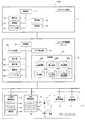
図1は、本発明の実施形態に係るリスク監視システム100の構成を示す図である。リスク監視システム100は、例えば企業で保有している金銭、設備、商品、情報等の資産を盗難等から守るために、企業で運用されている。リスク監視システム100は、クライアント端末1、リスク管理装置2、およびセキュリティデバイス3からなり、クライアント端末1とリスク管理装置2とでリスク監視装置が構成される。 FIG. 1 is a diagram showing a configuration of a
クライアント端末1は、例えばパーソナルコンピュータからなり、屋内にある管理室等に設置されている。このクライアント端末1は、リスク管理装置2と電気的に接続されている。制御部11は、CPUとメモリ等からなる。表示部12は、CRTまたはLCD等のディスプレイからなる。操作部13は、マウスとキーボードからなる。通信部14は、モデムと公知のインターフェイス回路等からなる。リードライト部15は、磁気ディスク、光ディスク、またはメモリカード等の情報記録媒体に対して情報の読み書きを行う公知のディスクドライブやカードリーダ等からなる。記憶部16は、メモリとハードディスクからなる。クライアント端末1は、本発明における出力手段の一実施形態を構成する。 The
リスク管理装置2は、サーバから構成されており、屋内にある管理室等に設置されている。このリスク管理装置2は、クライアント端末1およびセキュリティデバイス3とそれぞれ電気的に接続されている。図1では、リスク管理装置2は1台しか示されていないが、セキュリティデバイス3に含まれる各装置に対応するように複数台設けられる場合もある。制御部21、表示部22、操作部23、通信部24、リードライト部25については、上述したクライアント端末1における制御部11、表示部12、操作部13、通信部14、リードライト部15と同様である。リスク管理装置2は、本発明における第1の監視手段、第2の監視手段、算出手段、および分析手段の一実施形態を構成する。 The
記憶部26には、各種のデータベース(以下、「DB」と記す。)26a〜26fが格納されている。26aは、入退室の履歴の情報を記録した入退室履歴DB、26bは、社員等の個人情報(氏名、所属、ID等)を記録した個人情報DB、26cは、現金や設備等の資産に関する情報(資産名、保管場所、数量、価値、ID等)を記録した資産情報DB(第1のデータベース)、26dは、人や資産に付設されている無線タグから読み取った所在情報を履歴として記録したタグ履歴DB、26eは、リスクを算出するために必要なパラメータを記録したリスク算出パラメータDB(第2のデータベース)、26fは、リスクの算出結果を履歴として記録したリスク算出結果履歴DBである。なお、記憶部26には、リスクの算出および分析を行うためのプログラムや、各種の管理用プログラムが格納されているが、図1ではこれらの図示を省略してある。記憶部26は、本発明における記憶手段の一実施形態を構成する。The
27はリスク算出部であって、記憶部26から必要な情報を読み出してリスクを定量的に算出する。28はリスク分析部であって、リスク算出部27での算出結果に基づいてリスク状態を分析する。リスクの算出や分析の詳細については、後述する。
セキュリティデバイス3には、入退室管理装置4と所在管理装置5が含まれている。このほかに必要に応じて、侵入検知装置6やカメラ監視装置7などが設けられる。また、これら以外に、本人認証装置や警報・通報装置などを設けてもよい。 The
入退室管理装置4は、コントローラ41とカードリーダ42と電気錠43とを備えている。カードリーダ42は、アクセス制限を必要とする各部屋の出入口に設置され、個人が所持しているICカードに記録されているIDを読み取る装置である。電気錠43は、部屋のドアを施錠・解錠する。コントローラ41は、カードリーダ42により読み取った個人のIDと、リスク管理装置2の個人情報DB26bから取得した入退資格者のIDとを照合して、一致するか否かを判定し、該判定結果に基づいて電気錠43を制御して、ドアからの入退を許可または禁止する。入退室管理装置4での処理結果は、その都度リスク管理装置2へ送られ、入退室履歴DB26aに記録される。 The entrance /
所在管理装置5は、コントローラ51とタグリーダ52とを備えている。タグリーダ52は、人Pや資産Aに付設されている無線タグ(以下、単に「タグ」という。)Tに記録されているIDを読み取る装置である。このタグリーダ52は、建物内の部屋、フロア、通路等の随所に設けられており、タグTと無線で通信を行うことにより、当該場所に存在する人Pや資産AのIDを読み取る。また、各タグリーダ52には、場所に応じたIDが割り当てられており、タグリーダ52はタグTのIDを読み取ると、読み取ったタグIDを自身のIDとともに、その都度コントローラ51を介してリスク管理装置2へ送る。リスク管理装置2は、送られてきた情報を、タグ履歴DB26dに記録する。タグTのIDと、それを読み取ったタグリーダ52のIDとにより、人Pや資産Aの所在を管理することができる。タグを用いた資産の所在管理については、例えば、特開2005−202744号公報、特開2005−275616号公報に記載されている。 The
侵入検知装置6は、図示しないコントローラとセンサを備えており、人の侵入や侵入可能な異常状態等を検知し、検知結果をリスク管理装置2へ送信する。カメラ監視装置7は、図示しないコントローラと監視用のカメラを備えており、カメラで撮影した現場の映像をリスク管理装置2へ送信する。 The
図2は、上述したリスク監視システム100の基本的な動作を示したフローチャートである。 FIG. 2 is a flowchart showing the basic operation of the
ステップS1では、クライアント端末1において、リスクを監視する条件を設定する。例えば、監視対象とする資産や場所を特定する情報を、操作部13により入力し、この入力情報に基づいて制御部11で条件を設定する。また、監視対象を特定する情報を予め登録しておき、この登録内容に基づいて制御部11が自動的に監視条件を設定するようにしてもよい。設定された監視条件は、リスク管理装置2へ送られる。なお、リスク管理装置2で監視条件を設定することも可能である。 In step S1, the
ステップS2では、リスク管理装置2が、設定された監視条件に基づいて、セキュリティデバイス3からセキュリティ情報をリアルタイムに収集する。具体的には、入退室管理装置4のセキュリティ情報として、カードリーダ42が読み取ったID、照合結果、入退室状況、カードリーダ42や電気錠43の動作状態(正常・異常)などの情報を収集する。また、所在管理装置5のセキュリティ情報として、タグリーダ52が読み取った人Pや資産AのID、タグリーダ52のID、タグリーダ52の動作状態(正常・異常)などの情報を収集する。入退室管理装置4と所在管理装置5から収集したセキュリティ情報は、それぞれ入退室履歴DB26aとタグ履歴DB26dに格納される。 In step S2, the
ステップS3では、リスク管理装置2のリスク算出部27が、監視対象である場所(ここでは部屋とする)の脆弱性Fを算出する。ここでいう脆弱性とは、監視対象に対するアクセスの容易さを表すパラメータであって、換言すればリスクの度合いを表すパラメータでもある。脆弱性Fは0≦F≦1の値をとり、脆弱性Fが大きいほどリスクは高くなり、脆弱性Fが小さいほどリスクは低くなる。この脆弱性は、静的側面と動的側面の両方から算出される。静的脆弱性は、建物における出入口などのアクセス拠点ごとに設定された固有の定数や、セキュリティデバイス3の各装置ごとに設定された固有の定数に基づいて算出され、動的脆弱性は、静的脆弱性に、セキュリティデバイス3からリアルタイムに収集したセキュリティ情報を加味して算出される。脆弱性の算出方法の詳細については、後述する。 In step S3, the
ステップS4では、リスク算出部27が、リスク算出パラメータDB26eから、犯罪発生確率Nを取得する。犯罪発生確率とは、犯罪の発生頻度を表すパラメータであって、過去の犯罪データに基づき、対象地周辺の街の特性等により決定される定数である。 In step S4, the
ステップS5では、リスク算出部27が、資産情報DB26cから、各部屋における資産価値Aを取得する。この資産価値Aは、その部屋に保管されている金銭、設備、商品、情報などの各種資産を300万円、1000万円などの金額で表した情報である。 In step S5, the
ステップS6では、リスク算出部27が、ステップS3〜S5で得られた脆弱性F、犯罪発生確率N、資産価値Aに基づいて、リスク値PML(Probable Maximum Loss;予想最大損失率)を以下の式により算出する。
PML=犯罪発生確率(N)×脆弱性(F)×資産価値(A) …(1)
このPMLが、その部屋の最終的なリスクの度合いを表すリスク値となる。上式からわかるように、リスク値PMLは金額を以って表される。算出されたリスク値PMLは、リスク算出結果履歴DB26fに格納される。In step S6, the
PML = Crime occurrence probability (N) x Vulnerability (F) x Asset value (A) (1)
This PML is a risk value representing the final risk level of the room. As can be seen from the above equation, the risk value PML is represented by a monetary amount. The calculated risk value PML is stored in the risk calculation
ステップS7では、リスク分析部28が、ステップS6で得られたリスク値PMLに基づいて、リスク状態を分析する。具体的には、リスクを5段階のレベルに分類したり、リスクの上昇した原因を解析したり、予想侵入ルートを判別したりする処理を行う。これらの詳細については後述する。リスク分析部28での分析結果は、リスク算出結果履歴DB26fに格納されるとともに、通信部24を介して、クライアント端末1へ送信される。 In step S7, the
ステップS8では、クライアント端末1が、リスク管理装置2から送られてきた分析結果に基づいて、リスク状態を表示部12に表示する。この表示の詳細については後述する。 In step S <b> 8, the
ステップS9では、リスク管理装置2が、監視を終了するか否かを判定する。監視の終了は、操作部13(または操作部23)で所定の操作を行うことにより行われる。監視終了の操作が行なわれると(ステップS9:YES)、処理を終了し、監視終了の操作が行なわれなければ(ステップS9:NO)、ステップS10へ移行して、所定時間tが経過したか否かを判定する。この所定時間tは、ステップS2でセキュリティデバイス3から定期的にデータを収集する場合の時間間隔であって、例えば30秒や1分などの値に設定される。したがって、本発明でいうリアルタイムとは、この所定時間tを考慮に入れた場合のリアルタイムをいう。所定時間tが経過してなければ(ステップS10:NO)、ステップS9へ戻り、所定時間tが経過すると(ステップS10:YES)、ステップS2へ移行して再びセキュリティデバイス3からセキュリティ情報を収集し、ステップS3以降の処理を実行する。 In step S9, the
次に、図2のステップS3における脆弱性の算出方法を、図3〜図6を参照しながら、具体例に即して説明する。最初に、静的脆弱性の算出方法について述べる。 Next, the vulnerability calculation method in step S3 of FIG. 2 will be described according to a specific example with reference to FIGS. First, we will describe how to calculate static vulnerabilities.
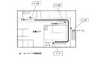
図3は、企業、官庁、学校、病院等の敷地内における建物配置の一例を示した図、図4は、建物のうち本館1階のフロア配置を示した図、図5は、本館2階のフロア配置を示した図である。図5のように、本館2階にはサーバルームがあり、このサーバルームへのアクセスに対する静的脆弱性について考える。サーバルームへ侵入するには、図3のように、まず正門か裏門のいずれかを通らなければならない。正門と裏門には警備員がいるが、所定の受付を済ませれば、基本的には誰でも入門できるので、正門と裏門におけるアクセス制限はないと考えてよい。そこで、正門と裏門における脆弱性の値はいずれも「1.0」とする。また、正門や裏門を通らずに、図4に示すフェンスを乗り越えて敷地内に侵入するケースもありうる。この場合、フェンスは誰でも常に乗り越えられるとは限らないので、フェンスにおける脆弱性の値は、正門と裏門における脆弱性より小さい「0.75」とする。これらの脆弱性の数値は、リスク管理装置2のリスク算出パラメータDB26eにあらかじめ記憶されている。 3 is a diagram showing an example of a building layout in a company, government office, school, hospital, etc. FIG. 4 is a diagram showing the floor layout of the first floor of the main building, and FIG. 5 is the second floor of the main building. It is the figure which showed the floor arrangement | positioning. As shown in FIG. 5, there is a server room on the 2nd floor of the main building, and a static vulnerability to access to this server room is considered. In order to enter the server room, it is necessary to first pass through either the main gate or the back gate as shown in FIG. There are security guards at the main gate and the back gate, but if you complete the prescribed reception, basically anyone can enter, so you can think that there are no access restrictions at the main gate and the back gate. Therefore, the vulnerability value at the main gate and the back gate is both set to “1.0”. In addition, there may be a case where the user enters the site by going over the fence shown in FIG. 4 without passing through the main gate and the back gate. In this case, since everyone cannot always get over the fence, the vulnerability value in the fence is set to “0.75”, which is smaller than the vulnerability in the main gate and the back gate. The numerical values of these vulnerabilities are stored in advance in the risk
敷地内に入った後、サーバルームへ侵入するには、次に本館内に入らなければならない。図4のように、本館1階への侵入経路としては、外来者入口、社員通用口1、社員通用口2、および非常口の4つがある。ここで、外来者入口と、社員通用口1と、社員通用口2とは、常時扉が開いているので、誰でも侵入することができる。したがって、これらの場所における脆弱性の値はいずれも「1.0」とする。これに対して、非常口は常時扉が閉まっているので、他の入口よりは侵入の可能性が幾分低くなる。そこで、非常口における脆弱性の値は、外来者入口などにおける脆弱性より小さい「0.75」とする。これらの脆弱性の数値も、リスク管理装置2のリスク算出パラメータDB26eにあらかじめ記憶されている。 After entering the premises, you must enter the main hall to enter the server room. As shown in FIG. 4, there are four intrusion routes to the first floor of the main building, namely, an outsider entrance, an
本館内に入った後、サーバルームへ侵入するには、図5のように、本館2階のカードゲートを通過しなければならない。カードゲートは、図1の入退室管理装置4とドア(扉)とから構成され、カードリーダ42がICカードから読み取ったIDの照合結果が正常であれば、電気錠43が解錠されてドアから入場することが許可され、IDの照合結果が正常でなければ、電気錠43が施錠されてドアからの入場が禁止される。このため、ICカードを所持しない者や、正常でないカードを所持している者は、カードゲートから内部への侵入ができなくなる。したがって、各カードゲートにおける脆弱性はかなり低くなるが、カードリーダ42が誤動作したり、電気錠43を破壊して強制的に侵入するケースもないとはいえないので、ここでは各カードゲートにおける脆弱性を「0.25」とする。この脆弱性の数値も、リスク管理装置2のリスク算出パラメータDB26eにあらかじめ記憶されている。 To enter the server room after entering the main building, you must pass through the card gate on the 2nd floor of the main building as shown in FIG. The card gate is composed of the entrance /
カードゲートを通過した後、サーバルームへ侵入するには、最終的に、サーバルームの入口に設けられている入退室管理装置4のカードリーダ42にICカードを読み取らせてID照合を行い、電気錠43を解錠しなければならない。このサーバルーム入口の入退室管理装置4は、上述したカードゲートの入退室管理装置4と同じものであるが、例えば、設置時期が古いために誤動作の回数が増えているという事情があると仮定して、サーバルームの入口における脆弱性は「0.5」とする。この脆弱性の数値も、リスク管理装置2のリスク算出パラメータDB26eにあらかじめ記憶されている。 In order to enter the server room after passing through the card gate, the
リスク管理装置2のリスク算出部27は、上述した各拠点における脆弱性の値を用いて、サーバルームの最終的な脆弱性の値を算出する。この場合の算出アルゴリズムの例を図6に示す。図6において、正門、裏門、フェンスの脆弱性はそれぞれ「1.0」「1.0」「0.75」であり、これらのうちの最大値f1=1.0が採用される。これは、正門と裏門とフェンスとは、侵入経路の点で直列的な関係になく、並列的な関係にあるので、最も大きい脆弱性を採用するのが、リスクを評価するうえで合理的だからである。以下で脆弱性の最大値を採用する理由も同様である。 The
次に、本館1階の社員通用口1、社員通用口2、外来者入口、非常口の脆弱性はそれぞれ「1.0」「1.0」「1.0」「0.75」であり、これらのうちの最大値f2=1.0が採用される。そして、f1とf2の積(AND)をとってf3=1.0が算出される。この場合は、正門、裏門またはフェンス経由で敷地内に入ってないと、本館1階に侵入するのは物理的に不可能なことから、正門や裏門等と、本館1階の社員通用口や外来者入口等とは、侵入経路の点で直列的な関係にあるので、両者の脆弱性の積を演算することになる。以下で積の演算を行う理由も同様である。 Next, the vulnerabilities of
また、本館2階の社員カードゲート1、社員カードゲート2、外来者カードゲートの脆弱性はいずれも「0.25」であるから、最大値としてf4=0.25が採用される。そして、f3とf4の積(AND)をとってf5=0.25が算出される。さらに、サーバルーム入口における脆弱性はf6=0.5であり、f5とf6との積(AND)であるF=0.125が、最終的なサーバルームの静的脆弱性となる。 Further, since the vulnerability of the
セキュリティデバイス3が監視対象の異常を検出していない場合は、上記のアルゴリズムにより算出した静的脆弱性Fが、そのままサーバルームの脆弱性となり、これに、前記(1)式の犯罪発生確率Nと資産価値Aとを乗じた結果が、サーバルームのリスク値PMLとなる。しかしながら、これだけでは、監視対象に異常が発生した場合に、それをリスク値PMLに反映させることができず、リスクの増大に対応することができない。そこで、本発明では、静的脆弱性に、セキュリティデバイス3からリアルタイムに収集したセキュリティ情報を反映させることによって、動的脆弱性を算出する。 When the
例えば、入退室管理装置4から取得した情報に、施錠エラーの発生したことが含まれている場合、その入退室管理装置4が設置されている出入口の脆弱性は増加する。いま、図5における社員カードゲート1で施錠エラーが発生したと仮定すると、リスク管理装置2の制御部21は、リスク算出パラメータDB26eに記録されている社員カードゲート1の脆弱性を0.25から0.5に変更する。この結果、図7に示すように、f4=0.5、f5=0.5となり、最終的なサーバルームの脆弱性はF=0.25に上昇する。 For example, if the information acquired from the entrance /
また、例えば、入退室管理装置4から取得した情報に、ドア(扉)が開きっぱなしになっていることが含まれている場合も、その入退室管理装置4が設置されている出入口の脆弱性は増加する。いま、図5におけるサーバルームの入口のドアが開放されているものと仮定すると、リスク管理装置2の制御部21は、リスク算出パラメータDB26eに記録されているサーバルーム入口の脆弱性を0.5から1.0に変更する。この結果、図8に示すように、f6=1.0となり、最終的なサーバルームの脆弱性はF=0.5に上昇する。 Further, for example, when the information acquired from the entrance /
このようにして、セキュリティデバイス3から収集したセキュリティ情報に基づいて、リスク算出パラメータDB26eに記録されている静的脆弱性のパラメータの値を変更することによって、セキュリティ状態に応じた動的脆弱性をリアルタイムに算出することができる。このため、監視対象に異常が発生した場合には、これが最終的なリスク値PMLに反映されるので、リスクの増大に速やかに対応することができる。 In this way, by changing the value of the static vulnerability parameter recorded in the risk
次に、図2のステップS8での表示の具体例につき、図9〜図15を参照しながら説明する。 Next, a specific example of the display in step S8 in FIG. 2 will be described with reference to FIGS.
図9は、クライアント端末1の表示部12に表示される監視画面12aの一例を示している。この監視画面12aには、リスク管理装置2が監視する建物のリスク状態が表示される。すなわち、リスク情報表示部30には、建物の各フロアごとのリスク情報がリアルタイムに表示され、リスクレベル表示部36には、5段階のリスクレベル(レベル1〜レベル5)の中から、現在のリスクレベルが表示される。レベル1は最もリスクが低く、レベル5は最もリスクが高い状態である。37は、後述の履歴表示画面12b(図11)へ遷移するための履歴参照ボタンである。なお、これらの情報を表示するための表示プログラムは、記憶部16に格納されている。 FIG. 9 shows an example of the
リスク情報表示部30において、31はフロアレイアウト図であって、資産のある部屋には、資産33を表すマークA1〜A5,B1〜B4が表示されている。A1〜A5は現金の資産を表しており、B1〜B4は現金以外の設備、商品等の資産を表している。資産が他の場所へ移された場合は、符号34で示すような移動軌跡が表示される。前述のように、各資産33にはタグTが付設されており、所在管理装置5により資産33の所在が検出されるので、資産33に移動があった場合は、リスク管理装置2でこれを把握することができる。なお、この移動軌跡34は、資産33がその場所で継続して検出されている時間が一定時間未満の場合に、直前に検出した場所からの移動経路として表示される。資産33がその場所で一定時間以上継続して検出されている場合は、移動軌跡34は表示されない。 In the risk
また、リスク情報表示部30において、32は各部屋や各扉のリスクレベルを表示する個別リスク表示部であって、2時間前から現在までの各場所のリスクレベルの推移がバーグラフ35で表示されている。バーグラフ35は、リスクのレベルに応じて色分け表示され、色の濃いバーほど高いリスクレベルを表している。上述したリスクレベル表示部36には、現在時点での各場所のリスクレベルのうちで最も高いリスクレベルの値が表示される。図9は、異常が発生していない正常状態の例なので、現在時点での各場所のリスクレベルは全て「レベル1」であり、リスクレベル表示部36には「レベル1」が表示されている。 In the risk
上述したリスクレベルは、図2のステップS7の処理において決定される。すなわち、リスク管理装置2のリスク分析部28は、前記(1)式により算出された各場所のリスク値PMLをリスク算出部27から受け取ると、当該リスク値PMLを閾値と比較して、リスク値をレベル1〜レベル5のいずれかに分類する。前述のように、リスク値PMLは金額で表されるため、閾値として4つの金額α,β,γ,δ(α<β<γ<δ)があらかじめ設定されている。そして、リスク分析部28は、PMLの金額に応じて、レベルを次のように決定する。
0≦PML<αの場合 → 「レベル1」
α≦PML<βの場合 → 「レベル2」
β≦PML<γの場合 → 「レベル3」
γ≦PML<δの場合 → 「レベル4」
δ≦PMLの場合 → 「レベル5」
これらのレベル値は、リスク算出結果履歴DB26fに順次蓄積される。クライアント端末1は、リスク算出結果履歴DB26fに蓄積されたレベル値に基づいて、図9におけるリスクレベル表示部36に、現在のリスクレベル(最高値)を表示するとともに、個別リスク表示部32に、2時間前から現在までの各場所のリスクレベルをバーグラフ35で表示する。The risk level described above is determined in the process of step S7 in FIG. That is, when the
If 0 ≦ PML <α → “
If α ≦ PML <β → “
If β ≦ PML <γ → “
If γ ≦ PML <δ → “
If δ ≦ PML → “
These level values are sequentially accumulated in the risk calculation
図10は、異常が発生した場合の監視画面12aの例を示している。ここでの異常は、3号館1階において、入退室管理装置4(図1)が設けられている扉Bが、何らかの原因により開放されたままになっていて、扉Bからフロア内に外部の者が侵入可能となっている状態を指す。扉Bが開放状態になっていることは、入退室管理装置4から送られてくるセキュリティ情報に基づいて、リスク管理装置2で判別することができる。リスク管理装置2では、扉Bの開放状態が判別されると、扉Bの脆弱性の値を「1.0」に変更する。そして、リスク算出部27は、変更後の脆弱性の値を用いて、3号館1階における各部屋のリスク値PMLを算出する。また、リスク分析部28は、算出されたリスク値PMLに基づき、上述した基準に従って、各部屋のリスクレベルを決定する。 FIG. 10 shows an example of the
一例として、資産A5のある部屋のリスクレベルが「レベル5」、資産B1および資産B4のある部屋のリスクレベルが「レベル3」、その他の部屋のリスクレベルが「レベル1」に決定されたものとする。これらの結果は、クライアント端末1に送られる。これにより、監視画面12aの3号館1階の個別リスク表示部32には、資産A5のある部屋(セキュリティルーム)の現在のリスクレベルとして、符号Mで示すようなレベル5に相当する色のバーが表示される。また、資産B1のある部屋(機材ルーム)および資産B4のある部屋(商談ルーム)の現在のリスクレベルとして、レベル3に相当する色のバーが表示される。なお、個別リスク表示部32に表示される部屋や扉は、リスクレベルの高い順に自動的に並べ替えられる。資産A5のある部屋のリスクレベルが「レベル5」となる結果、リスクレベル表示部36には「レベル5」が表示される。さらに、フロアレイアウト図31において、資産A5,B1,B4のある部屋は、それぞれのリスクレベルに対応した色で表示される。これによって、各部屋のリスクレベルを一目瞭然に把握することができる。 As an example, the risk level of the room with the asset A5 is determined as “
また、リスク分析部28は、リスクレベルが「レベル5」に上昇した原因と対処方法とを調べるとともに、扉Bが開放されている場合の想定される侵入ルートを予測し、これらの結果をクライアント端末1へ送る。これにより、監視画面12aのフロアレイアウト図31に、破線で示すような予測侵入ルート38が表示される。また、監視画面12aの下部には、メッセージ欄45が表示され、ここにリスク発生場所、リスク発生原因、対処方法が表示される。したがって、この表示を見ることにより、リスクへの対応を迅速かつ正確に行うことができる。なお、メッセージ欄45は、リスクが所定レベル以上(例えばレベル4以上)の場合に表示されるが、所定レベル未満の場合にも何らかのメッセージを表示するようにしてもよい。 Further, the
図11は、クライアント端末1の表示部12に表示される履歴表示画面12bの一例を示している。この履歴表示画面12bは、図9および図10で示した履歴参照ボタン37をクリックすることにより表示される。履歴表示画面12bには、リスク算出結果履歴DB26fに記録されている履歴に基づいて、所定期間におけるリスクの履歴が表示される。56は履歴の検索期間を入力するための検索期間入力欄、57は検索を実行するための検索ボタンである。58は履歴表示部であって、ここには、検索期間入力欄56で指定された期間における各場所のリスクレベルの推移が、バーグラフで表示される。このバーグラフは、図9等のバーグラフ35と同様に、リスクレベルに応じて色分けされて表示される。図11の例では、検索期間が特定の1日なので、当該日の24時間にわたる各場所のリスクレベルの変化がバーグラフで表示されている。59は履歴検索の結果をリスト形式で表示する検索結果表示部である。リスクレベル表示部36は、図9および図10に示したものと同じであり、ここには前述のように現在のリスクレベルが表示される(因みに、このレベルは履歴表示部58の表示とは直接関係がない)。55は監視ボタンであり、このボタンをクリックすると、図9等の監視画面12aへ戻る。 FIG. 11 shows an example of a
図12は、何日かにわたる検索期間を指定した場合の履歴表示画面12bの表示例を示している。図12では、図11と同一部分には同一符号を付してある。図12の例では、検索期間が6日間であり、当該期間にわたる各場所のリスクレベルの推移がバーグラフで表示されている。ここでは、1日を適当な時間帯に分け、各時間帯のバーグラフは、当該時間帯における最大のリスクレベルに対応した色で表示されるようになっている。 FIG. 12 shows a display example of the
なお、他の実施形態として、図11の履歴表示画面12bにおいて、履歴表示部58の時刻欄をクリックすることで、期間のスケールが変化するようにしてもよい。例えば、クリックのたびに、1時間、1日間、1週間、1か月間、3か月間というようにスケールがサイクリックに切り替わり、それぞれの期間に応じた履歴が表示されるようにしてもよい。 As another embodiment, the scale of the period may be changed by clicking the time column of the
図13は、過去のある時点における詳細なリスク状態を表示する詳細履歴表示画面12cの一例を示している。この詳細履歴表示画面12cは、例えば、図11の履歴表示画面12bの履歴表示部58において、バーグラフ表示領域における表示したい時点に相当する場所をクリックすることで表示される。クリックする場所に応じて、例えば10分単位で時点を指定することができる。詳細履歴表示画面12cの表示内容は、図9や図10の監視画面12aの表示内容と基本的に同じであり、個別リスク表示部32に、指定された時点(前後を含む)におけるリスクレベルがバーグラフ35で表示される。46は、クリックにより指定された時点を表す時点表示部である。このような詳細履歴表示画面12cを表示することで、過去の任意の時点における詳細なリスク状態を把握することができる。 FIG. 13 shows an example of a detailed
ここでは、履歴表示画面12bにおいてバーグラフ表示領域をクリックすることで、詳細履歴表示画面12cに切り替わるとともに時点が指定されるようにしたが、これに代えて、履歴表示画面12bに詳細履歴表示用のボタンを設け、このボタンが操作されたときに詳細履歴表示画面12cを表示し、詳細履歴表示画面12cの時点入力欄に時点を入力することによって、時点を指定するようにしてもよい。 Here, by clicking the bar graph display area on the
以上述べたように、上述した実施形態によれば、リスク管理装置2において、資産の監視結果と、セキュリティ状態の監視結果とに基づいて、建物の所定場所におけるリスクが定量的に算出・分析され、その結果がクライアント端末1の表示部12に表示されるので、守るべき資産に対するリスクの状況をリアルタイムに把握することができ、状況に応じて適切な対策を講じることが可能となる。また、リスクが金額として算出されるので、資産の価値に応じたリスクを的確に把握することができる。 As described above, according to the above-described embodiment, the
また、資産の所在をリアルタイムに監視し、資産の移動があった場合に、当該資産の移動軌跡34(図9等)を表示するので、資産が移動しても、移動軌跡34の表示により資産のある場所を正確に把握することができる。また、履歴表示画面12bや詳細履歴表示画面12cを表示するようにしたので、現在のリスク状態だけでなく、過去のリスク状態も容易に知ることができるとともに、必要に応じて、指定した所定時点での詳細な情報を把握することができる。 In addition, the location of the asset is monitored in real time, and when the asset is moved, the movement trajectory 34 (FIG. 9 and the like) of the asset is displayed. It is possible to accurately grasp the location of the. Further, since the
さらに、監視画面12aのメッセージ欄45(図10)において、リスクが上昇した原因や対処方法が表示されるので、リスクを下げるための適切な措置を速やかにとることができるとともに、監視画面12aのフロアレイアウト図31に予測侵入ルート38が表示されるので、侵入を阻止するための適切な措置を速やかにとることができる。 Furthermore, since the cause of the risk and the coping method are displayed in the message field 45 (FIG. 10) of the
本発明では、以上述べた以外にも種々の実施形態を採用することができる。例えば、図14に示すように、監視画面12aにおいて、資産33のマークにマウスポインタ48を当てた際に、当該資産33の資産価値(金額)49が表示されるようにしてもよい。あるいは、マウスポインタ48を操作しなくても、最初から全ての資産33につき、資産価値49が表示されるようにしてもよい。また、同じ場所に現金と現金以外の資産とが並存する場合は、それらの個々の資産価値と、合計の資産価値とを表示するようにしてもよい。 In the present invention, various embodiments other than those described above can be adopted. For example, as shown in FIG. 14, when the
図9〜図14においては、リスクレベル表示部36に、全フロアのリスクレベルの中から最高レベルの値だけを表示するようにしたが、図15に示すように、リスクレベル表示部36において、各フロアごとに、当該フロアのリスクレベルの最高値を表示するようにしてもよい。また、図示は省略するが、他の実施形態として、リスクレベル表示部36にレベル1〜レベル5を常時表示し、該当するレベルだけを高輝度表示、拡大表示または点滅表示するようにしてもよい。 9 to 14, the risk
さらに、図1においては、クライアント端末1とリスク管理装置2とを分離した構成としたが、クライアント端末1をリスク管理装置2に統合し、リスク管理装置2の表示部22に、図9〜図15で示したような画面を表示するようにしてもよい。 Further, in FIG. 1, the
1 クライアント端末
2 リスク管理装置
3 セキュリティデバイス
4 入退室管理装置
5 所在管理装置
12 表示部
12a 監視画面
12b 履歴表示画面
12c 詳細履歴表示画面
26 記憶部
27 リスク算出部
28 リスク分析部
30 リスク情報表示部
32 個別リスク表示部
33 資産
34 移動軌跡
36 リスクレベル表示部
38 予測侵入ルート
100 リスク監視システム
A 資産
T 無線タグDESCRIPTION OF
Claims (8)
Translated fromJapanese建物の内部にある資産に関する情報を記憶した第1のデータベースと、
建物の所定場所へ至る経路の各拠点におけるアクセスの容易さを表す静的脆弱性の値を記憶した第2のデータベースと、
前記第1のデータベースの情報に基づいて、前記建物の内部にある資産を監視する第1の監視手段と、
前記セキュリティデバイスからの情報を取得して、建物の所定場所におけるセキュリティ状態を監視する第2の監視手段と、
前記第1および第2の監視手段の監視結果に基づいて、前記所定場所におけるリスクを定量的に算出する算出手段と、
前記算出手段の算出結果に基づいてリスク状態を分析する分析手段と、
前記分析手段による分析結果を出力する出力手段と、
を備え、
前記算出手段は、
前記セキュリティデバイスが異常を検出した場合に、前記第2の監視手段が取得したセキュリティデバイスからの情報に基づいて、前記第2のデータベースにおける異常が検出された拠点の静的脆弱性の値を変更することにより、各拠点のセキュリティ状態に応じた動的脆弱性をリアルタイムに算出し、当該動的脆弱性の値を用いて前記所定場所における最終的な脆弱性の値を算出し、
前記第1の監視手段の監視結果から得られる前記所定場所にある資産の価値と、前記所定場所における最終的な脆弱性の値とを用いて、当該所定場所におけるリスクを算出する
ことを特徴とするリスク監視装置。A risk monitoring device connected to a security device and monitoring a risk in a building,
A first database storing information about assets inside the building;
A second database storing static vulnerability values representing the ease of access at each site on the route to a predetermined location of the building;
First monitoring means for monitoring assets in the buildingbased on the information in the first database ;
Second monitoring means for acquiring information from the security device and monitoring a security state at a predetermined location of the building;
Calculation means for quantitatively calculating the risk at the predetermined location based on the monitoring results of the first and second monitoring means;
Analyzing means for analyzing a risk state based on a calculation result of the calculating means;
Output means for outputting an analysis result by the analysis means;
Equipped witha,
The calculating means includes
When the security device detects an abnormality, the static vulnerability value of the base where the abnormality is detected in the second database is changed based on the information from the security device acquired by the second monitoring unit. By calculating the dynamic vulnerability according to the security status of each site in real time, using the dynamic vulnerability value, calculate the final vulnerability value at the predetermined location,
The risk at the predetermined location is calculated using the value of the asset at the predetermined location obtained from the monitoring result of the first monitoring means and the final vulnerability value at the predetermined location. A risk monitoring device characterized by that.
前記第1の監視手段は、前記資産の所在と金額とを監視し、
前記算出手段は、前記所定場所におけるリスクを金額として算出することを特徴とするリスク監視装置。In the risk monitoring device according to claim 1,
The first monitoring means monitors the location and amount of the asset;
The risk monitoring apparatus, wherein the calculating means calculates a risk at the predetermined place as a monetary amount.
前記資産には、所在管理のための無線タグが付設されており、
前記第1の監視手段は、前記無線タグの情報に基づいて資産の所在をリアルタイムに監視し、
前記出力手段は、前記資産の移動があった場合に、当該資産の移動軌跡を表示することを特徴とするリスク監視装置。In the risk monitoring device according to claim 1,
The asset is provided with a wireless tag for location management,
The first monitoring means monitors the location of the asset in real time based on the information of the wireless tag,
The risk monitoring apparatus, wherein the output means displays a movement trajectory of the asset when the asset has moved.
前記分析手段による分析結果を蓄積して記憶する記憶手段を備え、
前記出力手段は、前記記憶手段に記憶されている情報に基づいて、前記リスク状態の履歴を表示し、前記履歴における所定時点が指定された場合に、当該時点での詳細なリスク状態を表示することを特徴とするリスク監視装置。In the risk monitoring device according to claim 1,
Storage means for accumulating and storing analysis results by the analysis means;
The output means displays a history of the risk state based on information stored in the storage means, and when a predetermined time point in the history is designated, displays a detailed risk state at the time point A risk monitoring device characterized by that.
前記分析手段は、前記算出手段で算出されたリスクをその値に応じて複数のレベルに分類し、リスクのレベルが所定レベル以上の場合に、前記セキュリティデバイスからの情報に基づいて、リスクが高くなった原因を判別し、
前記出力手段は、前記分析手段が判別した原因を表示することを特徴とするリスク監視装置。In the risk monitoring device according to claim 1,
The analysis unit classifies the risk calculated by the calculation unit into a plurality of levels according to the value, and when therisk level is equal to or higher than a predetermined level, the risk is high based on information from the security device. Determine the cause,
The risk monitoring apparatus, wherein the output means displaysa causedetermined by the analyzing means .
前記分析手段は、前記第2の監視手段が扉のセキュリティ状態の変化を検出したことに基づいて、想定される侵入ルートを予測し、
前記出力手段は、前記分析手段が予測した侵入ルートを表示することを特徴とするリスク監視装置。In the risk monitoring device according to claim 1,
The analysis means predicts an assumed intrusion route based on the second monitoring means detecting a change in the security state of the door,
The risk monitoring apparatus, wherein the output means displays an intrusion route predicted by the analysis means.
前記リスク監視装置に接続されたセキュリティデバイスと、
を備えたことを特徴とするリスク監視システム。The risk monitoring device according to any one of claims 1 to 6,
A security device connected to the risk monitoring device;
A risk monitoring system characterized by comprising:
第1の監視手段が、前記第1のデータベースの情報に基づいて、前記建物の内部にある資産を監視するステップと、
第2の監視手段が、前記セキュリティデバイスからの情報を取得して、建物の所定場所におけるセキュリティ状態を監視するステップと、
前記セキュリティデバイスが異常を検出した場合に、算出手段が、前記第2の監視手段が取得したセキュリティデバイスからの情報に基づいて、前記第2のデータベースにおける異常が検出された拠点の静的脆弱性の値を変更することにより、各拠点のセキュリティ状態に応じた動的脆弱性をリアルタイムに算出し、当該動的脆弱性の値を用いて前記所定場所における最終的な脆弱性の値を算出するステップと、
前記算出手段が、前記第1の監視手段の監視結果から得られる前記所定場所にある資産の価値と、前記所定場所における最終的な脆弱性の値とを用いて、当該所定場所におけるリスクを定量的に算出するステップと、
分析手段が、前記算出手段の算出結果に基づいてリスク状態を分析するステップと、
出力手段が、前記分析手段による分析結果を出力するステップと、
を備えたことを特徴とするリスク監視方法。Afirst database connected to the security deviceand storing information on assets inside the building, and a static vulnerability value indicating the ease of access at each site on the route to the predetermined location of the building A risk monitoring method using a risk monitoring device for monitoring risks ina building.
First monitoring means for monitoring an asset in the buildingbased on information in the first database ;
Second monitoring means for acquiring information from the security device and monitoring a security state at a predetermined location of the building;
When the security device detects an abnormality, the calculation means uses the information from the security device acquired by the second monitoring means, and the static vulnerability of the base where the abnormality is detected in the second database By changing the value, the dynamic vulnerability corresponding to the security status of each site is calculated in real time, and the final vulnerability value at the predetermined location is calculated using the dynamic vulnerability value Steps,
The calculation means quantifies the risk at the predetermined locationusing the value of the asset at the predetermined location obtained from the monitoring result of the first monitoring means and the final vulnerability value at the predetermined location. Calculating automatically,
An analyzing unit analyzing a risk state based on a calculation result of the calculating unit;
An output means for outputting an analysis result by the analysis means;
A risk monitoring method characterized by comprising:
Priority Applications (1)
| Application Number | Priority Date | Filing Date | Title |
|---|---|---|---|
| JP2006288142AJP4895110B2 (en) | 2006-10-23 | 2006-10-23 | Risk monitoring device, risk monitoring system, and risk monitoring method |
Applications Claiming Priority (1)
| Application Number | Priority Date | Filing Date | Title |
|---|---|---|---|
| JP2006288142AJP4895110B2 (en) | 2006-10-23 | 2006-10-23 | Risk monitoring device, risk monitoring system, and risk monitoring method |
Publications (2)
| Publication Number | Publication Date |
|---|---|
| JP2008107930A JP2008107930A (en) | 2008-05-08 |
| JP4895110B2true JP4895110B2 (en) | 2012-03-14 |
Family
ID=39441255
Family Applications (1)
| Application Number | Title | Priority Date | Filing Date |
|---|---|---|---|
| JP2006288142AExpired - Fee RelatedJP4895110B2 (en) | 2006-10-23 | 2006-10-23 | Risk monitoring device, risk monitoring system, and risk monitoring method |
Country Status (1)
| Country | Link |
|---|---|
| JP (1) | JP4895110B2 (en) |
Families Citing this family (81)
| Publication number | Priority date | Publication date | Assignee | Title |
|---|---|---|---|---|
| JP5081035B2 (en)* | 2008-03-28 | 2012-11-21 | 株式会社竹中工務店 | Crime risk assessment apparatus and crime risk assessment program |
| US9411327B2 (en) | 2012-08-27 | 2016-08-09 | Johnson Controls Technology Company | Systems and methods for classifying data in building automation systems |
| MA40078A (en)* | 2014-06-03 | 2015-12-10 | The Security Oracle Inc | Defense and denial method |
| US10534326B2 (en) | 2015-10-21 | 2020-01-14 | Johnson Controls Technology Company | Building automation system with integrated building information model |
| US12196437B2 (en) | 2016-01-22 | 2025-01-14 | Tyco Fire & Security Gmbh | Systems and methods for monitoring and controlling an energy plant |
| US11947785B2 (en) | 2016-01-22 | 2024-04-02 | Johnson Controls Technology Company | Building system with a building graph |
| US11268732B2 (en) | 2016-01-22 | 2022-03-08 | Johnson Controls Technology Company | Building energy management system with energy analytics |
| US11768004B2 (en) | 2016-03-31 | 2023-09-26 | Johnson Controls Tyco IP Holdings LLP | HVAC device registration in a distributed building management system |
| US10505756B2 (en) | 2017-02-10 | 2019-12-10 | Johnson Controls Technology Company | Building management system with space graphs |
| US11774920B2 (en) | 2016-05-04 | 2023-10-03 | Johnson Controls Technology Company | Building system with user presentation composition based on building context |
| US10417451B2 (en) | 2017-09-27 | 2019-09-17 | Johnson Controls Technology Company | Building system with smart entity personal identifying information (PII) masking |
| JP6712921B2 (en)* | 2016-07-21 | 2020-06-24 | 株式会社竹中工務店 | Crime damage amount estimation device and program |
| KR101921911B1 (en)* | 2016-12-23 | 2018-11-28 | 주식회사 심플비트 | Physical Security Information System and Method thereof |
| US10684033B2 (en) | 2017-01-06 | 2020-06-16 | Johnson Controls Technology Company | HVAC system with automated device pairing |
| US11900287B2 (en) | 2017-05-25 | 2024-02-13 | Johnson Controls Tyco IP Holdings LLP | Model predictive maintenance system with budgetary constraints |
| US10515098B2 (en) | 2017-02-10 | 2019-12-24 | Johnson Controls Technology Company | Building management smart entity creation and maintenance using time series data |
| US11764991B2 (en) | 2017-02-10 | 2023-09-19 | Johnson Controls Technology Company | Building management system with identity management |
| US11307538B2 (en) | 2017-02-10 | 2022-04-19 | Johnson Controls Technology Company | Web services platform with cloud-eased feedback control |
| US11360447B2 (en) | 2017-02-10 | 2022-06-14 | Johnson Controls Technology Company | Building smart entity system with agent based communication and control |
| US10417245B2 (en) | 2017-02-10 | 2019-09-17 | Johnson Controls Technology Company | Building management system with eventseries processing |
| US10452043B2 (en) | 2017-02-10 | 2019-10-22 | Johnson Controls Technology Company | Building management system with nested stream generation |
| US11994833B2 (en) | 2017-02-10 | 2024-05-28 | Johnson Controls Technology Company | Building smart entity system with agent based data ingestion and entity creation using time series data |
| US10854194B2 (en) | 2017-02-10 | 2020-12-01 | Johnson Controls Technology Company | Building system with digital twin based data ingestion and processing |
| US12184444B2 (en) | 2017-02-10 | 2024-12-31 | Johnson Controls Technology Company | Space graph based dynamic control for buildings |
| US11280509B2 (en) | 2017-07-17 | 2022-03-22 | Johnson Controls Technology Company | Systems and methods for agent based building simulation for optimal control |
| US11042144B2 (en) | 2017-03-24 | 2021-06-22 | Johnson Controls Technology Company | Building management system with dynamic channel communication |
| US11327737B2 (en) | 2017-04-21 | 2022-05-10 | Johnson Controls Tyco IP Holdings LLP | Building management system with cloud management of gateway configurations |
| US10788229B2 (en) | 2017-05-10 | 2020-09-29 | Johnson Controls Technology Company | Building management system with a distributed blockchain database |
| JP7184797B2 (en) | 2017-05-25 | 2022-12-06 | ジョンソン コントロールズ テクノロジー カンパニー | Model predictive maintenance system for building equipment |
| US11022947B2 (en) | 2017-06-07 | 2021-06-01 | Johnson Controls Technology Company | Building energy optimization system with economic load demand response (ELDR) optimization and ELDR user interfaces |
| WO2018232147A1 (en) | 2017-06-15 | 2018-12-20 | Johnson Controls Technology Company | Building management system with artificial intelligence for unified agent based control of building subsystems |
| US11422516B2 (en) | 2017-07-21 | 2022-08-23 | Johnson Controls Tyco IP Holdings LLP | Building management system with dynamic rules with sub-rule reuse and equation driven smart diagnostics |
| US10648692B2 (en) | 2017-07-27 | 2020-05-12 | Johnson Controls Technology Company | Building management system with multi-dimensional analysis of building energy and equipment performance |
| US11120012B2 (en) | 2017-09-27 | 2021-09-14 | Johnson Controls Tyco IP Holdings LLP | Web services platform with integration and interface of smart entities with enterprise applications |
| US11314788B2 (en) | 2017-09-27 | 2022-04-26 | Johnson Controls Tyco IP Holdings LLP | Smart entity management for building management systems |
| US12339825B2 (en) | 2017-09-27 | 2025-06-24 | Tyco Fire & Security Gmbh | Building risk analysis system with risk cards |
| US10559180B2 (en) | 2017-09-27 | 2020-02-11 | Johnson Controls Technology Company | Building risk analysis system with dynamic modification of asset-threat weights |
| US10962945B2 (en) | 2017-09-27 | 2021-03-30 | Johnson Controls Technology Company | Building management system with integration of data into smart entities |
| US11281169B2 (en) | 2017-11-15 | 2022-03-22 | Johnson Controls Tyco IP Holdings LLP | Building management system with point virtualization for online meters |
| US10809682B2 (en) | 2017-11-15 | 2020-10-20 | Johnson Controls Technology Company | Building management system with optimized processing of building system data |
| US11127235B2 (en) | 2017-11-22 | 2021-09-21 | Johnson Controls Tyco IP Holdings LLP | Building campus with integrated smart environment |
| US10896561B2 (en) | 2018-02-07 | 2021-01-19 | Johnson Controls Technology Company | Building access control system with spatial modeling |
| US10565838B2 (en) | 2018-02-07 | 2020-02-18 | Johnson Controls Technology Company | Building access control system with complex event processing |
| US11048247B2 (en) | 2018-02-08 | 2021-06-29 | Johnson Controls Technology Company | Building management system to detect anomalousness with temporal profile |
| US11954713B2 (en) | 2018-03-13 | 2024-04-09 | Johnson Controls Tyco IP Holdings LLP | Variable refrigerant flow system with electricity consumption apportionment |
| US11016648B2 (en) | 2018-10-30 | 2021-05-25 | Johnson Controls Technology Company | Systems and methods for entity visualization and management with an entity node editor |
| US11927925B2 (en) | 2018-11-19 | 2024-03-12 | Johnson Controls Tyco IP Holdings LLP | Building system with a time correlated reliability data stream |
| US12367443B2 (en) | 2019-01-14 | 2025-07-22 | Tyco Fire & Security Gmbh | System and method for showing key performance indicators |
| US11769117B2 (en) | 2019-01-18 | 2023-09-26 | Johnson Controls Tyco IP Holdings LLP | Building automation system with fault analysis and component procurement |
| US10788798B2 (en) | 2019-01-28 | 2020-09-29 | Johnson Controls Technology Company | Building management system with hybrid edge-cloud processing |
| US12197299B2 (en) | 2019-12-20 | 2025-01-14 | Tyco Fire & Security Gmbh | Building system with ledger based software gateways |
| US11769066B2 (en) | 2021-11-17 | 2023-09-26 | Johnson Controls Tyco IP Holdings LLP | Building data platform with digital twin triggers and actions |
| US20210200713A1 (en) | 2019-12-31 | 2021-07-01 | Johnson Controls Technology Company | Systems and methods for generating a data structure from multiple bim files |
| US12021650B2 (en) | 2019-12-31 | 2024-06-25 | Tyco Fire & Security Gmbh | Building data platform with event subscriptions |
| US11894944B2 (en) | 2019-12-31 | 2024-02-06 | Johnson Controls Tyco IP Holdings LLP | Building data platform with an enrichment loop |
| US12231255B2 (en) | 2019-12-31 | 2025-02-18 | Tyco Fire & Security Gmbh | Building data platform with graph projections |
| US12100280B2 (en) | 2020-02-04 | 2024-09-24 | Tyco Fire & Security Gmbh | Systems and methods for software defined fire detection and risk assessment |
| JP7546880B2 (en) | 2020-03-31 | 2024-09-09 | 株式会社Singular Perturbations | EVENT OCCURRENCE PREDICTION DEVICE AND EVENT OCCURRENCE PREDICTION METHOD |
| US11537386B2 (en) | 2020-04-06 | 2022-12-27 | Johnson Controls Tyco IP Holdings LLP | Building system with dynamic configuration of network resources for 5G networks |
| US11874809B2 (en) | 2020-06-08 | 2024-01-16 | Johnson Controls Tyco IP Holdings LLP | Building system with naming schema encoding entity type and entity relationships |
| US11954154B2 (en) | 2020-09-30 | 2024-04-09 | Johnson Controls Tyco IP Holdings LLP | Building management system with semantic model integration |
| US11397773B2 (en) | 2020-09-30 | 2022-07-26 | Johnson Controls Tyco IP Holdings LLP | Building management system with semantic model integration |
| US12346381B2 (en) | 2020-09-30 | 2025-07-01 | Tyco Fire & Security Gmbh | Building management system with semantic model integration |
| US12231496B2 (en) | 2020-10-30 | 2025-02-18 | Tyco Fire & Security Gmbh | Building management system with dynamic building model enhanced by digital twins |
| US12061453B2 (en) | 2020-12-18 | 2024-08-13 | Tyco Fire & Security Gmbh | Building management system performance index |
| JP7590874B2 (en)* | 2021-01-06 | 2024-11-27 | 株式会社日立製作所 | Location monitoring system and location monitoring method |
| US12235617B2 (en) | 2021-02-08 | 2025-02-25 | Tyco Fire & Security Gmbh | Site command and control tool with dynamic model viewer |
| JP7631889B2 (en)* | 2021-02-25 | 2025-02-19 | 日本電気株式会社 | Carry-on baggage management system, method and program |
| WO2022197964A1 (en) | 2021-03-17 | 2022-09-22 | Johnson Controls Tyco IP Holdings LLP | Systems and methods for determining equipment energy waste |
| US11899723B2 (en) | 2021-06-22 | 2024-02-13 | Johnson Controls Tyco IP Holdings LLP | Building data platform with context based twin function processing |
| US11796974B2 (en) | 2021-11-16 | 2023-10-24 | Johnson Controls Tyco IP Holdings LLP | Building data platform with schema extensibility for properties and tags of a digital twin |
| US12399467B2 (en) | 2021-11-17 | 2025-08-26 | Tyco Fire & Security Gmbh | Building management systems and methods for tuning fault detection thresholds |
| US11934966B2 (en) | 2021-11-17 | 2024-03-19 | Johnson Controls Tyco IP Holdings LLP | Building data platform with digital twin inferences |
| US11704311B2 (en) | 2021-11-24 | 2023-07-18 | Johnson Controls Tyco IP Holdings LLP | Building data platform with a distributed digital twin |
| US12412003B2 (en) | 2021-11-29 | 2025-09-09 | Tyco Fire & Security Gmbh | Building data platform with digital twin based predictive recommendation visualization |
| US11714930B2 (en) | 2021-11-29 | 2023-08-01 | Johnson Controls Tyco IP Holdings LLP | Building data platform with digital twin based inferences and predictions for a graphical building model |
| US12013673B2 (en) | 2021-11-29 | 2024-06-18 | Tyco Fire & Security Gmbh | Building control system using reinforcement learning |
| US12333657B2 (en) | 2021-12-01 | 2025-06-17 | Tyco Fire & Security Gmbh | Building data platform with augmented reality based digital twins |
| US12372955B2 (en) | 2022-05-05 | 2025-07-29 | Tyco Fire & Security Gmbh | Building data platform with digital twin functionality indicators |
| US12013823B2 (en) | 2022-09-08 | 2024-06-18 | Tyco Fire & Security Gmbh | Gateway system that maps points into a graph schema |
| US12061633B2 (en) | 2022-09-08 | 2024-08-13 | Tyco Fire & Security Gmbh | Building system that maps points into a graph schema |
Family Cites Families (6)
| Publication number | Priority date | Publication date | Assignee | Title |
|---|---|---|---|---|
| JP2001526417A (en)* | 1997-11-03 | 2001-12-18 | ヒル−ロム,インコーポレイティド | Personnel and asset tracking method and apparatus |
| JP2004094327A (en)* | 2002-08-29 | 2004-03-25 | Mitsubishi Electric Building Techno Service Co Ltd | Invasion monitoring system |
| JP2005190066A (en)* | 2003-12-25 | 2005-07-14 | Hitachi Ltd | Information management system, information management server, information management system control method, and program |
| JP2005301331A (en)* | 2004-04-06 | 2005-10-27 | Nippon Signal Co Ltd:The | Article management system |
| JP4450709B2 (en)* | 2004-09-24 | 2010-04-14 | 株式会社竹中工務店 | Crime risk assessment apparatus and crime risk assessment program |
| JP4905657B2 (en)* | 2006-05-24 | 2012-03-28 | オムロン株式会社 | Security monitoring device, security monitoring system, and security monitoring method |
- 2006
- 2006-10-23JPJP2006288142Apatent/JP4895110B2/ennot_activeExpired - Fee Related
Also Published As
| Publication number | Publication date |
|---|---|
| JP2008107930A (en) | 2008-05-08 |
Similar Documents
| Publication | Publication Date | Title |
|---|---|---|
| JP4895110B2 (en) | Risk monitoring device, risk monitoring system, and risk monitoring method | |
| JP5141048B2 (en) | Risk monitoring device, risk monitoring system, and risk monitoring method | |
| JP4905657B2 (en) | Security monitoring device, security monitoring system, and security monitoring method | |
| US9142106B2 (en) | Tailgating detection | |
| CN101785036B (en) | Behavior monitoring system and behavior monitoring method | |
| Fennelly et al. | Physical Security | |
| Reniers et al. | Security risk assessment and protection in the chemical and process industry | |
| US20140266680A1 (en) | System and Method of Anomaly Detection with Categorical Attributes | |
| WO2009111130A1 (en) | System and method for detection of anomalous access events | |
| CN111523762A (en) | Exhibition data processing method and device, computer equipment and storage medium | |
| Ma et al. | A Dempster‐Shafer theory and uninorm‐based framework of reasoning and multiattribute decision‐making for surveillance system | |
| Wei et al. | Modeling defensive resource allocation in multilayered systems under probabilistic and strategic risks | |
| Bilbao et al. | Measuring security | |
| EP3109837A1 (en) | System and method of smart incident analysis in control system using floor maps | |
| Kassan | Use of integrated security management system in crime prevention: a case of public referral hospitals in nairobi city county, kenya | |
| WO2022161901A1 (en) | A method and system for managing safety hazard or security risk | |
| Ansah et al. | Ensuring security when using radioactive materials in a radiological facility | |
| Johnson et al. | Security has gone to pot: an analysis of marijuana cultivation security laws and regulations in the United States | |
| Kaplan | The (In) effectiveness of campus smart locks for reducing crime | |
| JP6712921B2 (en) | Crime damage amount estimation device and program | |
| Musonza | The implementation of integrated security systems: Case study of the industrial sector of Harare-Zimbabwe | |
| Olckers | An examination of the impact of residential security measures on the incidence of residential burglary in two selected northern suburbs of Johannesburg: A security risk management approach | |
| Taavila | Wearable technology as part of access control | |
| Vellani | Vulnerability assessments | |
| Mokoena | An Examination of the Effectiveness of Physical Security Measures at Government Printing Works, Pretoria |
Legal Events
| Date | Code | Title | Description |
|---|---|---|---|
| A621 | Written request for application examination | Free format text:JAPANESE INTERMEDIATE CODE: A621 Effective date:20090713 | |
| A977 | Report on retrieval | Free format text:JAPANESE INTERMEDIATE CODE: A971007 Effective date:20110914 | |
| A131 | Notification of reasons for refusal | Free format text:JAPANESE INTERMEDIATE CODE: A131 Effective date:20110927 | |
| A521 | Request for written amendment filed | Free format text:JAPANESE INTERMEDIATE CODE: A523 Effective date:20111115 | |
| TRDD | Decision of grant or rejection written | ||
| A01 | Written decision to grant a patent or to grant a registration (utility model) | Free format text:JAPANESE INTERMEDIATE CODE: A01 Effective date:20111214 | |
| A01 | Written decision to grant a patent or to grant a registration (utility model) | Free format text:JAPANESE INTERMEDIATE CODE: A01 | |
| A61 | First payment of annual fees (during grant procedure) | Free format text:JAPANESE INTERMEDIATE CODE: A61 Effective date:20111214 | |
| R150 | Certificate of patent or registration of utility model | Ref document number:4895110 Country of ref document:JP Free format text:JAPANESE INTERMEDIATE CODE: R150 Free format text:JAPANESE INTERMEDIATE CODE: R150 | |
| FPAY | Renewal fee payment (event date is renewal date of database) | Free format text:PAYMENT UNTIL: 20150106 Year of fee payment:3 | |
| R250 | Receipt of annual fees | Free format text:JAPANESE INTERMEDIATE CODE: R250 | |
| S111 | Request for change of ownership or part of ownership | Free format text:JAPANESE INTERMEDIATE CODE: R313117 | |
| R350 | Written notification of registration of transfer | Free format text:JAPANESE INTERMEDIATE CODE: R350 | |
| LAPS | Cancellation because of no payment of annual fees |