JP4894402B2 - Surgical staple remover - Google Patents
Surgical staple removerDownload PDFInfo
- Publication number
- JP4894402B2 JP4894402B2JP2006216832AJP2006216832AJP4894402B2JP 4894402 B2JP4894402 B2JP 4894402B2JP 2006216832 AJP2006216832 AJP 2006216832AJP 2006216832 AJP2006216832 AJP 2006216832AJP 4894402 B2JP4894402 B2JP 4894402B2
- Authority
- JP
- Japan
- Prior art keywords
- surgical staple
- surgical
- needle
- pressing slider
- pressing
- Prior art date
- Legal status (The legal status is an assumption and is not a legal conclusion. Google has not performed a legal analysis and makes no representation as to the accuracy of the status listed.)
- Expired - Fee Related
Links
- 238000009751slip formingMethods0.000claimsdescription6
- 239000002184metalSubstances0.000description2
- 238000001356surgical procedureMethods0.000description2
- 239000013013elastic materialSubstances0.000description1
- 239000002994raw materialSubstances0.000description1
- 230000000717retained effectEffects0.000description1
- 229920003002synthetic resinPolymers0.000description1
- 239000000057synthetic resinSubstances0.000description1
Images


Landscapes
- Surgical Instruments (AREA)
Description
Translated fromJapanese本発明は、傷口を縫合するために使用される外科用ステープルを傷口から取り外すための外科用ステープルリムーバに関する。 The present invention relates to a surgical staple remover for removing surgical staples used to suture a wound from a wound.
一般に、外科用ステープルリムーバによって外科用ステープルを抜針するとき、抜針されたステープルは衛生管理上適宜の位置に置かれたトレイ等に入れておく必要がある。ところが、抜針された外科用ステープルを患者の傷口からトレイに移すときに床に落下させてしまったりするなどして、散逸させてしまうおそれがある。また、抜針した外科用ステープルをトレイ内へ移動したのちであっても、トレイ内で外科用ステープルがむき出しになっているので、抜針した外科用ステープルが看護士や処理業者等の手に触れたりする可能性がある。 In general, when a surgical staple is removed by a surgical staple remover, the removed staple needs to be placed in a tray or the like placed at an appropriate position for hygiene management. However, when the removed surgical staple is transferred from the patient's wound to the tray, the surgical staple may be dropped on the floor or the like, which may be dissipated. Even after moving the removed surgical staples into the tray, the surgical staples are exposed in the tray. There is a possibility of touching.
そのため、安全性を考慮して、外科用ステープルを抜針したら直ちに安全な場所に収納できるように、抜針した外科用ステープルをスライド移動させてそのまま安全な収納部に移動させる構成の外科用ステープルリムーバが開発されている。
ところで、抜針された外科用ステープルは人の手に触れないようにするだけでなく、数えなければならない。手術時には何本の外科用ステープルを使用して縫合したかがカルテに記入されており、使用本数と同数だけ抜針することを確認することにより、初めて手術が完了したということができるからである。 By the way, the removed surgical staples must be counted as well as not touching human hands. This is because the number of surgical staples used for suturing at the time of surgery is written in the medical chart, and it can be said that the operation has been completed for the first time by confirming that the number of needles to be removed is the same as the number used. .
しかしながら、上述のように単に収納部に外科用ステープルを収納しただけでは、何本の外科用ステープルを抜針したかを知ることはできない。また、たとえ収納部を透明にしても、外科用ステープルが互いに重なり合っているときは数えにくいという問題があった。 However, it is not possible to know how many surgical staples have been removed simply by storing surgical staples in the storage section as described above. Moreover, even if the storage portion is transparent, there is a problem that it is difficult to count when the surgical staples overlap each other.
本発明は上述の問題点を解消し、安全であるとともに抜針した外科用ステープルの数が数えやすい外科用ステープルリムーバを提供することをその課題とする。 SUMMARY OF THE INVENTION An object of the present invention is to provide a surgical staple remover that solves the above-mentioned problems and is safe and easy to count the number of surgical staples that have been removed.
請求項1に係る発明は、皮膚を縫合した外科用ステープルのクラウン部の両側下部に入り込んで上記外科用ステープルを支持する針支持部と、上記針支持部で支持された上記外科用ステープルのクラウン部の中央上部を押圧して上記外科用ステープルを変形させて皮膚から抜き出し、上記針支持部から連続形成された1対の平行な針受け部に沿って上記外科用ステープルをスライドさせる押圧用スライダと、該押圧用スライダにより引き込まれた外科用ステープルを収納する収納部とを備えた外科用ステープルリムーバにおいて、上記収納部の内部を目視可能に形成するとともに、上記針受け部には、上記押圧用スライダによって引き込まれた外科用ステープルの1本のそれぞれと係合可能な複数の係合凹部を連続的に形成したことを特徴とする。 According to a first aspect of the present invention, there is provided a needle support portion for supporting the surgical staple by entering both lower portions of the crown portion of the surgical staple having sutured skin, and the crown of the surgical staple supported by the needle support portion. A pressing slider for pressing the central upper part of the section to deform the surgical staple and pulling it out of the skin, and sliding the surgical staple along a pair of parallel needle receiving sections formed continuously from the needle support section And a storage portion for storing the surgical staple pulled in by the pressing slider, the inside of the storage portion is formed so as to be visible, and the needle receiving portion has the pressing portion A plurality of engaging recesses that can be engaged with each of the surgical staples drawn by the slider are continuously formed. That.
請求項2に係る発明は、請求項1において、上記針受け部に連続的に形成された係合凹部のうち最も上記針支持部側にある係合凹部は、上記押圧用スライダが上記外科用ステープルの引き込み時に上記針受け部に沿ってスライド可能な移動範囲の端部までスライドしたときに引き込まれた上記外科用ステープルが係合可能な位置に形成されていることを特徴とする。
Invention, in claim 1, engagingrecess upper Symbol pressing slider thesurgery in the mostthe needle support side of the engagement recess is continuously formed in the needle receiving part according to
請求項3に係る発明によれば、請求項1又は2において、上記係合凹部は鋸歯状に形成されていることを特徴とする。 According to a third aspect of the present invention, in the first or second aspect, the engaging recess is formed in a sawtooth shape.
請求項1に係る発明によれば、抜針された外科用ステープルは押圧用スライダにより収納部に引き込まれるが、引き込まれた外科用ステープルは連続する複数の係合凹部のそれぞれと1本ずつ係合する。係合凹部を備えた1対の針受け部は平行に設けられているので、外科用ステープルは係合凹部に安定し、整然と並んだ状態で保持される。したがって、何本の外科用ステープルを抜いたかは、収納部の外から目視によって数えることができる。したがって、外科医は縫合に使用した外科用ステープルの本数と抜針した外科用ステープルの本数が同じか違うかを容易かつ確実に確認することができる。 According to the first aspect of the present invention, the extracted surgical staple is pulled into the storage portion by the pressing slider, and the pulled surgical staple is engaged with each of the plurality of continuous engaging recesses. Match. Since the pair of needle receiving portions provided with the engagement recesses are provided in parallel, the surgical staple is stably held in the engagement recesses and arranged in an orderly manner. Therefore, how many surgical staples are pulled out can be counted visually from the outside of the storage section. Therefore, the surgeon can easily and reliably check whether the number of surgical staples used for suturing is the same as or different from the number of removed surgical staples.
請求項2に係る発明によれば、さらに上記針受け部に連続的に形成された係合凹部のうち最も上記押圧用スライダ側にある係合凹部は、少なくとも上記押圧用スライダが上記外科用ステープルの引き込み時に上記針受け部に沿ってスライド可能な移動範囲の端部までスライドしたときに引き込まれた上記外科用ステープルが係合可能な位置に形成されているから、一度引き込まれて係合凹部に送られた外科用ステープルは必ず係合凹部に係合するので、押圧用スライダが元の位置に戻っても、係合凹部に係合した外科用ステープルは安定しているから、押圧用スライダとともに動くことはない。According to the second aspect of the present invention, among the engagement recesses formed continuously in the needle receiving portion, the engagement recess closest to the pressing slider is at least the pressing slider is thesurgical staple. Since the surgical staple retracted when it is slid tothe end of the movable range slidable along the needle receiving portion at the time of retraction is formed at a position where it can be engaged, Since the surgical staple sent to is always engaged with the engaging recess, even if the pressing slider returns to its original position, the surgical staple engaged with the engaging recess is stable. It does not move with.
請求項3に係る発明によれば、さらに係合凹部が鋸歯状に形成されているから、係合凹部に係合した外科用ステープルは安定し、押圧用スライダとともに動くことはない。また、押圧用スライダによってさらに押し込まれたときは、円滑に動いて次の係合凹部に係合することができる。 According to the invention of
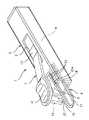
図1は外科用ステープルリムーバの斜視図であり、図2はその縦断面図を示す。上図1において符号1は外科用ステープルリムーバを示す。この外科用ステープルリムーバ1は、主に本体部2と押圧用スライダ3と針受け支持部材4とから構成されている。 FIG. 1 is a perspective view of a surgical staple remover, and FIG. 2 is a longitudinal sectional view thereof. In FIG. 1, reference numeral 1 denotes a surgical staple remover. The surgical staple remover 1 mainly includes a
本体部2は細長の箱形で透明な合成樹脂によって形成されている。本体部2の前端には取込開口部5が形成され、また本体部2の内部には収納部6を構成する空間が形成されている。上記取込開口部5は収納部6に連続している。本体部2の上部中央には、その長手方向に沿ってガイド溝7が形成されている。このガイド溝7の下部にはガイド通路8が形成されている。なお、収納部6は外部から内部を目視できる構成であればよく、必ずしも本体部2を透明にする構成に限定されない。収納部6に内部を覗き込めるようなスリット状の透明窓部を形成する構成であってもよい。 The
押圧用スライダ3はスライダ本体3aと押圧レバー10と針押し部11とから構成されている。スライダ本体3aは上記ガイド通路8に摺動自在に設けられ、バネ12によって常時前方に移動するように付勢されている。スライダ本体3aの上部には凸部13が形成され、この凸部13はガイド溝7に係合し、スライダ本体3aの前後の移動端を規制している。 The
押圧レバー10は、上記凸部13の前端から斜め前方に突出し、その先端上部には指掛け部14が形成されている。押圧レバー10はその基部から下方に曲り変形するように弾性材料によって形成されている。 The
針押し部11は押圧レバー10の前端の指掛け部14の下方に突出形成され、さらにその先端は、前部の係合部15が後部の押圧部16より突出して鉤形に形成されている。なお、針押し部11は強度を要求されるから、金属などの硬質の素材によって構成するのが好ましい。 The
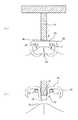
次に、針受け支持部材4は金属によって構成され、前部がU字形に形成された部材で、このU字形の針支持部17の前部から1対の平行な針受け部18が後方に連続形成されている。なお、U字形の針支持部17は図3(a)に示されるように、外科用ステープラによって折り曲げられた外科用ステープル20と皮膚21との間に差し込まれて外科用ステープル20のクラウン部22の両側を下から支持するもので、その幅は上記外科用ステープル20のクラウン部22の幅よりも少し狭い程度に形成され、またクラウン部22と外科用ステープル20との間に差し込みやすいように肉厚も薄く形成されている。 Next, the needle
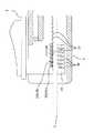
針支持部17は本体部2の収納部6の取込開口部5から前方に突出し、また針受け部18は本体部2の収納部6内に収まるように配置され、適宜手段によって固定されている。また、上記針受け部18には、上記収納部6内において連続する係合凹部23が形成されている。係合凹部23は鋸歯状に形成された歯と歯との間に形成され、前後に隣り合う係合凹部23の間隔は約ステープル1〜1.5本分の幅と略同じ程度になるように設定されている。そして、最も手前(最前部)にある係合凹部23aは、上記押圧用スライダ3が移動端までスライドしたときの係合部15の後面の略直上部にあるように設定されている。さらに、通常の外科手術で使用される外科用ステープルの本数は30〜40本程度であり、上記係合凹部23の数もこれに合わせて決めればよい。 The
次に、上記構成の外科用ステープルリムーバ1の作用について説明する。まず、片手で本体部2を持ち、図3(a)に示されるように、傷口を縫合した外科用ステープルのクラウン部22の下側に針受け支持部材4の針支持部17を入れ、クラウン部22の両側の下部を針支持部17で支持する。次に、押圧用スライダ3の指掛け部14に人差し指の先端を掛けて押圧レバー10を下方に折り曲げる。これにより、針押し部11の押圧部16が外科用ステープルのクラウン部22の上部中央に係合する。さらに、指掛け部14に力を加えて押圧レバー10を下方に曲げると、外科用ステープルのクラウン部22は両側下部が針支持部17で支持された状態で、中央上部が押圧部16によって上から下方に押し込まれるので、図3(b)のようにU字状に折れ曲がって変形し、全体がM字状になって両側の脚部24は皮膚から抜き出される。このようにして外科用ステープル20を抜き出した後、図4に示すように上記押圧用スライダ3をバネ12に抗して後方にスライドさせると、外科用ステープル20は針押し部11の係合部15に係合し、取込開口部5から収納部6内に取り込まれ、さらに押圧用スライダ3の移動端まで送られる。上記押圧用スライダ3が移動端までスライドしたとき、図5のように押圧用スライダ3の係合部15の後面は最も手前にある係合凹部23aに対応する位置にあるように設定されているから、引き込まれた外科用ステープルは最も手前の係合凹部23aに係合して支持される。その後、押圧用スライダ3から力を抜いてバネ12のバネ力によって初期位置に復帰移動させる。押圧用スライダ3が原位置に戻っても、外科用ステープル20は1対の針受け部18に安定して支持され、また両針受け部18の鋸歯状に形成された歯と歯の間に形成された係合凹部23に係合しているので、戻り方向(前方)には移動できず、そのままの位置に保持される。 Next, the operation of the surgical staple remover 1 configured as described above will be described. First, the
次の外科用ステープル20も同様にして押圧用スライダ3の同じ操作によって抜針され、押圧用スライダ3の後方スライドによって取込開口部5から収納部6内に取り込まれる。そして、押圧用スライダ3が移動端に到達したときに、取り込まれた外科用ステープル20は最も手前の係合凹部23aまで押し込まれるので、この係合凹部23aに保持されていた前の外科用ステープル20は強制的に後方に押し出される。係合凹部23の後方には緩やかな傾斜が形成されているので、押された外科用ステープル20は円滑に後方に押し込まれる。隣り合う係合凹部23bの間隔は約ステープル1〜1.5本分の幅と略同じ程度になるように設定されているから、押し込まれた外科用ステープル20は次の係合凹部23bに係合して支持される。その後、押圧用スライダ3から力を抜いてバネ12のバネ力によって初期位置に復帰移動させると、上記2つの係合凹部23に係合した外科用ステープル20は、そのままの位置に保持される。以下、同様にして針受け支持部材4の針受け部18の係合凹部23には、抜針された外科用ステープルが順次に後方に並べられた状態で保持される。 Similarly, the next
このようにして、最後の外科用ステープル20を最も手前の係合凹部23に保持したとき、すべての抜針された外科用ステープル20は針受け部18の係合凹部23に整然と並んだ状態で保持される。したがって、何本の外科用ステープルを抜いたかは、本体部2の横から目視によって数えることができる。 In this way, when the last
なお、収納部6の高さは、抜針された外科用ステープル20の高さよりも少しだけ大きくなるようにするのが好ましい。具体的には、収納部6の上面は、針受け部18に支持された外科用ステープル20よりもその厚み分より少し高くし、また収納部6の下面は、針受け部18に支持された外科用ステープル20の下端よりも僅かに低い程度に形成するのが好ましい。これにより、外科用ステープルリムーバ1を少し傾けたり、動かしたりしても、内部に保持された外科用ステープルは係合凹部23から外れにくく、針受け部18に支持された状態で良好に保持される。 In addition, it is preferable that the height of the storage portion 6 is slightly larger than the height of the
また、係合凹部23は必ずしも鋸歯状に形成されているものに限定されない。例えば、連続する波形でもよい。 Moreover, the engagement recessed
さらに、本体部2又は針受け支持部材4の針受け部18に、10本、20本、30本毎に目安となるように色変えしたり、目盛りを表示したりすることにより、迅速かつ確実に計算できるようにしてもよい。 Further, the
1 外科用ステープルリムーバ
3 押圧用スライダ
4 針受け支持部材
6 収納部
18 針受け部
20 ステープル
23 係合凹部DESCRIPTION OF SYMBOLS 1
Claims (3)
Translated fromJapanese上記収納部の内部を目視可能に形成するとともに、
上記針受け部には、上記押圧用スライダによって引き込まれた外科用ステープルの1本のそれぞれと係合可能な複数の係合凹部を連続的に形成したことを特徴とする外科用ステープルリムーバ。A needle support part that enters the lower part on both sides of the crown part of the surgical staple with the skin stitched and supports the surgical staple; and a central upper part of the crown part of the surgical staple supported by the needle support part. The surgical staple is deformed and extracted from the skin, and a pressing slider for sliding the surgical staple along a pair of parallel needle receiving portions continuously formed from the needle support portion, and the pressing slider is pulled by the pressing slider. A surgical staple remover comprising a storage portion for storing the surgical staples,
While forming the inside of the storage part to be visible,
The surgical staple remover characterized in that a plurality of engaging recesses that can be engaged with each of the surgical staples drawn by the pressing slider are continuously formed in the needle receiving portion.
Priority Applications (6)
| Application Number | Priority Date | Filing Date | Title |
|---|---|---|---|
| JP2006216832AJP4894402B2 (en) | 2006-08-09 | 2006-08-09 | Surgical staple remover |
| TW096128570ATW200814964A (en) | 2006-08-09 | 2007-08-03 | Surgical staple remover |
| US12/376,503US20100228268A1 (en) | 2006-08-09 | 2007-08-03 | Surgical staple remover |
| CNA2007800275267ACN101489493A (en) | 2006-08-09 | 2007-08-03 | Surgical staple remover |
| EP07791922AEP2050400A1 (en) | 2006-08-09 | 2007-08-03 | Surgical staple remover |
| PCT/JP2007/065248WO2008018378A1 (en) | 2006-08-09 | 2007-08-03 | Surgical staple remover |
Applications Claiming Priority (1)
| Application Number | Priority Date | Filing Date | Title |
|---|---|---|---|
| JP2006216832AJP4894402B2 (en) | 2006-08-09 | 2006-08-09 | Surgical staple remover |
Publications (2)
| Publication Number | Publication Date |
|---|---|
| JP2008036265A JP2008036265A (en) | 2008-02-21 |
| JP4894402B2true JP4894402B2 (en) | 2012-03-14 |
Family
ID=39171961
Family Applications (1)
| Application Number | Title | Priority Date | Filing Date |
|---|---|---|---|
| JP2006216832AExpired - Fee RelatedJP4894402B2 (en) | 2006-08-09 | 2006-08-09 | Surgical staple remover |
Country Status (2)
| Country | Link |
|---|---|
| JP (1) | JP4894402B2 (en) |
| CN (1) | CN101489493A (en) |
Families Citing this family (3)
| Publication number | Priority date | Publication date | Assignee | Title |
|---|---|---|---|---|
| JP4814274B2 (en)* | 2008-03-12 | 2011-11-16 | 昌貴 鮒田 | Medical instruments |
| JP5830258B2 (en)* | 2011-03-17 | 2015-12-09 | オリンパス株式会社 | Surgery support system and surgical tool |
| CN106232036B (en)* | 2014-05-13 | 2019-02-12 | 捷锐士阿希迈公司(以奥林巴斯美国外科技术名义) | Lithotrity Medical Devices |
Family Cites Families (5)
| Publication number | Priority date | Publication date | Assignee | Title |
|---|---|---|---|---|
| US4026520A (en)* | 1976-03-05 | 1977-05-31 | Senco Products, Inc. | Surgical staple extractor |
| US4487394A (en)* | 1982-04-14 | 1984-12-11 | Senco Products, Inc. | Extractor for surgical staples |
| JPS59101142A (en)* | 1982-12-02 | 1984-06-11 | 磐田電工株式会社 | Removing device of medical sturing needle, chuck and holder |
| JP4305375B2 (en)* | 2004-12-03 | 2009-07-29 | マックス株式会社 | Surgical staple remover |
| JP4780295B2 (en)* | 2005-01-19 | 2011-09-28 | マックス株式会社 | Medical staples |
- 2006
- 2006-08-09JPJP2006216832Apatent/JP4894402B2/ennot_activeExpired - Fee Related
- 2007
- 2007-08-03CNCNA2007800275267Apatent/CN101489493A/enactivePending
Also Published As
| Publication number | Publication date |
|---|---|
| JP2008036265A (en) | 2008-02-21 |
| CN101489493A (en) | 2009-07-22 |
Similar Documents
| Publication | Publication Date | Title |
|---|---|---|
| JP5021028B2 (en) | Staple device | |
| JP6336694B2 (en) | Staple cartridge with shipping wedge | |
| CN107205748B (en) | Surgical clip applier with multiple clip feed mechanisms | |
| CN104902830B (en) | Safety Cutting Equipment | |
| RU2623130C2 (en) | Linear suturing device | |
| JP4970495B2 (en) | Surgical stapling device | |
| JP4190983B2 (en) | Staple device | |
| JP2006081687A5 (en) | ||
| US20110118758A1 (en) | Multi-fire suturing instrument with proximal ferrule release feature | |
| CN102178551B (en) | Trigging and transmission device for disposable transluminal cutter stapler | |
| JP5371610B2 (en) | Suture device | |
| JP6702879B2 (en) | Device and method for loading sutures | |
| CN204364049U (en) | A kind of nail-head component and chamber mirror surgical operation seaming and cutting device | |
| CN106618655B (en) | Surgical cutting stapler capable of suturing and cutting firstly | |
| JP2004121852A (en) | Apparatus for collecting sample from body | |
| DK163561B (en) | SURGICAL ADAPTER | |
| JP4894402B2 (en) | Surgical staple remover | |
| CN107157538B (en) | Linear cutting anastomat | |
| WO2008018378A1 (en) | Surgical staple remover | |
| JP2007159939A (en) | Holder for scalpel blade | |
| CN105796145A (en) | Nail head assembly and suturing and cutting device for endoscopic surgical operation | |
| JP5050553B2 (en) | Surgical staple remover | |
| CN202740058U (en) | Nail warehouse component and suture instrument with knife using same | |
| JP4305375B2 (en) | Surgical staple remover | |
| CN202113113U (en) | Actuating transmission device of disposable intracavity cutting anastomat |
Legal Events
| Date | Code | Title | Description |
|---|---|---|---|
| A621 | Written request for application examination | Free format text:JAPANESE INTERMEDIATE CODE: A621 Effective date:20090210 | |
| A131 | Notification of reasons for refusal | Free format text:JAPANESE INTERMEDIATE CODE: A131 Effective date:20110726 | |
| A521 | Written amendment | Free format text:JAPANESE INTERMEDIATE CODE: A523 Effective date:20110922 | |
| TRDD | Decision of grant or rejection written | ||
| A01 | Written decision to grant a patent or to grant a registration (utility model) | Free format text:JAPANESE INTERMEDIATE CODE: A01 Effective date:20111129 | |
| A01 | Written decision to grant a patent or to grant a registration (utility model) | Free format text:JAPANESE INTERMEDIATE CODE: A01 | |
| A61 | First payment of annual fees (during grant procedure) | Free format text:JAPANESE INTERMEDIATE CODE: A61 Effective date:20111212 | |
| R150 | Certificate of patent or registration of utility model | Free format text:JAPANESE INTERMEDIATE CODE: R150 | |
| FPAY | Renewal fee payment (event date is renewal date of database) | Free format text:PAYMENT UNTIL: 20150106 Year of fee payment:3 | |
| LAPS | Cancellation because of no payment of annual fees |