JP4894386B2 - Audio signal processing apparatus, audio signal processing method, and audio signal processing program - Google Patents
Audio signal processing apparatus, audio signal processing method, and audio signal processing programDownload PDFInfo
- Publication number
- JP4894386B2 JP4894386B2JP2006199039AJP2006199039AJP4894386B2JP 4894386 B2JP4894386 B2JP 4894386B2JP 2006199039 AJP2006199039 AJP 2006199039AJP 2006199039 AJP2006199039 AJP 2006199039AJP 4894386 B2JP4894386 B2JP 4894386B2
- Authority
- JP
- Japan
- Prior art keywords
- range
- audio signal
- volume
- localization angle
- specified range
- Prior art date
- Legal status (The legal status is an assumption and is not a legal conclusion. Google has not performed a legal analysis and makes no representation as to the accuracy of the status listed.)
- Expired - Fee Related
Links
- 230000005236sound signalEffects0.000titleclaimsdescription203
- 238000003672processing methodMethods0.000titleclaims2
- 230000004807localizationEffects0.000claimsdescription135
- 238000000034methodMethods0.000claimsdescription62
- 230000008569processEffects0.000claimsdescription44
- 238000011835investigationMethods0.000claimsdescription20
- 230000004044responseEffects0.000claimsdescription7
- 238000010586diagramMethods0.000description12
- 230000006870functionEffects0.000description11
- 230000008859changeEffects0.000description5
- 230000003247decreasing effectEffects0.000description3
- 230000006835compressionEffects0.000description2
- 238000007906compressionMethods0.000description2
- 238000005401electroluminescenceMethods0.000description2
- 230000004048modificationEffects0.000description2
- 238000012986modificationMethods0.000description2
- 238000003825pressingMethods0.000description2
- 238000005070samplingMethods0.000description2
- 230000003321amplificationEffects0.000description1
- 238000006243chemical reactionMethods0.000description1
- 230000000994depressogenic effectEffects0.000description1
- 229910003460diamondInorganic materials0.000description1
- 239000010432diamondSubstances0.000description1
- 239000006185dispersionSubstances0.000description1
- 230000000694effectsEffects0.000description1
- 239000004973liquid crystal related substanceSubstances0.000description1
- 238000004519manufacturing processMethods0.000description1
- 238000003199nucleic acid amplification methodMethods0.000description1
- 230000003287optical effectEffects0.000description1
- 230000001172regenerating effectEffects0.000description1
- 239000004065semiconductorSubstances0.000description1
- 238000000926separation methodMethods0.000description1
- 230000000007visual effectEffects0.000description1
Images


Classifications
- H—ELECTRICITY
- H04—ELECTRIC COMMUNICATION TECHNIQUE
- H04S—STEREOPHONIC SYSTEMS
- H04S7/00—Indicating arrangements; Control arrangements, e.g. balance control
- H04S7/40—Visual indication of stereophonic sound image
- H—ELECTRICITY
- H04—ELECTRIC COMMUNICATION TECHNIQUE
- H04S—STEREOPHONIC SYSTEMS
- H04S7/00—Indicating arrangements; Control arrangements, e.g. balance control
- H04S7/30—Control circuits for electronic adaptation of the sound field
- H—ELECTRICITY
- H04—ELECTRIC COMMUNICATION TECHNIQUE
- H04S—STEREOPHONIC SYSTEMS
- H04S2400/00—Details of stereophonic systems covered by H04S but not provided for in its groups
- H04S2400/13—Aspects of volume control, not necessarily automatic, in stereophonic sound systems
Landscapes
- Physics & Mathematics (AREA)
- Engineering & Computer Science (AREA)
- Acoustics & Sound (AREA)
- Signal Processing (AREA)
- Stereophonic System (AREA)
Description
Translated fromJapaneseこの発明は、或る角度に定位している音源の音声信号について音声信号処理を施すための装置、方法、プログラムに関する。 The present invention relates to an apparatus, a method, and a program for performing audio signal processing on an audio signal of a sound source localized at a certain angle.
CD(Compact Disc)やDVD(Digital Versatile Disc)などに収録されるコンテンツや、TV(テレビジョン)放送番組などのコンテンツにおける音声信号には様々な種類の音源が含まれている。例えば、音楽を収録したコンテンツであれば、歌声や楽器の音などといった音源が含まれる。また、TV放送番組としてのコンテンツであれば、出演者の声や効果音、笑い声、拍手などといった音源が含まれる。 Various types of sound sources are included in audio signals in content recorded on CDs (Compact Discs) and DVDs (Digital Versatile Discs) and content such as TV (television) broadcast programs. For example, in the case of content containing music, sound sources such as singing voices and instrument sounds are included. In the case of content as a TV broadcast program, sound sources such as performers' voices, sound effects, laughter, and applause are included.
これらの音源は、収録時には別々のマイクロフォンにより収録することもあるが、その場合においても音声信号自体は最終的には2チャンネル(2ch)や5.1チャンネル(5.1ch)などの予め定められたチャンネル数に絞られることになる。このとき、ミキシング等が行われることで、それぞれの音源がそれぞれ対応する角度に定位するように調整されることになる。なお、この明細書においては、「チャンネル」という文言を上記カッコ内に示したように「ch」と略称して用いる場合がある。 These sound sources may be recorded by separate microphones at the time of recording, but even in that case, the audio signal itself is finally determined in advance such as 2 channels (2 ch) or 5.1 channels (5.1 ch). Will be limited to the number of channels. At this time, by performing mixing or the like, each sound source is adjusted to be localized at a corresponding angle. In this specification, the word “channel” is sometimes abbreviated as “ch” as shown in parentheses.
なお、複数の音源が混合するようにされた音声信号から複数の音源の音声信号を分離して利用できるようにする技術については、以下の特許文献を挙げることができる。
ところで、上述したように、複数の音源が混合するようにされた音声信号を含むコンテンツが、再生装置やTV受像機側などで再生(受信・復調)されると、その再生音声は、これに含まれる複数の音源の音声信号のそれぞれが、収録時に調整するようにされた定位角度を再現したかたちで得られるようになる。 By the way, as described above, when a content including an audio signal in which a plurality of sound sources are mixed is reproduced (received / demodulated) on the reproducing apparatus or the TV receiver side, the reproduced audio is Each of the audio signals of the multiple sound sources included can be obtained in a form that reproduces the localization angle that was adjusted during recording.
しかしながら、ユーザの嗜好などにより、制作側で意図した音源の定位感が受け入れられない場合もある。また、或る角度に定位している或る周波数範囲の音源の音量を抽出する、或る角度に定位している或る周波数範囲の音源の音量を変更するなど、コンテンツの楽しみ方の幅を広げるような工夫も要請される。 However, the sound source localization intended by the production side may not be accepted depending on the user's preference. In addition, the range of how to enjoy content can be expanded, such as extracting the volume of a sound source in a certain frequency range localized at a certain angle or changing the volume of a sound source in a certain frequency range localized at a certain angle. A device that can be expanded is also required.
以上のことにかんがみ、この発明は、複数の音源が混合するようにされた音声信号について、各音源についての情報を視覚を通じて認識できるようにすると共に、各音源を考慮した調整を行えるようにすることを目的とする。 In view of the above, the present invention makes it possible to visually recognize information about each sound source and to make adjustments in consideration of each sound source for an audio signal in which a plurality of sound sources are mixed. For the purpose.
上記課題を解決するため、本発明は、2チャンネル以上の音声信号について、予め決められる各周波数帯域における予め決められる定位角度毎の音量値を調査する調査手段と、前記調査手段からの調査結果に基づいて、周波数と定位角度とを2つの軸とする2次元平面上に、周波数帯域毎であって定位角度毎の音量値を表現する表示データを形成する形成手段とを備えることを特徴とする。
In order to solve the above-mentioned problems, thepresent invention relates to an investigation means for investigating a volume value for each predetermined localization angle in each predetermined frequency band for audio signals of two or more channels, and an investigation result from the investigation means. And forming means for forming display data representing a volume value for each frequency band and for each localization angle on a two-dimensional plane having the frequency and the localization angle as two axes. .
本発明によれば、調査手段により、2チャンネル以上の音声信号について、予め決められる各周波数帯域における予め決められる定位角度毎の音量値(音量の大きさ)が調査される。これにより、周波数帯域毎、定位角度毎に、どのような音量値の音源が存在するのかが把握される。そして、形成手段により、周波数と定位角度とを2つの軸とする2次元平面上に、音量値を表現する表示データが形成される。
According to thepresent invention , the investigation means investigates the volume value (volume level) for each predetermined localization angle in each predetermined frequency band for the audio signals of two or more channels. As a result, it is possible to grasp what sound volume value of the sound source exists for each frequency band and each localization angle. Then, display data representing the volume value is formed on the two-dimensional plane having the frequency and the localization angle as two axes by the forming means.
これにより、形成手段により形成された表示データが用いられて、表示画面上に周波数帯域毎、定位角度毎に、どのような音量値の音源が存在するのかを示す表示を行うことができるようにされ、その状態をユーザが視覚を通じて迅速に認識し、正確に把握することができるようにされる。 As a result, the display data formed by the forming means can be used so that a display showing what sound volume value of the sound source exists for each frequency band and each localization angle on the display screen can be performed. Then, the user can quickly recognize and accurately grasp the state through vision.
さらに、本発明は、前記形成手段からの前記表示データに応じて表示される表示画像を通じて、前記音声信号においての指定範囲を指示するための操作入力を受け付ける指定範囲受付手段と、前記指定範囲受付手段を通じて受け付けた前記操作入力に応じて指定するようにされる前記音声信号においての前記指定範囲内と前記指定範囲外との一方あるいは両方についての音量の調整指示を受け付ける音量指示受付手段と、前記音量指示受付手段を通じて受け付けた前記調整指示に応じて、前記音声信号においての前記指定範囲内と前記指定範囲外との一方あるいは両方の音声信号についての音量調整を行う調整手段とを備え、前記指定範囲受付手段は、前記操作入力による前記2次元平面上の任意の2点の指定により設定される周波数範囲、定位角度範囲を前記指定範囲として受け付ける。
Furthermore, the present invention provides a designated range receiving means for receiving an operation input for designating a designated range in the audio signal through a display image displayed according to the display data from the forming means, and the designated range receiving Volume instruction receiving means for receiving a volume adjustment instruction for one or both of the specified range and the specified range outside the specified range in the audio signal to be specified according to the operation input received through the means; Adjusting means for adjusting the volume of one or both of the audio signal within the specified range and outside the specified range in the audio signal in accordance with the adjustment instruction received through the volume instruction receiving unit, The range receiving means is a frequency range set by specifying any two points on the two-dimensional plane by the operation input, Position accepts the angle range as the designated range.
本発明によれば、任意の指定範囲を設定する指定範囲受付手段により、ユーザからの音声信号においての任意の範囲の指定範囲を指示するための操作入力が受け付けられる。この操作入力は、形成手段により形成された表示データに応じた表示画像を通じて行うようにされる。
According to thepresent invention , the operation input for instructingthe designated range of thearbitrary range in the audio signal from the user is accepted bythe designated range receiving meansfor setting thearbitrary designated range. This operation input is performed through a display image corresponding to the display data formed by the forming means.
また、音量指示受付手段により、前記指定範囲受付手段を通じて受け付けた操作入力に応じて指示するようにされた指定範囲内と指定範囲外の一方または両方について、音量の調整指示が受け付けられる。この音量の調整指示に応じて、調整手段により、指定範囲内の音声信号と指定範囲外の音声信号との一方または両方について、音量が調整される。 Further, the sound volume instruction accepting unit accepts a sound volume adjustment instruction for one or both of the designated range and the outside of the designated range which are designated according to the operation input accepted through the designated range accepting unit. In response to the sound volume adjustment instruction, the adjusting means adjusts the sound volume for one or both of the audio signal within the designated range and the audio signal outside the designated range.
これにより、目的とする音源が存在する範囲を指定範囲として指定して、その指定範囲内の音声信号の音量を大きくしたり、また、指定範囲外の音声信号の音量を大きくして、臨場感を増やすようにしたり、あるいは、指定範囲内の音声信号と指定範囲外の音声信号との両方の音量を調整して、再生対象の音声信号に含まれる目的とする音源に注目して音量値の調整を行えるようにすることによって、再生対象の音声信号の音量を部分的に調整し、ユーザの好みの状態にして再生することができるなど、音量バランスを調整することができるようにされる。 As a result, the range where the target sound source exists is specified as the specified range, and the volume of the audio signal within the specified range is increased, or the volume of the audio signal outside the specified range is increased, so that Or adjust the volume of both the audio signal within the specified range and the audio signal outside the specified range and pay attention to the target sound source included in the audio signal to be played. By making the adjustment possible, the volume balance can be adjusted such that the volume of the audio signal to be reproduced can be partially adjusted and reproduced in the user's preferred state.
この発明によれば、複数の音源が混合するようにされた音声信号について、各音源についての情報を視覚を通じて認識できるようにすることができる。これに基づき、各音源を考慮した音量の調整処理を行うことができ、コンテンツの楽しみ方の幅を広げることができる。 According to the present invention, information about each sound source can be recognized visually through an audio signal in which a plurality of sound sources are mixed. Based on this, it is possible to perform a volume adjustment process in consideration of each sound source, and it is possible to widen the range of contents enjoyment.
以下、図を参照しながら、この発明による装置、方法、プログラムの一実施の形態について説明する。 Hereinafter, an embodiment of an apparatus, a method, and a program according to the present invention will be described with reference to the drawings.
[第1の実施の形態]
以下に説明する第1の実施の形態においては、この発明による装置、方法、プログラムを音声信号の再生装置(以下、単に再生装置という。)に適用した場合を例にして説明する。そして、この第1の実施の形態の再生装置は、以下に詳述するように、複数の音源が混合するようにされた2チャンネル以上の音声信号の各周波数帯域における定位角度毎の音量値を、色の明るさにより各々周波数と定位角度を2つの軸とした2次元平面上に表現する機能を有するものである。[First Embodiment]
In the first embodiment described below, a case where the apparatus, method, and program according to the present invention are applied to an audio signal reproduction apparatus (hereinafter simply referred to as a reproduction apparatus) will be described as an example. Then, as will be described in detail below, the playback device according to the first embodiment obtains a volume value for each localization angle in each frequency band of audio signals of two or more channels mixed with a plurality of sound sources. The function of expressing on a two-dimensional plane with the frequency and localization angle as two axes according to the brightness of the color.
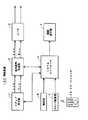
図1は、この第1の実施の形態の再生装置100を説明するためのブロック図である。図1に示すように、この第1の実施の形態の再生装置100は、メディア再生部1、音声信号処理部2、D/Aコンバータ(Digital/Analog Converter)3、システムコントローラ4、操作部5、コマンド受信部6、画面表示部7を備えると共に、リモートコマンダ10を通じて遠隔制御することができるものである。 FIG. 1 is a block diagram for explaining the reproducing apparatus 100 according to the first embodiment. As shown in FIG. 1, a playback apparatus 100 according to the first embodiment includes a
メディア再生部1は、例えばCD(Compact Disc)やDVD(Digital Versatile Disc)、或いはブルーレイディスク(Blu-Ray Disc)などの光ディスク記録媒体や、MD(Mini Disc(登録商標))などの光磁気ディスク、ハードディスクなどの磁気ディスク、半導体メモリを内蔵した記録媒体など、所要の記録媒体に記録されている音声信号を読み出して再生することができるものである。 The
この場合、メディア再生部1が対応する記録媒体には、Lch(左チャンネル)とRch(右チャンネル)とによる2系統の音声信号によるコンテンツが記録されているものとする。メディア再生部1で再生されたこれらLch、Rchの音声信号は、音声信号処理部2に供給される。 In this case, it is assumed that content based on two audio signals of Lch (left channel) and Rch (right channel) is recorded on the recording medium supported by the
音声信号処理部2は、メディア再生部1からのLchとRchとの音声信号について、予め決められる各周波数帯域における定位角度毎の音量値を調査し、その調査結果を後述するシステムコントローラ4へと供給する。また、音声信号処理部2は、LchとRchの音声信号を、再生用の音声信号Lexと音声信号Rexとして、D/Aコンバータ3に供給する。 The audio
なお、音声信号処理部2において用いることが可能な、2chの音声信号から各周波数帯域における定位角度毎の音量値を調査する方法としては種々のものが知られているが、例えば、先に提出した特願2005−327237(整理番号0590529003)の手法を用いることが可能である。 Various methods for investigating the volume value for each localization angle in each frequency band from 2ch audio signals that can be used in the audio
上記の特願2005−327237では、音声信号を周波数帯域分割処理により所定の周波数帯域毎に分割し(例えば、11Hz幅で、4000周波数帯域に分割し)、各々周波数帯域分割された音声信号の定位角度を調査することにより、或る角度に定位している音源の音声信号のみを抽出する、或いは消す、或いは音量を調整するなど、定位角度ごとに音源の調整を行う手法を提案した。この手法を用いる事で各周波数帯域における定位角度毎の音量値を調査する事が可能となる。 In the above Japanese Patent Application No. 2005-327237, the audio signal is divided into predetermined frequency bands by frequency band division processing (for example, divided into 4000 frequency bands with a width of 11 Hz), and localization of the audio signals divided into the respective frequency bands is performed. By investigating the angle, we proposed a method of adjusting the sound source for each localization angle, such as extracting, erasing, or adjusting the volume of the sound source of the sound source localized at a certain angle. By using this method, the volume value for each localization angle in each frequency band can be investigated.
音声信号処理部2からD/Aコンバータ3に供給さされた音声信号Lex、Rexは、D/Aコンバータ3にてD/A変換が施され、アナログ信号とされたLchの音声信号、Rchの音声信号として出力される。 The audio signals Lex and Rex supplied from the audio
システムコントローラ4は、図示しないが、CPU(Central Processing Unit)、ROM(Read Only Memory)、RAM(Random Access Memory)、EEPROM(Electrically Erasable and Programmable ROM)などの不揮発性メモリがCPUバスを通じて接続されて形成されたマイクロコンピュータであり、この第1の実施の形態の再生装置100の各部を制御するものである。 Although not shown, the
システムコントローラ4に対しては、図1に示したように、操作部5とコマンド受信部6と画面表示部7とが接続されている。操作部5は、当該再生装置100の筐体外部に表出するようにして設けられた各種の操作子を備え、それらに対するユーザからの操作入力を受け付けて、受け付けた操作入力に応じたコマンド信号を形成し、これをシステムコントローラ4に供給することができるものである。 As shown in FIG. 1, an
また、コマンド受信部6は、リモートコマンダ10から発せられた例えば赤外線信号等に依るコマンド信号を受信し、これを電気信号に変換して、システムコントローラ4に供給する。リモートコマンダ10上にも各種の操作子が設けられており、上述したように、コマンド受信部6は、これらリモートコマンダ10上の操作子の操作に応じた赤外線などのコマンド信号を電気信号に変換してシステムコントローラ4に供給する。 In addition, the
システムコントローラ4は、操作部5またはコマンド受信部6からのコマンド信号に応じて、この第1の実施の形態の再生装置100の各部を制御する。これによって再生装置100ではユーザの操作入力に応じた動作が実行するようにされる。例えば、操作部5やリモートコマンダ10にはメディア再生部1に装填された記録媒体に記録されているコンテンツについての再生指示を行うための操作子が備えられており、当該操作子に対する操作に応じたコマンド信号が入力されることに応じて、システムコントローラ4はメディア再生部1を制御してコンテンツの再生処理を開始させることができる。 The
さらに、この第1の実施の形態のシステムコントローラ4は、上述したように、音声信号処理部2からの予め決められる各周波数帯域における定位角度毎の音量値の調査結果に基づいて、再生対象の音声信号に含まれる各音源についての情報を画面表示部7の表示画面に表示させるためのデータを生成し、これを画面表示部7に供給する。 Furthermore, as described above, the
画面表示部7は、例えば、LCD(Liquid Crystal Display)、有機EL(Electro Luminescence)パネル、PDP(Plasma Display Panel)、CRT(Cathode Ray Tube)などの表示素子とそのコントロール回路とを備え、システムコントローラ4からの表示データの供給を受けて、これに応じて画像を表示素子の表示画面に表示させることができるものである。 The
したがって、この第1の実施の形態の再生装置100は、操作部5やリモートコマンダ10とコマンド受信部6を通じてメディア再生部1に装填された記録媒体に記録されている音声信号の再生が指示された場合には、システムコントローラ4は、メディア再生部1を制御して、目的とする音声信号を記録媒体から読み出し、音声信号処理部2、D/Aコンバータ3を通じて再生するようにする。 Therefore, the reproduction apparatus 100 according to the first embodiment is instructed to reproduce the audio signal recorded on the recording medium loaded in the
そして、同時に、システムコントローラ4は、音声信号処理部2からの予め決められる各周波数帯域における定位角度毎の音量値の調査結果に基づいて、再生対象の音声信号に含まれる各音源についての情報を表示させるためのデータを形成し、これを画面表示部7に供給することにより、再生対象の音声信号に含まれる各音源についての情報を画面表示部7の表示画面に表示させることができるようにしている。 At the same time, the
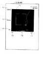
図2は、画面表示部7の表示画面に表示される再生対象の音声信号に含まれる各音源についての情報の表示例を説明するための図であり、具体的には、予め決められた各周波数帯域における定位角度毎に存在する音源についての音量値を色の明るさで表した場合の例である。そして、図2において、外枠は、画面表示部7の表示画面7Gを示している。そして、表示画面7Gには、再生対象の音声信号に含まれる各音源についての情報の表示領域である音量表示部71が設けられる。 FIG. 2 is a diagram for explaining a display example of information about each sound source included in the audio signal to be reproduced displayed on the display screen of the
この第1の実施の形態において、画面表示部7の表示画面7Gに表示される音量表示部71は、図2に示すように、横軸が各音源の音像の定位角度を、縦軸は周波数をそれぞれ示している。この第1の実施の形態においては、横軸の定位角度は、中央を0°(0度)として、左右に60°(60度)づつの120°(120度)の範囲を持っている。また、縦軸の周波数は、0Hz〜8000Hzの範囲を持っている。 In the first embodiment, as shown in FIG. 2, the
そして、図2に示した例の場合、音量表示部71において黒色の領域は音量が小さい成分の部分であり、白色の領域は音量が大きい成分の部分である。また、音量表示部71において、上述もしたように、横軸は定位角度を表しており、左側に定位している音源の音声信号の音量値を左側に、右側に定位している音源の音声信号の音量値を右側に、中央に定位している音源の音声信号の音量値を中央に表すようにしている。また、音量表示部71において、上述もしたように、縦軸は周波数を表しており、高周波帯域の音量値を上側に、低周波帯域の音量値を下側に、中周波帯域の音量値を中央に表すようにしている。 In the case of the example shown in FIG. 2, in the
したがって、音量表示部71において、右下の領域は右側に定位している低周波帯域の音量値を表す。すなわち、音量表示部71において、横軸および縦軸および色の明るさという3つの要素を用いて定位角度および周波数および音量値の3つの成分を表している。また図2において、表示72、73、74は、対応する周波数の値を示し、表示75、76、77は、対応する定位角度の値を表している。 Therefore, in the
そして、図2の例の場合には、「0°」を中心にして、左右に60°(±60°)の範囲であって、周波数が4000Hz以下の部分に、より特徴的には、左右に30°(±30°)の範囲であって、周波数が2000Hz以下の部分に、音量値の大きな音源が存在していることが分かる。 In the case of the example in FIG. 2, a range of 60 ° (± 60 °) left and right with “0 °” as the center and a frequency of 4000 Hz or less, more characteristically, left and right It can be seen that there is a sound source having a large volume value in a portion of 30 ° (± 30 °) and having a frequency of 2000 Hz or less.
次に、この発明による第1の実施の形態のソフトウェアでの実装例について説明する。図3は、この発明による第1の実施の形態の再生装置100で行われる処理を説明するためのフローチャートであり、この発明をソフトウェアで実現するようにした場合の例にも対応するものである。 Next, an implementation example in software of the first embodiment according to the present invention will be described. FIG. 3 is a flowchart for explaining processing performed by the playback apparatus 100 according to the first embodiment of the present invention, and corresponds to an example in which the present invention is realized by software. .
図3に示す処理は、操作部5やリモートコマンダ10及びコマンド受信部6を通じて音声信号の再生指示を受け付け、メディア再生部1に装填された記録媒体に記録されている音声信号を再生するようにした場合に、音声信号処理部2とシステムコントローラ4と画面表示部7とが協働して実行する処理である。 The process shown in FIG. 3 receives an audio signal reproduction instruction through the
まず、再生装置100のシステムコントローラ4は、音声信号処理部2を制御して、再生対象の音声信号が、自機において処理可能な信号形式であるか否かを判定する(ステップS101)。例えば、再生対象の音声信号がMP3(MPEG-1 Audio Layer 3)等の圧縮方式によって圧縮された信号である場合や、想定している信号フォーマットのサンプリング周波数と異なるような場合には、そのままの信号形式では処理を実行することが出来ないので、処理可能な信号フォーマットに変換するようにしている。 First, the
すなわち、ステップS101の判断処理において、肯定結果が得られると次のステップS103へ移るのに対し、ステップS101の判断処理において、否定結果が得られると、このことは音声信号処理部2が再生対象の音声信号に対して処理を実行することができないことを示しているので、ステップS102の処理に移ることになる。 In other words, if a positive result is obtained in the determination process in step S101, the process proceeds to the next step S103. If a negative result is obtained in the determination process in step S101, this means that the audio
したがって、ステップS101の判断処理において、再生対象の音声信号が自機においてそのまま処理可能な信号形式のものではないと判断したときには、システムコントローラ4は、音声信号処理部2を制御して、再生対象の音声信号を処理可能な信号形式の音声信号に変換する(ステップS102)。 Therefore, when it is determined in step S101 that the audio signal to be reproduced is not in a signal format that can be directly processed by the own device, the
ステップS102の処理の後には、または、ステップS101の判断処理において、再生対象の音声信号が自機においてそのまま処理可能な信号形式のものであると判断した場合には、システムコントローラ4は、音声信号処理部2を制御して、再生対象の音声信号から各周波数帯域における定位角度毎の音量値を調査するようにすると共に、再生対象の音声信号をD/Aコンバータ3に供給して再生するようにする(ステップS103)。 After the process of step S102, or in the determination process of step S101, if it is determined that the audio signal to be reproduced has a signal format that can be processed as it is by the own device, the
この後、システムコントローラ4は、音声信号処理部2から、再生対象の音声信号についての各周波数帯域における定位角度毎の音量値の調査結果に基づいて、再生対象の音声信号に含まれる各音源についての情報を表示させるためのデータを形成し、これを画面表示部7に供給し、画面表示部7の表示画面7Gに表示される再生対象の音声信号に含まれる各音源についての情報を更新する(ステップS104)。 Thereafter, the
そして、システムコントローラ4は、続いて音声信号処理部2に入力される次の音声信号信号が存在するか否かを判定する(ステップS105)。ステップS105の判断処理において肯定結果が得られた場合、このことは次に処理を行うべき音声信号が存在することを表しており、システムコントローラ4は、再度、ステップS101からの処理を繰り返すようにする。また、ステップS105の判断処理において否定結果が得られた場合、処理を行うべき対象が存在しないため、システムコントローラ4は、この図3に示した処理を終了する。 Then, the
このように、この第1の実施の形態の再生装置100は、2チャンネル以上の音声信号の各周波数帯域における定位角度毎の音量値を、色の明るさにより各々周波数と定位角度を2つの軸とした2次元平面上に表現する機能を実現することができる。このように、2チャンネル以上の音声信号の各周波数帯域における定位角度毎の音量値を、色の明るさにより各々周波数と定位角度を2つの軸とした2次元平面上に表現することにより、再生している音声信号の特性が容易に分かるようになる。 As described above, the reproducing apparatus 100 according to the first embodiment uses two axes for the volume value for each localization angle in each frequency band of audio signals of two or more channels, and for each frequency and localization angle according to color brightness. The function to express on the two-dimensional plane can be realized. In this way, by reproducing the sound volume value for each localization angle in each frequency band of an audio signal of two or more channels on the two-dimensional plane with the frequency and the localization angle as two axes according to the brightness of the color, reproduction is performed. This makes it easier to understand the characteristics of the audio signal being played.
[第2の実施の形態]
次に、第2の実施の形態について説明する。この第2の実施の形態においても、上述した第1の実施の形態の場合と同様に、この発明による装置、方法、プログラムを音声信号の再生装置に適用した場合を例にして説明する。そして、以下に説明する第2の実施の形態の再生装置200は、第1の実施の形態の再生装置100を応用し、ユーザ操作により特定の周波数範囲および定位角度範囲を選択し、選択した範囲内と選択された範囲外との一方あるいは両方の音量値を調整することにより、音量バランスを調整することができるようにしたものである。[Second Embodiment]
Next, a second embodiment will be described. In the second embodiment as well, as in the case of the first embodiment described above, the case where the apparatus, method, and program according to the present invention are applied to an audio signal reproducing apparatus will be described as an example. Then, the
図4は、この第2の実施の形態の再生装置200を説明するためのブロック図である。なお、この図4において、図1を用いて説明した第1の実施の形態の再生装置100と同様に構成される部分には、同じ参照符号を付し、その部分の説明については省略する。したがって、図4と図1とを比較すると分かるように、図4に示した第2の実施の形態の再生装置200と図1に示した第1の実施の形態の再生装置100とで異なる点は、音声信号処理部8とシステムコントローラ9との機能である。 FIG. 4 is a block diagram for explaining the reproducing
そして、この第2の実施の形態の再生装置200においても、図1を用いて説明した第1の実施の形態の再生装置100の場合と同様に、メディア再生部1で再生するようにされたLch(左チャンネル)の音声信号とRch(右チャンネル)の音声信号とは、音声信号処理部8に供給される。 Also in the
音声信号処理部8は、メディア再生部1からのLchの音声信号とRchの音声信号と、後述するシステムコントローラ9からの周波数範囲および定位角度範囲指示信号S1および音量バランス指示信号S2との供給を受けて、Lchの音声信号とRchの音声信号とに含まれる、指示された周波数範囲および定位角度範囲内の音源の音声信号に対して、音量バランス指示信号より決定されたゲインを乗じ、また、指示された周波数範囲および定位角度範囲外の音源の音声信号について音量バランス指示信号より決定されたゲインを乗ずるように構成したものである。 The audio
このように、音声信号処理部8は、再生対象の音声信号の指示された範囲の範囲内と範囲外とに対して、それぞれについて指示するようにされたゲインを乗じ、周波数と、定位角度とによって規定される範囲でゲインを調整したLchの音声信号とRchの音声信号とを出力することができるようにしたものである。 In this way, the audio
そして、音声信号処理部8は、さらに、上述したようにゲインを乗じた音声信号に応じて、各周波数帯域における定位角度毎の音量値を調査し、後述するシステムコントローラ9へと供給する。この各周波数帯域における定位角度毎の音量値の調査は、上述した第1の実施の形態の再生装置100の音声信号処理部2と同様にして行われる。 Then, the audio
このようにゲイン調整などの音声信号処理が施されたLchの音声信号と、Rchの音声信号とは、音声信号Lex、音声信号Rexとして、音声信号処理部8からD/Aコンバータ3に供給される。D/Aコンバータ3は、これに供給された音声信号Lex、音声信号RexをD/A変換することによりアナログ信号とされたLchの音声信号とRchの音声とを形成し、これらを出力する。 The Lch audio signal and the Rch audio signal subjected to audio signal processing such as gain adjustment in this way are supplied from the audio
また、システムコントローラ9は、上述したように、音声信号処理部8から供給される、ゲイン調整後の再生対象の音声信号についての各周波数帯域における定位角度毎の音量値の調査結果の供給を受けて、この調査結果に基づいて、ゲイン調整後の再生対象の音声信号に含まれる各音源についての情報を画面表示部7の表示画面に表示させるためのデータを生成し、これを画面表示部7に供給する。 Further, as described above, the system controller 9 receives the supply of the investigation result of the volume value for each localization angle in each frequency band for the audio signal to be reproduced after gain adjustment supplied from the audio
このゲイン調整後の再生対象の音声信号に含まれる各音源についての情報を表示するためのデータの生成処理は、図1を用いて説明した第1の実施の形態のシステムコントローラ4の場合と同様に行われる処理である。これにより、この第2の実施の形態の再生装置200の場合にも、ゲイン調整後の再生対象の音声信号に含まれる各音源についての情報を画面表示部7の表示画面に表示することができるようにされる。 Data generation processing for displaying information about each sound source included in the audio signal to be reproduced after gain adjustment is the same as in the
そして、この第2の実施の形態の再生装置200のシステムコントローラ9は、上述もしたように、使用者からの操作入力に応じて、周波数範囲および定位角度範囲指示信号S1と、音量バランス指示信号S2とを形成し、これらの指示信号S1、S2を音声信号処理部8に供給することができるものである。 Then, as described above, the system controller 9 of the
システムコントローラ9は、使用者からの操作入力を、操作部5を通じて、あるいは、リモートコマンダ10とコマンド受信部6とを通じて受け付けることが可能であるが、ここでは、使用者からの操作入力をリモートコマンダ10とコマンド受信部6とを通じて受け付ける場合を例にして説明する。 The system controller 9 can accept an operation input from the user through the
図5は、この第2の実施の形態の再生装置200のリモートコマンダ10の外観の一例を説明するための図である。リモートコマンダ10上には、例えば、図5に示したように、方向指示のための操作子および決定のための操作子が備えられている。つまり、図5に示したように、右方向キー10a、左方向キー10b、上方向キー10c、下方向キー10dがカーソルの移動方向を示すなど、方向指示のための操作子であり、実行キー10eが処理の実行を指示する決定のための操作子である。これ以外にも種々のファンクションキーなどからなる操作キー群10fが設けられている。 FIG. 5 is a diagram for explaining an example of the appearance of the
この第2の実施の形態の再生装置200においては、使用者は、画面表示部7の表示画面7Gに表示される音源についての情報の表示を確認しながら、リモートコマンダ10に設けられている方向指示のための操作子10a、10b、10c、10dや決定のための操作子10eを用いて、周波数範囲および定位角度範囲を指示すると共に、音量バランスを指示する。 In the
システムコントローラ9は、これらの指示を受け付けて、受け付けた指示に応じて周波数範囲および定位角度範囲指示信号S1と、音量バランス指示信号S2とを生成し、これらを音声信号処理部8に供給する。これにより、音声信号処理部8においては、指示された周波数範囲および定位角度範囲内の音源の音声信号に対して、音量バランス指示信号S2より決定されたゲインを乗じ、また、指示された周波数範囲および定位角度範囲外の音源の音声信号について音量バランス指示信号より決定されたゲインを乗じ、使用者の指示に応じてゲイン調整した音声信号を再生することができるようにしている。 The system controller 9 receives these instructions, generates a frequency range and localization angle range instruction signal S1 and a volume balance instruction signal S2 according to the received instructions, and supplies these to the audio
以下、音量バランスを変化させる周波数範囲および定位角度範囲を設定する手順と、指定の範囲内および指定の範囲外の音量バランスを変更する手順とを、リモートコマンダ10に対する操作と、これに応じて変化する画面表示部7の表示画面7Gの表示画像とを対応付けながら詳細に説明する。 Hereinafter, the procedure for setting the frequency range and the localization angle range for changing the volume balance and the procedure for changing the volume balance within the specified range and outside the specified range will be changed according to the operation on the
図6は、この第2の実施の形態の再生装置200において、メディア再生部1に装填された記録媒体に記録されている音声信号を再生するようにした場合において、音声信号処理部8の調査結果に基づいて、システムコントローラ9が画面表示部7の表示画面7Gに表示させるようにする表示画像の表示例を説明するための図である。 FIG. 6 shows an investigation of the audio
図6に示す表示例は、基本的に図2を用いて説明した第1の実施の形態の再生装置100において、音声信号の再生中に画面表示部7の表示画面7Gに表示される表示画像と同様のものである。このため、図6において、図2に示した部分と同様に構成される部分については、同じ参照符号を付し、その部分の詳細な説明については省略する。 The display example shown in FIG. 6 is basically the display image displayed on the display screen 7G of the
そして、この第2の実施の形態の再生装置200においても、画面表示部7の表示画面7Gに表示される音量表示部71は、図6に示すように、横軸が各音源の音像の定位角度を、縦軸は周波数を示している。この第2の実施の形態においても、横軸の定位角度は、中央を0°(0度)として、左右に60°(60度)づつの120°(120度)の範囲を持っている。また、縦軸の周波数は、0Hz〜8000Hzの範囲を持っている。 Also in the
そして、図6においても、音量表示部71は、図2に示した音量表示部71の場合と同様に、音量の大きさを色の明るさで示す。すなわち、横軸および縦軸および色の明るさという3つの要素を用いて定位角度および周波数および音量値の3つの成分を表している。さらに、この第2の実施の形態の再生装置200の場合、音量表示部71においては、リモートコマンダ10により指定された周波数範囲および定位角度範囲を表示することにより、ある範囲の音量バランスを変化させる際に手助けとなるようにしている。 Also in FIG. 6, the
すなわち、この第2の実施の形態の再生装置200のユーザは、図5を用いて説明したように、再生装置200のリモートコマンダ10に設けられている右方向キー10a、左方向キー10b、上方向キー10c、下方向キー10d、実行キー10eなどの操作子を操作することにより、再生装置1に対し音量バランスを変化させる周波数範囲および定位角度範囲を設定し、それぞれの音量バランスを変更することができる。 That is, as described with reference to FIG. 5, the user of the
図7、図8は、周波数範囲および定位角度範囲を指定する場合においての表示画像の表示例を説明するための図である。以下においては、図7、図8をも参照して具体的に説明する。 7 and 8 are diagrams for explaining display examples of display images when a frequency range and a localization angle range are designated. Below, it demonstrates concretely also with reference to FIG. 7, FIG.
まず、第一段階として、所定の操作を行うことにより、図7に示すように、開始点、終了点を指示するためのポインタ(指示子)Pを表示させ、右方向キー10a、左方向キー10b、上方向キー10c、下方向キー10dを操作して、選択する周波数範囲および定位角度範囲の開始点Sとなるべき位置にポインタPを位置付け、実行キー10eを押下することにより、開始点Sを決定する。 First, as a first stage, by performing a predetermined operation, as shown in FIG. 7, a pointer (indicator) P for indicating a start point and an end point is displayed, and a right direction key 10a, a left direction key 10b, up key 10c, down key 10d, the pointer P is positioned at the position to be the start point S of the frequency range and localization angle range to be selected, and the start point S is depressed by pressing the execution key 10e. To decide.
すなわち、右方向キー10aを操作することにより定位角度範囲の開始点Sを右方向に移動し、左方向キー10bを操作することにより定位角度範囲の開始点Sを左方向に移動し、上方向キー10cを操作することにより周波数範囲の開始点Sを高周波帯域方向に移動し、下方向キー10dを操作することにより周波数範囲の開始点Sを低周波帯域方向に移動し、実行キー10eを操作することにより周波数範囲および定位角度範囲の開始点Sを設定する。 That is, the start point S of the localization angle range is moved to the right by operating the right direction key 10a, and the start point S of the localization angle range is moved to the left by operating the left direction key 10b. By operating the key 10c, the start point S of the frequency range is moved in the high frequency band direction, and by operating the down key 10d, the start point S of the frequency range is moved in the low frequency band direction, and the execution key 10e is operated. Thus, the start point S of the frequency range and the localization angle range is set.
このように、現在位置を示すポインタPを、音量表示部71の表示領域上に重ねて表示することで開始点Sの指示をしやすくすることができるのである。 As described above, the pointer P indicating the current position is displayed so as to overlap the display area of the
そして、開始点Sを決定した後、第二段階として、さらに右方向キー10a、左方向キー10b、上方向キー10c、下方向キー10dを操作することにより、図8に示すように、ポインタPを移動させることにより、選択する定位角度範囲および周波数範囲の終了点Eを指示し、実行キー10eを操作しその終了点Eを決定する。 Then, after the start point S is determined, as a second step, the pointer P is operated as shown in FIG. 8 by further operating the right direction key 10a, the left direction key 10b, the up direction key 10c, and the down direction key 10d. Is moved to indicate the end point E of the selected localization angle range and frequency range, and the execution key 10e is operated to determine the end point E.
すなわち、右方向キー10aを操作することにより定位角度範囲の終了点Eを右方向に移動し、左方向キー10bを操作することにより定位角度範囲の終了点Eを左方向に移動し、上方向キー10cを操作することにより周波数範囲の終了点Eを高周波帯域方向に移動し、下方向キー10dを操作することにより周波数範囲の終了点Eを低周波帯域方向に移動し、実行キー10eを操作することにより周波数範囲および定位角度範囲の終了点Eを設定する。 That is, the end point E of the localization angle range is moved to the right by operating the right direction key 10a, and the end point E of the localization angle range is moved to the left by operating the left direction key 10b. By operating the key 10c, the end point E of the frequency range is moved in the high frequency band direction, and by operating the down key 10d, the end point E of the frequency range is moved in the low frequency band direction, and the execution key 10e is operated. Thus, the end point E of the frequency range and the localization angle range is set.
この際、システムコントローラ9が使用者からの指示入力に応じて表示データを形成し、これを画面表示部7に供給することにより、図8に示すように、選択した開始点Sおよび指示している終了点Eを対角線上の頂点とした長方形を音量表示部71上に重ねて表示することにより、指示するようにしている定位角度範囲および周波数範囲を視覚を通じて認識できるようにしている。さらに、システムコントローラ9が、音声信号処理部8を制御して、指示された範囲内の音源の音声信号のみを出力するようにすることにより、指示するようにしている定位角度範囲および周波数範囲を聴覚を通じて認識できるようにしている。これらにより、ユーザが行う終了点Eの指示をしやすくすることができる。 At this time, the system controller 9 generates display data in response to an instruction input from the user, and supplies the display data to the
上述のようにして、周波数範囲および定位角度範囲の開始点および終了点を設定した後、第三段階として、これら開始点S、終了点Eを対角線上の頂点とした長方形で囲まれた範囲内とその範囲外の音量バランスを、リモートコマンダ10の上方向キー10c、下方向キー10dを操作することにより変化させる。 After setting the start point and end point of the frequency range and the localization angle range as described above, as a third step, within the range surrounded by a rectangle with the start point S and end point E as diagonal vertices The volume balance outside the range is changed by operating the up key 10c and down key 10d of the
具体的には、上方向キー10cを操作することにより開始点S、終了点Eで指定された範囲内の音源の音量を大きくし、さらに指定された範囲外の音源の音量を小さくしたり、これとは逆に、下方向キー10dを操作することにより開始点S、終了点Eで指定された範囲内の音源の音量を小さくし、さらに指定された範囲外の音源の音量を大きくしたりすることができる。 Specifically, by operating the up direction key 10c, the volume of the sound source within the range specified by the start point S and the end point E is increased, and the volume of the sound source outside the specified range is further decreased, On the other hand, by operating the down key 10d, the volume of the sound source within the range specified by the start point S and the end point E is decreased, and the volume of the sound source outside the specified range is increased. can do.
また、開始点S、終了点Eで指定された範囲内と範囲外の何れか一方を選択し、その選択した範囲の音声信号について音量を大きくしたり、あるいは、小さくしたりすることもできる。すなわち、開始点S、終了点Eで指定された範囲内と範囲外との両方について音量調整を行うのではなく、何れか一方の範囲だけについて音量調整を行うようにすることもできる。 In addition, any one of the range specified by the start point S and the end point E and the range outside the range can be selected, and the volume of the audio signal in the selected range can be increased or decreased. That is, it is also possible to adjust the volume only for one of the ranges, instead of adjusting the volume for both the range designated by the start point S and the end point E and the range outside the range.
また、開始点S、終了点Eで指定された範囲内と範囲外との音量バランスを指示することにより、開始点S、終了点Eで指定された範囲内と範囲外とのそれぞれの音声信号に対して乗算するゲイン値を設定し、これを用いて当該範囲内と範囲外との音量調整(音量バランスの調整を行うようにすることもできる。 Further, by instructing the volume balance between the range specified by the start point S and the end point E and the range outside the range, the respective audio signals within and outside the range specified by the start point S and the end point E are indicated. It is also possible to set a gain value to be multiplied with respect to and adjust the volume (adjustment of the volume balance) within the range and outside the range by using this gain value.
以上説明したように、第一段階から第三段階までの一連の操作を行う事により、この第2の実施の形態の再生装置のユーザは、特定の周波数範囲および定位角度範囲を選択し、その選択範囲内と選択範囲外との音量バランスを調整する機能を操作することが可能となる。すなわち、特定の周波数範囲および定位角度範囲を選択し、その選択範囲内と選択範囲外と一方あるいは両方の音量調整を行うことにより、両範囲の音量バランスを調整することができる。 As described above, by performing a series of operations from the first stage to the third stage, the user of the playback device of the second embodiment selects a specific frequency range and localization angle range, and It is possible to operate a function for adjusting the volume balance between the selection range and the outside of the selection range. That is, by selecting a specific frequency range and localization angle range and adjusting the volume of one or both of the selected range and the outside of the selected range, the volume balance of both ranges can be adjusted.
次に、この発明による第2の実施の形態のソフトウェアでの実装例について説明する。図9、図10は、この発明による第2の実施の形態の再生装置100で行われる処理を説明するためのフローチャートであり、この発明をソフトウェアで実現するようにした場合の例にも対応するものである。 Next, a software implementation example of the second embodiment according to the present invention will be described. FIGS. 9 and 10 are flowcharts for explaining the processing performed by the playback apparatus 100 according to the second embodiment of the present invention, and also corresponds to an example in which the present invention is realized by software. Is.
図9、図10に示す処理は、例えば、リモートコマンダ10及びコマンド信号受信部6を通じて音声信号の再生指示を受け付け、メディア再生部1に装填された記録媒体に記録されている音声信号を再生するようにした場合に、音声信号処理部8とシステムコントローラ9と画面表示部7とが協働して実行する処理である。 The processing shown in FIGS. 9 and 10 receives, for example, an audio signal reproduction instruction through the
まず、再生装置200のシステムコントローラ9は、上述した第1の実施の形態の再生装置100の場合と同様に、音声信号処理部8を制御して、再生対象の音声信号が、自機において処理可能な信号形式であるか否かを判定する(ステップS201)。例えば、再生対象の音声信号がMP3(MPEG-1 Audio Layer 3)等の圧縮方式によって圧縮された信号である場合や、想定している信号フォーマットのサンプリング周波数と異なるような場合には、そのままの信号形式では処理を実行することが出来ないので、処理可能な信号フォーマットに変換するようにしている。 First, the system controller 9 of the
すなわち、ステップS201の判断処理において、肯定結果が得られると次のステップS203へ移るのに対し、ステップS201の判断処理において、否定結果が得られると、このことは音声信号処理部8が再生対象の音声信号に対して処理を実行することができないことを示しているので、ステップS202の処理に移ることになる。 That is, if a positive result is obtained in the determination process in step S201, the process proceeds to the next step S203. If a negative result is obtained in the determination process in step S201, this means that the audio
したがって、ステップS201の判断処理において、再生対象の音声信号が自機においてそのまま処理可能な信号形式のものではないと判断したときには、システムコントローラ9は、音声信号処理部8を制御して、再生対象の音声信号を処理可能な信号形式の音声信号に変換する(ステップS202)。 Accordingly, when it is determined in step S201 that the audio signal to be reproduced is not in a signal format that can be directly processed by the own device, the system controller 9 controls the audio
ステップS202の処理の後には、または、ステップS201の判断処理において、再生対象の音声信号が自機においてそのまま処理可能な信号形式のものであると判断した場合には、システムコントローラ9は、リモートコマンダ10及びコマンド受信部6を通じて、ユーザによる音量バランスを調整する範囲の開始点Sの設定操作を受け付けている最中か否か、すなわち、開始点設定中か否かを判断する(ステップS203)。 After the process of step S202, or in the determination process of step S201, if it is determined that the audio signal to be reproduced has a signal format that can be processed as it is by the own device, the system controller 9 10 and the
ステップS203の判断処理において、開始点設定中であると判断したときには、システムコントローラ9は、コマンド受信部6を通じて受け付けるリモートコマンダ10からのコマンド信号に応じて、内部に保持するようにしている開始点Sの位置(位置情報)を更新し、これに応じてポインタPの表示位置を変更するようにするデータを形成し、これを画面表示部7に供給することによりポインタPの表示位置を変更する(ステップS204)。この後、システムコントローラ9は、後述する図10のステップS209の処理に進む。 When determining that the start point is being set in the determination process of step S203, the system controller 9 stores the start point in accordance with a command signal from the
なお、ステップS204の処理において、リモートコマンダ10から実行キー10eが押下操作されたことを示すコマンド信号が送信されてきたときには、そのときのポインタPの位置が、開始点Sとして設定するようにされ、終了点Eの設定操作を受け付けることができるようにされる。また、リモートコマンダ10から実行キー10eが押下操作されたことを示すコマンド信号が送信されてくるまでは、開始点Sの設定操作が繰り返し行うようにされる。 In the process of step S204, when a command signal indicating that the execution key 10e has been pressed is transmitted from the
また、ステップS203の判断処理において、開始点設定中ではないと判断したときには、システムコントローラ9は、リモートコマンダ10及びコマンド受信部6を通じて、ユーザから音量バランスを調整する範囲の終了点Eの設定操作を受け付けている最中か否か、すなわち、終了点設定中か否かを判断する(ステップS205)。 When determining that the start point is not being set in the determination process of step S203, the system controller 9 sets the end point E of the range for adjusting the volume balance from the user through the
ステップS205の判断処理において、終了点設定中であると判断したときには、システムコントローラ9は、コマンド受信部6を通じて受け付けるリモートコマンダ10からのコマンド信号に応じて、終了点Eの位置を更新し、これに応じてポインタPの表示位置を変更するようにするデータを形成し、これを画面表示部7に供給することによりポインタPの表示位置を変更する(ステップS206)。この後、システムコントローラ9は、後述する図10のステップS209の処理に進む。 If it is determined in step S205 that the end point is being set, the system controller 9 updates the position of the end point E according to the command signal from the
なお、ステップS206の処理において、リモートコマンダ10から実行キー10eが押下操作されたことを示すコマンド信号が送信されてきたときには、そのときのポインタPの位置が、終了点Eとして設定するようにされ、ゲイン値の変更操作を受け付けることができるようにされる。また、開始点Sの設定後においては、リモートコマンダ10から実行キー10eが押下操作されたことを示すコマンド信号が送信されてくるまでは、終了点Eの設定操作が繰り返し行うようにされる。 In the process of step S206, when a command signal indicating that the execution key 10e has been pressed is transmitted from the
また、ステップS205の判断処理において、終了点設定中ではないと判断したときには、システムコントローラ9は、リモートコマンダ10及びコマンド受信部6を通じて、ユーザからの音声バランスの調整操作を受け付けたか否か、すなわち、音声バランスが変化したか否かを判断する(ステップS207)。 If it is determined in step S205 that the end point is not being set, the system controller 9 has received a voice balance adjustment operation from the user through the
ステップS207の判断処理において、音声バランスが変化したと判断したときには、システムコントローラ9は、コマンド受信部6を通じて受け付けるリモートコマンダ10からのコマンド信号に応じて、指定された範囲内、範囲外の音声信号に対する内部に保持している音声バランス値を更新する(ステップS208)。この後、システムコントローラ9は、後述する図10のステップS209の処理に進む。 When it is determined in step S207 that the sound balance has changed, the system controller 9 determines whether the sound signal is within or outside the specified range according to the command signal from the
なお、ステップS208の処理において、リモートコマンダ10から実行キー10eが押下操作されたことを示すコマンド信号が送信されてきたときには、変更するようにされた音声バランス値が決定値として設定するようにされる。また、終了点Sの設定後においては、リモートコマンダ10から実行キー10eが押下操作されたことを示すコマンド信号が送信されてくるまでは、音声バランス値の設定操作が繰り返し行うようにされる。 In the process of step S208, when a command signal indicating that the execution key 10e has been pressed is transmitted from the
また、ステップS207の判断処理において、音声バランスが変化していないと判断した場合、また、上述もしたように、ステップS204、ステップS206、ステップS208の各処理の後においては、システムコントローラ9は、図10に示すステップS209の処理に進む。 If it is determined in step S207 that the sound balance has not changed, and as described above, after each of steps S204, S206, and S208, the system controller 9 The process proceeds to step S209 shown in FIG.
そして、システムコントローラ9は、音声信号処理部8を制御して、各々オーディオ信号から、ユーザ操作に拠り指定された周波数範囲および定位角度範囲内の音源の音声信号については、ユーザ操作に拠り設定された音量バランス設定値から決定したゲイン値を乗じ、ユーザ操作に拠り設定された周波数範囲および定位角度範囲外の音源の音声信号については、ユーザ操作に拠り設定された音量バランス設定値から決定したゲイン値を乗じて、各周波数帯域における定位角度毎の音量値を調査するようにし、ゲイン調整後の再生対象の音声信号をD/Aコンバータ3に供給して再生するようにする(ステップS209)。 Then, the system controller 9 controls the audio
この後、システムコントローラ9は、音声信号処理部8から、再生対象の音声信号についての各周波数帯域における定位角度毎の音量値の調査結果に基づいて、再生対象の音声信号に含まれる各音源についての情報を表示させるためのデータを形成し、これを画面表示部7に供給し、画面表示部7の表示画面に表示される再生対象の音声信号に含まれる各音源についての情報を更新する(ステップS210)。 After that, the system controller 9 determines, for each sound source included in the audio signal to be reproduced, from the audio
そして、システムコントローラ9は、続いて音声信号処理部8に入力される次の音声信号信号が存在するか否かを判定する(ステップS211)。ステップS211の判断処理において肯定結果が得られた場合、このことは次に処理を行うべき音声信号が存在することを表しており、システムコントローラ9は、再度、ステップS201からの処理を繰り返すようにする。また、ステップS211の判断処理において否定結果が得られた場合、処理を行うべき対象が存在しないため、システムコントローラ9は、この図9、図10に示した処理を終了する。 Then, the system controller 9 determines whether or not there is a next audio signal signal that is subsequently input to the audio signal processing unit 8 (step S211). If a positive result is obtained in the determination process in step S211, this means that there is an audio signal to be processed next, and the system controller 9 repeats the process from step S201 again. To do. If a negative result is obtained in the determination process in step S211, there is no target to be processed, and the system controller 9 ends the processes shown in FIGS.
このように、この第2の実施の形態の再生装置200は、第1の実施の形態の再生装置100の場合と同様に、2チャンネル以上の音声信号の各周波数帯域における定位角度毎の音量値を、色の明るさにより各々周波数と定位角度を2つの軸とした2次元平面上に表現する機能を実現することができる。そして、2次元平面において、ユーザ操作により特定の範囲を選択し、選択範囲内および選択範囲外の音量バランスを調整する機能を実現している。 As described above, the
このように、ユーザ操作により特定の周波数範囲および特定の定位角度範囲を選択し、選択範囲内および選択範囲外の音量バランスを調整できる。したがって、再生対象の音声信号が音楽の音声信号である場合には、目的とする楽器の音を目立たせるようにしたり、歌声を目立たせ、演奏を控えめにしたりするというように、コンテンツの楽しみ方の幅を広げることができる。 In this manner, a specific frequency range and a specific localization angle range can be selected by a user operation, and the volume balance within and outside the selection range can be adjusted. Therefore, when the audio signal to be played is a music audio signal, the way to enjoy the content, such as making the sound of the target instrument stand out, making the singing voice stand out, and conservative performance Can be widened.
[第2の実施の形態の変形例]
上述した第2の実施の形態の再生装置200においては、リモートコマンダ10を通じて周波数範囲および定位角度範囲の設定を行うものとした。しかしこれに限るものではない。例えば、画面表示部7の表示画面7Gにタッチパネル機能を持たせる事により、より容易に設定を行うようにすることができる。[Modification of Second Embodiment]
In the
図11は、表示画面7Gにタッチパネルが貼付された画面表示部7の当該表示画面7Gに表示される画面例を説明するための図である。図11に示すように、画面表示部7の表示画面7Gの前面には、タッチパネル7TPが貼付され、表示画面7Gに表示される画像とタッチパネル7TPとによって、ユーザからの操作入力を受け付ける受付手段としての機能を実現している。 FIG. 11 is a diagram for explaining a screen example displayed on the display screen 7G of the
すなわち、システムコントローラ9は、表示画面7Gのどの位置にどのような表示画像を表示するようにしているかを把握している。また、タッチパネル7TPへのタッチペンや指などによる接触が行われると、タッチパネル7TPは、接触位置を示す座標データを電気信号としてシステムコントローラ9に供給する。また、いわゆるドラッグ操作(引きずり操作)が行われた場合には、刻々と変化する接触位置を示す座標データをタッチパネル7TPは電気信号としてシステムコントローラ9に供給する。 That is, the system controller 9 knows what display image is to be displayed at which position on the display screen 7G. When touch panel 7TP is touched with a touch pen or a finger, touch panel 7TP supplies coordinate data indicating the contact position to system controller 9 as an electrical signal. When a so-called drag operation (drag operation) is performed, the touch panel 7TP supplies coordinate data indicating a contact position that changes every moment as an electrical signal to the system controller 9.
システムコントローラ9は、タッチパネル7TPからの座標データと、その座標データによって示される表示画面7G上の位置に表示されている画像情報とに基づいて、実行するべき処理を決定し、その決定した処理を実行することができるようにしている。このようなタッチパネル7TPに対する操作によって、周波数範囲および定位角度範囲を指定し、さらに音量バランスを変換させるようにする場合について具体的に説明する。 The system controller 9 determines the process to be executed based on the coordinate data from the touch panel 7TP and the image information displayed at the position on the display screen 7G indicated by the coordinate data, and the determined process is performed. To be able to run. The case where the frequency range and the localization angle range are designated by the operation on the touch panel 7TP and the volume balance is further converted will be specifically described.
この第2の実施の形態の変形例の場合においても、画面表示部7の表示画面7Gには、再生対象の音声信号に含まれる各音源についての情報の表示領域である音量表示部71が設けられる。図11において、表示72、73、74は、対応する周波数の値を示し、表示75、76、77は、対応する定位角度の値を表している。 Also in the case of the modification of the second embodiment, the display screen 7G of the
すなわち、この音量表示領域71には、図2、図6に示した音量表示領域71の場合と同様に、横軸が各音源の音像の定位角度を、縦軸は周波数を示し、各音源の音量の大きさを色の明るさで示すようにしている。したがって、横軸および縦軸および色の明るさという3つの要素を用いて、定位角度および周波数および音量値の3つの成分を表している。 That is, in the
また、音量表示部71上に貼付されたタッチパネル7TPに対して、タッチペンや指などを接触させて移動させる操作を行うことによって、周波数範囲および定位角度範囲を指定することができるようにしている。すなわち、ユーザが音量表示部71上に貼付されたタッチパネル7TP上の一点にタッチペンや指などを接触させ、接触させたままの状態で接触位置を別の一点に移動し、接触を解放する。 In addition, the frequency range and the localization angle range can be specified by performing an operation of moving the touch panel 7TP attached on the
このようないわゆるドラッグ・アンド・ドロップ(Drag and Drop)操作を行うことにより、システムコントローラ9は、タッチパネル7TPからの座標データと、対応する表示情報とに基づいて、最初にタッチペンなどを接触させた点を開始点S、最後にタッチペンなどの接触を解放した点を終了点Eとし、その開始点Sおよび終了点Eを対角線上の頂点とした長方形の内部を指定の範囲とすることで音量バランスを変更する周波数範囲および定位角度範囲を設定することができる。 By performing such a so-called drag and drop operation, the system controller 9 first touches the touch pen or the like based on the coordinate data from the touch panel 7TP and the corresponding display information. The volume balance is achieved by setting the start point S and the point where the touch pen or the like is finally released as the end point E, and the inside of the rectangle having the start point S and the end point E as the diagonal vertices within the specified range. A frequency range and a localization angle range can be set.
また、図11において、スライダー701、ボタン702およびボタン703の各表示は音量表示部71に表示する周波数の範囲を変更するためのものである。すなわち、ユーザがスライダー701の部位のうち、現在のスライダーの位置よりも上側の部位に触れるとスライダー701の位置が上側に変化し、その位置の変化に合わせて音量表示部71に表示される周波数の範囲が上側にずれる。 In FIG. 11, each display of the
例えば、図11に示したように、スライダー701の位置が中心にあった場合に表示する周波数の範囲が0Hzから8000Hzまでの範囲であった場合に、スライダー701の位置を全体の1/4(4分の1)ほど上側にずらせば、システムコントローラ9は、音量表示部71の周波数範囲を、2000Hzから10000Hzまでの範囲にずらすといった具合である。 For example, as shown in FIG. 11, when the range of the frequency to be displayed when the position of the
また、ユーザが、タッチペンや指などでボタン702の表示上のタッチパネル7TPに触れた場合には、音量表示部71に表示する周波数の範囲が狭くなる。例えば、図11に示したように、表示する周波数の範囲が0Hzから8000Hzまでの範囲であった場合に、ユーザが、タッチペンや指などでボタン702の表示上のタッチパネル7TPに触れた場合には、システムコントローラ9は、音量表示部71の周波数範囲を、0Hzから4000Hzまでの範囲に狭くするといった具合である。 In addition, when the user touches the touch panel 7TP on the display of the
また、ユーザが、タッチペンや指などでボタン703の表示上のタッチパネル7TPに触れた場合には、音量表示部71に表示する周波数の範囲が拡がる。例えば、図11に示したように、表示する周波数の範囲が0Hzから8000Hzまでの範囲であった場合に、ユーザが、タッチペンや指などでボタン703の表示上のタッチパネル7TPに触れた場合には、システムコントローラ9は、音量表示部71の周波数範囲を、0Hzから16000Hzまでの範囲に拡げるといった具合である。 In addition, when the user touches the touch panel 7TP on the display of the
このようにしてスライダー701、ボタン702およびボタン703を用いて音量表示部71に表示する周波数の範囲を変更できる。なお、ユーザ操作により周波数の範囲が変更された際、表示72、73、74の周波数の値も変更するようにされる。 In this way, the range of frequencies displayed on the
また、図11において、スライダー704、ボタン705およびボタン706の各表示は音量表示部71に表示する定位角度の範囲を変更するためのものである。すなわち、ユーザがスライダー704の部位のうち、現在のスライダーの位置よりも左側の部位に触れるとスライダーの位置が左側に変化し、その位置の変化に合わせて音量表示部71に表示する定位角度の範囲が左側にずれる。 In FIG. 11, each display of the
例えば、図11に示したように、スライダー704の位置が中心にあった場合に表示する定位角度の範囲が−60°から+60°までの範囲であった場合に、スライダー704の位置を全体の1/4(4分の1)ほど左側にずらせば、システムコントローラ9は、音量表示部71の定位角度の範囲を、−90°から+30°までの範囲にずらすといった具合である。 For example, as shown in FIG. 11, when the range of the localization angle displayed when the position of the
また、ユーザが、タッチペンや指などでボタン705の表示上のタッチパネル7TPに触れた場合には、音量表示部71に表示する定位角度の範囲が狭くなる。例えば、図11に示したように、表示する定位角度の範囲が−60°から+60°までの範囲であった場合に、ユーザが、タッチペンや指などでボタン705の表示上のタッチパネル7TPに触れた場合には、システムコントローラ9は、音量表示部71の定位角度の範囲を、−30°から+30°までの範囲に狭くするといった具合である。 In addition, when the user touches the touch panel 7TP on the display of the
また、ユーザが、タッチペンや指などでボタン706の表示上のタッチパネル7TPに触れた場合には、音量表示部71に表示する定位角度の範囲が拡がる。例えば、図11に示したように、表示する定位角度の範囲が−60°から+60°までの範囲であった場合に、ユーザが、タッチペンや指などでボタン706の表示上のタッチパネル7TPに触れた場合には、システムコントローラ9は、音量表示部71の定位角度の範囲を、−120°から+120°までの範囲に拡げるといった具合である。 In addition, when the user touches the touch panel 7TP on the display of the
このようにしてスライダー704、ボタン705およびボタン706を用いて音量表示部71に表示する定位角度の範囲を変更できる。なお、ユーザ操作により定位角度が変更された際、表示75、76、77の定位角度の値も変更するようにされる。 In this manner, the range of the localization angle displayed on the
また、図11において、スライダー708は、ユーザ操作により指定された周波数範囲および定位角度範囲内のゲイン値を設定するためのものである。すなわち、ユーザがスライダー708の部位のうち、現在のスライダーの位置よりも上側の部位に触れるとスライダー708の位置が上側に変化し、その位置の変化に合わせて指定範囲内のゲイン値が増加する。 In FIG. 11, a
例えば、図11に示したように、スライダー708の位置が、変更可能な範囲の中心にあった場合、この場合のゲイン値が0dBであとすると、スライダー708の位置を全体の1/4(4分の1)ほど上側に変化させると、システムコントローラ9は、指定された周波数範囲および定位角度範囲内のゲイン値を+5dBに増加させることになる。 For example, as shown in FIG. 11, when the position of the
また、図11において、スライダー709は、ユーザ操作により指定された周波数範囲および定位角度範囲外のゲイン値を設定するためのものである。すなわち、ユーザがスライダー709の部位のうち、現在のスライダーの位置よりも上側の部位に触れるとスライダー709の位置が上側に変化し、その位置の変化に合わせて指定範囲外のゲイン値が増加する。 In FIG. 11, a
例えば、図11に示したように、スライダー709の位置が、変更可能な範囲の中心にあった場合、この場合のゲイン値が0dBであとすると、スライダー709の位置を全体の1/4(4分の1)ほど上側に変化させると、システムコントローラ9は、指定された周波数範囲および定位角度範囲外のゲイン値を+5dBに増加させることになる。 For example, as shown in FIG. 11, when the position of the
このように、この上述した第1の実施の形態の再生装置100は、2チャンネル以上の音声信号の各周波数帯域における定位角度毎の音量値を、色の明るさにより各々周波数と定位角度を二つの軸としたニ次元平面上に表現することができるものである。そして、上述した第2の実施の形態の再生装置は、第1の実施の形態の再生装置をさらに発展させ、ユーザ操作により特定の範囲を選択し、選択範囲内および選択範囲外の音量バランスを調整する機能を有するようにしたものである。 As described above, the playback apparatus 100 according to the first embodiment described above uses the volume value for each localization angle in each frequency band of the audio signal of two or more channels, and the frequency and localization angle in accordance with the brightness of the color. It can be expressed on a two-dimensional plane with two axes. The playback device of the second embodiment described above further develops the playback device of the first embodiment, selects a specific range by a user operation, and adjusts the volume balance within and outside the selection range. It has a function to adjust.
[他の実施の形態]
なお、上述した第1、第2の実施の形態においては、再生対象の音声信号は、LchとRchの2chの音声信号としたが、これに限るものではない。2ch以上の音声信号にも対応することもできる。具体的には、4ch、5ch、5.1ch、7.1ch、9.1chなどの種々のマルチチャンネルの音声信号を処理対象とする場合にこの発明を適用することができる。[Other embodiments]
In the first and second embodiments described above, the audio signal to be reproduced is a 2-channel audio signal of Lch and Rch, but is not limited thereto. It can also handle audio signals of 2ch or more. Specifically, the present invention can be applied to a case where various multi-channel audio signals such as 4ch, 5ch, 5.1ch, 7.1ch, 9.1ch and the like are to be processed.
また、上述した第1、第2の実施の形態においては、メディア再生部1としては、記録媒体から音声信号(および映像信号)を再生するものとして説明したが、これに限るものではない。メディア再生部1に変えて、AM(Amplitude Modulation)放送信号、FM(Frequency Modulation)放送信号、テレビジョン放送信号、衛星放送信号等の種々の放送信号などを受信・復調して音声信号(および映像信号)を出力するチューナ装置を用いた構成の再生装置にもこの発明を適用することができる。 In the first and second embodiments described above, the
或いは、メディア再生部1やチューナ装置を備えた再生装置ではなく、例えばアンプ装置などとして、外部で再生(受信)された音声信号の供給を受けて、この入力音声信号に対して音声信号処理を行うようにする音声信号処理装置に対して、この発明を適用することももちろん可能である。 Alternatively, instead of the playback device including the
また、上述した第1、第2の実施の形態においては、画面表示部7の表示画面7Gに表示する音量表示部71には、音量の大きさが大きいほど白色になり、音量の大きさが小さいほど黒色になるよう表示させたが、逆の場合であってもよい。すなわち、音量が大きい場合に黒色になり音量が小さい場合に白色になるといった形態である。 In the first and second embodiments described above, the
また、画面表示部7の表示画面7Gに表示する音量表示部71への表示は、カラー表示であってもよい。例えば、予め決められた周波数帯域毎や定位角度の範囲毎に表示色を変えるようにし、色が濃いほど音量レベルは大きく、色が薄いほど音量レベルは低いといったように表したり、逆に、色が薄いほど音量レベルは大きく、色が濃いほど音量レベルは低いといったように表したりすることもできる。 The display on the
また、画面表示部7の表示画面7Gに表示する音量表示部71への表示は、音量の大きさを色で表すだけではなく3次元形式により表示してもよい。また、平面画面に表示するのではなく立体画面に3次元により表現してもよい。また、縦軸と横軸の表現が逆であっても良い。すなわち、縦軸を定位角度、横軸を周波数としてもよい。 In addition, the display on the
また、第2の実施の形態においては、リモートコマンダ10の右方向キー10a、左方向キー10b、上方向キー10c、下方向キー10d、実行キー10eを操作することにより、ある周波数範囲および定位角度範囲を選択し、選択範囲内および選択範囲外の音量バランスを調整できるようにしたが、これ以外の手順、およびこれ以外の方式で範囲の指定をしても良い。また、マウス、タッチパネルなどリモートコマンダ以外の操作機器やポインティングデバイスを用いて範囲の指定を行っても良い。 In the second embodiment, a certain frequency range and localization angle are obtained by operating the right key 10a, the left key 10b, the up key 10c, the down key 10d, and the execution key 10e of the
例えば、マウスであればマウスボタンを押下することにより開始点を設定し、そのまま押下しながらドラッグ(マウスの操作を行いマウスカーソルの位置を移動する)して終了点まで移動し、マウスボタンを解放することにより終了点を設定するとしてもよい。また、ある周波数範囲および定位角度範囲を設定する際に開始点および終了点を対角線上の頂点とする長方形としたが、円や楕円などの形状とし、その内側の範囲を目的とする指定範囲とするようにすることもできる。 For example, in the case of a mouse, the start point is set by pressing the mouse button, and dragging while moving the mouse (moving the mouse cursor by operating the mouse) to move to the end point and releasing the mouse button By doing so, the end point may be set. In addition, when setting a certain frequency range and localization angle range, it is a rectangle with the start point and end point as vertices on the diagonal line, but it has a shape such as a circle or an ellipse, You can also do it.
また、周波数範囲および定位角度範囲を設定する際に、開始点を中心とし終了点を半径とする円の形状の内側を指定範囲としても良い。また、ある周波数範囲および定位角度範囲を設定する際に、ユーザがマウスやタッチパネルなどで描いた閉曲線の内側を目的とする指定範囲としても良い。すなわち、範囲を指定する事が可能な手順、方式、機器であればどのような形態であってもよい。 Further, when setting the frequency range and the localization angle range, the inside of the shape of a circle having the start point as the center and the end point as the radius may be set as the designated range. Moreover, when setting a certain frequency range and localization angle range, it is good also as the designated range aiming at the inside of the closed curve which the user drew with the mouse | mouth, the touch panel, etc. In other words, any form may be used as long as it is a procedure, method, and device that can specify a range.
また、第2の実施の形態においては、選択可能な周波数範囲および定位角度範囲を1つのみとしたが、この選択範囲を複数とし、それぞれの音量バランスを変更する形態であってもよい。 Further, in the second embodiment, only one frequency range and localization angle range that can be selected are used. However, a plurality of the selection ranges may be used, and the respective volume balances may be changed.
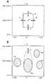
図12、図13は、周波数範囲および定位角度範囲を設定する他の例について説明するための図である。図12Aの場合には、例えば、ポインティングデバイスにより、1つの点xを指定すると、その点xを中心として、定位角度範囲、周波数範囲を予め決められた分だけ確保して、周波数範囲および定位角度範囲を設定するようにする。 12 and 13 are diagrams for explaining another example of setting the frequency range and the localization angle range. In the case of FIG. 12A, for example, when one point x is specified by a pointing device, a localization angle range and a frequency range are secured by a predetermined amount around the point x, and the frequency range and localization angle are secured. Try to set the range.
図12Aの場合には、最初に指定された点xを中心にして、定位角度範囲を左右に10°ずつ取り、周波数範囲を上下に2000Hzづつとって、図12Aに示したように、長方形の範囲Xを自動的に設定するようにする。この範囲Xは、例えば、図12Aにおいて、矢印a、b、c、dが示すように、4辺のそれぞれを移動させ、縮小したり、拡大したりすることができるようにされる。また、1辺を移動させることにより、これに連動して他の3辺も移動させ4辺を一度に調整して、4方に縮小したり、拡大したりするようにすることも可能である。 In the case of FIG. 12A, the localization angle range is 10 ° left and right around the point x specified first, and the frequency range is 2000 Hz up and down. As shown in FIG. The range X is automatically set. For example, the range X can be reduced or enlarged by moving each of the four sides as indicated by arrows a, b, c, and d in FIG. 12A. In addition, by moving one side, the other three sides can be moved in conjunction with this, and the four sides can be adjusted at once to reduce or enlarge in four directions. .
また、図12Bの場合には、1つの点を指定することにより設定される最初の範囲(初期範囲)を楕円によって形成するようにした場合の例である。この図12Bの例の場合にも、図12Aに示した例の場合と同様に、一点xを指定することにより、その点xを中心として例えば縦長の楕円の範囲を設定し、この範囲を図12Bにおいて矢印eが示すように、拡大したり、逆に縮小したりすることができるようにされる。 In the case of FIG. 12B, the first range (initial range) set by designating one point is an ellipse. In the example of FIG. 12B as well, in the same way as in the example shown in FIG. 12A, by designating a single point x, for example, a range of a vertically long ellipse is set around the point x. As indicated by an arrow e in 12B, it can be enlarged or conversely reduced.
ここでは、楕円により周波数範囲および定位角度範囲を設定するようにしたが、これに限るものではない。上述もしたように、円を用いたり、あるいは、半円を用いたり、その他の種々の形状の範囲を指定して、その範囲を変形することにより、ユーザが目的とする範囲を指定するようにすることが可能である。 Here, the frequency range and the localization angle range are set by an ellipse, but the present invention is not limited to this. As described above, a user can specify a target range by using a circle, using a semicircle, or specifying a range of various other shapes and modifying the range. Is possible.
また、図12Bにおいて、範囲71a、71b、71c、71dが示すように、複数の分離角度範囲(周波数範囲および定位角度範囲)を設定するようにすることも可能である。この場合には、指定された範囲71a、71b、71c、71dのそれぞれと、それ以外の部分との音量レベルを指定するようにすることにより、各指定された範囲71a、71b、71c、71dのそれぞれと、それ以外の部分との音量レベルを調整することができる。 In addition, in FIG. 12B, a plurality of separation angle ranges (frequency range and localization angle range) can be set as indicated by
具体的には、範囲71a、71b、71c、71dに対応する楽器の音声信号の音量レベルを大きくし、それ以外の楽器やノイズ音を小さくするなどのことができるようにされる。もちろん、これとは逆に、指定された範囲71a、71b、71c、71dのそれぞれの音源の音量レベルを小さくし、それ以外の部分の音源の音量レベルを大きくするというように調整することも可能である。 Specifically, the volume level of the sound signal of the musical instrument corresponding to the
すなわち、音声コンテンツに含まれる各音源に散らばりに対応して、目的とする音源が属する範囲を設定し、音量レベルを調整することができる。さらに換言すれば、どのような範囲(周波数範囲や音像の定位角度範囲、あるいは、その両方によって特定される範囲)に存在する音源の音声信号について、どのようにレベル調整するかを決めて、これに応じて調整することができる。 That is, the range to which the target sound source belongs can be set and the volume level can be adjusted in correspondence with the dispersion of the sound sources included in the audio content. In other words, it is possible to determine how to adjust the level of the sound signal of the sound source that exists in the range (the range specified by the frequency range and the localization angle range of the sound image, or both). Can be adjusted according to.
また、図13に示すように、音量表示部71自体の形状を扇型とするようにしてもよい。この場合、図13Aに示すように、扇型の開き角を定位角度範囲に一致させ、また、円弧の両端の半径部分における当該半径方向を周波数範囲とすることで、音声信号に含まれる目的とする音源の位置を、扇型の中心αを聴取者の位置に見立て、より直感的に分かりやすい態様で示すようにすることができる。 Moreover, as shown in FIG. 13, the shape of the
そして、例えば、聴取者の左側に音像が定位している音源が属する範囲を指定する場合には、例えば、図13Bに示すように、中心から左側の目的とする部分に範囲71eを設定し、この範囲を縮小したり、拡大したり、また、その位置を変更したりすることにより、目的とする音源の属する周波数範囲および定位角度範囲を設定するようにすることができる。もちろん、音量表示部71の形状は、四角形や扇形に限るものではなく、円、楕円、ひし形、台形など種々の形状とすることが可能である。 For example, when designating a range to which a sound source with a localized sound image belongs to the left side of the listener, for example, as shown in FIG. 13B, a range 71e is set in a target portion on the left side from the center, The frequency range and localization angle range to which the target sound source belongs can be set by reducing, expanding, or changing the position of this range. Of course, the shape of the
また、第2の実施の形態においては、ある周波数範囲および定位角度範囲内と選択範囲外の音量バランスを変更できるとしたが、これ以外の信号処理であってもよく、例えば選択範囲内の音源のみについて、その定位位置を視聴者に近づくように信号処理を施す、指定範囲内の音源を別の場所に定位するよう移動するように信号処理を施す、などのような音声信号処理を施すようにすることも可能である。 In the second embodiment, the volume balance within a certain frequency range and localization angle range and outside the selection range can be changed. However, other signal processing may be used, for example, a sound source within the selection range. For example, the signal processing is performed so that the localization position is closer to the viewer, the signal source is moved so that the sound source within the specified range is localized, and the audio signal processing is performed. It is also possible to make it.
また、各実施の形態において、各々の楽器の周波数特性や倍音成分などから楽器を判別し、楽器の画像や名称を画面表示部7の音量表示部71などに表示してもよい。 In each embodiment, the musical instrument may be determined from the frequency characteristics and harmonic components of each musical instrument, and the image and name of the musical instrument may be displayed on the
また、この発明は、上述もしたように、音声信号の再生装置の他、放送信号の受信復調機能を備えた受信装置、音楽や映像などの再生機能を備えたパーソナルコンピュータ、音声信号の供給を受けて増幅処理等の音声信号処理を行うパワーアンプ装置などの音声信号処理装置等、音声信号や、同期を取って再生すべき音声信号と映像信号とからなるいわゆるAV(Audio/Visual)信号等からなるコンテンツ信号を処理する種々の電子機器に適用することができる。 In addition, as described above, the present invention provides a receiving apparatus having a broadcast signal receiving / demodulating function, a personal computer having a reproducing function for music, video, and the like, as well as an audio signal reproducing apparatus, and an audio signal supply. An audio signal processing apparatus such as a power amplifier apparatus that receives and processes an audio signal such as an amplification process, an audio signal, a so-called AV (Audio / Visual) signal composed of an audio signal and a video signal to be reproduced in synchronization, etc. The present invention can be applied to various electronic devices that process content signals consisting of:
また、図3や図9及び図10のフローチャートを用いて説明した処理を実行するプログラム(ソフトウェア)を形成し、これをコンテンツ信号を処理する種々の電子機器に搭載することにより、この発明により実現される機能を比較的に容易に搭載することができる。 In addition, the present invention is realized by forming a program (software) for executing the processing described with reference to the flowcharts of FIGS. 3, 9, and 10 and mounting the program (software) on various electronic devices for processing content signals. Can be mounted relatively easily.
また、上述したように指定される周波数範囲および定位角度範囲と、その範囲内と範囲外の一方または両方についてのゲイン値または音量バランスを示す情報と、また、処理対象のコンテンツの識別IDとを関連付けて、例えば、システムコントローラ9内のメモリに記憶保持させておくことにより、そのコンテンツが再生される場合には、必ず、指定された指定範囲内と指定範囲外との一方または両方について、指定されたように音声信号のゲイン調整(音量バランスの調整)を行って、ユーザの好みの態様で再生できるようにすることもできる。 In addition, the frequency range and localization angle range specified as described above, information indicating the gain value or volume balance for one or both of the range and the outside of the range, and the identification ID of the content to be processed In association, for example, when the content is played back by being stored in the memory in the system controller 9, it is always specified for one or both of the specified range and the specified range. As described above, the gain of the audio signal (volume balance adjustment) can be adjusted so that it can be reproduced in the user's preferred mode.
また、上述したように指定される周波数範囲および定位角度範囲と、その範囲内と範囲外の一方または両方についてのゲイン値または音量バランスを示す情報とを、例えば、システムコントローラ9内のメモリに記憶保持させておき、種々の音声信号を処理する場合においては、その記憶保持されている情報に基づいて、同じ信号処理を行って、いつでも、どのようなコンテンツでも、ユーザが記憶保持するようにした情報に基づいて、ゲイン調整(音量バランスの調整)を行って、ユーザの好みの態様で再生できるようにすることも可能である。 Further, the frequency range and localization angle range specified as described above, and information indicating the gain value or the volume balance for one or both of the range and the outside of the range are stored in, for example, a memory in the system controller 9. When processing various audio signals, the same signal processing is performed based on the stored information so that the user can store any content anytime. Based on the information, it is possible to perform gain adjustment (adjustment of sound volume balance) so that reproduction can be performed in the user's preferred mode.
また、再生するコンテンツに合わせて、複数の周波数範囲および定位角度範囲と、その範囲内と範囲外の一方または両方についてのゲイン値または音量バランスを示す情報とを、例えば、システムコントローラ9内のメモリに記憶保持しておくことにより、再生されるコンテンツに対応して、いつでもユーザが好みの音量値の態様でコンテンツを再生するなどすることができる。 Further, in accordance with the content to be reproduced, a plurality of frequency ranges and localization angle ranges, and information indicating gain values or volume balances for one or both of the ranges and the ranges are stored in, for example, a memory in the system controller 9 By storing and storing the content, the user can always play back the content in the form of the preferred volume value in accordance with the content to be played back.
また、音声信号などのコンテンツデータに対して、指定された周波数範囲および定位角度範囲と、その範囲内と範囲外の一方または両方についてのゲイン値または音量バランスを示す情報とを付加して、例えば、他の機器などに提供した場合には、当該他の機器においても、その指定された周波数範囲および定位角度範囲と、その範囲内と範囲外の一方または両方についてのゲイン値とに基づいて、コンテンツを再生することもができるようにされる。 Further, for content data such as an audio signal, a specified frequency range and localization angle range and information indicating a gain value or volume balance for one or both of the range and the outside of the range are added. , When provided to other devices, the other devices also, based on the specified frequency range and localization angle range, and the gain value for one or both of the range and the outside of the range, The content can also be played back.
また、音声信号などのコンテンツデータに対して、指定された周波数範囲および定位角度範囲と、その範囲内と範囲外の一方または両方についてのゲイン値または音量バランスを示す情報とを、コンテンツデータの全体に適用したり、あるいは、コンテンツデータの所定の一部分のみに適用したりすることも可能である。 Also, for content data such as audio signals, the specified frequency range and localization angle range, and information indicating the gain value or volume balance for one or both of the range and the outside of the range, Or can be applied to only a predetermined part of the content data.
この場合には、例えば、全体に適用することを指示したり、先頭から何十秒経過した位置から何十秒間分の期間、あるいは、先頭から何フレーム目から何フレーム目までの期間というように、時間やフレーム数、その他のコンテンツ上の位置を指定することが可能な情報を用いて、適用期間を指定したりするようにすればよい。 In this case, for example, it is instructed to apply to the whole, a period of tens of seconds from a position where tens of seconds have passed from the beginning, or a period from what frame to how many frames from the beginning. The application period may be specified using information that can specify the time, the number of frames, and other positions on the content.
また、音声信号などのコンテンツデータに対して、指定された周波数範囲および定位角度範囲と、その範囲内と範囲外の一方または両方についてのゲイン値または音量バランスを示す情報とを複数用意しておき、どの情報を用いるようにするかを選択し、選択した情報を用いてゲイン調整(音量バランス調整)を行うようにすることもできる。 For content data such as audio signals, a plurality of information indicating the specified frequency range and localization angle range, and gain value or volume balance for one or both of the range and the range are prepared. It is also possible to select which information is to be used and perform gain adjustment (volume balance adjustment) using the selected information.
1…メディア再生部、2…音声信号処理部、3…D/Aコンバータ、4…システムコントローラ、5…操作部、6…コマンド受信部、7…画面表示部、7G…表示画面、71…音量表示部、8…音声信号処理部、9…システムコントローラ、10…リモートコマンダ、100…再生装置、200…再生装置 DESCRIPTION OF
Claims (3)
Translated fromJapanese前記調査手段からの調査結果に基づいて、周波数と定位角度とを2つの軸とする2次元平面上に、周波数帯域毎であって定位角度毎の音量値を表現する表示データを形成する形成手段と、
前記形成手段からの前記表示データに応じて表示される表示画像を通じて、前記音声信号においての指定範囲を指示するための操作入力を受け付ける指定範囲受付手段と、
前記指定範囲受付手段を通じて受け付けた前記操作入力に応じて指定するようにされる前記音声信号においての前記指定範囲内と前記指定範囲外との一方あるいは両方についての音量の調整指示を受け付ける音量指示受付手段と、
前記音量指示受付手段を通じて受け付けた前記調整指示に応じて、前記音声信号においての前記指定範囲内と前記指定範囲外との一方あるいは両方の音声信号についての音量調整を行う調整手段と
を備え、
前記指定範囲受付手段は、前記操作入力による前記2次元平面上の任意の2点の指定により設定される周波数範囲、定位角度範囲を前記指定範囲として受け付ける
音声信号処理装置。Investigation means for investigating a volume value for each predetermined localization angle in each predetermined frequency band for audio signals of two or more channels;
Forming means for forming display data representing a sound volume value for each frequency band and for each localization angle on a two-dimensional plane having two axes of the frequency and the localization angle based on the investigation result from the investigation means.and,
Designated range accepting means for accepting an operation input for instructing a designated range in the audio signal through a display image displayed according to the display data from the forming means;
Volume instruction reception for receiving a volume adjustment instruction for one or both of the specified range and the specified range outside the specified range in the audio signal specified according to the operation input received through the specified range receiving means. Means,
In accordance with the adjustment instruction received through the volume instruction receiving means, an adjustment means for adjusting the volume of one or both of the audio signal within the specified range and outside the specified range in the audio signal,
The specified range receiving means is an audio signal processing apparatus that receivesa frequency range and a localization angle range set by specifying any two points on the two-dimensional plane by the operation input as the specified range .
前記調査工程においての調査結果に基づいて、周波数と定位角度とを2つの軸とする2次元平面上に、周波数帯域毎であって定位角度毎の音量値を表現する表示データを形成する形成工程と、
前記形成工程において形成された前記表示データに応じて表示される表示画像を通じて、前記音声信号においての指定範囲を指示するための操作入力を受け付ける指定範囲受付工程と、
前記指定範囲受付工程を通じて受け付けた前記操作入力に応じて指定するようにされる前記音声信号においての前記指定範囲内と前記指定範囲外との一方あるいは両方についての音量の調整指示を受け付ける音量指示受付工程と、
前記音量指示受付工程を通じて受け付けた前記調整指示に応じて、前記音声信号においての前記指定範囲内と前記指定範囲外との一方あるいは両方の音声信号についての音量調整を行う調整工程と
を有し、
前記指定範囲受付工程は、前記操作入力による前記2次元平面上の任意の2点の指定により設定される周波数範囲、定位角度範囲を前記指定範囲として受け付ける
音声信号処理方法。An investigation process for investigating a volume value for each predetermined localization angle in each predetermined frequency band for audio signals of two or more channels;
A forming step of forming display data representing a volume value for each frequency band and for each localization angle on a two-dimensional plane having two axes of the frequency and the localization angle based on the investigation result in the investigation step.and,
A designated range receiving step for accepting an operation input for instructing a designated range in the audio signal through a display image displayed according to the display data formed in the forming step;
Volume instruction reception for receiving a volume adjustment instruction for one or both of the specified range and the outside of the specified range in the audio signal that is specified according to the operation input received through the specified range receiving step Process,
Wherein in response to the adjustment instruction received through the volume instruction receiving step,it possessesan adjustment step of performing volume adjustment for one or both of the audio signal of the specified range and the specified range of the said speechsignal,
The specified range receiving step is a voice signal processing method forreceiving a frequency range and a localization angle range set by specifying any two points on the two-dimensional plane by the operation input as the specified range .
2チャンネル以上の音声信号の供給を受けて、予め決められる各周波数帯域における予め決められる定位角度毎の音量値を調査する調査ステップと、
前記調査ステップにおいての調査結果に基づいて、周波数と定位角度とを2つの軸とする2次元平面上に、周波数帯域毎であって定位角度毎の音量値を表現する表示データを形成する形成ステップと、
前記形成ステップにおいて形成した前記表示データに応じて表示される表示画像を通じて、前記音声信号においての指定範囲を指示するための操作入力を受け付ける指定範囲受付ステップと、
前記指定範囲受付ステップにおいて受け付けた前記操作入力に応じて指定するようにされる前記音声信号においての前記指定範囲内と前記指定範囲外との一方あるいは両方についての音量の調整指示を受け付ける音量指示受付ステップと、
前記音量指示受付ステップにおいて受け付けた前記調整指示に応じて、前記音声信号においての前記指定範囲内と前記指定範囲外との一方あるいは両方の音声信号についての音量調整を行う調整ステップと、
を実行し、
前記指定範囲受付ステップは、前記操作入力による前記2次元平面上の任意の2点の指定により設定される周波数範囲、定位角度範囲を前記指定範囲として受け付ける
音声信号処理プログラム。In a computer mounted on an audio signal processing device that processes audio signals,
A survey step of receiving a sound signal of two or more channels and investigating a volume value for each predetermined localization angle in each predetermined frequency band;
A forming step of forming display data representing a sound volume value for each frequency band and for each localization angle on a two-dimensional plane having two axes of the frequency and the localization angle based on the investigation result in the investigation step.and,
A designated range receiving step for accepting an operation input for instructing a designated range in the audio signal through a display image displayed according to the display data formed in the forming step;
Volume instruction reception for receiving a volume adjustment instruction for one or both of the specified range and the specified range outside the specified range in the audio signal specified in response to the operation input received in the specified range receiving step Steps,
An adjustment step for adjusting the volume of one or both of the audio signal within the specified range and the outside of the specified range in the audio signal according to the adjustment instruction received in the volume instruction receiving step;
The execution,
The specified range receiving step is a sound signal processing program forreceiving a frequency range and a localization angle range set by specifying any two points on the two-dimensional plane by the operation input as the specified range .
Priority Applications (3)
| Application Number | Priority Date | Filing Date | Title |
|---|---|---|---|
| JP2006199039AJP4894386B2 (en) | 2006-07-21 | 2006-07-21 | Audio signal processing apparatus, audio signal processing method, and audio signal processing program |
| US11/827,646US8368715B2 (en) | 2006-07-21 | 2007-07-12 | Audio signal processing apparatus, audio signal processing method, and audio signal processing program |
| CN200710123299XACN101110215B (en) | 2006-07-21 | 2007-07-23 | Audio signal processing apparatus, audio signal processing method, and audio signal processing program |
Applications Claiming Priority (1)
| Application Number | Priority Date | Filing Date | Title |
|---|---|---|---|
| JP2006199039AJP4894386B2 (en) | 2006-07-21 | 2006-07-21 | Audio signal processing apparatus, audio signal processing method, and audio signal processing program |
Publications (2)
| Publication Number | Publication Date |
|---|---|
| JP2008028700A JP2008028700A (en) | 2008-02-07 |
| JP4894386B2true JP4894386B2 (en) | 2012-03-14 |
Family
ID=38971457
Family Applications (1)
| Application Number | Title | Priority Date | Filing Date |
|---|---|---|---|
| JP2006199039AExpired - Fee RelatedJP4894386B2 (en) | 2006-07-21 | 2006-07-21 | Audio signal processing apparatus, audio signal processing method, and audio signal processing program |
Country Status (3)
| Country | Link |
|---|---|
| US (1) | US8368715B2 (en) |
| JP (1) | JP4894386B2 (en) |
| CN (1) | CN101110215B (en) |
Cited By (1)
| Publication number | Priority date | Publication date | Assignee | Title |
|---|---|---|---|---|
| US8207439B2 (en) | 2009-12-04 | 2012-06-26 | Roland Corporation | Musical tone signal-processing apparatus |
Families Citing this family (36)
| Publication number | Priority date | Publication date | Assignee | Title |
|---|---|---|---|---|
| US9183571B2 (en) | 2007-09-14 | 2015-11-10 | Qualcomm Incorporated | System and method for providing advertisement data to a mobile computing device |
| JP4602204B2 (en) | 2005-08-31 | 2010-12-22 | ソニー株式会社 | Audio signal processing apparatus and audio signal processing method |
| JP4637725B2 (en)* | 2005-11-11 | 2011-02-23 | ソニー株式会社 | Audio signal processing apparatus, audio signal processing method, and program |
| KR100782825B1 (en)* | 2005-12-01 | 2007-12-06 | 삼성전자주식회사 | Method and apparatus for providing audio content selection information and recording medium recording program for performing the method |
| JP4835298B2 (en) | 2006-07-21 | 2011-12-14 | ソニー株式会社 | Audio signal processing apparatus, audio signal processing method and program |
| JP5082327B2 (en)* | 2006-08-09 | 2012-11-28 | ソニー株式会社 | Audio signal processing apparatus, audio signal processing method, and audio signal processing program |
| US8756531B2 (en)* | 2007-09-26 | 2014-06-17 | Aq Media, Inc. | Audio-visual navigation and communication |
| JP2010187363A (en)* | 2009-01-16 | 2010-08-26 | Sanyo Electric Co Ltd | Acoustic signal processing apparatus and reproducing device |
| JP5416462B2 (en)* | 2009-04-15 | 2014-02-12 | 日本放送協会 | Mixing balance display device |
| JP5577787B2 (en)* | 2009-05-14 | 2014-08-27 | ヤマハ株式会社 | Signal processing device |
| JP5639362B2 (en)* | 2010-01-29 | 2014-12-10 | ローランド株式会社 | User interface device |
| JP2011250311A (en) | 2010-05-28 | 2011-12-08 | Panasonic Corp | Device and method for auditory display |
| EP2647005B1 (en) | 2010-12-03 | 2017-08-16 | Fraunhofer-Gesellschaft zur Förderung der angewandten Forschung e.V. | Apparatus and method for geometry-based spatial audio coding |
| JP5648515B2 (en)* | 2011-02-08 | 2015-01-07 | ヤマハ株式会社 | User interface device |
| JP5703807B2 (en)* | 2011-02-08 | 2015-04-22 | ヤマハ株式会社 | Signal processing device |
| JP5879708B2 (en)* | 2011-03-17 | 2016-03-08 | ヤマハ株式会社 | Electronic music apparatus and signal processing characteristic control program |
| JP5821227B2 (en)* | 2011-03-17 | 2015-11-24 | ヤマハ株式会社 | Electronic music apparatus and signal processing characteristic control program |
| WO2012160415A1 (en) | 2011-05-24 | 2012-11-29 | Nokia Corporation | An apparatus with an audio equalizer and associated method |
| JP5861275B2 (en)* | 2011-05-27 | 2016-02-16 | ヤマハ株式会社 | Sound processor |
| WO2012176084A1 (en) | 2011-06-24 | 2012-12-27 | Koninklijke Philips Electronics N.V. | Audio signal processor for processing encoded multi - channel audio signals and method therefor |
| US10048933B2 (en) | 2011-11-30 | 2018-08-14 | Nokia Technologies Oy | Apparatus and method for audio reactive UI information and display |
| JP5895529B2 (en)* | 2011-12-28 | 2016-03-30 | ヤマハ株式会社 | Reverberation analysis apparatus and reverberation analysis method |
| JP5915281B2 (en)* | 2012-03-14 | 2016-05-11 | ヤマハ株式会社 | Sound processor |
| JP5915308B2 (en)* | 2012-03-23 | 2016-05-11 | ヤマハ株式会社 | Sound processing apparatus and sound processing method |
| US9286898B2 (en) | 2012-11-14 | 2016-03-15 | Qualcomm Incorporated | Methods and apparatuses for providing tangible control of sound |
| US9671944B2 (en)* | 2013-07-12 | 2017-06-06 | Microsoft Technology Licensing, Llc | Inclusion/exclusion user interface controls for range filters |
| KR20150024650A (en)* | 2013-08-27 | 2015-03-09 | 삼성전자주식회사 | Method and apparatus for providing visualization of sound in a electronic device |
| US9813837B2 (en)* | 2013-11-14 | 2017-11-07 | Dolby Laboratories Licensing Corporation | Screen-relative rendering of audio and encoding and decoding of audio for such rendering |
| CN105260008B (en)* | 2014-07-15 | 2018-10-12 | 华为技术有限公司 | A kind of method and device of position location |
| EP3101920B1 (en)* | 2014-11-06 | 2017-06-14 | Axis AB | Method and peripheral device for providing a representation of how to alter a setting affecting audio reproduction of an audio device |
| CN105487780B (en)* | 2016-01-15 | 2021-03-19 | 腾讯科技(深圳)有限公司 | Control display method and device |
| CN105979434A (en)* | 2016-05-30 | 2016-09-28 | 华为技术有限公司 | Volume adjusting method and volume adjusting device |
| US10341795B2 (en)* | 2016-11-29 | 2019-07-02 | The Curators Of The University Of Missouri | Log complex color for visual pattern recognition of total sound |
| KR20220032587A (en)* | 2019-08-16 | 2022-03-15 | 후지필름 가부시키가이샤 | Manufacturing method of optical film |
| US11854555B2 (en) | 2020-11-05 | 2023-12-26 | Sony Interactive Entertainment Inc. | Audio signal processing apparatus, method of controlling audio signal processing apparatus, and program |
| CN112289318A (en)* | 2020-12-30 | 2021-01-29 | 成都启英泰伦科技有限公司 | Voice remote control method and device |
Family Cites Families (65)
| Publication number | Priority date | Publication date | Assignee | Title |
|---|---|---|---|---|
| GB1402320A (en) | 1971-10-25 | 1975-08-06 | Sansui Electric Co | Decoder for use in 4-2-4 matrix playback system |
| JPS5236682B2 (en) | 1972-11-30 | 1977-09-17 | ||
| US3783192A (en) | 1971-12-30 | 1974-01-01 | Sansui Electric Co | Decoder for use in matrix four-channel system |
| JPS5235282B2 (en) | 1972-09-09 | 1977-09-08 | ||
| JPS58203483A (en)* | 1982-05-22 | 1983-11-26 | 日本ビクター株式会社 | Signal level display for audio signal |
| JPS6181214A (en)* | 1984-09-27 | 1986-04-24 | Mitsubishi Motors Corp | Electronically controlled suspension device |
| JPH0247624Y2 (en) | 1984-10-31 | 1990-12-14 | ||
| US4941177A (en) | 1985-03-07 | 1990-07-10 | Dolby Laboratories Licensing Corporation | Variable matrix decoder |
| US4747142A (en) | 1985-07-25 | 1988-05-24 | Tofte David A | Three-track sterophonic system |
| BG60225B2 (en) | 1988-09-02 | 1993-12-30 | Qsound Ltd. | Method and device for sound image formation |
| JPH03236691A (en) | 1990-02-14 | 1991-10-22 | Hitachi Ltd | Audio circuit for television receiver |
| US5386082A (en) | 1990-05-08 | 1995-01-31 | Yamaha Corporation | Method of detecting localization of acoustic image and acoustic image localizing system |
| JPH04249484A (en) | 1991-02-06 | 1992-09-04 | Hitachi Ltd | Audio circuit for television receiver |
| JP2971162B2 (en) | 1991-03-26 | 1999-11-02 | マツダ株式会社 | Sound equipment |
| JP2591472Y2 (en) | 1991-11-11 | 1999-03-03 | 日本ビクター株式会社 | Sound signal processing device |
| US6490359B1 (en)* | 1992-04-27 | 2002-12-03 | David A. Gibson | Method and apparatus for using visual images to mix sound |
| EP0593128B1 (en) | 1992-10-15 | 1999-01-07 | Koninklijke Philips Electronics N.V. | Deriving system for deriving a centre channel signal from a stereophonic audio signal |
| EP0608937B1 (en) | 1993-01-27 | 2000-04-12 | Koninklijke Philips Electronics N.V. | Audio signal processing arrangement for deriving a centre channel signal and also an audio visual reproduction system comprising such a processing arrangement |
| US5555310A (en) | 1993-02-12 | 1996-09-10 | Kabushiki Kaisha Toshiba | Stereo voice transmission apparatus, stereo signal coding/decoding apparatus, echo canceler, and voice input/output apparatus to which this echo canceler is applied |
| GB9307934D0 (en) | 1993-04-16 | 1993-06-02 | Solid State Logic Ltd | Mixing audio signals |
| JPH06311511A (en)* | 1993-04-27 | 1994-11-04 | Nippon Telegr & Teleph Corp <Ntt> | Picture and voice output device provided with plural picture windows |
| DE69533973T2 (en) | 1994-02-04 | 2005-06-09 | Matsushita Electric Industrial Co., Ltd., Kadoma | Sound field control device and control method |
| US5537435A (en) | 1994-04-08 | 1996-07-16 | Carney; Ronald | Transceiver apparatus employing wideband FFT channelizer with output sample timing adjustment and inverse FFT combiner for multichannel communication network |
| JPH08248070A (en) | 1995-03-08 | 1996-09-27 | Anritsu Corp | Frequency spectrum analyzer |
| DE69637736D1 (en) | 1995-09-08 | 2008-12-18 | Fujitsu Ltd | Three-dimensional acoustic processor with application of linear predictive coefficients |
| JPH09172418A (en) | 1995-12-19 | 1997-06-30 | Hochiki Corp | Announcement broadcast receiver |
| JPH09200900A (en) | 1996-01-23 | 1997-07-31 | Matsushita Electric Ind Co Ltd | Audio output control circuit |
| JP3255580B2 (en) | 1996-08-20 | 2002-02-12 | 株式会社河合楽器製作所 | Stereo sound image enlargement device and sound image control device |
| US6130949A (en) | 1996-09-18 | 2000-10-10 | Nippon Telegraph And Telephone Corporation | Method and apparatus for separation of source, program recorded medium therefor, method and apparatus for detection of sound source zone, and program recorded medium therefor |
| JP3562175B2 (en) | 1996-11-01 | 2004-09-08 | 松下電器産業株式会社 | Bass enhancement circuit |
| GB2319346B (en)* | 1996-11-13 | 2001-03-21 | Sony Uk Ltd | Analysis of audio signals |
| US6078669A (en) | 1997-07-14 | 2000-06-20 | Euphonics, Incorporated | Audio spatial localization apparatus and methods |
| JPH11113097A (en) | 1997-09-30 | 1999-04-23 | Sharp Corp | Audio equipment |
| GB9726338D0 (en) | 1997-12-13 | 1998-02-11 | Central Research Lab Ltd | A method of processing an audio signal |
| FI116505B (en)* | 1998-03-23 | 2005-11-30 | Nokia Corp | Method and apparatus for processing directed sound in an acoustic virtual environment |
| JP2001007769A (en) | 1999-04-22 | 2001-01-12 | Matsushita Electric Ind Co Ltd | Low delay subband splitting / combining device |
| JP2001069597A (en) | 1999-06-22 | 2001-03-16 | Yamaha Corp | Voice-processing method and device |
| TW510143B (en) | 1999-12-03 | 2002-11-11 | Dolby Lab Licensing Corp | Method for deriving at least three audio signals from two input audio signals |
| US6920223B1 (en) | 1999-12-03 | 2005-07-19 | Dolby Laboratories Licensing Corporation | Method for deriving at least three audio signals from two input audio signals |
| US6879864B1 (en)* | 2000-03-03 | 2005-04-12 | Tektronix, Inc. | Dual-bar audio level meter for digital audio with dynamic range control |
| US6977653B1 (en)* | 2000-03-08 | 2005-12-20 | Tektronix, Inc. | Surround sound display |
| CN1442029A (en) | 2000-07-17 | 2003-09-10 | 皇家菲利浦电子有限公司 | Stereo audio processing device for deriving auxiliary audio signals such as direction and centre audio signals |
| JP3670562B2 (en) | 2000-09-05 | 2005-07-13 | 日本電信電話株式会社 | Stereo sound signal processing method and apparatus, and recording medium on which stereo sound signal processing program is recorded |
| JP4264686B2 (en) | 2000-09-14 | 2009-05-20 | ソニー株式会社 | In-vehicle sound reproduction device |
| US7123728B2 (en)* | 2001-08-15 | 2006-10-17 | Apple Computer, Inc. | Speaker equalization tool |
| JP2003079000A (en) | 2001-09-05 | 2003-03-14 | Junichi Kakumoto | Presence control system for video acoustic device |
| JP2003244800A (en) | 2002-02-14 | 2003-08-29 | Matsushita Electric Ind Co Ltd | Sound image localization device |
| JP3810004B2 (en) | 2002-03-15 | 2006-08-16 | 日本電信電話株式会社 | Stereo sound signal processing method, stereo sound signal processing apparatus, stereo sound signal processing program |
| JP2004064363A (en) | 2002-07-29 | 2004-02-26 | Sony Corp | Digital audio processing method, digital audio processing apparatus, and digital audio recording medium |
| JP2004135023A (en) | 2002-10-10 | 2004-04-30 | Sony Corp | Sound outputting appliance, system, and method |
| JP4010272B2 (en) | 2003-04-30 | 2007-11-21 | ヤマハ株式会社 | Sound field control device |
| US7929708B2 (en) | 2004-01-12 | 2011-04-19 | Dts, Inc. | Audio spatial environment engine |
| JP3912386B2 (en)* | 2004-02-24 | 2007-05-09 | ヤマハ株式会社 | Stereo signal characteristic display device |
| ATE388599T1 (en)* | 2004-04-16 | 2008-03-15 | Dublin Inst Of Technology | METHOD AND SYSTEM FOR SOUND SOURCE SEPARATION |
| JP3916087B2 (en) | 2004-06-29 | 2007-05-16 | ソニー株式会社 | Pseudo-stereo device |
| JP4594681B2 (en) | 2004-09-08 | 2010-12-08 | ソニー株式会社 | Audio signal processing apparatus and audio signal processing method |
| JP2006100869A (en) | 2004-09-28 | 2006-04-13 | Sony Corp | Sound signal processing apparatus and sound signal processing method |
| JP4580210B2 (en) | 2004-10-19 | 2010-11-10 | ソニー株式会社 | Audio signal processing apparatus and audio signal processing method |
| JP2006135489A (en)* | 2004-11-04 | 2006-05-25 | Dimagic:Kk | Reproduction balance adjusting method, program, and reproduction balance adjusting device |
| JP4602204B2 (en) | 2005-08-31 | 2010-12-22 | ソニー株式会社 | Audio signal processing apparatus and audio signal processing method |
| JP4479644B2 (en) | 2005-11-02 | 2010-06-09 | ソニー株式会社 | Signal processing apparatus and signal processing method |
| JP4637725B2 (en) | 2005-11-11 | 2011-02-23 | ソニー株式会社 | Audio signal processing apparatus, audio signal processing method, and program |
| JP4835298B2 (en) | 2006-07-21 | 2011-12-14 | ソニー株式会社 | Audio signal processing apparatus, audio signal processing method and program |
| JP5082327B2 (en) | 2006-08-09 | 2012-11-28 | ソニー株式会社 | Audio signal processing apparatus, audio signal processing method, and audio signal processing program |
| US20080253592A1 (en)* | 2007-04-13 | 2008-10-16 | Christopher Sanders | User interface for multi-channel sound panner |
- 2006
- 2006-07-21JPJP2006199039Apatent/JP4894386B2/ennot_activeExpired - Fee Related
- 2007
- 2007-07-12USUS11/827,646patent/US8368715B2/ennot_activeExpired - Fee Related
- 2007-07-23CNCN200710123299XApatent/CN101110215B/ennot_activeExpired - Fee Related
Cited By (1)
| Publication number | Priority date | Publication date | Assignee | Title |
|---|---|---|---|---|
| US8207439B2 (en) | 2009-12-04 | 2012-06-26 | Roland Corporation | Musical tone signal-processing apparatus |
Also Published As
| Publication number | Publication date |
|---|---|
| CN101110215B (en) | 2011-08-10 |
| US20080019531A1 (en) | 2008-01-24 |
| JP2008028700A (en) | 2008-02-07 |
| US8368715B2 (en) | 2013-02-05 |
| CN101110215A (en) | 2008-01-23 |
Similar Documents
| Publication | Publication Date | Title |
|---|---|---|
| JP4894386B2 (en) | Audio signal processing apparatus, audio signal processing method, and audio signal processing program | |
| JP5082327B2 (en) | Audio signal processing apparatus, audio signal processing method, and audio signal processing program | |
| KR100993064B1 (en) | Sound source selection playback method on touch screen applied sound source playback device | |
| US8265301B2 (en) | Audio signal processing apparatus, audio signal processing method, program, and input apparatus | |
| JP4371135B2 (en) | Image / audio processing apparatus, selection method, program, and recording medium | |
| KR102614577B1 (en) | Electronic device and control method thereof | |
| EP2434491B1 (en) | Sound processing device and sound processing method | |
| US20060265654A1 (en) | Content display-playback system, content display-playback method, recording medium having a content display-playback program recorded thereon, and operation control apparatus | |
| US20080063226A1 (en) | Information Processing Apparatus, Method and Program | |
| WO2012029790A1 (en) | Video presentation apparatus, video presentation method, and storage medium | |
| RU2735095C2 (en) | Audio processing device and method, and program | |
| KR20170106046A (en) | A display apparatus and a method for operating in a display apparatus | |
| JP2013123199A (en) | Portable terminal. sound output program, tone adjustment method, and sound output device | |
| KR20120023420A (en) | Method for zapping contents and displaying apparatus for implementing thereof | |
| JP2009265258A (en) | Display screen generating device, display screen generating method and display interface | |
| WO2004077823A1 (en) | Sound level adjusting apparatus | |
| WO2024004651A1 (en) | Audio playback device, audio playback method, and audio playback program | |
| JP2007116363A (en) | Acoustic space control apparatus | |
| JP4967916B2 (en) | Signal processing device | |
| JP2010287273A (en) | Information reproducing apparatus and information reproducing method | |
| JP2008071060A (en) | Av amplifier, control method, program and recording medium | |
| JP6590221B2 (en) | Video / audio output device | |
| JP2003023700A (en) | Control device and method, recording medium, and program | |
| JP2010170613A (en) | Device, method and program for outputting content, and recording medium | |
| JP2007110280A (en) | Audio apparatus |
Legal Events
| Date | Code | Title | Description |
|---|---|---|---|
| A621 | Written request for application examination | Free format text:JAPANESE INTERMEDIATE CODE: A621 Effective date:20090227 | |
| A521 | Written amendment | Free format text:JAPANESE INTERMEDIATE CODE: A821 Effective date:20090824 | |
| RD02 | Notification of acceptance of power of attorney | Free format text:JAPANESE INTERMEDIATE CODE: A7422 Effective date:20090824 | |
| RD04 | Notification of resignation of power of attorney | Free format text:JAPANESE INTERMEDIATE CODE: A7424 Effective date:20091005 | |
| A977 | Report on retrieval | Free format text:JAPANESE INTERMEDIATE CODE: A971007 Effective date:20110218 | |
| A131 | Notification of reasons for refusal | Free format text:JAPANESE INTERMEDIATE CODE: A131 Effective date:20110301 | |
| A521 | Written amendment | Free format text:JAPANESE INTERMEDIATE CODE: A523 Effective date:20110401 | |
| TRDD | Decision of grant or rejection written | ||
| A01 | Written decision to grant a patent or to grant a registration (utility model) | Free format text:JAPANESE INTERMEDIATE CODE: A01 Effective date:20111129 | |
| A01 | Written decision to grant a patent or to grant a registration (utility model) | Free format text:JAPANESE INTERMEDIATE CODE: A01 | |
| A61 | First payment of annual fees (during grant procedure) | Free format text:JAPANESE INTERMEDIATE CODE: A61 Effective date:20111212 | |
| R151 | Written notification of patent or utility model registration | Ref document number:4894386 Country of ref document:JP Free format text:JAPANESE INTERMEDIATE CODE: R151 | |
| FPAY | Renewal fee payment (event date is renewal date of database) | Free format text:PAYMENT UNTIL: 20150106 Year of fee payment:3 | |
| R250 | Receipt of annual fees | Free format text:JAPANESE INTERMEDIATE CODE: R250 | |
| R250 | Receipt of annual fees | Free format text:JAPANESE INTERMEDIATE CODE: R250 | |
| R250 | Receipt of annual fees | Free format text:JAPANESE INTERMEDIATE CODE: R250 | |
| R250 | Receipt of annual fees | Free format text:JAPANESE INTERMEDIATE CODE: R250 | |
| R250 | Receipt of annual fees | Free format text:JAPANESE INTERMEDIATE CODE: R250 | |
| R250 | Receipt of annual fees | Free format text:JAPANESE INTERMEDIATE CODE: R250 | |
| LAPS | Cancellation because of no payment of annual fees |