JP4893991B2 - Fuel pump - Google Patents
Fuel pumpDownload PDFInfo
- Publication number
- JP4893991B2 JP4893991B2JP2006171173AJP2006171173AJP4893991B2JP 4893991 B2JP4893991 B2JP 4893991B2JP 2006171173 AJP2006171173 AJP 2006171173AJP 2006171173 AJP2006171173 AJP 2006171173AJP 4893991 B2JP4893991 B2JP 4893991B2
- Authority
- JP
- Japan
- Prior art keywords
- stator core
- housing
- outer peripheral
- peripheral surface
- pump
- Prior art date
- Legal status (The legal status is an assumption and is not a legal conclusion. Google has not performed a legal analysis and makes no representation as to the accuracy of the status listed.)
- Active
Links
- 239000000446fuelSubstances0.000titleclaimsdescription65
- 230000002093peripheral effectEffects0.000claimsdescription117
- 229920005989resinPolymers0.000claimsdescription34
- 239000011347resinSubstances0.000claimsdescription34
- 239000000463materialSubstances0.000claimsdescription28
- 239000002184metalSubstances0.000claimsdescription7
- 239000002828fuel tankSubstances0.000description7
- 238000000465mouldingMethods0.000description7
- 230000002265preventionEffects0.000description7
- 230000007797corrosionEffects0.000description4
- 238000005260corrosionMethods0.000description4
- 239000004734Polyphenylene sulfideSubstances0.000description2
- 229920000069polyphenylene sulfidePolymers0.000description2
- 229910000831SteelInorganic materials0.000description1
- 238000006073displacement reactionMethods0.000description1
- 239000012530fluidSubstances0.000description1
- -1for examplePolymers0.000description1
- 238000002347injectionMethods0.000description1
- 239000007924injectionSubstances0.000description1
- 238000001746injection mouldingMethods0.000description1
- 238000009413insulationMethods0.000description1
- 230000002452interceptive effectEffects0.000description1
- 238000004898kneadingMethods0.000description1
- 239000006247magnetic powderSubstances0.000description1
- 239000004033plasticSubstances0.000description1
- 238000007493shaping processMethods0.000description1
- 239000010959steelSubstances0.000description1
- 229920005992thermoplastic resinPolymers0.000description1
- 230000008719thickeningEffects0.000description1
- 238000003466weldingMethods0.000description1
- 238000004804windingMethods0.000description1
Images


Classifications
- F—MECHANICAL ENGINEERING; LIGHTING; HEATING; WEAPONS; BLASTING
- F04—POSITIVE - DISPLACEMENT MACHINES FOR LIQUIDS; PUMPS FOR LIQUIDS OR ELASTIC FLUIDS
- F04D—NON-POSITIVE-DISPLACEMENT PUMPS
- F04D5/00—Pumps with circumferential or transverse flow
- F04D5/002—Regenerative pumps
- F—MECHANICAL ENGINEERING; LIGHTING; HEATING; WEAPONS; BLASTING
- F02—COMBUSTION ENGINES; HOT-GAS OR COMBUSTION-PRODUCT ENGINE PLANTS
- F02M—SUPPLYING COMBUSTION ENGINES IN GENERAL WITH COMBUSTIBLE MIXTURES OR CONSTITUENTS THEREOF
- F02M37/00—Apparatus or systems for feeding liquid fuel from storage containers to carburettors or fuel-injection apparatus; Arrangements for purifying liquid fuel specially adapted for, or arranged on, internal-combustion engines
- F02M37/04—Feeding by means of driven pumps
- F02M37/048—Arrangements for driving regenerative pumps, i.e. side-channel pumps
- F—MECHANICAL ENGINEERING; LIGHTING; HEATING; WEAPONS; BLASTING
- F04—POSITIVE - DISPLACEMENT MACHINES FOR LIQUIDS; PUMPS FOR LIQUIDS OR ELASTIC FLUIDS
- F04D—NON-POSITIVE-DISPLACEMENT PUMPS
- F04D13/00—Pumping installations or systems
- F04D13/02—Units comprising pumps and their driving means
- F04D13/06—Units comprising pumps and their driving means the pump being electrically driven
- F—MECHANICAL ENGINEERING; LIGHTING; HEATING; WEAPONS; BLASTING
- F04—POSITIVE - DISPLACEMENT MACHINES FOR LIQUIDS; PUMPS FOR LIQUIDS OR ELASTIC FLUIDS
- F04D—NON-POSITIVE-DISPLACEMENT PUMPS
- F04D29/00—Details, component parts, or accessories
- F04D29/40—Casings; Connections of working fluid
- F04D29/406—Casings; Connections of working fluid especially adapted for liquid pumps
Landscapes
- Engineering & Computer Science (AREA)
- Mechanical Engineering (AREA)
- General Engineering & Computer Science (AREA)
- Chemical & Material Sciences (AREA)
- Combustion & Propulsion (AREA)
- Structures Of Non-Positive Displacement Pumps (AREA)
- Connection Of Motors, Electrical Generators, Mechanical Devices, And The Like (AREA)
- Brushless Motors (AREA)
- Iron Core Of Rotating Electric Machines (AREA)
- Motor Or Generator Frames (AREA)
- Rotary Pumps (AREA)
Description
Translated fromJapanese本発明は、ブラシレスモータを用いた燃料ポンプに関する。 The present invention relates to a fuel pump using a brushless motor.
燃料ポンプの駆動源としてブラシレスモータを用いたものが知られている(例えば、特許文献1参照)。ブラシレスモータには、ブラシモータのように整流子とブラシとの摺動抵抗、整流子とブラシとの間の電気抵抗、ならびに整流子を各セグメントに分割するために設けた溝が受ける流体抵抗による損失の問題が生じない。その結果、ブラシレスモータのモータ効率はブラシモータに比べて高くなるので、燃料ポンプの効率が向上する。ここで燃料ポンプの効率とは、燃料ポンプに供給する電力に対して、燃料ポンプがする仕事量、すなわち(燃料吐出圧)×(燃料吐出量)の値の割合である。燃料ポンプの効率が高くなると、同等の仕事量であれば、ブラシモータを用いるよりもブラシレスモータを用いる方がモータ部が小さくなり、燃料ポンプを小型化できる。このようにブラシレスモータを用いて小型化された燃料ポンプは、特に自動二輪車に使用する上で好適である。 The thing using a brushless motor as a drive source of a fuel pump is known (for example, refer to patent documents 1). The brushless motor has a sliding resistance between the commutator and the brush like the brush motor, an electric resistance between the commutator and the brush, and a fluid resistance received by a groove provided to divide the commutator into each segment. There is no loss problem. As a result, since the motor efficiency of the brushless motor is higher than that of the brush motor, the efficiency of the fuel pump is improved. Here, the efficiency of the fuel pump is the ratio of the amount of work performed by the fuel pump to the power supplied to the fuel pump, that is, the value of (fuel discharge pressure) × (fuel discharge amount). When the efficiency of the fuel pump is increased, the motor unit is smaller when the brushless motor is used than when the brush motor is used, so that the fuel pump can be downsized. Thus, the fuel pump miniaturized using the brushless motor is particularly suitable for use in a motorcycle.
このようなブラシレスモータを用いた燃料ポンプにおいては、回転子の外周側に設置されたステータコアの外周側に燃料が漏れることを防止するために、ステータコアの外周をハウジングで覆っている。しかしながら、ブラシレスモータにおいて、ステータコアの外周を覆うハウジングは磁気回路としては不要である。また、特許文献1では、ステータコアの外周を覆う箇所のハウジングは厚肉化されているので、ブラシレスモータのステータコアの外周を覆うハウジングの外径が大きくなる。したがって、燃料ポンプの小型化が妨げられるという問題がある。 In the fuel pump using such a brushless motor, the outer periphery of the stator core is covered with a housing in order to prevent fuel from leaking to the outer periphery of the stator core installed on the outer periphery of the rotor. However, in the brushless motor, the housing that covers the outer periphery of the stator core is not necessary as a magnetic circuit. Moreover, in patent document 1, since the housing of the location which covers the outer periphery of a stator core is thickened, the outer diameter of the housing which covers the outer periphery of the stator core of a brushless motor becomes large. Therefore, there is a problem that miniaturization of the fuel pump is hindered.
本発明は上記問題を解決するためになされたものであり、モータ部の外径を小径化する燃料ポンプを提供することを目的とする。 The present invention has been made to solve the above problem, and an object of the present invention is to provide a fuel pump that reduces the outer diameter of the motor unit.
請求項1に記載の発明では、ハウジングの内周面が形成する凹部内にステータコアを収容している。つまり、ステータコアを収容している箇所のハウジングを厚肉化することなく、ハウジング内にステータコアを収容しているので、燃料ポンプのモータ部の外径を小径化できる。According to thefirst aspect of the present invention, the stator core is accommodated in the recess formed by the inner peripheral surface of the housing. That is, since the stator core is accommodated in the housing without increasing the thickness of the housing where the stator core is accommodated, the outer diameter of the motor portion of the fuel pump can be reduced.
絶縁樹脂材がターミナルとステータコアとコイルとをインサート成形しているので、コイルと燃料との接触を防止し、コイルの腐食を防止できる。さらに、ステータコアの一方の軸方向端面の外周側端面の全周が絶縁樹脂材から露出し、このステータコアの外周側端面が凹部の軸方向端部に突き当てられている。したがって、ステータコアの一方の軸方向端面の外周側端面の全周を成形型に当接させた状態で成形型に絶縁樹脂材を充填することができる。すなわち、成形型に対するステータコアの位置決めが容易であるととともに、絶縁樹脂材の成形圧によりステータコアの位置が成形型に対してずれることを防止できる。
また、絶縁樹脂材を充填されたステータコアをハウジング内に組み付けるときに、ハウジングに対してステータコアを軸方向に容易に位置決めできる。Sinceinsulation resin material is insert molded with the terminal and the stator core and the coil, to prevent contact between the coil and the fuel, it can prevent corrosion of the coil. Further,the entire circumference of theouter circumferential end surfaceof one axial end surface of the stator core is exposed from the insulating resinmaterial, the outer peripheral side end surface of the stator core is abutted against the axial end of the recess. Therefore, it is possible to fill the insulating resin material into a mold theentire circumference of theouter circumferential end surfaceof one axial end surface of the stator core being in contact with the mold. That is, it is easy to position the stator core with respect to the mold, and it is possible to prevent the position of the stator core from shifting with respect to the mold due to the molding pressure of the insulating resin material.
Further, when the stator core filled with the insulating resin material is assembled in the housing, the stator core can be easily positioned in the axial direction with respect to the housing.
さらに、請求項1に記載の発明では、ステータコアの外周面と、ハウジングの内周面と、カバー部材の外周面とハウジングの内周面とが形成する燃料シールと、ハウジングの凹部の軸方向端部へのステータコアの外周側端面の突き当て箇所と、により空間が形成されている。In thefirst aspect of the invention, the outer peripheral surface of the stator core, the inner peripheral surface of the housing, the fuel seal formed by the outer peripheral surface of the cover member and the inner peripheral surface of the housing, and the axial end of the recess of the housing A space is formed by the abutting portion of the outer peripheral side end surface of the stator core to the portion.
この構成によれば、充填された絶縁樹脂材のばりがステータコアの外周面側に脱落しても、ステータコアの外周面側の空間に樹脂ばりが保持される。これにより、燃料ポンプの摺動箇所に樹脂ばりが噛み込むことを防止できる。
また、絶縁樹脂材により一体成形されたカバー部材の外周面とハウジングの内周面とが接触することにより燃料シールを形成しているので、ステータコアの内周側から外周側に漏れ出した燃料をこの燃料シールがシールする。したがって、燃料ポンプが昇圧する燃料圧力の低下を防止できる。According to this configuration, even if the flash of the filled insulating resin material falls off to the outer peripheral surface side of the stator core, the resin flash is held in the space on the outer peripheral surface side of the stator core. Thereby, it can prevent that the resin beam bites into the sliding location of the fuel pump.
Further, since the fuel seal is formed by the contact between the outer peripheral surface of the cover member formed integrally with the insulating resin material and the inner peripheral surface of the housing, the fuel leaked from the inner peripheral side of the stator core to the outer peripheral side is removed. This fuel seal seals. Therefore, it is possible to prevent a decrease in fuel pressure that is increased by the fuel pump.
請求項2に記載の発明では、ステータコアは、互いに別体に形成されて周方向に複数設置されたティースにより構成されており、ティースの各外周面に軸方向に延びる溝が形成されている。したがって、周方向に複数設置されたティースの内周側と外周側とを成形型で押さえて絶縁樹脂材を充填するときに、ティースの外周面に形成された溝に充填される絶縁樹脂材の成形圧により、互いに別体の各ティースは内周側の成形型に向けて押し付けられる。これにより、各ティースの内周面が成形型に沿って円周上に整列する。したがって、絶縁樹脂材を充填されたステータコアと、ステータコアの内周側に設置される回転子とのギャップが回転方向に均一になる。
According to thesecond aspect of the present invention, the stator core is constituted by a plurality of teeth formed separately from each other in the circumferential direction, and a groove extending in the axial direction is formed on each outer circumferential surface of the teeth. Therefore, when the insulating resin material is filled by holding the inner peripheral side and the outer peripheral side of the plurality of teeth installed in the circumferential direction with a mold, the insulating resin material filled in the groove formed on the outer peripheral surface of the teeth With the molding pressure, the separate teeth are pressed toward the inner peripheral mold. Thereby, the inner peripheral surface of each tooth is aligned on the circumference along the mold. Therefore, the gap between the stator core filled with the insulating resin material and the rotor installed on the inner peripheral side of the stator core becomes uniform in the rotation direction.
以下、本発明の複数の実施形態を図に基づいて説明する。
(第1実施形態)
本発明の第1実施形態による燃料ポンプを図1に示す。本実施形態の燃料ポンプ10は、例えば排気量が150cc以下の二輪自動車の燃料タンク内に設置されるインタンク式のタービンポンプである。
燃料ポンプ10は、ポンプ部12と、ポンプ部12を回転駆動するモータ部13とを備えている。ハウジング14は、0.5mm程度の金属薄板をプレス加工して円筒状に形成されており、ポンプ部12およびモータ部13のハウジングを兼ねている。薄板で構成されたハウジング14は、ポンプ部12とモータ部13との間において内周側に凹んだ突部16を形成している。ハウジング14の内周面14aは、突部16を挟んで軸方向両側にそれぞれ凹部18、19を形成している。Hereinafter, a plurality of embodiments of the present invention will be described with reference to the drawings.
(First embodiment)
A fuel pump according to a first embodiment of the present invention is shown in FIG. The
The
ポンプ部12は、ポンプケース20、22、およびインペラ24を有しているタービンポンプである。ポンプケース22はハウジング14の凹部18内に圧入され、ハウジング14の突部16に軸方向に突き当てられている。これにより、ポンプケース22の軸方向の位置決めが成されている。ポンプケース20はハウジング14の一端側でかしめ固定されている。ハウジング14の一端側でポンプケース20をかしめ固定する場合、ハウジング14の突部16の外周側に挿入するかしめの受け治具により、ハウジング14がポンプケース20をかしめ固定するときの軸力を受ける。 The
ポンプケース20、22は、回転部材としてのインペラ24を回転自在に収容するポンプケースである。ポンプケース20、22とインペラ24との間に、それぞれC字状のポンプ流路200が形成されている。ポンプケース20に設けられた図示しない吸入口(後述する第3実施形態の図3では、吸入口206を図示している)から吸入された燃料は、インペラ24の回転によりポンプ流路200で昇圧され、モータ部13側に圧送される。モータ部13側に圧送された燃料は、ステータコア30と回転子50との間の燃料通路202を通り、吐出口204からエンジン側に供給される。 The
モータ部13は、所謂ブラシレスモータであり、ステータコア30、ボビン40、コイル42および回転子50を有している。ステータコア30、ボビン40およびコイル42は、ハウジング14の凹部19内に収容されている。ステータコア30は、軸方向に積層された磁性鋼板を互いにかしめて形成されており、モータ部13の中心側に向けて突出するティース32が周方向に等間隔に6個形成されている。各ティース32にはボビン40の周囲にコイル42が巻回されている。 The
各コイル42はターミナル44と電気的に接続している。各コイル42への通電は、回転子50の回転位置に応じて制御される。エンドカバー46は、ステータコア30およびコイル42を絶縁樹脂材で樹脂モールドするときに一体に樹脂成形されており、エンドカバー46の外周面47にハウジング14の端部15が圧入されている。図1では、コイル42の内部の巻線を省略している。 Each
回転子50は、シャフト52、回転コア54および永久磁石56を有し、ステータコア30の内周に回転自在に設置されている。シャフト52の両端部は、軸受け26により回転自在に支持されている。永久磁石56は、PPS(ポリフェニレンスルフィド)等の熱可塑性樹脂材に磁性粉を練り込んで円筒状に形成されたプラスティックマグネットであり、回転コア54の外周側に設置されている。永久磁石56は、回転方向に8個の磁極部57を形成している。8個の磁極部57は、ステータコア30と向き合う外周面側に回転方向に交互に異なる磁極を形成するように着磁されている。 The
エンドカバー46が形成する吐出口204内には、弁部材60、ストッパ62およびスプリング64が収容されている。ポンプ部12で昇圧された燃料が所定圧以上になると、弁部材60はスプリング64の荷重に抗してリフトし、吐出口204から燃料がエンジン側に吐出される。
第1実施形態では、ポンプ部12とモータ部13との間において、ほぼ均一な厚みの薄板で構成されたハウジング14を内周側に凹ませて突部16を形成し、突部16を含むハウジング14の内周面14aにより凹部18、19を形成した。そして、ハウジング14の一部を厚肉化することなく、凹部18、19内にポンプ部12およびモータ部13の部品を収容している。したがって、ポンプ部12およびモータ部13の外径が小径化されている。A
In the first embodiment, between the
(第2実施形態)
本発明の第2実施形態を図2に示す。尚、第1実施形態と実質的に同一構成部分に同一符号を付す。
第2実施形態の燃料ポンプ70では、ポンプ部12とモータ部13部との間において、金属製のハウジング72に内周側に突出する厚肉部74を形成している。そして、突部としての厚肉部74の軸方向両側に、厚肉部74よりも薄肉に形成されたハウジング72の内周面72aにより凹部75、76がそれぞれ形成されている。凹部75、76には、ポンプ部12およびモータ部13部の部品がそれぞれ収容されている。厚肉部74を含み凹部75、76を形成するハウジング72の内周面72aは、ハウジング72を鍛造した後に、切削により高精度に加工されている。したがって、凹部76内に収容するステータコア30とステータコア30内に収容される回転子80との軸合わせを高精度に行うことができる。さらに、ステータコア30を軸方向に高精度に位置決めできる。(Second Embodiment)
A second embodiment of the present invention is shown in FIG. In addition, the same code | symbol is attached | subjected to the substantially same component as 1st Embodiment.
In the
ハウジング72の軸方向両端部は、ポンプケース20およびエンドカバー46をそれぞれかしめ固定しており、ステータコア30およびポンプケース22は、厚肉部74の軸方向両端にそれぞれ突き当てられることにより軸方向の位置決めが成されている。
回転子80は、シャフト82と永久磁石84とから構成されている。永久磁石84は、ローレット加工が施されたシャフト82の外周面に直接嵌め込まれている。永久磁石84は、回転方向に8個の磁極部85を形成している。8個の磁極部85は、ステータコア30と向き合う外周面側に回転方向に交互に異なる磁極を形成するように着磁されている。The
The
第2実施形態では、ポンプ部12とモータ部13との間において、ハウジング72に内周側に突出する厚肉部74を形成することにより、ハウジング72の内周面72aがポンプ部12およびモータ部13のそれぞれの部品を収容する凹部75、76を形成しているので、凹部75、76部分のハウジング72の厚みが薄くなっている。したがって、燃料ポンプ70の外径が小径化されている。
また第2実施形態では、厚肉部74により凹部75、76を形成しているので、ハウジング72の外周面に凹みが形成されていない。したがって、ハウジング72の外周面に腐食防止のためのめっき処理を容易に、かつ均一に施すことができる。In the second embodiment, a
In the second embodiment, since the
(第3実施形態)
本発明の第3実施形態を図3に示す。尚、第1実施形態と実質的に同一構成部分に同一符号を付す。
第3実施形態の燃料ポンプ90では、ハウジング92は、外周ハウジング94と内周ハウジング96とから構成されている。外周ハウジング94、内周ハウジング96は、それぞれ金属薄板をプレス加工することにより円筒状に形成されている。突部としての内周ハウジング96は、ポンプ部12とモータ部13部との間において外周ハウジング94の内周側に圧入されている。これにより、内周ハウジング96の軸方向両側に、ハウジング92の内周面92aにより凹部98、99がそれぞれ形成されている。凹部98、99には、ポンプ部12およびモータ部13部の部品がそれぞれ収容されている。外周ハウジング94の軸方向両端部は、ポンプケース20およびステータコア30をそれぞれかしめ固定しており、ポンプケース22およびステータコア30は、内周ハウジング96の軸方向両端にそれぞれ突き当てられることにより軸方向の位置決めが成されている。(Third embodiment)
A third embodiment of the present invention is shown in FIG. In addition, the same code | symbol is attached | subjected to the substantially same component as 1st Embodiment.
In the
回転子100は、シャフト102と永久磁石84とから構成されている。永久磁石84は、面取り103が施されたシャフト102の外周面に直接嵌め込まれている。
第3実施形態では、ポンプ部12とモータ部13との間において、外周ハウジング94の内周側に内周ハウジング96を圧入することにより、ポンプ部12およびモータ部13のそれぞれの部品を収容する凹部98、99を形成しているので、凹部98、99を形成する箇所の外周ハウジング94の厚みが薄くなっている。したがって、燃料ポンプ90の外径を小径化できる。The
In the third embodiment, the inner
また第3実施形態では、外周ハウジング94の内周側に内周ハウジング96が圧入されるという簡単な構成で、外周ハウジング94を厚肉化することなくステータコア30を収容する凹部99を容易に形成できる。内周ハウジング96は、溶接により外周ハウジング94の内周側に固定されてもよい。
第3実施形態では、円筒状の外周ハウジング94の内周側に内周ハウジング96を圧入し、凹部98、99を形成しているので、外周ハウジング94の外周面に凹みが形成されていない。したがって、外周ハウジング94の外周面に腐食防止のためのめっき処理を容易に、かつ均一に施すことができる。In the third embodiment, the inner
In the third embodiment, since the inner
(第4実施形態)
本発明の第4実施形態を図4から図6に示す。尚、既述の実施形態と実質的に同一構成部分に同一符号を付す。
図4に示す燃料ポンプ110では、エンドカバー46に形成された軸受け穴112がシャフト82の一方の軸方向端部を直接軸受けしている。軸受け穴112は、モータ部13から吐出口204に燃料を導く燃料通路と一部が重なり連通している。エンドカバー46の外周面114がハウジング72の内周面72aと接触し、ハウジング72の軸方向端部がエンドカバー46をかしめることにより、ハウジング72の内周面72aとエンドカバー46の外周面114とは燃料シールを形成している。この燃料シールにより、ステータコア30の内周側から外周側に漏れた燃料が燃料ポンプ110の外部に漏れ出すことを防止し、燃料ポンプ110が昇圧する燃料圧力の低下を防止できる。(Fourth embodiment)
A fourth embodiment of the present invention is shown in FIGS. In addition, the same code | symbol is attached | subjected to substantially the same component as embodiment mentioned above.
In the
ステータコア30のポンプ部12側の軸方向端面34においては、ボビン40の外周側に位置する軸方向端面34の外周側端面35の全周が、ステータコア30およびコイル42に充填されエンドカバー46を成形している絶縁樹脂材から露出している。そして、外周側端面35は、ハウジング72がエンドカバー46をかしめることにより、凹部76の一方の軸方向端部76aに突き当てられている。これにより、ハウジング72に対してステータコア30を軸方向に容易に位置決めできる。 On the
ステータコア30の外周側には、ステータコア30の外周面と、ハウジング72の内周面72aと、エンドカバー46の外周面114とハウジング72の内周面72aとが形成する燃料シールと、凹部76の軸方向端部76aへのステータコア30の外周側端面35の突き当て箇所とにより、空間208が形成されている。
また、図5に示すように、ステータコア30の各ティース32の外周面には、軸方向に延びる溝36が形成されている。この溝36には、エンドカバー46を形成する絶縁樹脂材が充填されている。On the outer peripheral side of the
Further, as shown in FIG. 5, axially extending
図4に示す倒れ防止部材120は、中央に貫通孔を有する環状に形成されており、ポンプ部12と反対側のボビン40の端部に当接している。倒れ防止部材120には、ターミナル44が嵌合する嵌合穴が形成されている。
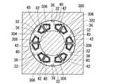
図6に、ステータコア30およびコイル42に充填されエンドカバー46を成形する絶縁樹脂材の成形型300を示す。成形型300は、外型302と内型304とを有している。この外型302と内型304との間に、ボビン40の周囲にコイル42を巻回したステータコア30を設置する。内型304のステータコア30と向き合う側には、周方向に隣接するティース32とティース32との隙間に内周側から嵌合し、ティース32の周方向位置を決める突起306が形成されている。ステータコア30のポンプ部12側の外周側端面35は、ボビン40の外周側で成形型300の底部に当接している。倒れ防止部材120はボビン40の端部に当接しており、倒れ防止部材120の嵌合穴にターミナル44が嵌合している。The
FIG. 6 shows a
このようにして、ステータコア30、ボビン40、コイル42、ターミナル44および倒れ防止部材120等のインサート部品を成形型300に設置した状態で、倒れ防止部材120側から成形型300内に絶縁樹脂材を充填し、エンドカバー46を射出成形する。このとき、ステータコア30のポンプ部12側の外周側端面35が成形型300の底部に当接しているので、成形型300に対するインサート部品の位置決めが容易であるとともに、ステータコア30に倒れ防止部材120側から軸方向に成形圧が加わっても、成形型300に対してステータコア30の軸方向位置がずれることを防止できる。 In this manner, the insulating resin material is inserted into the
また、成形型300に充填される絶縁樹脂材は各ティース32の外周面に形成された溝36にも充填されるので、各ティース32は成形圧により内型304に向けて押し付けられる。その結果、各ティース32の回転子80側の内周面は、内型304の外周面に沿って円周上に整列する。したがって、エンドカバー46を成形後に、ステータコア30と永久磁石84との間に形成されるギャップを、回転方向に均一にすることができる。 Further, since the insulating resin material filled in the
また、エンドカバー46の成型後に溝36に充填された絶縁樹脂材、あるいは各ティース32の間に充填された絶縁樹脂材がステータコア30の外周側でばりとなって脱落しても、脱落した樹脂ばりはステータコア30の外周側に形成される空間208に保持される。したがって、樹脂ばりが燃料ポンプ110の摺動部に噛み込み、燃料ポンプ110の昇圧を妨げることを防止できる。
また、倒れ防止部材120の嵌合穴にターミナル44が嵌合した状態で射出成形するので、樹脂成形圧によりターミナル44が倒れ、周囲部品と干渉することを防止できる。Further, even if the insulating resin material filled in the
Further, since the injection molding is performed with the terminal 44 fitted in the fitting hole of the
以上説明した第1実施形態〜第4実施形態では、金属ハウジングの内周面が形成している凹部内にステータコア30を収容しているので、ステータコア30の外周を覆うハウジングを薄肉化し、ブラシレスモータの外径を小径化できる。その結果、モータ効率の高いブラシレスモータを用いて小型化した燃料ポンプをさらに小型化できるので、特に自動二輪車のように燃料タンクが小さい場合にも、燃料タンク内に燃料ポンプを搭載できる。また、自動二輪車において燃料タンクが鞍型の場合にも、燃料タンク内の限られたスペースに燃料ポンプを搭載できる。 In the first to fourth embodiments described above, since the
(第5実施形態)
本発明の第5実施形態を図7に示す。尚、既述の実施形態と実質的に同一構成部分に同一符号を付す。
第5実施形態の燃料ポンプ130では、ハウジング132は、金属薄板をプレス加工することにより円筒状に形成されている。ハウジング132は、ポンプ部12の部品を収容する収容部134よりも内周側に凹ませた収容部135内に、ステータコア30を含むモータ部13の部品を収容している。つまり、収容部135の外径は収容部134の外径よりも小径であり、収容部134と収容部135との間には径差により段差136が形成されている。(Fifth embodiment)
A fifth embodiment of the present invention is shown in FIG. In addition, the same code | symbol is attached | subjected to substantially the same component as embodiment mentioned above.
In the
ハウジング132のポンプ部12と反対側の端部138はエンドカバー46の外周面140に圧入されている。さらに、端部138が外周面140に形成された段部142に軸方向に突き当てられていることにより、エンドカバー46およびステータコア30とハウジング132との軸方向の位置決めが成されている。
ポンプケース22は、ハウジング132の収容部134内に圧入され、ハウジング132の段差136に軸方向に突き当てられている。An
The
第5実施形態では、ポンプ部12の部品を収容する収容部134よりも内周側に凹ませてモータ部13の部品を収容する収容部135を形成しているので、ハウジング132を厚肉化することなくステータコア30を収容する収容部135を容易に形成し、モータ部13の外径が小径化されている。このように、モータ部13の外径が小径化されているので、自動二輪車のように燃料タンクが小さい場合にも、燃料タンク内に燃料ポンプを搭載できる。
また、ハウジング132の外周面には、収容部134と収容部135との径差による段差136が形成されているだけなので、ハウジング132の外周面に腐食防止のためのめっき処理を容易に、かつ均一に施すことができる。In the fifth embodiment, the
Further, since the outer surface of the
(他の実施形態)
上記複数の実施形態では、インペラ24を用いたタービンポンプでポンプ部12を構成したが、ポンプ部を他のポンプ構成、例えばギアポンプで構成してもよい。
また上記複数の実施形態では、ハウジング14、72、外周ハウジング94、内周ハウジング96、ハウジング132を金属で形成したが、これらハウジングを金属以外に、例えば樹脂で形成してもよい。(Other embodiments)
In the above embodiments, the
In the above embodiments, the
上記第4実施形態では、ステータコア30のポンプ部12側の軸方向端面34において、外周側端面35の全周が絶縁樹脂材から露出している。これに対し、外周側端面35の一部を成形型に当接させて絶縁樹脂材を充填し、外周側端面35の周方向の一部が絶縁樹脂材から露出している構成となってもよい。
このように、本発明は、上記複数の実施形態に限定されるものではなく、その要旨を逸脱しない範囲で種々の実施形態に適用可能である。In the fourth embodiment, the entire periphery of the outer peripheral
As described above, the present invention is not limited to the above-described plurality of embodiments, and can be applied to various embodiments without departing from the gist thereof.
10、70、90、110、130:燃料ポンプ、12:ポンプ部、13:モータ部(ブラシレスモータ)、14、72、92、132:ハウジング、14a、72a、92a:内周面、16:突部、19、76、99:凹部、20、22:ポンプケース、30:ステータコア、32:ティース、34:軸方向端面、35:外周側端面、36:溝、42:コイル、44:ターミナル、46:エンドカバー(カバー部材、絶縁樹脂材)、50、80、100:回転子、56、84:永久磁石、74:厚肉部(突部)、76a:軸方向端部、94:外周ハウジング、96:内周ハウジング(突部)、114:外周面、135:収容部、208:空間、300:成形型10, 70, 90, 110, 130: Fuel pump, 12: Pump part, 13: Motor part (brushless motor), 14, 72, 92, 132: Housing, 14a, 72a, 92a: Inner peripheral surface, 16: Projection Part, 19, 76, 99: recess, 20, 22: pump case, 30: stator core, 32: teeth, 34: axial end face, 35: outer peripheral end face, 36: groove, 42: coil, 44: terminal, 46 : End cover (cover member, insulating resin material), 50, 80, 100: Rotor, 56, 84: Permanent magnet, 74: Thick part (projection), 76a: End in axial direction, 94: Outer housing, 96: Inner peripheral housing (projection), 114: Outer peripheral surface, 135: Storage part, 208: Space, 300: Mold
Claims (3)
Translated fromJapanese前記ステータコアに巻回され、通電を制御されることにより前記ステータコアの内周面に周方向に形成する磁極を切り換えるコイルと、
前記ステータコアの内周側に回転自在に設置され、回転方向に交互に異なる磁極を前記ステータコアと向き合う外周面に形成している回転子と、
前記回転子により回転駆動される回転部材を有し、前記回転部材の回転により燃料を吸入し昇圧するポンプ部と、
内周面が形成する凹部内に前記ステータコアを収容するハウジングと、
前記コイルと電気的に接続し一部が外部に露出しているターミナルと、
前記ステータコア、前記コイルおよび前記ターミナルをインサート成形している絶縁樹脂材と、
を備え、
前記ステータコアの一方の軸方向端面の外周側端面の全周が前記絶縁樹脂材から露出しており、前記外周側端面は前記凹部の軸方向端部に突き当てられており、
前記絶縁樹脂材から露出している前記外周側端面は、前記ステータコアの前記ポンプ部側に形成され、前記絶縁樹脂材は前記ステータコアの前記ポンプ部と軸方向反対側を覆うカバー部材を形成し、前記カバー部材の外周面は前記ハウジングの前記内周面と接触して燃料シールを形成し、
前記ステータコアの外周面と、前記ハウジングの前記内周面と、前記カバー部材の前記外周面と前記ハウジングの前記内周面との接触箇所と、前記凹部の前記軸方向端部への前記外周側端面の突き当て箇所と、により空間が形成されている燃料ポンプ。A stator core;
A coil that is wound around the stator core and switches magnetic poles formed in the circumferential direction on the inner peripheral surface of the stator core by controlling energization;
A rotor that is rotatably installed on the inner peripheral side of the stator core and has magnetic poles that are alternately different in the rotation direction formed on the outer peripheral surface facing the stator core;
A pump unit that has a rotating member that is driven to rotate by the rotor, and that sucks and pressurizes fuel by rotation of the rotating member;
A housing that houses the stator core in a recess formed by an inner peripheral surface;
A terminal electrically connected to the coil and partially exposed to the outside;
An insulating resin material that insert-molds the stator core, the coil, and the terminal;
With
The entire circumference of the outer peripheral side end surface of one axial end surface of the stator core is exposed from the insulating resin material, and the outer peripheral side end surface is abutted against the axial end of the recess,
The outer peripheral side end surface exposed from the insulating resin material is formed on the pump portion side of the stator core, and the insulating resin material forms a cover member that covers an axially opposite side of the pump portion of the stator core, An outer peripheral surface of the cover member is in contact with the inner peripheral surface of the housing to form a fuel seal;
The outer peripheral surface of the stator core, the inner peripheral surface of the housing, the contact point between the outer peripheral surface of the cover member and the inner peripheral surface of the housing, and the outer peripheral side to the axial end of the recess A fuel pumpin which a space is formed by the abutting portion of the end face .
Priority Applications (9)
| Application Number | Priority Date | Filing Date | Title |
|---|---|---|---|
| JP2006171173AJP4893991B2 (en) | 2005-09-06 | 2006-06-21 | Fuel pump |
| DE102006000447ADE102006000447A1 (en) | 2005-09-06 | 2006-09-05 | Fluid pump with bearing hole |
| CN2008101689976ACN101368534B (en) | 2005-09-06 | 2006-09-05 | Fluid pump, electric motor, and manufature method thereof |
| DE102006000448ADE102006000448B4 (en) | 2005-09-06 | 2006-09-05 | Liquid pump with a housing |
| CNB2006101290505ACN100425822C (en) | 2005-09-06 | 2006-09-05 | Fluid pump having bearing hole |
| DE102006000446ADE102006000446B4 (en) | 2005-09-06 | 2006-09-05 | Fluid pump and electric motor and their manufacturing process |
| US11/515,790US20070052310A1 (en) | 2005-09-06 | 2006-09-06 | Fluid pump and electric motor, and manufacturing method for the same |
| US11/515,778US7950907B2 (en) | 2005-09-06 | 2006-09-06 | Fluid pump having housing |
| US11/515,807US20070065315A1 (en) | 2005-09-06 | 2006-09-06 | Fluid pump having bearing hold |
Applications Claiming Priority (3)
| Application Number | Priority Date | Filing Date | Title |
|---|---|---|---|
| JP2005257416 | 2005-09-06 | ||
| JP2005257416 | 2005-09-06 | ||
| JP2006171173AJP4893991B2 (en) | 2005-09-06 | 2006-06-21 | Fuel pump |
Publications (2)
| Publication Number | Publication Date |
|---|---|
| JP2007104890A JP2007104890A (en) | 2007-04-19 |
| JP4893991B2true JP4893991B2 (en) | 2012-03-07 |
Family
ID=37884353
Family Applications (1)
| Application Number | Title | Priority Date | Filing Date |
|---|---|---|---|
| JP2006171173AActiveJP4893991B2 (en) | 2005-09-06 | 2006-06-21 | Fuel pump |
Country Status (3)
| Country | Link |
|---|---|
| US (1) | US7950907B2 (en) |
| JP (1) | JP4893991B2 (en) |
| DE (1) | DE102006000448B4 (en) |
Families Citing this family (27)
| Publication number | Priority date | Publication date | Assignee | Title |
|---|---|---|---|---|
| JP4534677B2 (en)* | 2003-10-31 | 2010-09-01 | 株式会社デンソー | Fuel pump |
| DE102006000446B4 (en)* | 2005-09-06 | 2013-04-18 | Denso Corporation | Fluid pump and electric motor and their manufacturing process |
| DE102006000447A1 (en)* | 2005-09-06 | 2007-03-08 | Denso Corp., Kariya | Fluid pump with bearing hole |
| JP2007116767A (en)* | 2005-10-18 | 2007-05-10 | Denso Corp | Fuel pump |
| EP1918567A1 (en)* | 2006-10-27 | 2008-05-07 | Delphi Technologies, Inc. | Fuel delivery module |
| JP5042707B2 (en)* | 2007-05-17 | 2012-10-03 | アスモ株式会社 | Seal structure and rotating electric machine |
| JP4623217B2 (en)* | 2008-08-06 | 2011-02-02 | 株式会社デンソー | Fuel supply pump |
| JP5476040B2 (en)* | 2009-05-13 | 2014-04-23 | カヤバ工業株式会社 | motor |
| JP2010279178A (en)* | 2009-05-28 | 2010-12-09 | Sanyo Electric Co Ltd | Molded motor and electric vehicle |
| JP2011149393A (en)* | 2010-01-25 | 2011-08-04 | Sanden Corp | Fluid machine |
| JP5368524B2 (en)* | 2011-09-28 | 2013-12-18 | 三菱電機株式会社 | Resolver stator structure |
| US9246365B2 (en) | 2012-01-23 | 2016-01-26 | Aisan Kogyo Kabushiki Kaisha | Regulation of permanent magnet motion in a brushless motor |
| JP5962027B2 (en)* | 2012-01-26 | 2016-08-03 | 日本精工株式会社 | Rotating electric machine |
| JP5987331B2 (en)* | 2012-02-02 | 2016-09-07 | 株式会社ジェイテクト | Electric oil pump device |
| US9562534B2 (en) | 2012-05-04 | 2017-02-07 | Ghsp, Inc. | In-line dual pump and motor with control device |
| US9115720B2 (en)* | 2012-05-04 | 2015-08-25 | Ghsp, Inc. | Dual pump and motor with control device |
| US10087927B2 (en) | 2014-05-01 | 2018-10-02 | Ghsp, Inc. | Electric motor with flux collector |
| US11015585B2 (en) | 2014-05-01 | 2021-05-25 | Ghsp, Inc. | Submersible pump assembly |
| JP6232003B2 (en)* | 2015-02-18 | 2017-11-15 | ミネベアミツミ株式会社 | Terminal, terminal structure and rotating electric machine |
| DE102015010728A1 (en)* | 2015-08-17 | 2017-02-23 | Thomas Magnete Gmbh | A motor pump assembly |
| TWI654370B (en)* | 2016-06-15 | 2019-03-21 | 泓記精密股份有限公司 | Electric fuel pump |
| US10197023B2 (en)* | 2016-11-17 | 2019-02-05 | Ford Global Technologies, Llc | Saddle fuel tank |
| DE102019200499A1 (en)* | 2018-12-27 | 2020-07-02 | Robert Bosch Gmbh | Fuel pump |
| JP7264238B2 (en) | 2019-04-10 | 2023-04-25 | 株式会社Ihi | motor rotor |
| FR3106625B1 (en)* | 2020-01-27 | 2022-11-04 | Safran Helicopter Engines | Aircraft engine fuel system |
| EP4283842A4 (en)* | 2021-01-25 | 2025-01-01 | Hangzhou Ao Ke Mei Rui Technology Co., Ltd. | FLUID TRAINING DEVICE |
| US12215688B2 (en)* | 2023-03-30 | 2025-02-04 | Phinia Jersey Holdings Llc | Electronic positive displacement fluid pump and method of encapsulating the same |
Family Cites Families (30)
| Publication number | Priority date | Publication date | Assignee | Title |
|---|---|---|---|---|
| JPS57170647A (en)* | 1981-04-13 | 1982-10-20 | Toshiba Corp | Branch control system in data transmission system |
| JPS57176691U (en)* | 1981-04-30 | 1982-11-08 | ||
| DE3423316C2 (en)* | 1984-06-23 | 1993-10-21 | Bosch Gmbh Robert | Fuel delivery unit |
| JP2545819B2 (en) | 1987-01-14 | 1996-10-23 | 日本電装株式会社 | Brushless motor driven fuel pump |
| JPH0354365U (en)* | 1989-06-01 | 1991-05-27 | ||
| JPH0314966A (en)* | 1989-06-09 | 1991-01-23 | Komatsu Ltd | Variable displacement motor control device for hydraulically driven vehicles |
| US5356272A (en)* | 1990-09-05 | 1994-10-18 | Nippondenso Co., Ltd. | Fuel supply device and method of assembling same |
| US5120201A (en)* | 1990-12-17 | 1992-06-09 | Walbro Corporation | Brushless DC fuel pump responsive to pressure sensor |
| JP3402330B2 (en) | 1992-06-12 | 2003-05-06 | 株式会社デンソー | Fuel supply device |
| JP2988163B2 (en)* | 1992-10-30 | 1999-12-06 | 富士電機株式会社 | Water conditioning operation control device |
| DE4243225A1 (en) | 1992-12-19 | 1994-06-23 | Pierburg Gmbh | Fuel pump |
| DE4309382A1 (en)* | 1993-03-23 | 1994-09-29 | Bosch Gmbh Robert | Electronically commutated electric motor |
| JPH07231588A (en)* | 1994-02-18 | 1995-08-29 | Mitsubishi Electric Corp | Molded motor stator and manufacturing method thereof |
| DE19704403B4 (en)* | 1997-02-06 | 2006-10-05 | Ti Automotive (Neuss) Gmbh | fuel pump |
| SE9804525D0 (en)* | 1998-12-23 | 1998-12-23 | Itt Mfg Enterprises Inc | Locking |
| JP2000324769A (en)* | 1999-05-13 | 2000-11-24 | Matsushita Electric Ind Co Ltd | Stepping motor |
| JP2001268874A (en) | 2000-03-23 | 2001-09-28 | Nidec Shibaura Corp | Motor |
| JP3986838B2 (en)* | 2002-01-31 | 2007-10-03 | ミネベア株式会社 | Rotating electric machine |
| JP3814217B2 (en)* | 2002-04-03 | 2006-08-23 | 矢崎総業株式会社 | Mold for rotor |
| JP2004176704A (en)* | 2002-10-01 | 2004-06-24 | Ebara Corp | Gear pump |
| JP2004159395A (en)* | 2002-11-05 | 2004-06-03 | Tamagawa Seiki Co Ltd | Motor case and motor stator structure |
| US20050118044A1 (en)* | 2003-02-14 | 2005-06-02 | Seizo Inoue | Dc motor type fuel pump |
| US6765319B1 (en)* | 2003-04-11 | 2004-07-20 | Visteon Global Technologies, Inc. | Plastic molded magnet for a rotor |
| US20040208763A1 (en)* | 2003-04-21 | 2004-10-21 | Visteon Global Technologies, Inc. | Regenerative ring impeller pump |
| JP2005110478A (en)* | 2003-10-02 | 2005-04-21 | Aisan Ind Co Ltd | Motor and pump |
| JP2005110477A (en) | 2003-10-02 | 2005-04-21 | Aisan Ind Co Ltd | Motor and pump |
| DE102005015014A1 (en)* | 2004-04-02 | 2005-11-03 | Denso Corp., Kariya | Fuel pump, fuel supply device using the fuel pump and method of manufacturing the fuel pump |
| DE102006000447A1 (en)* | 2005-09-06 | 2007-03-08 | Denso Corp., Kariya | Fluid pump with bearing hole |
| DE102006000446B4 (en) | 2005-09-06 | 2013-04-18 | Denso Corporation | Fluid pump and electric motor and their manufacturing process |
| JP2007116767A (en)* | 2005-10-18 | 2007-05-10 | Denso Corp | Fuel pump |
- 2006
- 2006-06-21JPJP2006171173Apatent/JP4893991B2/enactiveActive
- 2006-09-05DEDE102006000448Apatent/DE102006000448B4/enactiveActive
- 2006-09-06USUS11/515,778patent/US7950907B2/enactiveActive
Also Published As
| Publication number | Publication date |
|---|---|
| DE102006000448A1 (en) | 2007-04-12 |
| US20070065314A1 (en) | 2007-03-22 |
| JP2007104890A (en) | 2007-04-19 |
| US7950907B2 (en) | 2011-05-31 |
| DE102006000448B4 (en) | 2013-05-08 |
Similar Documents
| Publication | Publication Date | Title |
|---|---|---|
| JP4893991B2 (en) | Fuel pump | |
| US7560839B2 (en) | Electric motor and fuel pump having the same | |
| US20070086905A1 (en) | Brushless motor and fluid pump having the same | |
| JP4797822B2 (en) | Manufacturing method of fuel pump | |
| JP2005273648A (en) | Electric pump | |
| US9954415B2 (en) | Rotor for brushless motor | |
| EP1783878B1 (en) | Fuel pump having motor arrangement and pump arrangement | |
| CN100552209C (en) | Fluid pump with housing | |
| US20070065315A1 (en) | Fluid pump having bearing hold | |
| JP4771137B2 (en) | MOTOR MANUFACTURING METHOD AND FUEL PUMP USING THE MOTOR | |
| JP2009222055A (en) | Fuel pump | |
| JP5696606B2 (en) | Brushless motor and fuel pump equipped with the same | |
| JP4587124B2 (en) | Fuel pump | |
| JP2007187145A (en) | Fuel pump | |
| JP4305853B2 (en) | Fuel supply device | |
| JP6562702B2 (en) | Pump and pump manufacturing method | |
| JP2008199740A (en) | Fuel pump and manufacturing method thereof | |
| JP2007159191A (en) | Motor | |
| JP6689127B2 (en) | Fuel pump | |
| JP4711232B2 (en) | Fuel pump and manufacturing method thereof | |
| JP5142463B2 (en) | Fuel pump | |
| JP5204718B2 (en) | Fuel pump | |
| CN113396530A (en) | Motor unit and liquid supply device | |
| JP6579986B2 (en) | Fuel pump | |
| JP2007037277A (en) | Electromagnetic actuator |
Legal Events
| Date | Code | Title | Description |
|---|---|---|---|
| A621 | Written request for application examination | Free format text:JAPANESE INTERMEDIATE CODE: A621 Effective date:20080723 | |
| A977 | Report on retrieval | Free format text:JAPANESE INTERMEDIATE CODE: A971007 Effective date:20110218 | |
| A131 | Notification of reasons for refusal | Free format text:JAPANESE INTERMEDIATE CODE: A131 Effective date:20110224 | |
| A521 | Request for written amendment filed | Free format text:JAPANESE INTERMEDIATE CODE: A523 Effective date:20110408 | |
| A131 | Notification of reasons for refusal | Free format text:JAPANESE INTERMEDIATE CODE: A131 Effective date:20110610 | |
| A521 | Request for written amendment filed | Free format text:JAPANESE INTERMEDIATE CODE: A523 Effective date:20110726 | |
| TRDD | Decision of grant or rejection written | ||
| A01 | Written decision to grant a patent or to grant a registration (utility model) | Free format text:JAPANESE INTERMEDIATE CODE: A01 Effective date:20111125 | |
| A01 | Written decision to grant a patent or to grant a registration (utility model) | Free format text:JAPANESE INTERMEDIATE CODE: A01 | |
| A61 | First payment of annual fees (during grant procedure) | Free format text:JAPANESE INTERMEDIATE CODE: A61 Effective date:20111208 | |
| R151 | Written notification of patent or utility model registration | Ref document number:4893991 Country of ref document:JP Free format text:JAPANESE INTERMEDIATE CODE: R151 | |
| FPAY | Renewal fee payment (event date is renewal date of database) | Free format text:PAYMENT UNTIL: 20150106 Year of fee payment:3 | |
| R250 | Receipt of annual fees | Free format text:JAPANESE INTERMEDIATE CODE: R250 | |
| R250 | Receipt of annual fees | Free format text:JAPANESE INTERMEDIATE CODE: R250 | |
| R250 | Receipt of annual fees | Free format text:JAPANESE INTERMEDIATE CODE: R250 | |
| R250 | Receipt of annual fees | Free format text:JAPANESE INTERMEDIATE CODE: R250 | |
| R250 | Receipt of annual fees | Free format text:JAPANESE INTERMEDIATE CODE: R250 | |
| R250 | Receipt of annual fees | Free format text:JAPANESE INTERMEDIATE CODE: R250 | |
| R250 | Receipt of annual fees | Free format text:JAPANESE INTERMEDIATE CODE: R250 | |
| R250 | Receipt of annual fees | Free format text:JAPANESE INTERMEDIATE CODE: R250 | |
| R250 | Receipt of annual fees | Free format text:JAPANESE INTERMEDIATE CODE: R250 | |
| S111 | Request for change of ownership or part of ownership | Free format text:JAPANESE INTERMEDIATE CODE: R313113 | |
| R350 | Written notification of registration of transfer | Free format text:JAPANESE INTERMEDIATE CODE: R350 | |
| R250 | Receipt of annual fees | Free format text:JAPANESE INTERMEDIATE CODE: R250 | |
| R250 | Receipt of annual fees | Free format text:JAPANESE INTERMEDIATE CODE: R250 |