JP4893693B2 - Vacuum heat press machine for multilayer circuit board formation - Google Patents
Vacuum heat press machine for multilayer circuit board formationDownload PDFInfo
- Publication number
- JP4893693B2 JP4893693B2JP2008141391AJP2008141391AJP4893693B2JP 4893693 B2JP4893693 B2JP 4893693B2JP 2008141391 AJP2008141391 AJP 2008141391AJP 2008141391 AJP2008141391 AJP 2008141391AJP 4893693 B2JP4893693 B2JP 4893693B2
- Authority
- JP
- Japan
- Prior art keywords
- pressure
- unit
- heating unit
- sheet material
- hot press
- Prior art date
- Legal status (The legal status is an assumption and is not a legal conclusion. Google has not performed a legal analysis and makes no representation as to the accuracy of the status listed.)
- Expired - Fee Related
Links
- 230000015572biosynthetic processEffects0.000title1
- 238000010438heat treatmentMethods0.000claimsdescription107
- 239000000463materialSubstances0.000claimsdescription87
- 238000001816coolingMethods0.000claimsdescription49
- 229920005989resinPolymers0.000claimsdescription46
- 239000011347resinSubstances0.000claimsdescription46
- 239000004020conductorSubstances0.000claimsdescription16
- 229920005992thermoplastic resinPolymers0.000claimsdescription12
- 238000005245sinteringMethods0.000claimsdescription10
- 230000004927fusionEffects0.000claimsdescription9
- 238000004519manufacturing processMethods0.000description33
- 238000000034methodMethods0.000description31
- 238000003825pressingMethods0.000description9
- 230000003028elevating effectEffects0.000description7
- 238000010586diagramMethods0.000description6
- 238000000465mouldingMethods0.000description5
- ATJFFYVFTNAWJD-UHFFFAOYSA-NTinChemical compound[Sn]ATJFFYVFTNAWJD-UHFFFAOYSA-N0.000description4
- 239000000498cooling waterSubstances0.000description4
- 239000010949copperSubstances0.000description4
- 238000001035dryingMethods0.000description4
- RYGMFSIKBFXOCR-UHFFFAOYSA-NCopperChemical compound[Cu]RYGMFSIKBFXOCR-UHFFFAOYSA-N0.000description3
- BQCADISMDOOEFD-UHFFFAOYSA-NSilverChemical compound[Ag]BQCADISMDOOEFD-UHFFFAOYSA-N0.000description3
- 238000007731hot pressingMethods0.000description3
- 239000011812mixed powderSubstances0.000description3
- 229910052709silverInorganic materials0.000description3
- 239000004332silverSubstances0.000description3
- RTAQQCXQSZGOHL-UHFFFAOYSA-NTitaniumChemical compound[Ti]RTAQQCXQSZGOHL-UHFFFAOYSA-N0.000description2
- 229910052802copperInorganic materials0.000description2
- 238000005530etchingMethods0.000description2
- 239000011888foilSubstances0.000description2
- 239000002184metalSubstances0.000description2
- 229910052751metalInorganic materials0.000description2
- 230000000630rising effectEffects0.000description2
- 238000004904shorteningMethods0.000description2
- 239000010936titaniumSubstances0.000description2
- 229910052719titaniumInorganic materials0.000description2
- 239000013256coordination polymerSubstances0.000description1
- 239000011889copper foilSubstances0.000description1
- 238000003795desorptionMethods0.000description1
- 238000011049fillingMethods0.000description1
- 239000011810insulating materialSubstances0.000description1
- 238000011068loading methodMethods0.000description1
- 238000002844meltingMethods0.000description1
- 230000008018meltingEffects0.000description1
- NJPPVKZQTLUDBO-UHFFFAOYSA-NnovaluronChemical compoundC1=C(Cl)C(OC(F)(F)C(OC(F)(F)F)F)=CC=C1NC(=O)NC(=O)C1=C(F)C=CC=C1FNJPPVKZQTLUDBO-UHFFFAOYSA-N0.000description1
- 230000003647oxidationEffects0.000description1
- 238000007254oxidation reactionMethods0.000description1
- 239000000088plastic resinSubstances0.000description1
- 238000004148unit processMethods0.000description1
Images


Landscapes
- Production Of Multi-Layered Print Wiring Board (AREA)
Description
Translated fromJapanese本発明は、多層回路基板形成用の真空熱プレス装置に関するものである。 The present invention relates to a vacuum hot press apparatus for forming a multilayer circuit board.
樹脂フィルム同士の貼り合わせと接続導体となる導電ペーストの焼結を一度の加熱加圧により一括して行う多層回路基板の製造方法が、例えば、特開2000−38464号公報(特許文献1)と特開2003−86948号公報(特許文献2)に開示されている。 For example, JP 2000-38464 A (Patent Document 1) discloses a method for manufacturing a multilayer circuit board in which bonding of resin films and sintering of a conductive paste serving as a connection conductor are performed at once by heat and pressure. It is disclosed by Unexamined-Japanese-Patent No. 2003-86948 (patent document 2).
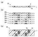
図6(a)〜(c)は、上記多層回路基板の製造方法の一例で、多層回路基板90の製造方法を示す模式的な工程別断面図である。 FIGS. 6A to 6C are schematic cross-sectional views by process showing the method for manufacturing the
図6に示す多層回路基板90の製造方法では、最初に、図6(a)に示すように、熱可塑性樹脂1からなる樹脂フィルムの片面に所定の導体パターン2aが形成され、導体パターン2aを底とする有底孔に導電ペースト4が充填された樹脂フィルム20を準備する。導体パターン2aは、樹脂フィルムの片面に例えば銅(Cu)箔を貼り合わせた後、該銅箔をエッチングして形成される。導電ペースト4には、例えば銀(Ag)と錫(Sn)の混合粉末からなる導電ペーストが用いられる。 In the manufacturing method of the
次に、上記工程で準備した樹脂フィルム20a〜20fを、図6(b)に示すように積層し、該積層体を熱プレス板により加熱加圧して、熱可塑性樹脂1からなる樹脂フィルム20a〜20fを相互に貼り合わせると共に、導電ペースト4を焼結させて接続導体4aとする。この積層体の熱プレス工程では、導体パターン2aの酸化を防止しつつ導電ペースト4を焼結させて樹脂フィルム20a〜20f同士を貼り合わせるため、高真空の環境下で、高温(320℃)、高圧(3.5Mpa)の真空熱プレスが実施される。これによって、図6(c)に示す多層回路基板90が製造される。 Next, the
多層回路基板の生産性を高めるため、上記積層体の熱プレス工程では、これまでバッチ型の大きな真空チャンバ内で、大型プレスによる多数個取りや多段化プレス等が検討されてきた。しかしながら、多数個取りでは大面積の熱プレス盤が必要で、該熱プレス盤の昇降温に多大な時間がかかり、ワークの投入から取り出しまで300分/バッチ以上の時間が必要とされる。また、熱プレス盤の加熱冷却エネルギー量も、ワーク処理に必要なエネルギー量に較べて膨大なものとなり、省エネルギーに反した装置となっている。 In order to increase the productivity of the multilayer circuit board, in the hot pressing process of the laminated body, a large number of large-size presses or multi-stage presses have been studied so far in a large batch type vacuum chamber. However, a large number of pieces requires a large-area hot press machine, and it takes a lot of time to raise and lower the temperature of the hot press machine, and a time of 300 minutes / batch or more is required from the loading of the workpiece to the removal. Further, the amount of heating and cooling energy of the hot press panel is enormous as compared with the amount of energy required for workpiece processing, which is a device contrary to energy saving.
一方、多段化プレスでは、次のような問題がある。上記多層回路基板の製造においては、導体パターンの変形や断線を防止するうえで、積層された各樹脂フィルムが互いに平行状態を保ったまま熱プレスされることが必要である。しかしながら、多段化プレスを行うと、積層された各樹脂フィルムの平行状態が崩れやすく、生産歩留まりが著しく低下してしまう。 On the other hand, the multistage press has the following problems. In the production of the multilayer circuit board, in order to prevent the conductor pattern from being deformed or disconnected, it is necessary that the laminated resin films be hot-pressed while maintaining a parallel state. However, when a multi-stage press is performed, the parallel state of the laminated resin films is easily broken, and the production yield is significantly reduced.
上記バッチ型の真空チャンバを用いた熱プレスの問題を改善する方法が、特許第3893930号明細書(特許文献3)に開示されている。 Japanese Patent No. 3893930 (Patent Document 3) discloses a method for improving the hot press problem using the batch type vacuum chamber.
図7は、特許文献3に開示された多層回路基板の製造方法を説明する図で、図7(a)は、シート材保持具40にシート材30を保持した状態を示す説明図であり、図7(b)は、加圧・加熱を行う装置100の概略構成を示した図である。 FIG. 7 is a diagram illustrating a method for manufacturing a multilayer circuit board disclosed in Patent Document 3, and FIG. 7A is an explanatory diagram illustrating a state in which the
図7(a)に示すシート材30は、図6(b)に示したような樹脂フィルム20a〜20fの積層体からなる。シート材30は、熱伝導性に優れる金属、例えばチタンを十分な剛性を有するように厚板状に形成した平坦なベース部41とカバー部42の間に挟まれて、シート材保持具40に入れられる。シート材30が入れられたシート材保持具40は、排気口11を介して、真空ポンプ15によって内部が減圧される。 The
図7(b)に示す装置100は、加熱及び加圧を行うプレス機120を備える。すなわち、プレス機120は、加圧するための一対の加圧ヘッド102,104を有する。これら、加圧ヘッド102,104の内部には、通電することにより発熱するヒータ103,105がそれぞれ内蔵されている。また、装置100には、加熱及び加圧を行うプレス機120に隣接して、冷却した加圧ヘッドによってシート材保持具40に保持されたシート材30を加圧するプレス機130が設けられている。プレス機130は、加圧を行う一対の加圧ヘッド107,109を有する。これら加圧ヘッド107,109の内部には冷却管108,110が配設されており、これら冷却管108,110に冷却水を流動させることにより、一対の加圧ヘッド107,109の温度を低温に保っている。 An
図7(b)に示す装置100では、内部にシート材30が入れられたシート材保持具40が台座に載せられると、上方加圧ヘッド102が下方加圧ヘッド104との間でシート材30を加圧できる位置まで下降され、ヒータ103,105によって加熱された一対の加圧ヘッド102,104が、シート材30を加熱しつつ加圧する。該加熱・加圧工程により、図6(b)で説明した樹脂フィルム20a〜20f同士の貼り合わせと導電ペースト4の焼結が行われる。 In the
プレス機120によって加熱・加圧工程が行われた後に、そのシート材30はシート材保持具40内に保持されたまま隣のプレス機130に移送され、冷却・加圧工程が行われる。すなわち、一対の加圧ヘッド107,109の温度を冷却水によって低温に保ちつつ、シート材保持具40内に保持されたシート材30を加圧する。この冷却・加圧工程は、加熱・加圧工程によって高温になったシート材30の温度を強制的に低下させるために行うものである。これにより、シート材30の温度低下に要する時間を短縮することができるので、生産リードタイムを短縮し、生産効率を向上することができる。冷却・加圧工程の終了後には、シート材保持具40内の密閉空間に大気が導入され、図6(c)に示す多層回路基板90のように製造が終了したシート材30がシート材保持具40より取り出される。
図7に示した多層回路基板の製造方法は、従来のバッチ型の真空チャンバを用いた熱プレスと異なり、樹脂フィルムの積層体からなるシート材30を一つずつシート材保持具40に保持した状態で加熱・加圧工程を行う、所謂、枚葉式の工程である。従って、図7(b)の装置100を用いた製造方法によれば、従来のバッチ型の真空チャンバを用いた工程に較べて、生産効率を大幅に向上することができると共に、加熱冷却のエネルギー利用効率も大幅に改善することができる。 The multilayer circuit board manufacturing method shown in FIG. 7 is different from the conventional press using a batch-type vacuum chamber in that the
一方、図7(b)の装置100を用いた製造方法では、シート材30の加熱温度や印加圧力の制御が、従来のバッチ型の真空チャンバを用いた熱プレスに較べて困難である。このため、図7(b)の装置100では、多層回路基板を高い歩留りや高精度で製造することが困難となっている。 On the other hand, in the manufacturing method using the
そこで本発明の目的は、多層回路基板を製造するための生産効率やエネルギー利用効率に優れる枚葉式の真空熱プレス装置であって、高精度な多層回路基板を高い歩留りで製造することのできる真空熱プレス装置を提供することにある。 Therefore, an object of the present invention is a single-wafer type vacuum heat press apparatus excellent in production efficiency and energy utilization efficiency for manufacturing a multilayer circuit board, and can manufacture a highly accurate multilayer circuit board with a high yield. The object is to provide a vacuum hot press apparatus.
請求項1に記載の発明は、多層回路基板を形成するための樹脂フィルムの積層体からなるシート材の真空熱プレス装置であって、前記シート材を密閉空間内に保持し、該密閉空間内を減圧した状態でシート材に熱および圧力を伝達可能なシート材保持具をワークとして、該ワークに対して外部から加圧加熱する第1加圧加熱ユニットと、前記第1加圧加熱ユニットにより処理された前記ワークに対して、外部から加圧加熱する第2加圧加熱ユニットと、前記第2加圧加熱ユニットにより処理された前記ワークに対して、外部から加圧冷却する加圧冷却ユニットとを有してなり、前記第1加圧加熱ユニット、第2加圧加熱ユニットおよび加圧冷却ユニットが、円周上に配置されてなり、前記ワークが、前記円周の中心に配置された旋回機構により、前記第1加圧加熱ユニット、第2加圧加熱ユニットおよび加圧冷却ユニットの各処理位置に搬送され、前記第1加圧加熱ユニット、第2加圧加熱ユニットおよび加圧冷却ユニットが、それぞれ、前記ワークを間に挟んで加圧加熱または加圧冷却する上側プレスユニットと下側プレスユニットとを有してなり、前記下側プレスユニットの下側加圧プレートが、昇降シリンダとスライドガイドからなる移動機構により昇降され、前記下側加圧プレートが、キーブロックからなるロックアップ機構により、所定の上昇位置で固定されることを特徴としている。 The invention according to
上記真空熱プレス装置は、樹脂フィルムの積層体からなるシート材が密閉空間内に減圧状態で保持されているシート材保持具をワークとして、該ワークを第1加圧加熱ユニット、第2加圧加熱ユニットおよび加圧冷却ユニットの各ユニットに一つずつ一定方向に順次搬送し、上記各ユニットでシート材をシート材保持具の外部から加圧加熱または加圧冷却していく、所謂、枚葉式の真空熱プレス装置である。従って、上記真空熱プレス装置は、大きな真空チャンバを用いたバッチ型の真空熱プレス装置に較べて、生産効率やエネルギー利用効率に優れている。 The vacuum hot press apparatus uses a sheet material holder in which a sheet material made of a laminate of resin films is held in a sealed space in a reduced pressure state, and the workpiece is used as a first pressure heating unit and a second pressure. A so-called single-wafer, which is sequentially conveyed to each unit of the heating unit and the pressure cooling unit one by one in a certain direction, and the sheet material is pressurized and heated or cooled from the outside of the sheet material holder by each unit. This is a vacuum heat press device of the type. Therefore, the vacuum hot press apparatus is superior in production efficiency and energy utilization efficiency as compared with a batch type vacuum hot press apparatus using a large vacuum chamber.
上記真空熱プレス装置において、第1加圧加熱ユニット、第2加圧加熱ユニットおよび加圧冷却ユニットの各ユニットは、円周上に配置されており、ワークを円周の中心に配置された旋回機構で間欠回転させて、各ユニットの処理位置に素早く搬送することができる。 In the above vacuum hot press apparatus, each of the first pressure heating unit, the second pressure heating unit, and the pressure cooling unit is arranged on the circumference, and the workpiece is arranged at the center of the circumference. It can be intermittently rotated by the mechanism and quickly transferred to the processing position of each unit.
また、上記真空熱プレス装置は、第1加圧加熱ユニットと第2加圧加熱ユニットの2つの加圧加熱ユニットを有しており、樹脂フィルムの積層体からなるシート材に対して、圧力および温度の異なる2段階の処理を実施することができる。また、ワークであるシート材保持具は、上記したように各ユニット間を素早く搬送される。 The vacuum hot press apparatus includes two pressure heating units, a first pressure heating unit and a second pressure heating unit, and applies pressure and pressure to a sheet material made of a laminate of resin films. Two-stage processing with different temperatures can be performed. Further, the sheet material holder as a workpiece is quickly conveyed between the units as described above.
さらに、上記真空熱プレス装置においては、前記下側プレスユニットの下側加圧プレートが、昇降シリンダとスライドガイドからなる移動機構により昇降される構成となっている。これにより、例えば後の上側プレスユニットの移動機構で示すボールねじによる移動機構を採用する場合に較べて、下側加圧プレートを高速で昇降することができる。このように、下側加圧プレートの昇降時間を短縮することで、ワークを各ユニット内の所定のプレス位置に素早く搬送することができ、各ユニット内工程でワークの温度維持や処理時間の短縮を図ることができる。 Furthermore, in the said vacuum hot press apparatus, the lower side pressurization plate of the said lower side press unit becomes a structure raised / lowered by the moving mechanism which consists of a raising / lowering cylinder and a slide guide. Thereby, for example, the lower pressure plate can be moved up and down at a higher speed than when a moving mechanism using a ball screw shown in the moving mechanism of the upper press unit later is employed. In this way, by shortening the raising and lowering time of the lower pressure plate, the workpiece can be quickly transported to a predetermined press position in each unit, and the temperature of the workpiece and the processing time can be reduced in each unit process. Can be achieved.
また、上記真空熱プレス装置において、前記下側加圧プレートは、キーブロックからなるロックアップ機構により、所定の上昇位置で固定される構成となっている。これにより、下側加圧プレートを上記昇降シリンダとスライドガイドからなる移動機構でプレス位置まで高速で上昇させた場合であっても、正確なプレス位置を確保することができる。 In the vacuum hot press apparatus, the lower pressure plate is configured to be fixed at a predetermined raised position by a lockup mechanism including a key block. Thereby, even when the lower pressure plate is raised to the press position at a high speed by the moving mechanism including the lifting cylinder and the slide guide, an accurate press position can be secured.
以上示したように、上記真空熱プレス装置では、搬送の間におけるワークの温度を確実に維持することができる。これによって、樹脂フィルムの積層体からなるシート材の熱処理温度を厳密に制御することができ、高精度な多層回路基板を高い歩留りで製造することができる。 As described above, the vacuum hot press apparatus can reliably maintain the temperature of the workpiece during conveyance. This makes it possible to strictly control the heat treatment temperature of the sheet material made of a laminate of resin films, and to manufacture a highly accurate multilayer circuit board with a high yield.
以上のようにして、上記真空熱プレス装置は、多層回路基板を製造するための生産効率やエネルギー利用効率に優れる枚葉式の真空熱プレス装置であって、高精度な多層回路基板を高い歩留りで製造することのできる真空熱プレス装置となっている。 As described above, the vacuum heat press apparatus is a single-wafer type vacuum heat press apparatus that is excellent in production efficiency and energy utilization efficiency for manufacturing a multilayer circuit board. It is a vacuum hot press device that can be manufactured by.
上記真空熱プレス装置は、請求項2に記載のように、前記旋回機構が、ロータリ真空バルブを有してなり、前記シート材保持具の密閉空間内が、前記ロータリ真空バルブを介して、前記第1加圧加熱ユニット、第2加圧加熱ユニットおよび加圧冷却ユニットによる処理中、並びに前記旋回機構による搬送中にも、減圧状態が維持される構成とすることが好ましい。 In the vacuum hot press apparatus, as described in claim 2, the swivel mechanism includes a rotary vacuum valve, and the sealed space of the sheet material holder is inserted into the sealed space through the rotary vacuum valve. It is preferable that the depressurized state is maintained even during processing by the first pressure heating unit, the second pressure heating unit, and the pressure cooling unit, and also during conveyance by the turning mechanism.
これによれば、シート材保持具の密閉空間内を当該真空熱プレス装置への投入前に予め真空引きするだけでなく、該密閉空間内を、上記ロータリ真空バルブを介して、各ユニットでの処理中および旋回機構による搬送中にも真空引きすることができる。従って、例えば加圧加熱処理中において該密閉空間内に保持されているシート材から発生するガスを排出できると共に、シート材に形成されている導体パターンや導電ペースト等の酸化を確実に防止することができる。 According to this, not only the inside of the sealed space of the sheet material holder is evacuated in advance before being put into the vacuum heat press apparatus, but also the inside of the sealed space is connected to each unit via the rotary vacuum valve. A vacuum can also be drawn during processing and during conveyance by the turning mechanism. Therefore, for example, gas generated from the sheet material held in the sealed space during the pressure heat treatment can be discharged, and oxidation of the conductor pattern or conductive paste formed on the sheet material can be reliably prevented. Can do.
また、上記真空熱プレス装置は、請求項3に記載のように、前記上側プレスユニットの上側加圧プレートが、少なくとも3対のボールねじからなる移動機構により昇降される構成とすることが好ましい。 Further, the vacuum hot press apparatus is preferably configured such that the upper pressure plate of the upper press unit is raised and lowered by a moving mechanism including at least three pairs of ball screws.
上側プレスユニットの上側加圧プレートの昇降機構として、少なくとも3対のボールねじからなる移動機構を採用することで、上側加圧プレートの傾きを該少なくとも3対のボールねじで精密に制御することができる。これによって、対となる下側プレスユニットの下側加圧プレートに対する平行度を、高い精度で確保することができる。従って、樹脂フィルムの積層体からなるシート材に均等な圧力をかけることができ、高精度な多層回路基板を高い歩留りで製造することができる。 By adopting a moving mechanism consisting of at least three pairs of ball screws as the lifting mechanism of the upper pressure plate of the upper press unit, the inclination of the upper pressure plate can be precisely controlled with the at least three pairs of ball screws. it can. Thereby, the parallelism with respect to the lower pressure plate of the lower press unit to be paired can be ensured with high accuracy. Therefore, a uniform pressure can be applied to the sheet material made of a laminate of resin films, and a highly accurate multilayer circuit board can be manufactured with a high yield.
また、上記真空熱プレス装置においては、請求項4に記載のように、ロードセルが、前記加圧加熱または加圧冷却時において、前記少なくとも3対のボールねじの下方にそれぞれ配置されることが好ましい。 Moreover, in the said vacuum hot press apparatus, as described in Claim 4, it is preferable that a load cell is each arrange | positioned under the said at least 3 pair of ball screw at the time of the said pressure heating or pressure cooling. .
これによって、上記した少なくとも3対のボールねじによる上側加圧プレートの傾きの制御を、それぞれの下方に配置されているロードセルの荷重をフィードバックさせて行うことができる。これによって、樹脂フィルムの積層体からなるシート材にかける圧力をより均等にすることができ、高精度な多層回路基板を高い歩留りで製造することができる。 Thereby, the control of the inclination of the upper pressure plate by the at least three pairs of ball screws can be performed by feeding back the load of the load cell disposed below each of the upper pressure plates. As a result, the pressure applied to the sheet material made of a laminate of resin films can be made more uniform, and a highly accurate multilayer circuit board can be manufactured with a high yield.
上記真空熱プレス装置においては、請求項5に記載のように、前記樹脂フィルムが、熱可塑性樹脂からなり、一方の表面に導体パターンが形成され、該導体パターンを底とする孔に導電ペーストが充填されてなる樹脂フィルムである場合に好適で、この場合には、前記第1加圧加熱ユニットの加熱温度を、前記導電ペーストの焼結温度に設定し、前記第2加圧加熱ユニットの加熱温度を、前記熱可塑性樹脂の融着温度に設定することが好ましい。 In the vacuum hot press apparatus, as described in claim 5, the resin film is made of a thermoplastic resin, a conductor pattern is formed on one surface, and a conductive paste is formed in a hole having the conductor pattern as a bottom. It is suitable for a resin film that is filled. In this case, the heating temperature of the first pressure heating unit is set to the sintering temperature of the conductive paste, and the heating of the second pressure heating unit is performed. It is preferable to set the temperature to the fusion temperature of the thermoplastic resin.
製造する多層回路基板が、熱可塑性樹脂からなる樹脂フィルムの一方の表面に形成された導体パターンを底とする孔に導電ペーストが充填され、該樹脂フィルムの積層体を真空熱プレスして製造するものである場合、真空熱プレス工程は、大別すると(1)導電ペーストの乾燥および焼結、(2)樹脂フィルム同士の融着、(3)冷却成形の3段階のプロファイルを制御できることが重要である。 A multilayer circuit board to be manufactured is manufactured by filling a hole with a conductive pattern at the bottom formed on one surface of a resin film made of a thermoplastic resin with a conductive paste, and vacuum-pressing the laminate of the resin film If it is, the vacuum hot press process can be broadly divided into three profiles: (1) drying and sintering of conductive paste, (2) fusion between resin films, and (3) cooling molding. It is.
従って、上記したように、第1加圧加熱ユニットの加熱温度を導電ペーストの焼結温度に設定し、第2加圧加熱ユニットの加熱温度を熱可塑性樹脂の融着温度に設定し、加圧冷却ユニットを冷却成形処理に用いることで、各処理に適した温度と圧力を設定することができ、高精度な多層回路基板を高い歩留りで製造することができる。 Therefore, as described above, the heating temperature of the first pressure heating unit is set to the sintering temperature of the conductive paste, the heating temperature of the second pressure heating unit is set to the fusion temperature of the thermoplastic resin, and pressurization is performed. By using the cooling unit for the cooling molding process, the temperature and pressure suitable for each process can be set, and a highly accurate multilayer circuit board can be manufactured with a high yield.
以上のようにして、上記した真空熱プレス装置は、多層回路基板を製造するための生産効率やエネルギー利用効率に優れる枚葉式の真空熱プレス装置であって、高精度な多層回路基板を高い歩留りで製造することのできる真空熱プレス装置とすることができる。 As described above, the vacuum heat press apparatus described above is a single wafer vacuum heat press apparatus that is excellent in production efficiency and energy utilization efficiency for manufacturing a multilayer circuit board, and has a high precision multilayer circuit board. It can be set as the vacuum hot press apparatus which can be manufactured with a yield.
本発明は、多層回路基板を形成するための真空熱プレス装置に係るもので、樹脂フィルムの積層体からなるシート材の真空熱プレス装置に関する。以下、本発明を実施するための最良の形態を、図に基づいて説明する。 The present invention relates to a vacuum hot press apparatus for forming a multilayer circuit board, and relates to a vacuum hot press apparatus for a sheet material made of a laminate of resin films. The best mode for carrying out the present invention will be described below with reference to the drawings.
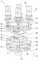
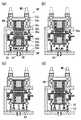
図1は、本発明の真空熱プレス装置の一例で、真空熱プレス装置200を模式的に示した斜視図である。図2は、図1の真空熱プレス装置200に投入されるワークを説明する図で、シート材30と開いた状態にあるシート材保持具40を模式的に示した斜視図である。図2に示したシート材30およびシート材保持具40は、図7(a)で説明したものと同様であり、同じ符号を付した。図3は、図1の真空熱プレス装置200の構成要素である第1加圧加熱ユニットHU1、第2加圧加熱ユニットHU2および加圧冷却ユニットCUの基本構造Uを模式的に示した斜視図である。また、図4(a)〜(d)は、ワーク40aが定位置にきた後の各ユニットHU1,HU2,CUでの一連の動作を説明する図で、それぞれ、部分断面図で動作途中の各状態を示している。 FIG. 1 is a perspective view schematically showing a vacuum
図1に示す真空熱プレス装置200は、図2に示すシート材30を内部に保持したシート材保持具40をワークとする真空熱プレス装置である。 A vacuum
図2のシート材30は、図6(b)に示したような樹脂フィルム20a〜20fの積層体からなり、個々の樹脂フィルム20a〜20fは、図6(a)に示したように、熱可塑性樹脂1からなる樹脂フィルムの片面に所定の導体パターン2aが形成され、導体パターン2aを底とする有底孔に導電ペースト4が充填されている。代表的には、導体パターン2aは、銅(Cu)箔をエッチングして形成され、導電ペースト4には、銀(Ag)と錫(Sn)の混合粉末からなる導電ペーストが用いられる。尚、以下の説明においては、図1,2に示したシート材30として、図6(a)〜(c)に示した樹脂フィルム20,20a〜20fとその各部の符号を参照する。 The
図2に示すように、シート材30は、熱伝導性に優れる金属(例えばチタン)を十分な剛性を有するように厚板状に形成した平坦なベース部41とカバー部42の間に挟まれて、シート材保持具40に入れられる。シート材30が入れられたシート材保持具40は、図7(a)に示したように、閉じた状態にして、排気口11を介して、真空ポンプにより内部が減圧される。 As shown in FIG. 2, the
以上のように、図1の真空熱プレス装置200は、シート材30を密閉空間内に保持し、該密閉空間内を減圧した状態でシート材30に熱および圧力を伝達可能なシート材保持具40をワーク40aとしている。 As described above, the vacuum
図1に示す真空熱プレス装置200は、上記ワーク40aに対して外部から加圧加熱する第1加圧加熱ユニットHU1と、第1加圧加熱ユニットHU1により処理されたワーク40aに対して外部から加圧加熱する第2加圧加熱ユニットHU2と、第2加圧加熱ユニットHU2により処理されたワーク40aに対して外部から加圧冷却する加圧冷却ユニットCUとを有している。第1加圧加熱ユニットHU1、第2加圧加熱ユニットHU2および加圧冷却ユニットCUは、円周上に配置されている。ワーク40aは、円周の中心に配置された旋回機構RMにより、旋回プレートRPに載せられて、軌道レールRL上を間歇回転して移動し、第1加圧加熱ユニットHU1、第2加圧加熱ユニットHU2および加圧冷却ユニットCUの各処理位置に搬送される。 A vacuum
図1に示す真空熱プレス装置200は、樹脂フィルム20a〜20fの積層体からなるシート材30が密閉空間内に減圧状態で保持されているシート材保持具40をワーク40aとして、該ワーク40aを第1加圧加熱ユニットHU1、第2加圧加熱ユニットHU2および加圧冷却ユニットCUの各ユニットに一つずつ一定方向に順次搬送し、上記各ユニットHU1,HU2,CUでシート材30をシート材保持具40の外部から加圧加熱または加圧冷却していく、所謂、枚葉式の真空熱プレス装置である。従って、図1の真空熱プレス装置200は、大きな真空チャンバを用いたバッチ型の真空熱プレス装置に較べて、生産効率やエネルギー利用効率に優れている。 A vacuum
図1の真空熱プレス装置200は、図6(a)に示したように熱可塑性樹脂からなる樹脂フィルム20の導体パターン2aを底とする孔に導電ペースト4が充填され、図6(b)に示した樹脂フィルム20a〜20fの積層体を一括して真空熱プレスして、図6(c)の多層回路基板90を製造するのに好適な装置となっている。真空熱プレス装置200は、第1加圧加熱ユニットHU1と第2加圧加熱ユニットHU2の2つの加圧加熱ユニットを有しており、樹脂フィルム20a〜20fの積層体からなるシート材30に対して、次に示すように、圧力および温度の異なる2段階の処理を実施することができる。 As shown in FIG. 6A, the vacuum
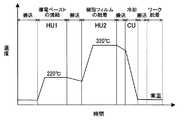
図5は、図1の真空熱プレス装置200を用いて行う真空熱プレス工程の一例を模式的に示した図である。 FIG. 5 is a view schematically showing an example of a vacuum hot press process performed using the vacuum
上記したように導体パターン2aを底とする孔に導電ペースト4が充填された熱可塑性樹脂からなる樹脂フィルム20a〜20fの積層体を真空熱プレスして多層回路基板90を製造する場合、真空熱プレス工程は、大別すると(1)導電ペースト4の乾燥および焼結、(2)樹脂フィルム20a〜20f同士の融着、(3)冷却成形の3段階のプロファイルを制御できることが重要である。尚、前述した銀(Ag)と錫(Sn)の混合粉末からなる導電ペースト4を用いる場合には、(2)の樹脂フィルム20a〜20f同士の融着段階において、錫の拡散が同時になされる。 When the
上記3段階のプロファイルを制御するため、図1の真空熱プレス装置200では、図5に示すように、第1加圧加熱ユニットHU1の加熱温度を導電ペースト4の焼結温度220℃に設定し、第2加圧加熱ユニットHU2の加熱温度を熱可塑性樹脂からなる樹脂フィルム20a〜20fの融着温度320℃に設定し、加圧冷却ユニットCUを冷却成形処理に用いている。このように、図1の真空熱プレス装置200は、第1加圧加熱ユニットHU1と第2加圧加熱ユニットHU2について、それぞれ導電ペースト4の焼結と樹脂フィルム20a〜20fの融着の各処理に適した温度と圧力を設定することができる。 In order to control the above three-stage profile, the vacuum
また、図1の真空熱プレス装置200では、第1加圧加熱ユニットHU1、第2加圧加熱ユニットHU2および加圧冷却ユニットCUの各ユニットが、円周上に配置されている。特に、真空熱プレス装置200では、ワーク40aの脱着位置を含めて、各ユニットHU1,HU2,CUが、円周の中心に配置された旋回機構RMに対して、十字型に配置されている。該真空熱プレス装置200では、ワーク40aが円周の中心に配置された旋回機構RMを用いて間欠回転され、各ユニットHU1,HU2,CUの処理位置に素早く搬送される。従って、真空熱プレス装置200では、搬送の間におけるワーク40aの冷却を抑制することができ、ワーク40aの温度を確実に維持することができる。これによって、樹脂フィルム20a〜20fの積層体からなるシート材30の熱処理温度を厳密に制御することができ、高精度な多層回路基板90を高い歩留りで製造することができる。 Moreover, in the vacuum
以上のようにして、図1に示した真空熱プレス装置200は、多層回路基板を製造するための生産効率やエネルギー利用効率に優れる枚葉式の真空熱プレス装置であって、高精度な多層回路基板90を高い歩留りで製造することのできる真空熱プレス装置となっている。 As described above, the vacuum
次に、上記した真空熱プレス装置200の細部について、より詳細に説明する。 Next, details of the above-described vacuum
図1に示す真空熱プレス装置200は、ワーク40aの旋回機構RMが、ロータリ真空バルブ(図示省略)を有しており、シート材保持具40の密閉空間内が、該ロータリ真空バルブを介して、第1加圧加熱ユニットHU1、第2加圧加熱ユニットHU2および加圧冷却ユニットCUによる処理中、並びに旋回機構RMによる搬送中にも、減圧状態が維持される構造となっている。 In the vacuum
これによれば、シート材保持具40の密閉空間内を当該真空熱プレス装置200への投入前に予め真空引きするだけでなく、該密閉空間内を、上記ロータリ真空バルブを介して、各ユニットHU1,HU2,CUでの処理中および旋回機構RMによる搬送中にも真空引きすることができる。従って、例えば加圧加熱処理中において該密閉空間内に保持されているシート材30(導電ペースト4)から発生するガスを排出できると共に、シート材30に形成されている導体パターン2aや導電ペースト4等の酸化を確実に防止することができる。 According to this, not only the inside of the sealed space of the
図3の基本構造Uに示すように、真空熱プレス装置200の第1加圧加熱ユニットHU1、第2加圧加熱ユニットHU2および加圧冷却ユニットCUは、それぞれ、ワーク40aを間に挟んで加圧加熱または加圧冷却する上側プレスユニットUPと下側プレスユニットDPとを有している。 As shown in the basic structure U of FIG. 3, the first pressurizing / heating unit HU1, the second pressurizing / heating unit HU2, and the pressurizing / cooling unit CU of the vacuum
図1の真空熱プレス装置200における第1加圧加熱ユニットHU1と第2加圧加熱ユニットHU2は、それぞれ、前述した(1)の導電ペースト4の乾燥および焼結段階と(2)の樹脂フィルム20a〜20f同士の融着段階を実施する部分である。従って、第1加圧加熱ユニットHU1と第2加圧加熱ユニットHU2では、図3の基本構造Uにおける上側加圧プレート50uと下側加圧プレート50dに、加熱ヒータHが設けてあり、上側加圧プレート50uと下側加圧プレート50dが熱盤となっている。一方、図1の真空熱プレス装置200における加圧冷却ユニットCUは、前述した(3)の冷却成形段階を実施する部分である。従って、加圧冷却ユニットCUでは、図3の基本構造Uにおける上側加圧プレート50uと下側加圧プレート50dに、冷却水Cが導入される構造となっている。また、上記加圧プレート50u,50dの周りには断熱壁DWが設けられており、断熱壁DWの構成も各ユニットHU1,HU2,CUで異なる。しかしながら、図1の真空熱プレス装置200において、加圧プレート50u,50dと断熱壁DW以外の主な構成、例えば加圧プレート50u,50dの昇降機構の構成は、各ユニットHU1,HU2,CU共に、図3と図4に示した共通の構成となっている。 The first pressurizing and heating unit HU1 and the second pressurizing and heating unit HU2 in the vacuum
図3に示す上側プレスユニットUPは、駆動モータMOの乗った駆動プレート53u、上側加圧プレート50uを吊り下げた上側昇降プレート54u、およびボールねじBNを4隅に配置した上面プレート55uの3層構造となっており、上面プレート55uが設備の構造体に固定されている。上側昇降プレート54uは、4隅にボールねじBNのナット部、中央に加熱加圧用のヒータブロックまたは冷却加圧用の冷却ブロックが取り付けてあり、該ブロックの先端面が平面度の高い上側加圧プレート50uとなっている。尚、第1加圧加熱ユニットHU1と第2加圧加熱ユニットHU2においては、上側昇降プレート54uとヒータブロック間に冷却水の通る回路が設けられた断熱材からなる断熱冷却プレートCPが挿入されており、ヒータブロックからの熱伝導によってボールねじBNのナット部が損傷しないようになっている。 The upper press unit UP shown in FIG. 3 includes three layers: a
図3の基本構造Uでは、駆動プレート53uの4隅に各ボールねじBNの駆動モータMOが取り付けてあり、必要に応じ個別または連携してボールねじBNを回転し、上側昇降プレート54u(従って上側加圧プレート50u)を昇降する構成となっている。このように、上側プレスユニットUPの上側加圧プレート50uは、少なくとも3対のボールねじBNからなる移動機構により昇降される構成とすることが好ましい。これによれば、上側加圧プレート50uの傾きを該少なくとも3対のボールねじで精密に制御することができ、対となる下側プレスユニットDPの下側加圧プレート50dに対する平行度を高い精度で確保することができる。従って、樹脂フィルム20a〜20fの積層体からなるシート材30に均等な圧力をかけることができ、高精度な多層回路基板90を高い歩留りで製造することができる。 In the basic structure U of FIG. 3, the drive motors MO of the respective ball screws BN are attached to the four corners of the
次に、下側プレスユニットDPの構成を説明する。図3に示すように、下側プレスユニットDPは、基本的には上側プレスユニットUPを上下反転した構造となっているが、下側プレスユニットDPの下側昇降プレート54dの4隅には、スライドガイドSGが設けてある。そして、下側昇降プレート54dは、下面プレート55dと昇降シリンダCYを取り付けた駆動プレート53dの間で支持されている。下側プレスユニットDPは、駆動プレート53dで設備の構造体に固定されており、上下ユニットの位置関係を保っている。また、駆動プレート53dにはロックアップ機構LUが搭載されており、ロードセル(図示省略)を乗せた可動式のキーブロックKBが作動することにより、下側プレスユニットDPの下側昇降プレート54d(従って下側加圧プレート50d)を上昇位置に保持する構造となっている。 Next, the configuration of the lower press unit DP will be described. As shown in FIG. 3, the lower press unit DP basically has a structure in which the upper press unit UP is turned upside down, but at the four corners of the
以上のように、下側プレスユニットDPの下側加圧プレート50dは、昇降シリンダCYとスライドガイドSGからなる移動機構により昇降されることが好ましい。これによれば、例えば上側プレスユニットUPと同じボールねじによる移動機構を採用する場合に較べて、下側加圧プレート50dを高速で昇降することができる。このように、下側加圧プレート50dの昇降時間を短縮することで、ワーク40aを各ユニットHU1,HU2,CU内の所定のプレス位置に素早く搬送することができ、各ユニットHU1,HU2,CU内工程でワーク40aの温度維持や処理時間の短縮を図ることができる。 As described above, the
また、この場合、下側加圧プレート50dは、上記したようにキーブロックKBからなるロックアップ機構LUにより、所定の上昇位置で固定される構成とすることが好ましい。これによれば、下側加圧プレート50dを昇降シリンダCYとスライドガイドSGからなる移動機構でプレス位置まで高速で上昇させた場合であっても、正確なプレス位置を確保することができる。 In this case, it is preferable that the
次に、真空熱プレス装置200のより具体的な動作例について説明する。 Next, a more specific operation example of the vacuum
図1の真空熱プレス装置200において、第1加圧加熱ユニットHU1は、前述した(1)の導電ペースト4の乾燥および焼結段階を担うため、上側加圧プレート50uと下側加圧プレート50dが230℃に昇温保持されている。第2加圧加熱ユニットHU2は、前述した(2)の樹脂フィルム20a〜20f同士の融着段階を担うため、上側加圧プレート50uと下側加圧プレート50dが330℃に昇温保持されている。加圧冷却ユニットCUは、前述した(3)の冷却成形段階を担うため、上側加圧プレート50uと下側加圧プレート50dが20℃に冷却保持されている。また、各ユニットHU1,HU2,CUの後述するプレス圧力は、3.5Mpa(荷重10Ton)を目標値として制御されるように設定した。 In the vacuum
ワーク40aは、図1の各ユニットHU1,HU2,CU内において、図3の上側プレスユニットUPが上昇端、下側プレスユニットDPがロックアップ機構LUを解除して下降端にある時、旋回機構RMで回転させることができる。図3の上側加圧プレート50uと下側加圧プレート50dは中心が同じ軸上にあり、ワーク40aは、その中心が前記中心軸に一致するように、図1の十字型に配置された各ユニットHU1,HU2,CUに旋回機構RMで搬送される。以上のようにして、搬送が終了した時点では、図1の真空熱プレス装置200における各ユニットHU1,HU2,CUにおいては、内部の密閉空間が真空状態に保持されたワーク40aがセットされている。また、真空熱プレス装置200における正面のワーク脱着位置では、処理を完了したワーク40aが次の仕掛ワークと取り替えられる状態にある。図1では、シート材30と開いた状態にあるシート材保持具40の仕掛状態にあるワークが図示されている。 In the units HU1, HU2, and CU of FIG. 1, the
次に、図4(a)〜(d)を用いて、ワーク40aが定位置にきた後、各ユニットHU1,HU2,CUでの一連の動作を説明する。 Next, a series of operations in the units HU1, HU2, and CU will be described after the
図4(a)に示すように、ワーク40aが上側加圧プレート50uと下側加圧プレート50dの中心軸に一致するように搬送されると、次の図4(b)に示すように、昇降シリンダCYを作動させ、ワーク40aを上昇させる。上側加圧プレート50uと下側加圧プレート50dは、ワーク40aが乗せられた下側加圧プレート50dを上昇端に持ち上げた時、上側加圧プレート50uに接触する高さとなるように設定されている。これによって、ワーク40aは上側加圧プレート50uと下側加圧プレート50dに挟まれて停止し、ワーク40aの昇温が始まる。次に、図4(c)に示すように、図示しないシリンダにより、キーブロックKBを移動させる。 As shown in FIG. 4A, when the
次に、図4(d)に示すように、駆動モータMOによりボールねじBNを回動し、下側加圧プレート50dとの間でワーク40aを挟みながら、上側加圧プレート50uを下降させる。尚、昇降シリンダCYの推力はプレス荷重に比べ十分小さいため、下側プレスユニットDPの下側加圧プレート50dは、ロードセルLCにストッパSTが当接するまでわずかながら降下する。 Next, as shown in FIG. 4D, the ball screw BN is rotated by the drive motor MO, and the
ストッパSTがロードセルLCに当接すると、ロードセルLCの信号により、図示していない制御装置によって各ボールねじBNの回転量を駆動モータMOで制御し、ワーク40aに対してプレス荷重を制御しながらプレスを行う。このように、上側加圧プレート50uは、下降してワーク40aに接触しても下降端に至ることはなく、駆動モータMOとボールねじBNによる押し付け力(プレス力)が、ワーク40aに印加されるようになっている。この押し付け力は、各ボールねじBNの送り量を調整することで、適宜調整することが可能である。 When the stopper ST comes into contact with the load cell LC, the rotation amount of each ball screw BN is controlled by the drive motor MO by a control device (not shown) according to the signal of the load cell LC, and the press load is controlled on the
また、上記押し付け力は、下側プレスユニットDPに設けた昇降シリンダCYが受けるのではなく、キーブロックKB上に設けた4つのロードセルLCが各ボールねじBNの軸力を受ける配置となっている。これにより、ワーク40aに加わる全荷重及び荷重バランスを4つのロードセルLCで把握することができるようになっている。 The pressing force is not received by the elevating cylinder CY provided in the lower press unit DP, but the four load cells LC provided on the key block KB receive the axial force of each ball screw BN. . Thereby, the total load and load balance applied to the
このように、前述した少なくとも3対のボールねじBNからなる移動機構を持った真空熱プレス装置においては、ロードセルLCが、各ユニットHU1,HU2,CUでの加圧加熱または加圧冷却時において、少なくとも3対のボールねじの下方にそれぞれ配置されていることが好ましい。これによって、上記した少なくとも3対のボールねじによる上側加圧プレート50uの傾きの制御を、それぞれの下方に配置されているロードセルLCの荷重をフィードバックさせて行うことができる。 Thus, in the vacuum hot press apparatus having the moving mechanism composed of at least three pairs of ball screws BN as described above, the load cell LC is in pressurization heating or pressurization cooling in each unit HU1, HU2, CU. It is preferable that they are respectively arranged below at least three pairs of ball screws. As a result, the above-described tilt control of the
尚、目標のプレス荷重は、例えば10Tonとなるように制御する(各軸2.5Ton)。ワーク40aの温度の上昇に伴いシート材保持具40内で熱膨張と樹脂フィルム20a〜20fの軟化が起きるため、プレス荷重は常に微小変化するが、ボールねじBNのリードを例えば10mmと細かくすることで、±0.2μmの分解能で制御することが可能である。また、上側加圧プレート50uと下側加圧プレート50dの平行性も同じ分解能で制御できるため、これまで困難であった熱可塑性樹脂からなる樹脂フィルム20a〜20fの積層体の高精度プレスも可能となる。以上のようにして、樹脂フィルム20a〜20fの積層体からなるシート材30にかける圧力をより均等にすることができ、高精度な多層回路基板90を高い歩留りで製造することができる。 Note that the target press load is controlled to be, for example, 10 Ton (2.5 Ton for each axis). As the temperature of the
図4(d)の状態で所定の加熱時間(例えば8分)が経過すると、逆の手順で初期状態の図4(a)の状態に戻す。すなわち、上側プレスユニットUPの上側加圧プレート50uを上昇し、ワーク40aに加わる荷重が抜けた後、下側プレスユニットDPのキーブロックKBを外し、下側加圧プレート50dを降下させる。 When a predetermined heating time (for example, 8 minutes) elapses in the state shown in FIG. 4D, the initial state shown in FIG. 4A is restored in the reverse procedure. That is, after the
次に、図1の旋回機構RMでワーク40aを回転させて、順次、次の各ユニットHU1,HU2,CUにワーク40aを搬送する。また、真空熱プレス装置200における正面のワーク脱着位置で、処理を完了したワーク40aのシート材保持具40からできあがった多層回路基板90を取り出す。 Next, the
上記真空熱プレス装置200においては、各ユニットHU1,HU2,CUの温度を一体に保ち、ワーク40aのシート材保持具40に設けられたベース部41とカバー部42からなるシート材30の保持プレートの質量(昇降温熱量)を最小限に抑えることにより、300℃/分の昇温速度を実現することができる。各ユニットHU1,HU2,CUでの加圧処理時間(例えば8分)を考慮しても、10分/ユニットの高速処理が可能であり、また各ユニットHU1,HU2,CU間のワーク40aの搬送も10秒以下で可能であり、高速且つ高精度なプレスを実施することができる。 In the vacuum
以上のようにして、上記真空熱プレス装置は、多層回路基板を製造するための生産効率やエネルギー利用効率に優れる枚葉式の真空熱プレス装置であって、高精度な多層回路基板を高い歩留りで製造することのできる真空熱プレス装置となっている。 As described above, the vacuum heat press apparatus is a single-wafer type vacuum heat press apparatus that is excellent in production efficiency and energy utilization efficiency for manufacturing a multilayer circuit board. It is a vacuum hot press device that can be manufactured by.
尚、上記真空熱プレス装置200の実施例では、4隅にボールねじBNを配置した例で示したが、前述したように3本のボールねじBNを用いてもよい。また、駆動モータMOは、4個でなく、1個で構成することも可能である。また、上記真空熱プレス装置200では、円周上で、十字型にユニットHU1,HU2,CUとワーク40aの脱着位置が配置されていた。しかしながらこれに限らす、本発明の真空熱プレス装置は、必要に応じてユニット数を増加して図5のプロファイルをより詳細に制御したり、各ユニットの配置位置を変更して搬送時間を変更したりすることが可能である。 In the embodiment of the vacuum
200 真空熱プレス装置
40a ワーク
30 シート材
40 シート材保持具
RM 旋回機構
HU1 第1加圧加熱ユニット
HU2 第2加圧加熱ユニット
CU 加圧冷却ユニット
U 基本構造
UP 上側プレスユニット
50u 上側加圧プレート
BN ボールねじ
DP 下側プレスユニット
50d 下側加圧プレート
SG スライドガイド
CY 昇降シリンダ
KB キーブロック
LU ロックアップ機構200 Vacuum
Claims (5)
Translated fromJapanese前記シート材を密閉空間内に保持し、該密閉空間内を減圧した状態でシート材に熱および圧力を伝達可能なシート材保持具をワークとして、
前記ワークに対して外部から加圧加熱する第1加圧加熱ユニットと、
前記第1加圧加熱ユニットにより処理された前記ワークに対して、外部から加圧加熱する第2加圧加熱ユニットと、
前記第2加圧加熱ユニットにより処理された前記ワークに対して、外部から加圧冷却する加圧冷却ユニットとを有してなり、
前記第1加圧加熱ユニット、第2加圧加熱ユニットおよび加圧冷却ユニットが、円周上に配置されてなり、
前記ワークが、前記円周の中心に配置された旋回機構により、前記第1加圧加熱ユニット、第2加圧加熱ユニットおよび加圧冷却ユニットの各処理位置に搬送され、
前記第1加圧加熱ユニット、第2加圧加熱ユニットおよび加圧冷却ユニットが、それぞれ、前記ワークを間に挟んで加圧加熱または加圧冷却する上側プレスユニットと下側プレスユニットとを有してなり、
前記下側プレスユニットの下側加圧プレートが、昇降シリンダとスライドガイドからなる移動機構により昇降され、
前記下側加圧プレートが、キーブロックからなるロックアップ機構により、所定の上昇位置で固定されることを特徴とする真空熱プレス装置。A vacuum hot press apparatus for sheet material comprising a laminate of resin films for forming a multilayer circuit board,
Holding the sheet material in a sealed space, a sheet material holder that can transmit heat and pressure to the sheet material in a state where the pressure in the sealed space is reduced,
A first pressure heating unit that pressurizes and heats the workpiece from the outside;
A second pressurizing and heating unit that pressurizes and heats the work processed by the first pressurizing and heating unit from the outside;
A pressure cooling unit that pressurizes and cools the workpiece processed by the second pressure heating unit from the outside;
The first pressure heating unit, the second pressure heating unit and the pressure cooling unit are arranged on a circumference,
The workpiece is conveyed to each processing position of the first pressure heating unit, the second pressure heating unit, and the pressure cooling unit by a turning mechanism disposed at the center of the circumference,
The first pressurizing and heating unit, the second pressurizing and heating unit, and the pressurizing and cooling unit each have an upper press unit and a lower press unit that pressurize or cool the pressurizing unit with the workpiece interposed therebetween. And
The lower pressure plate of the lower press unit is lifted and lowered by a moving mechanism consisting of a lifting cylinder and a slide guide,
The vacuum hot press apparatus, wherein the lower pressure plate is fixed at a predetermined raised position by a lockup mechanism comprising a key block.
前記シート材保持具の密閉空間内が、前記ロータリ真空バルブを介して、前記第1加圧加熱ユニット、第2加圧加熱ユニットおよび加圧冷却ユニットによる処理中、並びに前記旋回機構による搬送中にも、減圧状態が維持されることを特徴とする請求項1に記載の真空熱プレス装置。The turning mechanism has a rotary vacuum valve;
The inside of the sealed space of the sheet material holder is being processed by the first pressure heating unit, the second pressure heating unit, and the pressure cooling unit via the rotary vacuum valve, and being conveyed by the turning mechanism. The vacuum hot press apparatus according to claim 1, wherein a reduced pressure state is maintained.
前記第1加圧加熱ユニットの加熱温度を、前記導電ペーストの焼結温度に設定し、
前記第2加圧加熱ユニットの加熱温度を、前記熱可塑性樹脂の融着温度に設定することを特徴とする請求項1乃至4のいずれか一項に記載の真空熱プレス装置。The resin film is made of a thermoplastic resin, a conductor pattern is formed on one surface, and a conductive paste is filled in a hole having the conductor pattern as a bottom,
The heating temperature of the first pressure heating unit is set to the sintering temperature of the conductive paste,
The vacuum hot press apparatus according to any one of claims 1 to 4, wherein a heating temperature of the second pressure heating unit is set to a fusion temperature of the thermoplastic resin.
Priority Applications (1)
| Application Number | Priority Date | Filing Date | Title |
|---|---|---|---|
| JP2008141391AJP4893693B2 (en) | 2008-05-29 | 2008-05-29 | Vacuum heat press machine for multilayer circuit board formation |
Applications Claiming Priority (1)
| Application Number | Priority Date | Filing Date | Title |
|---|---|---|---|
| JP2008141391AJP4893693B2 (en) | 2008-05-29 | 2008-05-29 | Vacuum heat press machine for multilayer circuit board formation |
Publications (2)
| Publication Number | Publication Date |
|---|---|
| JP2009290012A JP2009290012A (en) | 2009-12-10 |
| JP4893693B2true JP4893693B2 (en) | 2012-03-07 |
Family
ID=41458932
Family Applications (1)
| Application Number | Title | Priority Date | Filing Date |
|---|---|---|---|
| JP2008141391AExpired - Fee RelatedJP4893693B2 (en) | 2008-05-29 | 2008-05-29 | Vacuum heat press machine for multilayer circuit board formation |
Country Status (1)
| Country | Link |
|---|---|
| JP (1) | JP4893693B2 (en) |
Families Citing this family (10)
| Publication number | Priority date | Publication date | Assignee | Title |
|---|---|---|---|---|
| JP5619580B2 (en)* | 2010-11-22 | 2014-11-05 | 日本メクトロン株式会社 | Manufacturing method of multilayer printed wiring board |
| JP5136681B1 (en) | 2011-11-28 | 2013-02-06 | 新東工業株式会社 | Conveying system, conveying method, and laminated assembly manufacturing apparatus provided with the conveying system |
| CN107750092B (en)* | 2017-11-18 | 2023-06-20 | 上海伯乐电子有限公司 | Automatic thermal protruding equipment for printed circuit board |
| CN107809856B (en)* | 2017-11-22 | 2023-08-01 | 苏州市亿利华电子有限公司 | Multilayer PCB board lamination device |
| JP6988630B2 (en)* | 2018-03-26 | 2022-01-05 | 株式会社デンソー | Manufacturing method of heat flux sensor |
| CN112087868B (en)* | 2020-09-04 | 2024-12-17 | 鼎勤科技(深圳)有限公司 | Double-station circuit board hot melting lamination equipment about |
| CN114993032A (en)* | 2022-04-18 | 2022-09-02 | 南通力友液压机制造有限公司 | Low-pressure pressurizing sintering furnace and sintering process thereof |
| CN115623706B (en)* | 2022-12-14 | 2023-03-03 | 四川超声印制板有限公司 | Printed circuit board compression fittings |
| CN118456838B (en)* | 2024-05-28 | 2024-11-08 | 东莞华彩光学技术有限公司 | A machine-shaping equipment for lid behind cell-phone |
| CN118900513B (en)* | 2024-07-16 | 2025-02-07 | 恒赫鼎富(苏州)电子有限公司 | A flexible circuit board optical alignment and hot pressing mechanism |
Family Cites Families (4)
| Publication number | Priority date | Publication date | Assignee | Title |
|---|---|---|---|---|
| JPH07195391A (en)* | 1993-12-28 | 1995-08-01 | Hitachi Techno Eng Co Ltd | hot press |
| JP3339000B2 (en)* | 1998-09-21 | 2002-10-28 | ティーディーケイ株式会社 | Method and apparatus for manufacturing printed laminated substrate |
| JP2002076614A (en)* | 2000-08-31 | 2002-03-15 | Eiji Imamura | Method for manufacturing board for electronic circuit |
| JP3893930B2 (en)* | 2001-10-12 | 2007-03-14 | 株式会社デンソー | Sheet material holder, sheet material holding method, and multilayer substrate manufacturing method |
- 2008
- 2008-05-29JPJP2008141391Apatent/JP4893693B2/ennot_activeExpired - Fee Related
Also Published As
| Publication number | Publication date |
|---|---|
| JP2009290012A (en) | 2009-12-10 |
Similar Documents
| Publication | Publication Date | Title |
|---|---|---|
| JP4893693B2 (en) | Vacuum heat press machine for multilayer circuit board formation | |
| JP4673349B2 (en) | Press machine and method for laminating plate-like workpieces by pressure and heat | |
| US10427966B2 (en) | Glass forming apparatus and method | |
| JP3937129B2 (en) | Hot press device and card manufacturing device | |
| JP5193198B2 (en) | Press device and press device system | |
| TW201707536A (en) | Laminating apparatus | |
| KR102117726B1 (en) | Crimping device and crimping method | |
| JP4998414B2 (en) | Multilayer substrate manufacturing method | |
| JP2005045168A (en) | In-print method and in-print device | |
| US7313930B2 (en) | Method and apparatus for manufacturing glass substrate for storage medium | |
| CN114559672A (en) | Pressurizing device and pressurizing method | |
| JP2001239536A (en) | Press molding method and apparatus | |
| JP2014233882A (en) | Resin molding device and method | |
| JP6477620B2 (en) | Sheet conveying apparatus, sheet laminating apparatus, and method for manufacturing laminated electronic component | |
| JP2000182014A (en) | Ic card manufacturing device | |
| JP7413097B2 (en) | Method for producing a thin plate-like laminate having a film-like resin layer | |
| JP6815678B1 (en) | Electronic component sintering equipment and methods | |
| JP4246651B2 (en) | Resin plate transfer molding equipment | |
| CN118237483A (en) | Superplastic forming die and forming method for aluminum alloy plate | |
| JP2024036929A (en) | Laminate molding method and laminated molding system | |
| CN115985784A (en) | Multi-station hot-pressing sintering method for semiconductor power device | |
| JP4306931B2 (en) | Press machine | |
| JP2002109501A (en) | IC card manufacturing method and IC card manufacturing apparatus | |
| JP2023176518A (en) | Resin sealing apparatus | |
| JP4922027B2 (en) | Isotropic pressure forming equipment |
Legal Events
| Date | Code | Title | Description |
|---|---|---|---|
| A621 | Written request for application examination | Free format text:JAPANESE INTERMEDIATE CODE: A621 Effective date:20100604 | |
| A977 | Report on retrieval | Free format text:JAPANESE INTERMEDIATE CODE: A971007 Effective date:20111116 | |
| TRDD | Decision of grant or rejection written | ||
| A01 | Written decision to grant a patent or to grant a registration (utility model) | Free format text:JAPANESE INTERMEDIATE CODE: A01 Effective date:20111122 | |
| A01 | Written decision to grant a patent or to grant a registration (utility model) | Free format text:JAPANESE INTERMEDIATE CODE: A01 | |
| A61 | First payment of annual fees (during grant procedure) | Free format text:JAPANESE INTERMEDIATE CODE: A61 Effective date:20111205 | |
| R151 | Written notification of patent or utility model registration | Ref document number:4893693 Country of ref document:JP Free format text:JAPANESE INTERMEDIATE CODE: R151 | |
| FPAY | Renewal fee payment (event date is renewal date of database) | Free format text:PAYMENT UNTIL: 20150106 Year of fee payment:3 | |
| R250 | Receipt of annual fees | Free format text:JAPANESE INTERMEDIATE CODE: R250 | |
| R250 | Receipt of annual fees | Free format text:JAPANESE INTERMEDIATE CODE: R250 | |
| R250 | Receipt of annual fees | Free format text:JAPANESE INTERMEDIATE CODE: R250 | |
| R250 | Receipt of annual fees | Free format text:JAPANESE INTERMEDIATE CODE: R250 | |
| R250 | Receipt of annual fees | Free format text:JAPANESE INTERMEDIATE CODE: R250 | |
| R250 | Receipt of annual fees | Free format text:JAPANESE INTERMEDIATE CODE: R250 | |
| R250 | Receipt of annual fees | Free format text:JAPANESE INTERMEDIATE CODE: R250 | |
| LAPS | Cancellation because of no payment of annual fees |