JP4892804B2 - Sequential color display device - Google Patents
Sequential color display deviceDownload PDFInfo
- Publication number
- JP4892804B2 JP4892804B2JP2001266987AJP2001266987AJP4892804B2JP 4892804 B2JP4892804 B2JP 4892804B2JP 2001266987 AJP2001266987 AJP 2001266987AJP 2001266987 AJP2001266987 AJP 2001266987AJP 4892804 B2JP4892804 B2JP 4892804B2
- Authority
- JP
- Japan
- Prior art keywords
- signal
- moving image
- image
- gradation
- color
- Prior art date
- Legal status (The legal status is an assumption and is not a legal conclusion. Google has not performed a legal analysis and makes no representation as to the accuracy of the status listed.)
- Expired - Fee Related
Links
Images


Landscapes
- Control Of Indicators Other Than Cathode Ray Tubes (AREA)
- Liquid Crystal Display Device Control (AREA)
- Video Image Reproduction Devices For Color Tv Systems (AREA)
Description
Translated fromJapanese【0001】
【発明の属する技術分野】
本発明はシーケンシャル・カラー・ディスプレイ装置に関するものである。
【0002】
【従来の技術】
この種のシーケンシャル・カラー・ディスプレイ装置においては、図5に示すように1フィールドを赤、緑、青、白を表示する4つの期間に分割して映像表示を行う表示装置が特開平09−90916号公報で知られている。
【0003】
この従来の装置では、例えば図6(a)、(b)に示すようにRGB3原色映像信号(256階調)から、最小の階調であるもの(図6ではG:96)を減じ、これを白(W)映像信号としている。
【0004】
表示可能な階調数が少ない表示装置においては、図7に示すような回路構成を用い、誤差拡散処理やディザ処理により、入力された映像信号を少ない階調で疑似的に表現する。600は入力信号をRGB3原色信号に変換するRGB変換回路、601はRGB3原色映像信号を表示可能な階調数に制限するための階調制限回路、602は階調制限された映像信号から疑似的に入力映像を再現するための階調補正回路、603は前述のようにRGB3原色信号からW信号を生成し、RGBWの信号を出力する信号作成回路、604はフィールドメモリであり、一方に書きこむ間は他方からRGBWの順に読み出して、フィールドシーケンシャルディスプレイ605のソースドライバ606に入力する。フィールドシーケンシャルディスプレイ605は、1フィールドをRGBWの4つの期間に分割して表示する。階調補正回路602では、誤差拡散処理またはディザ処理を用いる。
【0005】
以上の回路で、例えば図8(a)に示すように入力映像信号がR=210,G=90,B=150であるとき、階調補正後には図8(b)に示すようにR=224,G=96,B=160となることが考えられる。ここから白信号を作成した場合には図8(c)に示すようにR=128,G=0,B=64,W=96となり、これがディスプレイに表示される。
【0006】
【発明が解決しようとする課題】
しかしながら、RGB3原色映像信号に階調補正を行った後にW映像信号を生成した場合には、動画像において以下の理由により画像が劣化する。
【0007】
誤差拡散処理は、入力映像信号と実際に表示する値との誤差を周囲の画素に所定の割合で拡散することにより所望の階調を疑似的に表示する手法である。ディザ処理は、所定の行数列数を持つディザマトリクスを映像信号に加算した後、定められた閾値を越えたものを繰り上げるという手法である。
【0008】
これらの手法の共通点は、最適な輝度を持つ複数の画素を定められた規則で空間的に配置することにより所望の階調を得ている点である。
【0009】
RGB3原色映像信号のそれぞれに誤差拡散処理またはディザ処理で階調補正を行い、その後W映像信号を作った場合には、RGBWそれぞれが単独では階調が表現されていないので、RGBWの4つの映像が完全に重なる場合のみ入力映像を疑似的に表現できる。しかし動画を視線が追いかけて観測した場合には、RGBWの4つの映像は空間的にずれて観測されるため、入力映像信号は正しく表現されない。また、表示可能な階調レベルが上記のように等間隔ではない場合にも画質が劣化する。
【0010】
入力映像信号が0〜255までの256階調であり、表示可能な階調数が0、1、3、7、13、23、37、56、82、115、155、202、255の13階調である場合を考える。
【0011】
図9(a)に示すように入力映像信号がR=210,G=90,B=150であるとき、誤差拡散後にはR=202,G=82,B=155となることが考えられる(図9(b))。ここから白信号を作成した場合にはR=120,G=0,B=73,W=82となる(図9(c))が、これらは表示可能な輝度レベルからずれている。したがって表示する際にもっとも近い値を選んだとしても、R=115,G=0,B=82,W=82となる(図9(d))。これをRGBに換算すると、R=197,G=82,B=164となり、誤差拡散で決定された値とずれてしまう。誤差拡散により決定された値は、少ない階調数で入力映像を疑似的に再現するために最適な値であるため、この値からずれた場合は入力された映像が再現されず、画質が劣化する。
【0012】
本発明はこのような課題に鑑みなされたもので、画質劣化の少ないシーケンシャル・カラー・ディスプレイ装置を提供するものである。
【0013】
【課題を解決するための手段】
以上の課題を解決するために本発明のシーケンシャル・カラー・ディスプレイ装置は、赤、緑、青の3原色に対応する画像信号から他の1色の信号を作成する信号作成部と、画像信号に対し階調補正を行う階調補正部と、動画部分を検出する動画検出部と、動画部分と静止画部分で前記信号作成部と前記階調補正部の処理順序を変更する動画処理部を有することを特徴とするシーケンシャル・カラー・ディスプレイ装置である。
【0014】
【発明の実施の形態】
本発明の請求項1に記載のシーケンシャル・カラー・ディスプレイ装置は、赤、緑、青の3原色に対応する画像信号から他の1色の信号を作成する信号作成部と、画像信号に対し階調補正を行う階調補正部と、動画部分を検出する動画検出部と、動画部分と静止画部分で信号作成部と階調補正部の処理順序を変更する動画処理部を有することを特徴とするシーケンシャル・カラー・ディスプレイ装置である。誤差拡散処理やディザ処理を行うと、映像にノイズ感がでる。RGBの3枚の画像で階調補正を行ってから他の1色の信号を生成した方が、他の1色の信号を生成してからRGBWの4枚の画像で階調補正を行うよりもノイズ感が少ない。したがって、動画かまたは静止画かを区別して処理することにより、最適に表示画像が得られる。
【0017】
本発明の請求項2に記載のシーケンシャル・カラー・ディスプレイ装置は、静止画部分においては3原色に対応する画像信号に階調補正部で階調補正を行った後、信号作成部において他の1色の信号を作成することを特徴とするシーケンシャル・カラー・ディスプレイ装置であるので、静止画部分では階調補正によるノイズ感の少ない映像が得られる。
【0018】
本発明の請求項3に記載のシーケンシャル・カラー・ディスプレイ装置は、動画部分においては3原色に対応する画像信号から信号作成部において他の1色の信号を作成した後、階調補正部において赤、緑、青、および他の1色のそれぞれの画像信号に対して独立に階調補正を行うことを特徴とするシーケンシャル・カラー・ディスプレイ装置であるので、動画像を追いかけて観測した際にもRGBWそれぞれの映像は空間内で必要な階調を疑似的に表現されているため、階調補正を行ってから他の1色の信号を生成した場合に比べて画質の劣化が少ない。
【0019】
本発明の請求項4に記載のシーケンシャル・カラー・ディスプレイ装置は、前記動画検出部は、赤、緑、青の画像信号のうちいずれかにおいて動きが検出された部分を動画部分であると判断することを特徴とするシーケンシャル・カラー・ディスプレイ装置である。これは、仮にRGBそれぞれに対し独立に動きを検出した場合には、動画部分と静止画部分で信号生成や階調補正の処理順序を切りかえるために、例えばRが動画でG、Bが静止画であると判定した場合には、W信号を作成できないからである。
【0020】
以下、本発明の一実施の形態によるシーケンシャル・カラー・ディスプレイ装置について、図1〜図4の図面を用いて説明する。
【0021】
(実施の形態1)
入力映像信号が0〜255までの256階調であり、表示可能な階調数が0、1、3、7、13、23、37、56、82、115、155、202、255の13階調であるとする。また、RGB3原色信号から作成される他の1色は白であるとする。
【0022】
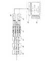
本実施の形態では図1のような回路構成を用いる。100は入力信号をRGB3原色信号に変換するRGB変換回路、101はRGB3原色映像信号を表示可能な階調数に制限するための階調制限回路、102は階調制限された映像信号から疑似的に入力映像を再現するための階調補正回路、103は前述のようにRGB3原色信号からW信号を生成し、RGBWの信号を出力する信号作成回路、104はフィールドメモリであり、一方に書きこむ間は他方からRGBWの順に読み出して、フィールドシーケンシャルディスプレイ105のソースドライバ106に入力する。フィールドシーケンシャルディスプレイ105は、1フィールドをRGBWの4つの期間に分割して表示する。信号作成回路103と階調制限回路101、階調補正回路102の順序が逆になっていることを除いて、従来の技術において説明した図7の回路構成と同一である。
【0023】
図2(a)に示すように、R=210,G=90,B=150となる映像信号がRGB変換回路から出力された場合、本回路構成では、まず白信号を作成する(図2(b))。このときRGBのうち最小の階調レベルであるG=90を白信号の値とし、RGBから90を減じたものをそれぞれの階調レベルとする。したがって、R=120、G=0,B=60,W=90となる。この値はまだ256階調での値であるため、階調制限回路および階調補正回路によって13階調での値(R=115,G=0,B=56,W=82)に変換され(図2(c))、これがフィールドシーケンシャル・カラー・ディスプレイにおいて表示される。
【0024】
本実施の形態では、図2(a)に示すように入力されたR=210,G=90,B=150が、最終的にR=115,G=0,B=56,W=82に変換されて表示されることを説明した。
【0025】
上述したように、図9(a)に示すように入力されたR=210,G=90,B=150が、最終的にR=115,G=0,B=82,W=82に変換されて表示されることを説明した。
【0026】
この両者では、最終的にディスプレイに表示される値はほぼ等しい。しかし、本実施の形態では画質の劣化は無く、従来のものでは画質が劣化する。これは、本実施の形態においては入力信号を疑似的に表現するために最適化された値(階調補正された値)をそのまま表現しているのに対し、従来の例では入力信号を疑似的に表現するために最適化された値とは異なる値を表示しているからである。階調補正は最適な輝度を持つ画素空間的にを配置することで疑似的な表現するので、それぞれの画素が定められた値と異なる値を表示してしまう場合には入力映像を疑似的に表現できない。
【0027】
したがって、本実施の形態で述べたように、入力信号からまず白信号を作成し、その後、RGBWの4つの信号でそれぞれ独立に階調制限、階調補正を行うことにより、従来と比して画質を劣化させずに入力映像を疑似的に表現することができる。
【0028】
(実施の形態2)
本実施の形態における回路構成を図3に示す。入力された映像信号をRGB変換回路300においてRGB3原色映像信号(256階調)に変換する。次に動き検出回路301において映像信号のうち動きのある部分を検出する。この動き検出回路301は動画部分を検出する動画検出部である。動き検出回路301においては、RGB原色映像信号のうちのいずれかで動きが検出された場合にその映像部分を動画部分と判定する。これはRGBそれぞれに対し独立に動きを検出した場合には、動画部分と静止画部分で処理を切りかえるために、例えばRが動画でG、Bが静止画であると判定した場合には、W信号を作成できないからである。
【0029】
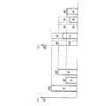
次に、セレクタ302により静止画部分は(a)で示した流れを通り、動画部分は(b)で示した流れを通る。静止画部分は階調制限回路304でディスプレにおいて表示可能な階調数に制限され、階調補正回路305で疑似的に入力映像信号を再現した後、信号作成回路303においてW信号を作成する。動画部分はまず信号作成回路306においてW信号を作成した後RGBWそれぞれで独立に階調制限回路307および階調補正回路308において処理される。セレクタからフィールドメモリの手前までの点線で囲った部分309が動画処理部である。
【0030】
これらの信号はいったんフィールドメモリ310に書きこまれた後、RGBWの順に読み出され、ソースドライバに書きこまれる。フィールドシーケンシャル・カラー・ディスプレイ311では1フィールド期間を4つの期間に分割し、RGBWの映像信号を順次表示する。
【0031】
誤差拡散処理は階調を制限した際の表示誤差を高い空間周波数に変調して表示する方式であり、ディザ処理は基本的に画像にノイズを加算する方式であるので、これらの階調補正を行うと、映像にザラツキやノイズ感がでる。白信号を生成してからRGBWの4枚の画像で階調補正を行う場合には、4回分のザラツキが加算され、RGBの3枚の画像で階調補正を行ってから白信号を生成する場合は3回分のザラツキが加算されることとなる。
【0032】
したがって、RGBの3枚の画像で階調補正を行ってから白信号を生成する方が、白信号を生成してからRGBWの4枚の画像で階調補正を行うよりもノイズ感が少ない。
【0033】
また、RGBの3枚の画像で階調補正を行ってからW信号を生成した場合、動画像を視線が追いかけて観測すると、RGBWの4つの信号は空間的にずれて観測されるため、入力映像信号は視覚的には再現されず、画質が大きく劣化する。ところが先にW信号を生成し、その後RGBWのそれぞれに対して独立に階調補正を行った場合は、RGBWのそれぞれの画像で空間的に最適な輝度の画素が配置され、単独で画像として成立しているためにRGBWの4つの信号が空間的にずれて観測されても画質の劣化が少ない。
【0034】
これらのことを鑑み、本実施の形態では、静止画部分についてはノイズ感が少ないようにRGB映像信号に階調補正を行ってから白信号を生成し、動画部分については、より画質の劣化が少なくなるように白信号を生成してからRGBW映像信号に階調補正を行っている。
【0035】
(実施の形態3)
入力映像信号が0〜255までの256階調であり、表示可能な階調数が0、1、3、7、13、23、37、56、82、115、155、202、255の13階調であるとする。また、RGB3原色信号から作成される他の1色は白であるとする。
【0036】
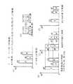
本実施の形態では図4のような回路構成を用いる。400は入力信号をRGB3原色信号に変換するRGB変換回路、401はRGB3原色映像信号を表示可能な階調数に制限するための階調制限回路、402は階調制限された映像信号から疑似的に入力映像を再現するための階調補正回路、403は前述のようにRGB3原色信号からW信号を生成し、RGBWの信号を出力する信号作成回路、404はフィールドメモリであり、一方に書きこむ間は他方からRGBWの順に読み出して、フィールドシーケンシャルディスプレイ405のソースドライバ406に入力する。フィールドシーケンシャルディスプレイ405は、1フィールドをRGBWの4つの期間に分割して表示する。
【0037】
この例では、信号作成回路403の後段に再度階調補正回路402があることをのぞいて、従来の技術において説明した図7の回路構成と同一である。
【0038】
図9(a)に示すように入力映像信号がR=210,G=90,B=150であるとき、最初の階調補正回路の後にはR=202,G=82,B=155となることが考えられる(図9(b))。ここから白信号を作成した場合にはR=120,G=0,B=73,W=82となる(図9(c))が、これらは表示可能な輝度レベルからずれている。したがって表示する際にもっとも近い値を選んだとしても、R=115,G=0,B=82,W=82となる(図9(d))。これをRGBに換算すると、R=197,G=82,B=164となり、最初に階調補正を行った際に決定された値とずれてしまう。
【0039】
本実施の形態ではここで再度階調補正を行うことにより、入力された映像に近い画像を表示することが可能である。
【0040】
【発明の効果】
以上のように本発明のシーケンシャル・カラー・ディスプレイ装置は、1フィールドを赤、緑、青、および他の1色の画像を表示する4つの期間に分割して表示するシーケンシャル・カラー・ディスプレイ装置であって、入力信号より生成された赤、緑、青、および他の1色の画像に対しそれぞれ独立に階調補正を行うことを特徴とするシーケンシャル・カラー・ディスプレイ装置であるので、動画像を追いかけて観測した際にもRGBWそれぞれの映像は空間内で必要な階調を疑似的に表現されているため、階調補正を行ってから他の1色の信号を生成した場合に比べて画質の劣化が少ない。また、表示可能な階調の並びが等間隔でない場合においても、階調補正後の映像信号、すなわち表示すべき値と実際に表示される映像が一致する。
【0041】
また、1フィールドを赤、緑、青、およびこれ以外の他の1色の画像を4つの期間に分割して表示するディスプレイ装置であって、赤緑青3原色に階調補正を行った後、前記他の1色の画像を作成し、赤、緑、青および前記他の一色の画像信号に対してそれぞれ独立に階調補正処理を行うことにより、表示可能な階調の並びが等間隔でない場合においても、階調補正後の映像信号、すなわち表示すべき値と実際に表示される映像が一致する。
【0042】
また、3原色に対応する画像信号から他の1色の信号を作成する信号作成部と、画像信号に対し階調補正を行う階調補正部と、動画部分を検出して動画部分と静止画部分で信号作成部と階調補正部の処理順序を変更する動画処理部を有することにより、誤差拡散処理やディザ処理を行うと、映像にノイズ感がでる。RGBの3枚の画像で階調補正を行ってから他の1色の信号を生成した方が、他の1色の信号を生成してからRGBWの4枚の画像で階調補正を行うよりもノイズ感が少ない。したがって、動画かまたは静止画かを区別して処理することにより、最適に表示画像が得られる。
【0043】
さらに、静止画部分においては3原色に対応する画像信号に階調補正部で階調補正を行った後、信号作成部において他の1色の信号を作成することにより、静止画部分では階調補正によるノイズ感の少ない映像が得られる。また、動画部分においては3原色に対応する画像信号から信号作成部において他の1色の信号を作成した後、階調補正部において赤、緑、青、および他の1色のそれぞれの画像信号に対して独立に階調補正を行うことにより、動画像を追いかけて観測した際にもRGBWそれぞれの映像は空間内で必要な階調を疑似的に表現されているため、階調補正を行ってから他の1色の信号を生成した場合に比べて画質の劣化が少ない。
【図面の簡単な説明】
【図1】本発明の実施の形態1によるシーケンシャル・カラー・ディスプレイ装置の回路構成図
【図2】同装置における階調補正説明図
【図3】本発明の実施の形態2によるシーケンシャル・カラー・ディスプレイ装置の回路構成図
【図4】本発明の実施の形態3によるシーケンシャル・カラー・ディスプレイ装置の回路構成図
【図5】シーケンシャル・カラー・ディスプレイ表示方法を説明するための説明図
【図6】シーケンシャル・カラー・ディスプレイ装置における白信号生成方法の説明図
【図7】従来のシーケンシャル・カラー・ディスプレイ装置の回路構成図
【図8】従来のシーケンシャル・カラー・ディスプレイ装置における階調補正説明図
【図9】従来のシーケンシャル・カラー・ディスプレイにおける表示可能な階調が等間隔では無い場合の階調補正説明図
【符号の説明】
100、300、400 RGB変換回路
101、304、307、401 階調制限回路
102、305、308、402 階調補正回路
103、303、306、403 信号作成回路
104、310、404 フィールドメモリ
105、311、405 シーケンシャル・カラー・ディスプレイ
301 動き検出回路
302 セレクタ
309 動画処理部[0001]
BACKGROUND OF THE INVENTION
The present invention relates to a sequential color display device.
[0002]
[Prior art]
In this type of sequential color display device, as shown in FIG. 5, a display device that displays an image by dividing one field into four periods for displaying red, green, blue, and white is disclosed in Japanese Patent Laid-Open No. 09-90916. Known in the Gazette.
[0003]
In this conventional apparatus, for example, as shown in FIGS. 6A and 6B, the RGB three primary color video signals (256 gradations) are subtracted from the minimum gradation (G: 96 in FIG. 6). Are white (W) video signals.
[0004]
In a display device with a small number of displayable gradations, a circuit configuration as shown in FIG. 7 is used, and an input video signal is expressed in a pseudo manner with a small number of gradations by error diffusion processing or dither processing. An
[0005]
In the above circuit, for example, when the input video signal is R = 210, G = 90, and B = 150 as shown in FIG. 8A, after gradation correction, as shown in FIG. 8B, R = It can be considered that 224, G = 96, and B = 160. When a white signal is created from this, as shown in FIG. 8C, R = 128, G = 0, B = 64, and W = 96, which are displayed on the display.
[0006]
[Problems to be solved by the invention]
However, when the W video signal is generated after tone correction is performed on the RGB three primary color video signal, the image deteriorates in the moving image for the following reason.
[0007]
The error diffusion process is a technique for displaying a desired gradation in a pseudo manner by diffusing an error between an input video signal and an actually displayed value to surrounding pixels at a predetermined ratio. The dither processing is a method in which a dither matrix having a predetermined number of rows and columns is added to a video signal, and then a value exceeding a predetermined threshold is moved up.
[0008]
The common point of these methods is that a desired gradation is obtained by spatially arranging a plurality of pixels having optimum luminance according to a predetermined rule.
[0009]
When gradation correction is performed by error diffusion processing or dither processing on each of the RGB three primary color video signals, and then a W video signal is created, since each RGBW alone does not represent a gradation, four RGBW images The input video can be represented in a pseudo manner only when the two completely overlap. However, when a moving image is observed following the line of sight, the four RGBW images are observed with a spatial shift, so the input video signal is not correctly represented. The image quality also deteriorates when the displayable gradation levels are not equally spaced as described above.
[0010]
The input video signal has 256 gradations from 0 to 255, and the number of gradations that can be displayed is 0, 1, 3, 7, 13, 23, 37, 56, 82, 115, 155, 202, 255. Consider the key.
[0011]
As shown in FIG. 9A, when the input video signal is R = 210, G = 90, and B = 150, it can be considered that R = 202, G = 82, and B = 155 after error diffusion ( FIG. 9B). When a white signal is created from this, R = 120, G = 0, B = 73, and W = 82 (FIG. 9C), but these are deviated from the displayable luminance level. Therefore, even if the closest value is selected for display, R = 115, G = 0, B = 82, and W = 82 (FIG. 9D). When this is converted to RGB, R = 197, G = 82, and B = 164, which deviate from the values determined by error diffusion. The value determined by error diffusion is the optimum value for pseudo reproduction of the input video with a small number of gradations. If it deviates from this value, the input video is not reproduced and the image quality deteriorates. To do.
[0012]
The present invention has been made in view of these problems, and provides a sequential color display device with little image quality degradation.
[0013]
[Means for Solving the Problems]
In order to solve the above-described problems, a sequential color display device according to the present invention includesa signal generation unit that generates a signal of another color from an image signal corresponding to three primary colors of red, green, and blue, and an image signal. A gradation correction unit that performs gradation correction on the image, a moving image detection unit that detects a moving image part, and a moving image processing unit that changes a processing order of the signal generation unit and the gradation correction unit in the moving image part and the still image part. This is a sequential color display device.
[0014]
DETAILED DESCRIPTION OF THE INVENTION
A sequential color display device according to a first aspect of the present invention includesa signal generation unit that generates a signal of another color from an image signal corresponding to three primary colors of red, green, and blue, and a step for the image signal. A tone correction unit that performs tone correction, a moving image detection unit that detects a moving image part, and a moving image processing unit that changes the processing order of the signal generation unit and the gradation correction unit in the moving image part and the still image part, This is a sequential color display device. When error diffusion processing or dither processing is performed, a sense of noise appears in the image. When tone correction is performed on three RGB images and then another color signal is generated, tone correction is performed on four RGBW images after the other color signal is generated. There is little noise. Therefore, a display image can be optimally obtained by processing whether it is a moving image or a still image.
[0017]
In the sequential color display device according to thesecond aspect of the present invention, the tone correction unit performs tone correction on the image signal corresponding to the three primary colors in the still image portion, and then the signal generation unit performs another one. Since it is a sequential color display device characterized by generating a color signal, an image with less noise feeling due to gradation correction can be obtained in the still image portion.
[0018]
In the sequential color display device according to thethird aspect of the present invention, in the moving image portion, the signal generating unit generates another signal of one color from the image signals corresponding to the three primary colors, and then the red tone is corrected in the gradation correcting unit. , Green, blue, and other one color image signal is a sequential color display device characterized by performing gradation correction independently, so even when chasing a moving image Since each RGBW image has a pseudo representation of the necessary gradation in the space, there is less degradation in image quality than when one color signal is generated after gradation correction.
[0019]
It determines that sequential color display apparatus according to claim4 of the present invention, the video detector, red, green, which is a moving part of the movement is detected portion in one of theimages signals of blue A sequential color display device. For example, if motion is detected independently for each of RGB, in order to switch the processing order of signal generation and gradation correction between the moving image portion and the still image portion, for example, R is a moving image and G and B are still images. This is because the W signal cannot be created when it is determined that the signal is.
[0020]
Hereinafter, a sequential color display device according to an embodiment of the present invention will be described with reference to FIGS.
[0021]
(Embodiment 1)
The input video signal has 256 gradations from 0 to 255, and the number of gradations that can be displayed is 0, 1, 3, 7, 13, 23, 37, 56, 82, 115, 155, 202, 255. Suppose that it is a key. Further, it is assumed that the other color created from the RGB three primary color signals is white.
[0022]
In this embodiment, a circuit configuration as shown in FIG. 1 is used.
[0023]
As shown in FIG. 2A, when a video signal with R = 210, G = 90, and B = 150 is output from the RGB conversion circuit, the circuit configuration first creates a white signal (FIG. 2 ( b)). At this time, G = 90, which is the minimum gradation level of RGB, is set as the value of the white signal, and the value obtained by subtracting 90 from RGB is set as the respective gradation level. Therefore, R = 120, G = 0, B = 60, and W = 90. Since this value is still a value with 256 gradations, it is converted into a value with 13 gradations (R = 115, G = 0, B = 56, W = 82) by the gradation limiting circuit and the gradation correction circuit. (FIG. 2 (c)), which is displayed on a field sequential color display.
[0024]
In this embodiment, R = 210, G = 90, and B = 150 input as shown in FIG. 2A finally become R = 115, G = 0, B = 56, and W = 82. Explained that converted and displayed.
[0025]
As described above, R = 210, G = 90, and B = 150 input as shown in FIG. 9A are finally converted to R = 115, G = 0, B = 82, and W = 82. Explained that it will be displayed.
[0026]
In both cases, the values finally displayed on the display are substantially equal. However, there is no deterioration in image quality in the present embodiment, and the image quality is deteriorated in the conventional one. In the present embodiment, the values optimized for representing the input signal in a pseudo manner (values subjected to gradation correction) are expressed as they are, whereas in the conventional example, the input signal is simulated. This is because a value different from the value optimized for the purpose of expression is displayed. Gradation correction is expressed in a pseudo manner by arranging the pixel space with the optimal brightness, so if each pixel displays a value different from the specified value, the input video is simulated I can't express it.
[0027]
Therefore, as described in the present embodiment, a white signal is first created from an input signal, and then gradation limitation and gradation correction are performed independently on each of the four RGBW signals. It is possible to simulate the input video without degrading the image quality.
[0028]
(Embodiment 2)
FIG. 3 shows a circuit configuration in this embodiment. The input video signal is converted into an RGB three primary color video signal (256 gradations) by the
[0029]
Next, by the
[0030]
These signals are once written in the
[0031]
The error diffusion process is a method of displaying the display error when the gradation is limited by modulating the display error to a high spatial frequency, and the dither process is basically a method of adding noise to the image. When I do it, there is a feeling of roughness and noise in the video. When gradation correction is performed on four RGBW images after generating a white signal, four times of roughness are added, and gradation correction is performed on the three RGB images before generating the white signal. In this case, three times of roughness will be added.
[0032]
Therefore, generating a white signal after performing tone correction on three RGB images has less noise than generating a white signal and then performing tone correction on four RGBW images.
[0033]
In addition, when the W signal is generated after gradation correction is performed on the three RGB images, if the moving image is observed following the line of sight, the four RGBW signals are observed in a spatially shifted manner. The video signal is not visually reproduced and the image quality is greatly degraded. However, if the W signal is generated first and then the tone correction is performed independently for each of RGBW, pixels having the optimal brightness are arranged in each RGBW image, and the image is formed independently. Therefore, even if four RGBW signals are observed with spatial deviation, image quality is hardly deteriorated.
[0034]
In view of these points, in the present embodiment, a white signal is generated after tone correction is performed on the RGB video signal so that there is less noise in the still image portion, and the image quality is further deteriorated in the moving image portion. After the white signal is generated so as to decrease, gradation correction is performed on the RGBW video signal.
[0035]
(Embodiment 3)
The input video signal has 256 gradations from 0 to 255, and the number of gradations that can be displayed is 0, 1, 3, 7, 13, 23, 37, 56, 82, 115, 155, 202, 255. Suppose that it is a key. Further, it is assumed that the other color created from the RGB three primary color signals is white.
[0036]
In this embodiment, a circuit configuration as shown in FIG. 4 is used.
[0037]
In this example, the circuit configuration is the same as the circuit configuration of FIG.
[0038]
As shown in FIG. 9A, when the input video signal is R = 210, G = 90, and B = 150, R = 202, G = 82, and B = 155 after the first gradation correction circuit. (FIG. 9B). When a white signal is created from this, R = 120, G = 0, B = 73, and W = 82 (FIG. 9C), but these are deviated from the displayable luminance level. Therefore, even if the closest value is selected for display, R = 115, G = 0, B = 82, and W = 82 (FIG. 9D). When this is converted to RGB, R = 197, G = 82, and B = 164, which deviate from the values determined when the gradation correction is first performed.
[0039]
In this embodiment, by performing gradation correction again here, it is possible to display an image close to the input video.
[0040]
【Effect of the invention】
As described above, the sequential color display device of the present invention is a sequential color display device that displays one field divided into four periods for displaying red, green, blue, and other one color images. The sequential color display device is characterized in that gradation correction is performed independently for each of the red, green, blue, and other one color images generated from the input signal. When chasing and observing, each RGBW image is a pseudo-representation of the necessary gradation in the space, so the image quality is higher than when one color signal is generated after gradation correction. There is little deterioration. Even when the displayable gradations are not arranged at equal intervals, the image signal after gradation correction, that is, the value to be displayed matches the actually displayed image.
[0041]
Further, the display device displays one field of red, green, blue, and another one color image divided into four periods, and after performing gradation correction on the three primary colors of red, green, and blue, By creating an image of the other color and independently performing gradation correction processing on the image signals of red, green, blue and the other color, the arrangement of displayable gradations is not equal. Even in this case, the video signal after gradation correction, that is, the value to be displayed matches the video that is actually displayed.
[0042]
In addition, a signal creation unit that creates a signal of one color from the image signal corresponding to the three primary colors, a tone correction unit that performs tone correction on the image signal, a moving image portion, and a moving image portion and a still image By having a moving image processing unit that changes the processing order of the signal generation unit and the gradation correction unit in a part, when an error diffusion process or a dither process is performed, a sense of noise appears in the video. When tone correction is performed on three RGB images and then another color signal is generated, tone correction is performed on four RGBW images after the other color signal is generated. There is little noise. Therefore, a display image can be optimally obtained by processing whether it is a moving image or a still image.
[0043]
Further, in the still image portion, the tone correction unit performs tone correction on the image signal corresponding to the three primary colors, and then the signal generation unit generates another one-color signal. An image with less noise by correction can be obtained. Further, in the moving image portion, after another signal of one color is generated by the signal generating unit from the image signal corresponding to the three primary colors, each of the image signals of red, green, blue, and other one color is generated by the gradation correcting unit. By independently performing gradation correction on the image, even when the chase of the moving image is followed, the RGBW images are simulated in a pseudo manner to represent the necessary gradation in the space. Compared with the case where the other color signal is generated, the image quality is less deteriorated.
[Brief description of the drawings]
FIG. 1 is a circuit configuration diagram of a sequential color display device according to a first embodiment of the present invention. FIG. 2 is an explanatory diagram of gradation correction in the device. FIG. 3 is a sequential color display device according to a second embodiment of the present invention. FIG. 4 is a circuit configuration diagram of a sequential color display device according to a third embodiment of the present invention. FIG. 5 is an explanatory diagram for explaining a sequential color display display method. FIG. 7 is a circuit configuration diagram of a conventional sequential color display device. FIG. 8 is an explanatory diagram of gradation correction in a conventional sequential color display device. 9 The displayable gradation in the conventional sequential color display is equal. Gradation correction explanatory view when not in [Description of symbols]
100, 300, 400
Claims (4)
Translated fromJapanesePriority Applications (1)
| Application Number | Priority Date | Filing Date | Title |
|---|---|---|---|
| JP2001266987AJP4892804B2 (en) | 2001-09-04 | 2001-09-04 | Sequential color display device |
Applications Claiming Priority (1)
| Application Number | Priority Date | Filing Date | Title |
|---|---|---|---|
| JP2001266987AJP4892804B2 (en) | 2001-09-04 | 2001-09-04 | Sequential color display device |
Publications (2)
| Publication Number | Publication Date |
|---|---|
| JP2003076341A JP2003076341A (en) | 2003-03-14 |
| JP4892804B2true JP4892804B2 (en) | 2012-03-07 |
Family
ID=19093186
Family Applications (1)
| Application Number | Title | Priority Date | Filing Date |
|---|---|---|---|
| JP2001266987AExpired - Fee RelatedJP4892804B2 (en) | 2001-09-04 | 2001-09-04 | Sequential color display device |
Country Status (1)
| Country | Link |
|---|---|
| JP (1) | JP4892804B2 (en) |
Families Citing this family (6)
| Publication number | Priority date | Publication date | Assignee | Title |
|---|---|---|---|---|
| JP2005055658A (en)* | 2003-08-04 | 2005-03-03 | Seiko Epson Corp | Electro-optical device, driving method thereof, and electronic apparatus |
| JP4577549B2 (en)* | 2004-01-22 | 2010-11-10 | ソニー株式会社 | Image display device |
| KR100637436B1 (en) | 2004-06-03 | 2006-10-20 | 삼성에스디아이 주식회사 | LCD and its driving method |
| US7932883B2 (en)* | 2005-04-21 | 2011-04-26 | Koninklijke Philips Electronics N.V. | Sub-pixel mapping |
| US9177514B2 (en) | 2011-01-20 | 2015-11-03 | Sharp Kabushiki Kaisha | Image display apparatus and image display method |
| US9208731B2 (en)* | 2012-10-30 | 2015-12-08 | Pixtronix, Inc. | Display apparatus employing frame specific composite contributing colors |
Family Cites Families (4)
| Publication number | Priority date | Publication date | Assignee | Title |
|---|---|---|---|---|
| JPH05241551A (en)* | 1991-11-07 | 1993-09-21 | Canon Inc | Image processor |
| JPH11327492A (en)* | 1998-05-20 | 1999-11-26 | Mitsubishi Electric Corp | Screen sequential color image display apparatus and screen sequential color image display method |
| JP3255358B2 (en)* | 1998-11-19 | 2002-02-12 | 日本電気株式会社 | Gradation conversion circuit and image display device |
| JP3766274B2 (en)* | 2000-12-21 | 2006-04-12 | 株式会社東芝 | Time-division color display device and display method |
- 2001
- 2001-09-04JPJP2001266987Apatent/JP4892804B2/ennot_activeExpired - Fee Related
Also Published As
| Publication number | Publication date |
|---|---|
| JP2003076341A (en) | 2003-03-14 |
Similar Documents
| Publication | Publication Date | Title |
|---|---|---|
| CN101562002B (en) | Controller, hold-type display device, electronic apparatus and signal adjusting method | |
| JP2003288058A (en) | Image display method and image display device | |
| CN103325330B (en) | Image processor and image processing method | |
| JP2000188702A (en) | Video signal processing circuit for matrix type display device | |
| JP2006215534A (en) | Image display device | |
| JP4892804B2 (en) | Sequential color display device | |
| JP2003338929A (en) | Image processing method and image processing apparatus | |
| JP2005024708A (en) | Gradation-multiplied signal processor | |
| KR20090116166A (en) | Method and apparatus for processing video data of plasma display panel | |
| JP3785922B2 (en) | Error diffusion processing method for display device | |
| US8125436B2 (en) | Pixel dithering driving method and timing controller using the same | |
| JP4182470B2 (en) | Video display device and video signal processing method used therefor | |
| KR100888577B1 (en) | Method of processing error diffusion in a display device | |
| JP2000148068A (en) | Circuit and method for processing video signal of matrix type display device | |
| US9210390B2 (en) | Poly-phase frame modulation system | |
| US7443365B2 (en) | Display unit and display method | |
| JP2008250065A (en) | Color display device and color display method | |
| JP3625192B2 (en) | Video signal processing circuit and method for matrix display device | |
| JP4165590B2 (en) | Image data processing device, image display device, driving image data generation method, and computer program | |
| JP2006154576A (en) | Gradation correction apparatus and gradation correction method | |
| JP3541700B2 (en) | Video signal adjusting circuit and method for matrix display device | |
| WO2001093239A1 (en) | Number-of-gradation-levels decreasing method, image displaying method, and image display | |
| JP3593799B2 (en) | Error diffusion circuit of multiple screen display device | |
| JP3675298B2 (en) | Display device | |
| JP2002091375A (en) | Method for processing gradation display of plasma display panel |
Legal Events
| Date | Code | Title | Description |
|---|---|---|---|
| A621 | Written request for application examination | Free format text:JAPANESE INTERMEDIATE CODE: A621 Effective date:20080804 | |
| RD01 | Notification of change of attorney | Free format text:JAPANESE INTERMEDIATE CODE: A7421 Effective date:20080912 | |
| RD01 | Notification of change of attorney | Free format text:JAPANESE INTERMEDIATE CODE: A7421 Effective date:20091119 | |
| A977 | Report on retrieval | Free format text:JAPANESE INTERMEDIATE CODE: A971007 Effective date:20110809 | |
| A131 | Notification of reasons for refusal | Free format text:JAPANESE INTERMEDIATE CODE: A131 Effective date:20110823 | |
| A521 | Written amendment | Free format text:JAPANESE INTERMEDIATE CODE: A523 Effective date:20111024 | |
| TRDD | Decision of grant or rejection written | ||
| A01 | Written decision to grant a patent or to grant a registration (utility model) | Free format text:JAPANESE INTERMEDIATE CODE: A01 Effective date:20111122 | |
| A01 | Written decision to grant a patent or to grant a registration (utility model) | Free format text:JAPANESE INTERMEDIATE CODE: A01 | |
| A61 | First payment of annual fees (during grant procedure) | Free format text:JAPANESE INTERMEDIATE CODE: A61 Effective date:20111205 | |
| FPAY | Renewal fee payment (event date is renewal date of database) | Free format text:PAYMENT UNTIL: 20150106 Year of fee payment:3 | |
| LAPS | Cancellation because of no payment of annual fees |