JP4892641B2 - Fan assembly - Google Patents
Fan assemblyDownload PDFInfo
- Publication number
- JP4892641B2 JP4892641B2JP2011203122AJP2011203122AJP4892641B2JP 4892641 B2JP4892641 B2JP 4892641B2JP 2011203122 AJP2011203122 AJP 2011203122AJP 2011203122 AJP2011203122 AJP 2011203122AJP 4892641 B2JP4892641 B2JP 4892641B2
- Authority
- JP
- Japan
- Prior art keywords
- base
- fan assembly
- stand
- main body
- interlock
- Prior art date
- Legal status (The legal status is an assumption and is not a legal conclusion. Google has not performed a legal analysis and makes no representation as to the accuracy of the status listed.)
- Expired - Fee Related
Links
- 238000003825pressingMethods0.000claimsdescription4
- 230000000903blocking effectEffects0.000claimsdescription2
- 230000002401inhibitory effectEffects0.000claims1
- 238000005096rolling processMethods0.000description15
- 230000002093peripheral effectEffects0.000description13
- 230000007246mechanismEffects0.000description10
- 238000001816coolingMethods0.000description6
- 230000000694effectsEffects0.000description6
- 239000012530fluidSubstances0.000description4
- 125000006850spacer groupChemical group0.000description4
- 239000006260foamSubstances0.000description3
- 238000000034methodMethods0.000description3
- 230000004044responseEffects0.000description3
- OKTJSMMVPCPJKN-UHFFFAOYSA-NCarbonChemical compound[C]OKTJSMMVPCPJKN-UHFFFAOYSA-N0.000description2
- 230000009471actionEffects0.000description2
- 229910052799carbonInorganic materials0.000description2
- 230000005484gravityEffects0.000description2
- 230000006698inductionEffects0.000description2
- 238000010079rubber tappingMethods0.000description2
- 241000954177Bangana arizaSpecies0.000description1
- 206010020751HypersensitivityDiseases0.000description1
- 230000004913activationEffects0.000description1
- 230000007815allergyEffects0.000description1
- 230000008901benefitEffects0.000description1
- 238000004140cleaningMethods0.000description1
- 230000007423decreaseEffects0.000description1
- 238000007599dischargingMethods0.000description1
- 238000006073displacement reactionMethods0.000description1
- 239000003344environmental pollutantSubstances0.000description1
- 238000001704evaporationMethods0.000description1
- 230000008020evaporationEffects0.000description1
- NJPPVKZQTLUDBO-UHFFFAOYSA-NnovaluronChemical compoundC1=C(Cl)C(OC(F)(F)C(OC(F)(F)F)F)=CC=C1NC(=O)NC(=O)C1=C(F)C=CC=C1FNJPPVKZQTLUDBO-UHFFFAOYSA-N0.000description1
- 230000010355oscillationEffects0.000description1
- 231100000719pollutantToxicity0.000description1
- 238000009827uniform distributionMethods0.000description1
- 238000011144upstream manufacturingMethods0.000description1
- 238000009423ventilationMethods0.000description1
Images


Classifications
- F—MECHANICAL ENGINEERING; LIGHTING; HEATING; WEAPONS; BLASTING
- F04—POSITIVE - DISPLACEMENT MACHINES FOR LIQUIDS; PUMPS FOR LIQUIDS OR ELASTIC FLUIDS
- F04D—NON-POSITIVE-DISPLACEMENT PUMPS
- F04D25/00—Pumping installations or systems
- F—MECHANICAL ENGINEERING; LIGHTING; HEATING; WEAPONS; BLASTING
- F24—HEATING; RANGES; VENTILATING
- F24F—AIR-CONDITIONING; AIR-HUMIDIFICATION; VENTILATION; USE OF AIR CURRENTS FOR SCREENING
- F24F13/00—Details common to, or for air-conditioning, air-humidification, ventilation or use of air currents for screening
- F24F13/32—Supports for air-conditioning, air-humidification or ventilation units
- F—MECHANICAL ENGINEERING; LIGHTING; HEATING; WEAPONS; BLASTING
- F04—POSITIVE - DISPLACEMENT MACHINES FOR LIQUIDS; PUMPS FOR LIQUIDS OR ELASTIC FLUIDS
- F04D—NON-POSITIVE-DISPLACEMENT PUMPS
- F04D25/00—Pumping installations or systems
- F04D25/02—Units comprising pumps and their driving means
- F04D25/08—Units comprising pumps and their driving means the working fluid being air, e.g. for ventilation
- F—MECHANICAL ENGINEERING; LIGHTING; HEATING; WEAPONS; BLASTING
- F04—POSITIVE - DISPLACEMENT MACHINES FOR LIQUIDS; PUMPS FOR LIQUIDS OR ELASTIC FLUIDS
- F04D—NON-POSITIVE-DISPLACEMENT PUMPS
- F04D29/00—Details, component parts, or accessories
- F04D29/26—Rotors specially for elastic fluids
- F04D29/32—Rotors specially for elastic fluids for axial flow pumps
- F04D29/38—Blades
- F—MECHANICAL ENGINEERING; LIGHTING; HEATING; WEAPONS; BLASTING
- F04—POSITIVE - DISPLACEMENT MACHINES FOR LIQUIDS; PUMPS FOR LIQUIDS OR ELASTIC FLUIDS
- F04D—NON-POSITIVE-DISPLACEMENT PUMPS
- F04D29/00—Details, component parts, or accessories
- F04D29/40—Casings; Connections of working fluid
- F04D29/403—Casings; Connections of working fluid especially adapted for elastic fluid pumps
- F—MECHANICAL ENGINEERING; LIGHTING; HEATING; WEAPONS; BLASTING
- F04—POSITIVE - DISPLACEMENT MACHINES FOR LIQUIDS; PUMPS FOR LIQUIDS OR ELASTIC FLUIDS
- F04D—NON-POSITIVE-DISPLACEMENT PUMPS
- F04D29/00—Details, component parts, or accessories
- F04D29/40—Casings; Connections of working fluid
- F04D29/42—Casings; Connections of working fluid for radial or helico-centrifugal pumps
- F04D29/4206—Casings; Connections of working fluid for radial or helico-centrifugal pumps especially adapted for elastic fluid pumps
- F04D29/4226—Fan casings
- F—MECHANICAL ENGINEERING; LIGHTING; HEATING; WEAPONS; BLASTING
- F04—POSITIVE - DISPLACEMENT MACHINES FOR LIQUIDS; PUMPS FOR LIQUIDS OR ELASTIC FLUIDS
- F04D—NON-POSITIVE-DISPLACEMENT PUMPS
- F04D29/00—Details, component parts, or accessories
- F04D29/60—Mounting; Assembling; Disassembling
- F—MECHANICAL ENGINEERING; LIGHTING; HEATING; WEAPONS; BLASTING
- F04—POSITIVE - DISPLACEMENT MACHINES FOR LIQUIDS; PUMPS FOR LIQUIDS OR ELASTIC FLUIDS
- F04D—NON-POSITIVE-DISPLACEMENT PUMPS
- F04D29/00—Details, component parts, or accessories
- F04D29/60—Mounting; Assembling; Disassembling
- F04D29/601—Mounting; Assembling; Disassembling specially adapted for elastic fluid pumps
- F—MECHANICAL ENGINEERING; LIGHTING; HEATING; WEAPONS; BLASTING
- F04—POSITIVE - DISPLACEMENT MACHINES FOR LIQUIDS; PUMPS FOR LIQUIDS OR ELASTIC FLUIDS
- F04D—NON-POSITIVE-DISPLACEMENT PUMPS
- F04D29/00—Details, component parts, or accessories
- F04D29/60—Mounting; Assembling; Disassembling
- F04D29/62—Mounting; Assembling; Disassembling of radial or helico-centrifugal pumps
- F04D29/624—Mounting; Assembling; Disassembling of radial or helico-centrifugal pumps especially adapted for elastic fluid pumps
- F04D29/626—Mounting or removal of fans
- F—MECHANICAL ENGINEERING; LIGHTING; HEATING; WEAPONS; BLASTING
- F04—POSITIVE - DISPLACEMENT MACHINES FOR LIQUIDS; PUMPS FOR LIQUIDS OR ELASTIC FLUIDS
- F04F—PUMPING OF FLUID BY DIRECT CONTACT OF ANOTHER FLUID OR BY USING INERTIA OF FLUID TO BE PUMPED; SIPHONS
- F04F5/00—Jet pumps, i.e. devices in which flow is induced by pressure drop caused by velocity of another fluid flow
- F04F5/14—Jet pumps, i.e. devices in which flow is induced by pressure drop caused by velocity of another fluid flow the inducing fluid being elastic fluid
- F04F5/16—Jet pumps, i.e. devices in which flow is induced by pressure drop caused by velocity of another fluid flow the inducing fluid being elastic fluid displacing elastic fluids
- F—MECHANICAL ENGINEERING; LIGHTING; HEATING; WEAPONS; BLASTING
- F24—HEATING; RANGES; VENTILATING
- F24F—AIR-CONDITIONING; AIR-HUMIDIFICATION; VENTILATION; USE OF AIR CURRENTS FOR SCREENING
- F24F7/00—Ventilation
- F24F7/007—Ventilation with forced flow
Landscapes
- Engineering & Computer Science (AREA)
- Mechanical Engineering (AREA)
- General Engineering & Computer Science (AREA)
- Chemical & Material Sciences (AREA)
- Combustion & Propulsion (AREA)
- Physics & Mathematics (AREA)
- Fluid Mechanics (AREA)
- Structures Of Non-Positive Displacement Pumps (AREA)
- Jet Pumps And Other Pumps (AREA)
Description
Translated fromJapanese本発明は、ファン又は扇風機組立体に関する。特に、本発明は、部屋、オフィス又は他の家庭環境において空気の循環及び送風を生じさせる家庭用ファン、例えば卓上扇風機に関する(なお、本明細書において、ファンと扇風機は、用語として区別なく用いられている)。 The present invention relates to a fan or a fan assembly. In particular, the present invention relates to a domestic fan, such as a tabletop fan, that causes air circulation and ventilation in a room, office, or other home environment. (In this specification, the terms fan and fan are used interchangeably. ing).
従来の家庭用ファンは、典型的には、軸を中心に回転する一組の羽根又は翼と、空気流を生成するために一組の羽根を回転させるための駆動装置とを有する。空気流の動き及び循環は、風速冷却又はそよ風を精製し、その結果、使用者は対流および蒸発によって熱が発散されるので、冷却効果を得られる。 Conventional household fans typically have a set of blades or wings that rotate about an axis and a drive for rotating the set of blades to generate an air flow. The movement and circulation of the air flow refines the wind speed cooling or the breeze so that the user can obtain a cooling effect as heat is dissipated by convection and evaporation.
かかるファンは、種々の寸法形状で入手できる。例えば、天井ファンは、直径が少なくとも1mの場合があり、通常、天井から吊り下げられた状態で取り付けられていて、下向きの空気流を生じさせ、それにより部屋を冷やすようになっている。他方、卓上ファンは、直径が約30cmの場合が多く、通常は自立型且つ携帯可能である。他形式のファンは、床に取り付け可能であり又は壁に設置できる。米国意匠特許第103,476号明細書及び米国特許第1,767,060号明細書に開示されているファンは、机又はテーブル上に立てて置くのに適している。 Such fans are available in various sizes and shapes. For example, a ceiling fan may have a diameter of at least 1 m and is usually mounted suspended from the ceiling, creating a downward air flow, thereby cooling the room. On the other hand, desk fans are often about 30 cm in diameter, and are usually free standing and portable. Other types of fans can be mounted on the floor or installed on the wall. The fans disclosed in US Pat. No. 103,476 and US Pat. No. 1,767,060 are suitable for standing on a desk or table.
この種の構成の欠点は、回転翼又は羽根により生じる空気流が一般的に言って一様ではないということにある。これは、ファンの羽根表面又は外方に向いた表面全体におけるばらつきに起因している。これらばらつきの程度は、製品毎に様々な場合があり、1つの個別ファンヒータと別の個別ファンヒータとでも異なる場合がある。これらのばらつきの結果として、むらのある又は「風向きの変わりやすい」空気流が発生し、かかる空気流は、空気の一連のパルスとして感じられる場合があると共にユーザにとって不快な場合がある。もう1つの欠点は、ファンにより生じる冷却効果がユーザからの距離につれて減少することにある。このことは、ユーザがファンの冷却効果を体験するにはファンをユーザに近接して配置しなければならないということを意味している。 The disadvantage of this type of configuration is that the air flow produced by the rotor blades or blades is generally not uniform. This is due to variations in the fan blade surface or the entire outwardly facing surface. The degree of variation may vary from product to product, and may vary between one individual fan heater and another individual fan heater. As a result of these variations, a non-uniform or “wind-changing” air flow may occur that may be felt as a series of pulses of air and may be uncomfortable for the user. Another disadvantage is that the cooling effect caused by the fan decreases with distance from the user. This means that the user must place the fan close to the user to experience the cooling effect of the fan.
ファンの出口を回転させて空気流が部屋の広い領域にわたってスイープ(弧を描いて放出)されるようにするために揺動又は首振り機構体が採用される場合がある。揺動機構体は、ユーザの感じる空気流の質及び一様性を幾分改良することができるが、特徴的な「風向きの変わりやすい」空気流が生じることに変わりはない。 A swing or swing mechanism may be employed to rotate the fan outlet so that airflow is swept across a large area of the room. The oscillating mechanism can somewhat improve the quality and uniformity of the airflow felt by the user, but it still produces the characteristic “wind direction variable” airflow.
例えば上述したファンをユーザの近くに配置することは、ファンの形状及び構造が嵩張っていることがユーザの作業空間領域の相当な部分がファンによって占められるのでいつでも可能であるというわけではない。 For example, disposing the above-described fan close to the user is not always possible because the fan occupies a substantial portion of the user's work space area that makes the fan shape and structure bulky.
ファンの中には、ユーザに空気をファンから放出する方向を調節するオプションを提供する例えば米国特許第5,609,473号明細書に記載されているようなファンがある。米国特許第5,609,473号明細書の開示内容によれば、ファンは、ベース及び各々がベースのそれぞれ対応の端部から直立した1対のヨークを有している。ファンの外側本体は、モータ及び1組の回転翼又は羽根を収容している。外側本体は、ベースに対して回動可能であるようにヨークに固定されている。ファン本体は、ベースに対して、全体として垂直の非傾動位置から傾斜した傾動位置まで揺動可能である。このように、ファンから放出される空気流の方向を変えることができる。 Some fans, such as those described in US Pat. No. 5,609,473, provide the user with the option of adjusting the direction in which air is discharged from the fan. According to the disclosure of US Pat. No. 5,609,473, the fan has a base and a pair of yokes each upstanding from a respective corresponding end of the base. The outer body of the fan houses a motor and a set of rotor blades or vanes. The outer body is fixed to the yoke so as to be rotatable with respect to the base. The fan main body can swing from a non-tilting position perpendicular to the base to a tilting position inclined. In this way, the direction of the air flow discharged from the fan can be changed.
かかるファンでは、ベースに対するファンの本体の位置を固定するために固定機構体を採用するのが良い。固定機構体は、特に老人又は不器用なユーザにとって使用するのが困難な場合があるクランプ又は手動止めねじを有する場合がある。 In such a fan, it is preferable to employ a fixing mechanism for fixing the position of the main body of the fan with respect to the base. The securing mechanism may have a clamp or manual set screw that may be difficult to use, especially for the elderly or clumsy users.
家庭環境では、電気器具は、スペースの制約によりできるだけ小型且つコンパクトであることが望ましい。これとは対照的に、ファン調節機構体は、嵩張っている場合が多く、しかも、ファン組立体の外面に取り付けられ、かかるファン調節機構体は、この外面から延びている場合が多い。かかるファンがデスク上に配置されると、調節機構体のフットプリントは、事務処理、コンピュータ又は他のオフィス機器に使える領域を減少させる場合があるので望ましくない。加うるに、電気器具の幾つかの部品が外方に突き出ることは、安全上の理由とかかる部品のクリーニングが困難な場合があるとの理由の両方で望ましくない。 In a home environment, it is desirable for the appliance to be as small and compact as possible due to space constraints. In contrast, fan adjustment mechanisms are often bulky and are attached to the outer surface of the fan assembly, and such fan adjustment mechanisms often extend from the outer surface. When such a fan is placed on a desk, the footprint of the adjustment mechanism is undesirable because it may reduce the area available for office work, computers or other office equipment. In addition, it is undesirable for some parts of the appliance to protrude outwardly, both for safety reasons and because cleaning of such parts may be difficult.
第1の観点において、本発明は、送風を生じさせるファン組立体であって、スタンドに取り付けられた空気出口を有し、スタンドは、ベースと、ベースに対して非傾動位置から傾動位置に傾動可能な本体とを有し、ベース及び本体の各々は、外面を有し、外面は、本体が非傾動位置にあるとき、外面の隣り合う部分が互いに実質的に面一をなすよう形作られていることを特徴とするファン組立体を提供する。 In a first aspect, the present invention is a fan assembly that generates air flow, and has an air outlet attached to a stand, and the stand tilts from a non-tilting position to a tilting position with respect to the base. The base and the body each have an outer surface, the outer surface being shaped such that adjacent portions of the outer surface are substantially flush with each other when the body is in the non-tilting position. A fan assembly is provided.
これにより、スタンドに非傾動位置にあるときにこざっぱりとしていて且つ一様な外観を与えることができる。この種のごちゃごちゃしていないですっきりとした外観は、望ましく、ユーザ又は顧客にアピールする場合が多い。面一部分は又、ベース及び本体の外面を迅速且つ容易に拭き取ってきれいにすることができるという利点を有する。 Thereby, when it is in a non-tilting position, it can give a neat and uniform appearance. This clean, clean appearance is desirable and often appeals to users or customers. A portion of the surface also has the advantage that the outer surface of the base and body can be quickly and easily wiped clean.
本体は、好ましくは、ベースに対して非傾動位置から傾動位置に傾動可能である。これにより、例えば本体をベースに対して傾動位置と非傾動位置との間で押し又は引くことにより本体をベースに対して容易に動かすことができる。 The main body is preferably tiltable from a non-tilting position to a tilting position with respect to the base. Thereby, for example, the main body can be easily moved with respect to the base by pushing or pulling the main body between the tilting position and the non-tilting position with respect to the base.
好ましくは、スタンドは、ベースと本体との間に位置するインターフェイスを有し、インターフェイスに隣接して位置するベース及び本体の外面は、実質的に同一のプロフィールを有する。インターフェイスは、好ましくは、湾曲した、より好ましくは起伏のある外周部を有する。ベース及び本体の向かい合った表面は、好ましくは、同じ形をなして湾曲している。ベースは、好ましくは、湾曲した上面を有し、本体は、好ましくは、同じ形をなして湾曲した上面を有する。例えば、ベースの上面は、凸状であるのが良く、本体の下面は、凹状であるのが良い。 Preferably, the stand has an interface located between the base and the body, and the base and the outer surface of the body located adjacent to the interface have substantially the same profile. The interface preferably has a curved, more preferably undulating perimeter. The opposing surfaces of the base and body are preferably curved in the same shape. The base preferably has a curved top surface and the body preferably has a curved top surface in the same shape. For example, the upper surface of the base is preferably convex, and the lower surface of the main body is preferably concave.
好ましい実施形態では、ベース及び本体の外面は、実質的に同一のプロフィールを有する。例えば、ベース及び本体の外面のプロフィールは、実質的に、円形、楕円形又は多面体であるのが良い。 In a preferred embodiment, the outer surface of the base and the body have substantially the same profile. For example, the profile of the outer surface of the base and body can be substantially circular, elliptical or polyhedral.
スタンドは、好ましくは、本体をベース上に保持するインターロック手段を有する。インターロック手段は、好ましくは、本体が非傾動位置にあるとき、ベース及び本体の外面によって包囲され、その結果、スタンドがそのこざっぱりとしていて且つ一様な外観を保つようになる。したがって、第2の観点では、本発明は、送風を生じさせるファン組立体であって、スタンドに取り付けられた空気出口を有し、スタンドは、ベースと、ベースに対して非傾動位置から傾動位置に傾動可能な本体と、本体をベース上に保持するインターロック手段とを有し、インターロック手段は、好ましくは、本体が非傾動位置にあるとき、ベース及び本体の外面によって包囲されることを特徴とするファン組立体を提供する。 The stand preferably has interlocking means for holding the body on the base. The interlock means is preferably surrounded by the base and the outer surface of the main body when the main body is in the non-tilted position, so that the stand maintains its neat and uniform appearance. Accordingly, in a second aspect, the present invention is a fan assembly that generates air flow, having an air outlet attached to a stand, and the stand is tilted from a non-tilting position to a base. And an interlocking means for holding the body on the base, the interlocking means preferably being surrounded by the base and the outer surface of the body when the body is in the non-tilting position. A featured fan assembly is provided.
スタンドは、インターロック手段を互いに押圧して傾動位置からの本体の運動に抵抗する手段を有する。ベースは、好ましくは、本体を支持する複数個の支持部材を有し、これら支持部材も又、本体が非傾動位置にあるとき、ベース及び本体の外面によって包囲される。各支持部材は、好ましくは、本体を支持する転動要素を有し、本体は、転動要素を受け入れる複数個の湾曲したレースを有し、転動要素は、本体を非傾動位置から傾動位置に動かすと、これら湾曲レース内で動く。 The stand has means for pressing the interlock means together to resist movement of the body from the tilted position. The base preferably includes a plurality of support members that support the body, which are also surrounded by the base and the outer surface of the body when the body is in the non-tilted position. Each support member preferably has a rolling element that supports the body, the body having a plurality of curved races that receive the rolling element, the rolling element tilting the body from a non-tilting position. Move in these curved races.
インターロック手段は、好ましくは、ベースに設けられた第1の複数個のロック部材と、本体に設けられた第2の複数個のロック部材とを有し、第2の複数個のロック部材は、第1の複数個のロック部材によって保持される。ロック部材の各々は、好ましくは、実質的にL字形である。ロック部材は、好ましくは、好ましくは湾曲したインターロックフランジを有する。ベースのロック部材のフランジの曲率は、好ましくは、本体のインターロック部材のフランジの曲率と実質的に同一である。これは、インターロックフランジ相互間に生じ、傾動位置からの本体の運動を止めるよう作用する摩擦力を最大にすることができる。 Preferably, the interlock means includes a first plurality of lock members provided on the base and a second plurality of lock members provided on the main body, wherein the second plurality of lock members are And held by the first plurality of locking members. Each of the locking members is preferably substantially L-shaped. The locking member preferably has a preferably interlocking flange. The curvature of the flange of the base locking member is preferably substantially the same as the curvature of the flange of the interlock member of the body. This can occur between the interlock flanges and maximize the frictional force that acts to stop the movement of the body from the tilted position.
好ましい実施形態では、ファン組立体の重心は、本体が完全傾動位置にあるとき、ベースのフットプリントの外部には位置せず、それにより、ファン組立体が使用中にひっくり返る恐れが減少する。スタンドは、好ましくは、完全傾動位置を越えるベースに対する本体の運動を阻止する手段を有する。運動阻止手段は、好ましくは、本体が完全傾動位置にあるとき、本体から垂下していて、ベースの一部に係合する停止部材を含む。好ましい実施形態では、停止部材は、完全傾動位置を越えるベースに対する本体の運動を阻止するようインターロック手段の一部、好ましくは、ベースのインターロック部材のフランジに係合するよう配置されている。 In a preferred embodiment, the center of gravity of the fan assembly is not located outside the base footprint when the body is in the fully tilted position, thereby reducing the risk of the fan assembly tipping during use. The stand preferably has means for preventing movement of the body relative to the base beyond the fully tilted position. The motion blocking means preferably includes a stop member depending from the body and engaging a portion of the base when the body is in the fully tilted position. In a preferred embodiment, the stop member is arranged to engage a portion of the interlock means, preferably the flange of the base interlock member, to prevent movement of the body relative to the base beyond the fully tilted position.
ファン組立体は、好ましくは、羽根なしファン組立体の形態をしている。羽根なしファン組立体の使用により、羽根付きファンを用いないで送風を生じさせることができる。空気の流れをファン組立体から放出するための羽根付きファンを用いない場合、比較的一様な空気の流れを発生させて室内又はユーザに向かって案内することができる。空気の流れは、効率的に出口から出て行くことができ、失われるエネルギー及び速度が僅かであり、その結果、乱流が殆ど生じない。 The fan assembly is preferably in the form of a vaneless fan assembly. By using a vaneless fan assembly, air can be generated without using a vaned fan. If a vaned fan is not used to discharge airflow from the fan assembly, a relatively uniform airflow can be generated and guided to the room or to the user. The air flow can leave the outlet efficiently, and little energy and velocity is lost, resulting in little turbulence.
「羽根なし」という用語は、可動羽根を用いないで空気流をファン組立体から前方に放出し又は送り出すファン組立体を形容するために用いられている。それ故、羽根なしファン組立体は、空気流をユーザの方へ又は室内へ差し向ける可動羽根のない出力領域又は放出ゾーンを有するものであると考えることができる。羽根なしファン組立体の出力領域には、多種多様な源、例えば各種ポンプ、各種発生器、各種モータ又は各種流体輸送装置、例えばモータロータ及び(又は)空気流を発生させる羽根付きインペラのうちの1つによって生じる一次空気流を供給することができる。生じた一次空気流は、ファン組立体の外部に位置する室内空間又は他の環境からファン組立体に入り、そして出口を通って室内空間に送り出されて戻ることができる。 The term “bladeless” is used to describe a fan assembly that releases or sends airflow forward from the fan assembly without the use of moving vanes. Thus, a vaneless fan assembly can be considered to have an output area or discharge zone without moving vanes that directs airflow towards the user or into the room. The output region of the vaneless fan assembly includes one of a wide variety of sources, such as various pumps, various generators, various motors or various fluid transport devices, such as motor rotors and / or bladed impellers that generate airflow. The primary air flow generated by one can be supplied. The resulting primary air flow can enter the fan assembly from an indoor space or other environment located outside the fan assembly, and can be sent back to the indoor space through an outlet.
それ故、ファン組立体を羽根なしとして説明することは、動力源及び例えば補助ファン機能に必要なコンポーネント、例えばモータの説明にまで及ぶものではない。補助ファン機能の例としては、ファン組立体の照明、調節及び揺動が挙げられる。 Therefore, describing the fan assembly as bladeless does not extend to the description of the power source and components required for an auxiliary fan function, such as a motor. Examples of auxiliary fan functions include lighting, adjusting and swinging the fan assembly.
スタンドは、好ましくは、ファン組立体中に空気流を生じさせる手段を有する。好ましくは、ファン組立体中を通る空気流を生じさせる手段は、羽根車及び羽根車を回転させるモータを有し、好ましくは更に、羽根車から下流側に設けられたディフューザを有する。羽根車は、好ましくは、混流型羽根車である。モータは、好ましくは、摩擦損失及び伝統的なブラシ付きモータで用いられているブラシからのカーボンデブリを回避するためにDCブラシレスモータである。カーボンデブリ及び排出物を減少させることは、清浄な又は汚染物に敏感な環境、例えば病院又はアレルギーのある人の周りでは有利である。一般にペデスタルファンに用いられる誘導モータも又、ブラシを備えていないが、DCブラシレスモータは、誘導モータよりも非常に広い動作速度範囲を提供することができる。 The stand preferably has means for creating an air flow in the fan assembly. Preferably, the means for creating an air flow through the fan assembly includes an impeller and a motor for rotating the impeller, and preferably further includes a diffuser provided downstream from the impeller. The impeller is preferably a mixed flow impeller. The motor is preferably a DC brushless motor to avoid friction loss and carbon debris from the brushes used in traditional brushed motors. Reducing carbon debris and emissions is advantageous around clean or pollutant sensitive environments such as hospitals or allergies. In general, induction motors used in pedestal fans also do not include brushes, but DC brushless motors can provide a much wider operating speed range than induction motors.
ファン組立体中を通る空気流を生じさせる手段は、好ましくは、スタンドの本体内に配置される。空気流を生じさせる手段のコンポーネント、特にモータの重量は、本体が傾動位置にあるとき、本体をベース上に安定化させるよう働くことができる。本体は、好ましくは、少なくとも1つの空気入口を有し、空気は、空気流を生じさせる手段によってこの空気入口を通ってファン組立体中に引き込まれる。 The means for creating an air flow through the fan assembly is preferably located within the body of the stand. The components of the means for generating the air flow, especially the weight of the motor, can serve to stabilize the body on the base when the body is in the tilted position. The body preferably has at least one air inlet, and air is drawn into the fan assembly through this air inlet by means of creating an air flow.
ベースは、好ましくは、ファン組立体を制御する制御手段を有する。安全上の理由及び使用しやすくするために、制御要素をノズルから遠ざけて配置して傾動作動中に、例えば揺動、傾動、照明又は速度設定の起動のような制御機能を作動させないようにすることが有利な場合がある。 The base preferably has control means for controlling the fan assembly. For safety reasons and ease of use, the control element is arranged away from the nozzle so that control functions such as rocking, tilting, lighting or activation of speed settings are not activated during tilting movements. It may be advantageous.
空気出口は、好ましくは、スタンドに取り付けられたノズルから成り、ノズルは、空気流を放出する口を有し、ノズルは、ノズルの外部から空気を口から放出された空気流によって引き込むように通す開口部周りに延びている。好ましくは、ノズルは、開口部を包囲する。ノズルは、環状ノズルであるのが良く、このノズルの高さは、好ましくは、200〜600mm、より好ましくは250〜500mmである。 The air outlet preferably consists of a nozzle attached to the stand, the nozzle having a mouth that discharges an air flow, the nozzle allowing air to be drawn from outside the nozzle by the air flow emitted from the mouth. It extends around the opening. Preferably, the nozzle surrounds the opening. The nozzle may be an annular nozzle, and the height of the nozzle is preferably 200 to 600 mm, more preferably 250 to 500 mm.
好ましくは、ノズルの口は、開口部周りに延び、かかる口は、好ましくは環状である。ノズルは、好ましくは、内側ケーシング区分及び外側ケーシング区分を有し、これらケーシング区分は、ノズルの口を構成する。各区分は、好ましくは、それぞれ対応の環状部材で作られるが、各区分は、その区分を形成するよう互いに連結され又は違ったやり方で組み立てられた複数個の部材によって構成されるのが良い。外側ケーシング区分は、好ましくは、内側ケーシング区分と部分的にオーバーラップするよう形作られる。これにより、ノズルの内側ケーシング区分の外面とノズルの外側ケーシング区分の内面の互いにオーバーラップした部分相互間に口(マウス)の出口を構成することができる。出口は、好ましくは、幅が好ましくは0.5〜5mm、より好ましくは0.5〜1.5mmのスロットの形態をしている。ノズルは、ノズルの内側ケーシング区分及び外側ケーシング区分の互いにオーバーラップした部分を互いに押し離す複数のスペーサを有するのが良い。これは、口部の周りに実質的に一様な出口幅を維持するのを助けることができる。スペーサは、好ましくは、出口に沿って等間隔に設けられる。 Preferably, the mouth of the nozzle extends around the opening, and such mouth is preferably annular. The nozzle preferably has an inner casing section and an outer casing section, which casing sections constitute the mouth of the nozzle. Each section is preferably made of a corresponding annular member, but each section may be constituted by a plurality of members that are connected together or otherwise assembled to form the section. The outer casing section is preferably shaped to partially overlap the inner casing section. Thereby, the exit of the mouth (mouse) can be formed between the mutually overlapping portions of the outer surface of the inner casing section of the nozzle and the inner surface of the outer casing section of the nozzle. The outlet is preferably in the form of a slot with a width of preferably 0.5-5 mm, more preferably 0.5-1.5 mm. The nozzle may include a plurality of spacers that push apart mutually overlapping portions of the inner and outer casing sections of the nozzle. This can help maintain a substantially uniform exit width around the mouth. The spacers are preferably provided at equal intervals along the outlet.
ノズルは、好ましくは、スタンドから空気流を受け入れる内部通路を有する。内部通路は、好ましくは環状であり、好ましくは、空気流を開口部周りに互いに逆方向に流れる2つの空気部分流に分割するよう形作られている。また、内部通路は、好ましくは、ノズルの内側ケーシング区分及び外側ケーシング区分で構成されている。 The nozzle preferably has an internal passage that receives the air flow from the stand. The internal passage is preferably annular and is preferably shaped to split the air flow into two air partial flows that flow in opposite directions around the opening. The internal passage is preferably composed of an inner casing section and an outer casing section of the nozzle.
ファン組立体は、好ましくは、送風を円弧にわたり、好ましくは60°〜120°にわたりスイープさせるようノズルを揺動させる手段を有する。例えば、スタンドのベースは、本体が連結された上側ベース部材を下側ベース部材に対して揺動させる手段を有するのが良い。 The fan assembly preferably has means for oscillating the nozzles to sweep the air flow over an arc, preferably between 60 ° and 120 °. For example, the base of the stand may include means for swinging the upper base member to which the main body is connected with respect to the lower base member.
ファン組立体により生じる送風の最大空気流量は、好ましくは、毎秒300〜800リットルであり、より好ましくは毎秒500〜800リットルである。 The maximum air flow rate of the air generated by the fan assembly is preferably 300 to 800 liters per second, more preferably 500 to 800 liters per second.
ノズルは、口に隣接して位置するコアンダ(Coanda)面を有するのが良く、口は、この口から放出される空気流をかかるコアンダ面上でこれに沿って差し向けるよう配置されている。好ましくは、ノズルの内側ケーシング部分の外面は、コアンダ面を形成する。コアンダ面は、好ましくは、開口部の周りに延びる。コアンダ面は、表面に近接して位置する出力オリフィスを出た流体の流れがコアンダ効果を呈するようにする既知形式の表面である。流体は、表面上をこれに沿って密接し、ほぼ「くっついて」又は「貼りついて」流れようとする。コアンダ効果は、一次空気流をコアンダ面上でこれに沿って差し向ける既に証明されて調べが良くついている同伴方法である。コアンダ面の特徴及びコアンダ面上の流体の流れの効果に関する説明は、レバ(Reba)著,「サイエンティフィック・アメリカン(Scientific American)」,第214巻,1966年6月,p.84〜92の論文に見られる。コアンダ面の利用により、ファン組立体の外部からの増加した量の空気が、口から放出される空気によって開口部を通って引き込まれる。 The nozzle may have a Coanda surface located adjacent to the mouth, and the mouth is arranged to direct an air flow emitted from the mouth along the Coanda surface. Preferably, the outer surface of the inner casing portion of the nozzle forms a Coanda surface. The Coanda surface preferably extends around the opening. A Coanda surface is a known type of surface that allows fluid flow exiting an output orifice located in close proximity to the surface to exhibit a Coanda effect. The fluid will intimately follow along the surface and try to flow almost "sticking" or "sticking". The Coanda effect is a well-proven and well-accompanied method of directing primary airflow along the Coanda surface along it. For a description of the characteristics of the Coanda surface and the effect of fluid flow on the Coanda surface, see Reba, “Scientific American”, Vol. 214, June 1966, p. 84-92 papers. By utilizing the Coanda surface, an increased amount of air from the outside of the fan assembly is drawn through the opening by the air released from the mouth.
好ましくは、空気流は、スタンドからファン組立体のノズルに入る。以下の説明において、この空気流を一次空気流と称する。一次空気流は、ノズルの口から放出され、好ましくは、この一次空気流は、コアンダ面上をこれに沿って流れる。一次空気流は、ノズルの口の周りの空気を同伴し、これは、一次空気流と同伴空気の両方をユーザに送る空気増量手段(air amplifier )としての役目を果たす。かかる同伴空気を本明細書では二次空気流と称する。二次空気流は、ノズルの口の周りの室内空間、領域又は外部環境から引き込まれると共に押し退けによりファン組立体の周りの他の領域から引き込まれ、かかる二次空気流は、主として、ノズルによって構成された開口部を通過する。コアンダ面上でこれに沿って差し向けられた一次空気流と同伴二次空気流との組み合わせにより、ノズルにより構成された開口部から前方に放出され又は送り出される全空気流が得られる。好ましくは、ノズルの口の周りの空気の同伴は、主要空気流量が少なくとも5倍になり、より好ましくは少なくとも10倍になり、他方、滑らかな全体的出力が維持されるようなものである。 Preferably, the air flow enters the fan assembly nozzle from the stand. In the following description, this air flow is referred to as a primary air flow. A primary air stream is emitted from the nozzle mouth, and preferably the primary air stream flows along the Coanda surface. The primary air flow entrains air around the nozzle mouth, which serves as an air amplifier that sends both the primary air flow and the accompanying air to the user. Such entrained air is referred to herein as secondary air flow. The secondary air flow is drawn from the interior space, area or external environment around the nozzle mouth and from other areas around the fan assembly by displacement, and such secondary air flow is mainly constituted by the nozzle. Pass through the opening. The combination of the primary air flow directed along the Coanda surface along with the entrained secondary air flow provides a total air flow that is discharged forward or delivered from the opening defined by the nozzle. Preferably, entrainment of air around the nozzle mouth is such that the main air flow is at least 5 times, more preferably at least 10 times, while a smooth overall output is maintained.
好ましくは、ノズルは、コアンダ面の下流側に設けられたディフューザ面を有する。ノズルの内側ケーシング区分の外面は、好ましくは、ディフューザ面を構成するよう形作られる。 Preferably, the nozzle has a diffuser surface provided on the downstream side of the Coanda surface. The outer surface of the inner casing section of the nozzle is preferably shaped to constitute a diffuser surface.
第3の観点では、本発明は、ファン組立体用のスタンドであって、ベースと、ベースに対して傾動可能な本体とを有し、ベース及び本体は各々、外面を有し、外面は、本体が非傾動位置にあるとき、外面の隣り合う部分が互いに実質的に面一をなすよう形作られていることを特徴とするスタンドを提供する。第4の観点では、本発明は、スタンドであって、ベースと、ベースに対して非傾動位置から傾動位置に傾動可能な本体と、本体をベース上に保持するインターロック手段とを有し、インターロック手段は、本体が非傾動位置にあるとき、ベース及び本体の外面によって包囲されることを特徴とするスタンドを提供する。 In a third aspect, the present invention is a stand for a fan assembly, comprising a base and a body tiltable with respect to the base, each of the base and the body having an outer surface, A stand is provided wherein adjacent portions of the outer surface are substantially flush with each other when the body is in the non-tilted position. In a fourth aspect, the present invention is a stand, comprising a base, a main body that can be tilted from a non-tilting position to a tilting position with respect to the base, and an interlock unit that holds the main body on the base, The interlock means provides a stand characterized in that it is surrounded by the base and the outer surface of the body when the body is in the non-tilting position.
本発明の第1及び第2の観点と関連して上述した特徴は、本発明の第3及び第4の観点の各々に同じように適用でき、又その逆の関係が成り立つ。 Features described above in connection with the first and second aspects of the invention are equally applicable to each of the third and fourth aspects of the invention, and vice versa.
次に、添付の図面を参照して、本発明の一実施形態を説明する。 Next, an embodiment of the present invention will be described with reference to the accompanying drawings.
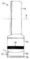
図1は、ファン組立体10の正面図である。ファン組立体10は、好ましくは、スタンド12と、スタンド12に取り付けられると共にこれによって支持されたノズル14とを有する羽根なしファン組立体の形態をしている。スタンド12は、実質的に円筒形の外側ケーシング16を有し、この外側ケーシングは、外側ケーシング16に設けられている孔の形態をした複数個の空気入口18を有し、一次空気流は、外部環境からこれら空気入口を通ってスタンド12内に引き込まれる。スタンド12は、ファン組立体10の動作を制御する複数個のユーザにより操作可能なボタン20及びユーザにより操作可能なダイヤル22を更に有している。この例では、スタンド12の高さは、200〜300mmであり、外側ケーシング16の外径は、100〜200mmである。 FIG. 1 is a front view of the
更に図2を参照すると、ノズル14は、環状の形をしており、このノズルは、中央開口部24を画定又は構成している。ノズル14の高さは、200〜400mmである。ノズル14は、ファン組立体10の後部寄りに設けられていて、空気をファン組立体10から開口部24を通って放出する口(マウス)26を有している。口26は、開口部24周りに少なくとも部分的に延びている。ノズル14の内周部は、口26に隣接して設けられたコアンダ面28を有し、口26は、ファン10から放出された空気をコアンダ面28上でこれに沿って差し向け、ノズル14の内周部は更に、コアンダ面28の下流側に位置するディフューザ面30及びディフューザ面30の上流側に位置する案内面32を有している。ディフューザ面30は、ファン組立体10から放出される空気の流れを助けるために開口部24の中心軸線Xから遠ざかってテーパするよう配置されている。ディフューザ面30と開口部24の中心軸線Xとのなす角度は、5°〜25°であり、この例では約15°である。案内面32は、ファン組立体10からの冷却用空気流の効率的な送り出しを一段と助けるようディフューザ面30に対して角度をなして配置されている。案内面32は、好ましくは、実質的に平らで且つ実質的に滑らかなフェースを口26から放出された空気流に提供するよう開口部24の中心軸線Xに実質的に平行に配置されている。見栄えの良いテーパ付き表面34が、案内面32から見て下流側に設けられており、開口部24の中心軸線Xに実質的に垂直に位置する先端面36で終端している。テーパ面34と開口部24の中心軸線Xとのなす角度は、好ましくは約45°である。開口部24の中心軸線Xに沿って延びる方向におけるノズル24の全深さは、100〜150mmであり、この例では、約110mmである。 Still referring to FIG. 2, the
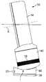
図3は、ファン組立体10の断面図である。スタンド12は、下側ベース部材38及び下側ベース部材38に取り付けられた上側ベース部材40で形成されたベースと、ベースに取り付けられた本体42とで形成されている。かくして、図1及び図5に示されているように、本体42とベースとの間にはインターフェイスIが形成されている。インターフェイスIは、湾曲した、好ましくは起伏のある外周部を有する。かくして、少なくともインターフェイスに隣接して位置するベース及び本体42の外面は、実質的に同一のプロフィールを有し、この実施形態では、円形のプロフィールを有する。 FIG. 3 is a cross-sectional view of the
下側ベース部材38は、実質的に平らな底面43を有している。上側ベース部材40は、図1及び図2に示されたユーザにより操作可能なボタン20の押し下げ及び/又はユーザにより操作可能なダイヤル22の操作に応答してファン組立体10の動作を制御するコントローラ44を収容している。上側ベース部材40は、上側ベース部材40及び本体42を下側ベース部材38に対して揺動させる揺動機構体46を更に収容するのが良い。本体42の各揺動サイクルの範囲は、好ましくは60°〜120°であり、この例では、約90°である。この例では、揺動機構体46は、毎分約3〜5回の揺動サイクルを実施するよう構成されている。電源ケーブル48が、電力をファン組立体10に供給するために下側ベース部材38に形成された孔を貫通している。 The
スタンド12の本体42は、ノズル14が例えばスナップ嵌め連結方式で連結された開放上端部を有する。本体42は、スタンド12の空気入口18を構成するよう孔のアレイが形成された円筒形グリル50を有している。 The
本体42は、グリル50の孔を通って主要空気流量をスタンド12中に引き込むための羽根車52を収容している。好ましくは、羽根車52は、混流型羽根車の形態をしている。羽根車52は、モータ56から外方に延びる回転シャフト54に連結されている。この例では、モータ56は、ダイヤル22のユーザによる操作に応答して速度がコントローラ44によって変化するDCブラシレスモータである。モータ56の最大速度は、好ましくは、5,000〜10,000rpmである。モータ56は、モータバケット内に収容され、このモータバケットは、上側部分58を下側部分60に連結したものである。 The
モータバケットの上側部分58及び下側部分60のうちの一方は、螺旋羽根を備えた静止円板の形態をしていて、羽根車52から見て下流側に配置されたディフューザ62を有する。 One of the upper part 58 and the
モータバケットは、羽根車ハウジング64内に配置されると共にこれに取り付けられている。羽根車ハウジング64は、スタンド12の本体42内に配置されている複数個の角度間隔を置いた支持体66、この例では3つの支持体に取り付けられている。全体として切頭円錐形のシュラウド68が、羽根車ハウジング64内に設けられている。シュラウド68は、羽根車52の外縁部がシュラウド68の内面に密接するが、これには接触しないよう形作られている。実質的に環状の入口部材70が、一次空気流を羽根車ハウジング64内に案内するために羽根車ハウジング64の底部に連結されている。好ましくは、スタンド12は、スタンド12から出る騒音を減少させる消音化フォームを更に有する。この例では、スタンド12の本体42は、本体42のベース寄りに配置された円板形フォーム部材72及びモータバケット内に配置された実質的に環状のフォーム部材74を有している。 The motor bucket is disposed within and attached to the
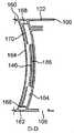
図4は、ノズル14の断面図である。ノズル14は、環状の外側ケーシング区分80を有し、この外側ケーシング区分は、環状の内側ケーシング区分82に連結された状態でこの周りに延びている。これら区分の各々は、複数個の互いに連結された部品で形成されても良いが、この実施形態では、外側ケーシング区分80及び内側ケーシング区分82の各々は、それぞれ単一の成形部品で作られている。内側ケーシング区分82は、ノズル14の中央開口部24を構成し、この内側ケーシング区分は、コアンダ面28、ディフューザ面30、案内面32及びテーパ面34を備えるよう形作られた外周面84を備えている。 FIG. 4 is a cross-sectional view of the
外側ケーシング区分80と内側ケーシング区分82は一緒になって、ノズル14の環状内部通路86を構成している。かくして、内部通路86は、開口部24周りに延びている。内部通路86は、外側ケーシング区分80の内周面88及び内側ケーシング区分82の内周面90によって画定又は構成されている。外側ケーシング区分80は、例えばスナップ嵌め連結方式によってスタンド12の本体42の開放上端部に連結されると共にこれを覆っているベース92を有する。外側ケーシング区分80のベース92は、一次空気流がスタンドの12の本体42の開放上端部からノズル14の内部通路86に流入するようかかる一次空気流を通す孔を有している。 Together, the
ノズル14の口26は、ファン組立体10の後部寄りに配置されている。口26は、外側ケーシング区分80の内周面88及び内側ケーシング区分82の外周面84のそれぞれの互いにオーバーラップした又は向かい合った部分94,96によって画定されている。この例では、口26は、実質的に環状であり、図4に示されているように、この口は、ノズル14を直径方向に通る線に沿って見て実質的にU字形の断面を有する。この例では、外側ケーシング区分80の内周面88及び内側ケーシング区分82の外周面84の互いにオーバーラップした部分94,96は、口26が一次空気流をコアンダ面28上でこれに沿って差し向けるよう構成された出口98に向かってテーパするよう形作られている。出口98は、好ましくは0.5〜5mmの比較的一定の幅を有する環状スロットの形態をしている。この例では、出口98の幅は、約1.0mmである。外側ケーシング区分80の内周面88及び内側ケーシング区分82の外周面84の互いにオーバーラップした部分94,96を互いに押し離して出口98の幅を所望のレベルに維持するためのスペーサが口26の周りに間隔を置いて設けられるのが良い。これらスペーサは、外側ケーシング区分80の内周面88か内側ケーシング区分82の外周面84かのいずれかと一体であるのが良い。 The
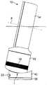
次に、図5(a)、図5(b)及び図5(c)を参照すると、本体42は、スタンド12のベースに対して、図5(b)に示されている第1の完全傾動位置と図5(c)に示されている第2の完全傾動位置との間で動くことができる。この軸線Xは、好ましくは、本体を図5(a)に示されている非傾動位置からこれら2つの完全傾動位置のうちの一方に動かすと、約10°の角度だけ傾けられる。本体42及び上側ベース部材40の外面は、本体42が非傾動位置にあるとき、本体42及びスタンド12のこれら外面の隣接部分が互いに実質的に面一をなすよう形作られている。 Next, referring to FIGS. 5 (a), 5 (b) and 5 (c), the
図6を参照すると、上側ベース部材40は、下側ベース部材38に取り付けられた環状下面100、実質的に円筒形の側壁102及び湾曲した上面104を有している。側壁102は、複数個の孔106を有している。ユーザにより操作可能なダイヤル22は、孔106のうちの1つから突き出ており、これに対し、ユーザにより操作可能なボタン20は、他の孔106を介して接近可能である。上側ベース部材40の湾曲した上面104は、形状が凹状であり、全体として鞍形であると形容できる。モータ56から延びる電気ケーブル110(図3に示されている)を受け入れる孔108が、上側ベース部材40の上面104に形成されている。 Referring to FIG. 6, the
上側ベース部材40は、本体42を上側ベース部材40上に支持する4つの支持部材120を更に有している。支持部材120は、上側ベース部材40の上面104から上方に突き出ており、これら支持部材は、これらが互いに実質的に等距離を置くと共に上面104の中心から実質的に等距離を置いて位置するよう配置されている。第1の対をなす支持部材120は、図9(a)にB‐B線に沿って配置され、第2の対をなす支持部材120は、第1の対をなす支持部材120と平行である。さらに図9(b)及び図9(c)を参照すると、各支持部材120は、円筒形外壁122、開放上端部124及び閉鎖下端部126を有している。支持部材120の外壁122は、ボールベアリング(球状支承体)の形態の転動要素128を包囲している。転動要素128は、好ましくは、円筒形外壁122の半径よりも僅かに小さい半径を有し、従って、転動要素128は、支持部材120によって保持された状態でこの中で動くことができるようになっている。転動要素128は、支持部材120の閉鎖下端部126と転動要素128との間に設けられた弾性要素130により上側ベース部材40の上面104から押し離されており、その結果、転動要素128の一部が支持部材120の開放上端部124を越えて突き出るようになっている。この実施形態では、弾性部材130は、コイルばねの形態をしている。 The
図6に戻ってこれを参照すると、上側ベース部材40は、本体42を上側ベース部材40上に保持する複数本のレールを更に有している。レールは又、上側ベース部材40に対する本体42の運動を案内するのに役立ち、従って、本体42を傾動位置から動かし又は傾動位置に動かしているときに、上側ベース部材40に対する本体42の捩り又は回転が実質的に生じないようになっている。レールの各々は、軸線Xに実質的に平行な方向に延びている。例えば、レールのうちの1本は、図10(a)に示されたD‐D線に沿って位置している。この実施形態では、複数本のレールは、1対の比較的短い外側レール142相互間に位置した1対の比較的長い内側レール140を有している。さらに図9(b)及び図10(b)を参照すると、内側レール140の各々は、逆L字形の形態の断面を有し、各内側レールは、それぞれの1対の支持部材120相互間に延び、上側ベース部材40の上面104に連結された状態でこれから直立した壁144を有している。内側レール140の各々は、壁144の長さに沿って延びると共に壁144の頂部から隣接の外側案内レール142に向かって直角に突き出た湾曲フランジ146を更に有している。外側レール142の各々も又、逆L字形の形態の断面を有し、各外側レールは、上側ベース部材40の上面に連結された状態でこれから直立した壁148及び壁148の長さに沿って延びると共に壁148の頂部から直角に隣接の内側案内レール140から突き出た湾曲フランジ150を有している。 Referring back to FIG. 6, the
次に図7及び図8を参照すると、本体42は、実質的に円筒形の側壁160、環状の下端部162及び凹部を構成するよう本体42の下端部162から間隔を置いて位置した湾曲ベース164を有している。グリル50は、好ましくは、側壁160と一体である。本体42の側壁160は、上側ベース部材40の側壁102と実質的に同一の外径を有している。ベース164は、形状が凸状であり、一般に逆鞍形を有するものとして形容可能である。ケーブル110が本体42のベース164から延びることができるようにする孔166がベース164に形成されている。2対の停止部材168が、ベース164の周囲から上方に延びている(図8に示されている)。停止部材168の各対は、軸線Xに実質的に平行な方向に延びる線に沿って位置している。複数の対をなす停止部材168のうちの1対の停止部材は、図10(a)に示されたD‐D線に沿って位置している。 Referring now to FIGS. 7 and 8, the
凸状チルトプレート又は傾動板170が、本体42のベース164に連結されている。傾動板170は、本体42の凹部内に配置されており、この傾動板は、本体42のベース164と実質的に同一の曲率を有している。停止部材168の各々は、傾動板170の周囲に沿って設けられた複数個の孔172の各々からそれぞれ突き出ている。傾動板170は、上側ベース部材40の転動要素128に係合する1対の凸状レース174を構成するよう形作られている。各レース174は、軸線Xに実質的に平行な方向に延びており、各レースは、図9(c)に示されているように、対応のそれぞれ1対の支持部材120の転動要素128を受け入れるよう配置されている。 A convex tilt plate or tilting
傾動板170は、複数個のランナを更に有し、これらランナの各々は、上側ベース部材40のそれぞれ対応のレールの下に少なくとも部分的に配置され、かくして、そのレールと協働して本体42を上側ベース部材40上に保持すると共に上側ベース部材40に対する本体42の運動を案内するよう構成されている。かくして、ランナの各々は、軸線Xに実質的に平行な方向に延びている。例えば、ランナのうちの1つは、図10(a)に示されたD‐D線に沿って位置している。この実施形態では、複数個のランナは、1対の比較的短い外側ランナ182相互間に位置した1対の比較的長い内側ランナ180を含む。さらに図9(b)及び図10(b)を参照すると、内側ランナ180の各々は、逆L字形の形態の断面を有し、各内側ランナは、実質的に垂直の壁184及び壁184の頂部の一部から直角に且つ内方に突き出た湾曲フランジ186を有している。各内側ランナ180の湾曲フランジ186の曲率は、各内側レール140の湾曲フランジ146の曲率と実質的に同一である。外側ランナ182の各々も又、逆L字形の形態の断面を有し、各外側ランナは、実質的に垂直な壁188及び湾曲フランジ190を有し、この湾曲フランジは、壁188の長さに沿って延びると共に壁188の頂部から直角に且つ内方に突き出ている。この場合も又、各外側ランナ182の湾曲フランジ190の曲率は、各外側レール142の湾曲フランジ150の曲率と実質的に同一である。傾動板170は、ケーブル110を受け入れる孔192を更に有している。 The
本体42を上側ベース部材40に連結するために、傾動板170を図7及び図8に示された向きから逆さまにし、傾動板170のレース174を上側ベース部材40の支持部材120の真後ろにこれと一線をなして配置する。本体42の孔166を通って延びている電気ケーブル110を傾動板170及び上側ベース部材40のそれぞれの孔108,192に通し、次に図3に示されているようにコントローラ44に接続するのが良い。次に、傾動板170を上側ベース部材40上でこれに沿って滑らせて転動要素128が図9(b)及び図9(c)に示されているようにレース174に係合するようにし、各外側ランナ182の湾曲フランジ190が図9(b)及び図10(b)に示されているようにそれぞれの外側レール142の湾曲フランジ150の下に配置し、各内側ランナ180の湾曲フランジ186を図9(b)、図10(b)及び図10(c)に示されているようにそれぞれの内側レール140の湾曲フランジ146の下に配置するようにする。 In order to connect the
傾動板170を上側ベース部材40上の中央に位置決めした状態で、本体42を傾動板170上に下降させ、停止部材168が傾動板170の孔172内に配置されると共に傾動板170が本体42の凹部内に収容されるようにする。次に、上側ベース部材40及び本体42を逆さまにし、ベース部材40を軸線Xの方向に沿って変位させて傾動板170に設けられている第1の複数個の孔194aが現われるようにする。これら孔194aの各々を本体42のベース164に設けられている管状突出部196aに位置合わせする。セルフタッピンねじを孔194aの各々にねじ込んでこれが下に位置する突出部196aに入るようにし、それにより傾動板170を本体42に部分的に連結する。次に、上側ベース部材40を逆方向に変位させて傾動板170に設けられている第2の複数個の孔194bが現われるようにする。これら孔194bの各々も又、本体42のベース164に設けられている管状突出部196bに位置合わせする。セルフタッピンねじを孔194bの各々にねじ込んでこれが下に位置する突出部196に入り、それにより本体42に対する傾動板170の連結を完了させる。 With the
本体42を上側ベース部材40に取り付け、下側ベース部材38の底面43を支持面上に位置決めすると、本体42は、支持部材120の転動要素128によって支持される。支持部材120の弾性要素130は、本体42を傾動させたときに、上側ベース部材40の上面の擦りを阻止するのに十分な距離だけ転動要素128を支持部材120の閉鎖下端部126から押し離す。例えば、図9(b)、図9(c)、図10(b)及び図10(c)の各々に示されているように、本体42の下端部162は、本体42を傾動させたときに、上側ベース部材40の上面104との接触が阻止されるようかかる上面から押し離される。さらに、弾性要素130の作用により、ランナの湾曲フランジ186,190の凹状上面がレールの湾曲フランジ146,150の凸状下面に押し付けられる。 When the
本体42を上側ベース部材40に対して傾動させるため、ユーザは、本体42を軸線Xに平行な方向に滑らせて本体42を図5(b)及び図5(c)に示された完全傾動位置のうちの一方に向かって動かし、それにより転動要素128がレース174に沿って動くようにする。本体42がいったん所望の位置になると、ユーザは、本体42を解除し、この本体は、ランナの湾曲フランジ186,190の凹状上面と重力の作用で図5(a)に示された非傾動位置に向かう本体42の運動に抵抗するよう作用するレールの湾曲フランジ146,150の凸状下面との間の接触により生じた摩擦力によって所望の位置に保持されている。本体42の完全傾動位置は、各対の停止部材168のうちの1つと対応の内側レール140の相互当接によって定められる。 In order to tilt the
ファン組立体10を作動させるため、ユーザは、スタンド12のボタン20のうちの適当な1つを押し、これに応答して、コントローラ44は、モータ56を作動させて羽根車52を回す。羽根車52の回転により、一次空気流が空気入口18を通ってスタンド12内に引き込まれる。一次空気流は、モータの速度に応じて、毎秒20〜30リットルであるのが良い。一次空気流は、羽根車ハウジング64及び本体42の開放上端部を順次通ってノズル14の内部通路86に入る。ノズル14内において、一次空気流は、ノズル14の中央開口部24周りに互いに逆方向に進む2つの部分空気流に分割される。部分空気流は、内部通路86を通過する際、空気は、ノズル14の口26に流入する。口26内への空気流は、好ましくは、ノズル14の開口部24周りにおいて実質的に均等である。口26の各区分内において、部分空気流の一部分の流れ方向が実質的に逆になる。部分空気流の一部分は、口26のテーパ付き区分により絞られ、出口98を通って放出される。 To activate the
口26から放出された一次空気流は、ノズル14のコアンダ面28上でこれに沿って差し向けられ、それにより外部環境からの、特に口26の出口98周りの領域及びノズル14の後部周りからの空気の同伴によって二次空気流が生じる。この二次空気流は、ノズル14の中央開口部24を通り、ここで、二次空気流は、一次空気流と合流し、それによりノズル14から前方に放出される全空気流又は風が生じる。モータ56の速度に応じて、ファン組立体10から前方に放出される空気の流れの質量流量は、毎秒最大400リットル、好ましくは毎秒最大600リットルになる場合があり、送風の最大速度は、2.5〜4m/sになる場合がある。 The primary air flow emitted from the
ノズル14の口26に沿う一次空気流の均等な分布により、空気流は、ディフューザ面30上でこれに沿って一様に流れるようになる。ディフューザ面30により、空気流が膨張の制御された領域を通って動くようになるので空気流の平均速度が減少する。開口部24の中心軸線Xに対するディフューザ面30の比較的浅い角度により、空気流の膨張は、徐々に起こることができる。もしそうでなければ、強烈な又は迅速な広がりにより空気流は、乱れて膨張領域中に渦が生じる。かかる渦により、空気流中に生じる乱流及び関連の騒音が増大する場合があり、このことは、特に家庭用製品、例えばファンでは望ましくない場合がある。ディフューザ面30を越えて前方に放出された空気流は、引き続き広がる傾向がある。開口部30の中心軸線Xに実質的に平行に延びる案内面32が設けられているので、空気流は一段と収斂又は集中する。その結果、空気流は、効率的にノズル14から出て行くことができ、それによりファン組立体10から数メートルの距離を置いたところで空気流を迅速に受けることができる。 Due to the uniform distribution of the primary air flow along the
本発明は、上述の詳細な説明には限定されない。当業者には変形例が明らかであろう。 The present invention is not limited to the above detailed description. Variations will be apparent to those skilled in the art.
例えば、スタンド12は、ファン組立体以外の種々の電気器具に使用できる。ベースに対する本体42の運動を電動化し、ユーザがボタン20のうちの1つを押すことによって作動されても良い。 For example, the
本発明は、以下のような態様であってもよい。
(1)送風を生じさせるファン組立体であって、スタンドに取り付けられた空気出口を有し、前記スタンドは、ベースと、前記ベースに対して非傾動位置から傾動位置に傾動可能な本体とを有し、前記ベース及び前記本体の各々は、外面を有し、前記外面は、前記本体が前記非傾動位置にあるとき、前記外面の隣り合う部分が互いに実質的に面一をなすよう形作られている、ファン組立体。
(2)前記本体は、前記ベースに対して前記非傾動位置と前記傾動位置との間で摺動可能である。
(3)前記スタンドは、前記ベースと前記本体との間に位置するインターフェイスを有し、前記インターフェイスに隣接して位置する前記ベース及び前記本体の前記外面は、実質的に同一のプロフィールを有する。
(4)前記ベース及び前記本体の前記外面は、実質的に同一のプロフィールを有する。
(5)前記空気出口は、前記スタンドに取り付けられたノズルから成り、前記ノズルは、前記空気流を放出する口を有し、前記ノズルは、前記ノズルの外部からの空気を前記口から放出された前記空気流によって引き込むよう通す開口部の周りに延びている。
(6)前記ノズルは、前記口に隣接して位置するコアンダ面を有し、前記口は、前記口から放出された前記空気流を前記コアンダ面上でこれに沿って差し向けるよう配置されている。
(7)前記ベース及び前記本体の向かい合った表面は、同じ形をなして湾曲している。
(8)ファン組立体用のスタンドであって、ベースと、前記ベースに対して傾動可能な本体とを有し、前記ベース及び前記本体は各々、外面を有し、前記外面は、前記本体が非傾動位置にあるとき、前記外面の隣り合う部分が互いに実質的に面一をなすよう形作られている、スタンド。The following aspects may be sufficient as this invention.
(1) A fan assembly for generating air flow, having an air outlet attached to a stand, wherein the stand includes a base and a main body tiltable from a non-tilting position to a tilting position with respect to the base. Each of the base and the main body has an outer surface, and the outer surface is shaped such that adjacent portions of the outer surface are substantially flush with each other when the main body is in the non-tilting position. The fan assembly.
(2) The main body is slidable between the non-tilting position and the tilting position with respect to the base.
(3) The stand has an interface located between the base and the main body, and the outer surface of the base and the main body located adjacent to the interface have substantially the same profile.
(4) The base and the outer surface of the main body have substantially the same profile.
(5) The air outlet is composed of a nozzle attached to the stand, and the nozzle has a port for discharging the air flow, and the nozzle is configured to discharge air from outside the nozzle from the port. It extends around an opening through which it is drawn by the air flow.
(6) The nozzle has a Coanda surface located adjacent to the mouth, and the mouth is arranged to direct the air flow discharged from the mouth along the Coanda surface. Yes.
(7) The opposing surfaces of the base and the main body are curved in the same shape.
(8) A stand for a fan assembly, comprising a base and a main body tiltable with respect to the base, wherein the base and the main body each have an outer surface, and the outer surface includes the main body A stand configured such that adjacent portions of the outer surface are substantially flush with each other when in the non-tilting position.
10 ファン組立体
12 スタンド
14 空気出口又はノズル
24 開口部
26 口又はマウス
28 コアンダ面
30 ディフューザ面
32 案内面
38,40 スタンドベース
42 スタンド本体
46 揺動機構体
52 羽根車
56 モータ
86 内部通路
I インターフェイスDESCRIPTION OF
Claims (30)
Translated fromJapaneseApplications Claiming Priority (2)
| Application Number | Priority Date | Filing Date | Title |
|---|---|---|---|
| GB0903679.9 | 2009-03-04 | ||
| GB0903679AGB2468322B (en) | 2009-03-04 | 2009-03-04 | Tilting fan stand |
Related Parent Applications (1)
| Application Number | Title | Priority Date | Filing Date |
|---|---|---|---|
| JP2010065067ADivisionJP4861492B2 (en) | 2009-03-04 | 2010-03-02 | Fan assembly |
Related Child Applications (1)
| Application Number | Title | Priority Date | Filing Date |
|---|---|---|---|
| JP2011277170ADivisionJP4961507B2 (en) | 2009-03-04 | 2011-12-19 | Fan assembly |
Publications (2)
| Publication Number | Publication Date |
|---|---|
| JP2011252501A JP2011252501A (en) | 2011-12-15 |
| JP4892641B2true JP4892641B2 (en) | 2012-03-07 |
Family
ID=40580576
Family Applications (5)
| Application Number | Title | Priority Date | Filing Date |
|---|---|---|---|
| JP2010065067AExpired - Fee RelatedJP4861492B2 (en) | 2009-03-04 | 2010-03-02 | Fan assembly |
| JP2011203122AExpired - Fee RelatedJP4892641B2 (en) | 2009-03-04 | 2011-09-16 | Fan assembly |
| JP2011277170AActiveJP4961507B2 (en) | 2009-03-04 | 2011-12-19 | Fan assembly |
| JP2012070007AExpired - Fee RelatedJP5023246B2 (en) | 2009-03-04 | 2012-03-26 | Fan assembly |
| JP2012136900AExpired - Fee RelatedJP5118778B2 (en) | 2009-03-04 | 2012-06-18 | Fan assembly |
Family Applications Before (1)
| Application Number | Title | Priority Date | Filing Date |
|---|---|---|---|
| JP2010065067AExpired - Fee RelatedJP4861492B2 (en) | 2009-03-04 | 2010-03-02 | Fan assembly |
Family Applications After (3)
| Application Number | Title | Priority Date | Filing Date |
|---|---|---|---|
| JP2011277170AActiveJP4961507B2 (en) | 2009-03-04 | 2011-12-19 | Fan assembly |
| JP2012070007AExpired - Fee RelatedJP5023246B2 (en) | 2009-03-04 | 2012-03-26 | Fan assembly |
| JP2012136900AExpired - Fee RelatedJP5118778B2 (en) | 2009-03-04 | 2012-06-18 | Fan assembly |
Country Status (19)
| Country | Link |
|---|---|
| US (3) | US9513028B2 (en) |
| EP (4) | EP2404119B1 (en) |
| JP (5) | JP4861492B2 (en) |
| KR (5) | KR101278525B1 (en) |
| CN (4) | CN201917047U (en) |
| AU (4) | AU2010219486B2 (en) |
| BR (1) | BRPI1005520A2 (en) |
| CA (4) | CA2832668C (en) |
| DK (4) | DK2404119T3 (en) |
| ES (4) | ES2527016T3 (en) |
| GB (3) | GB2468322B (en) |
| IL (1) | IL214152A (en) |
| MY (2) | MY144197A (en) |
| NZ (1) | NZ593319A (en) |
| PL (1) | PL2404119T3 (en) |
| RU (3) | RU2489652C2 (en) |
| SG (2) | SG172637A1 (en) |
| WO (1) | WO2010100451A1 (en) |
| ZA (1) | ZA201107218B (en) |
Families Citing this family (125)
| Publication number | Priority date | Publication date | Assignee | Title |
|---|---|---|---|---|
| GB0814835D0 (en) | 2007-09-04 | 2008-09-17 | Dyson Technology Ltd | A Fan |
| GB2463698B (en) | 2008-09-23 | 2010-12-01 | Dyson Technology Ltd | A fan |
| GB2464736A (en) | 2008-10-25 | 2010-04-28 | Dyson Technology Ltd | Fan with a filter |
| GB2466058B (en)* | 2008-12-11 | 2010-12-22 | Dyson Technology Ltd | Fan nozzle with spacers |
| GB2468312A (en) | 2009-03-04 | 2010-09-08 | Dyson Technology Ltd | Fan assembly |
| GB2468322B (en) | 2009-03-04 | 2011-03-16 | Dyson Technology Ltd | Tilting fan stand |
| GB0903682D0 (en) | 2009-03-04 | 2009-04-15 | Dyson Technology Ltd | A fan |
| GB2468320C (en) | 2009-03-04 | 2011-06-01 | Dyson Technology Ltd | Tilting fan |
| CN202056982U (en) | 2009-03-04 | 2011-11-30 | 戴森技术有限公司 | Humidifying device |
| GB2468326A (en) | 2009-03-04 | 2010-09-08 | Dyson Technology Ltd | Telescopic pedestal fan |
| GB2468323A (en) | 2009-03-04 | 2010-09-08 | Dyson Technology Ltd | Fan assembly |
| PL2276933T3 (en) | 2009-03-04 | 2011-10-31 | Dyson Technology Ltd | A fan |
| GB2468317A (en) | 2009-03-04 | 2010-09-08 | Dyson Technology Ltd | Height adjustable and oscillating fan |
| GB2468329A (en) | 2009-03-04 | 2010-09-08 | Dyson Technology Ltd | Fan assembly |
| GB2468331B (en) | 2009-03-04 | 2011-02-16 | Dyson Technology Ltd | A fan |
| NZ593318A (en) | 2009-03-04 | 2012-11-30 | Dyson Technology Ltd | An annular fan assembly with a silencing member |
| GB2468325A (en)* | 2009-03-04 | 2010-09-08 | Dyson Technology Ltd | Height adjustable fan with nozzle |
| GB2468315A (en) | 2009-03-04 | 2010-09-08 | Dyson Technology Ltd | Tilting fan |
| KR101395177B1 (en) | 2009-03-04 | 2014-05-15 | 다이슨 테크놀러지 리미티드 | A fan |
| GB0919473D0 (en) | 2009-11-06 | 2009-12-23 | Dyson Technology Ltd | A fan |
| GB2478927B (en) | 2010-03-23 | 2016-09-14 | Dyson Technology Ltd | Portable fan with filter unit |
| GB2478925A (en) | 2010-03-23 | 2011-09-28 | Dyson Technology Ltd | External filter for a fan |
| SG186071A1 (en) | 2010-05-27 | 2013-01-30 | Dyson Technology Ltd | Device for blowing air by means of narrow slit nozzle assembly |
| GB2482548A (en) | 2010-08-06 | 2012-02-08 | Dyson Technology Ltd | A fan assembly with a heater |
| GB2482549A (en) | 2010-08-06 | 2012-02-08 | Dyson Technology Ltd | A fan assembly with a heater |
| GB2482547A (en) | 2010-08-06 | 2012-02-08 | Dyson Technology Ltd | A fan assembly with a heater |
| GB2483448B (en) | 2010-09-07 | 2015-12-02 | Dyson Technology Ltd | A fan |
| JP5588565B2 (en) | 2010-10-13 | 2014-09-10 | ダイソン テクノロジー リミテッド | Blower assembly |
| GB2484670B (en) | 2010-10-18 | 2018-04-25 | Dyson Technology Ltd | A fan assembly |
| EP2630373B1 (en) | 2010-10-18 | 2016-12-28 | Dyson Technology Limited | A fan assembly |
| JP5548581B2 (en)* | 2010-10-22 | 2014-07-16 | パナソニック株式会社 | Mist generator and beauty device provided with the same |
| JP5778293B2 (en) | 2010-11-02 | 2015-09-16 | ダイソン テクノロジー リミテッド | Blower assembly |
| GB2486019B (en) | 2010-12-02 | 2013-02-20 | Dyson Technology Ltd | A fan |
| GB2486890B (en)* | 2010-12-23 | 2017-09-06 | Dyson Technology Ltd | A fan |
| CN102777430A (en)* | 2011-05-12 | 2012-11-14 | 任文华 | Fan |
| CN102200144A (en)* | 2011-06-23 | 2011-09-28 | 周云飞 | Bladeless fan |
| CN102322427B (en)* | 2011-06-25 | 2013-02-13 | 应辉 | Fan assembly |
| BR112014001474A2 (en) | 2011-07-27 | 2017-02-21 | Dyson Technology Ltd | fan assembly |
| GB2493506B (en) | 2011-07-27 | 2013-09-11 | Dyson Technology Ltd | A fan assembly |
| US8899378B2 (en) | 2011-09-13 | 2014-12-02 | Black & Decker Inc. | Compressor intake muffler and filter |
| AU2012216659B2 (en) | 2011-09-13 | 2016-03-24 | Black & Decker Inc | Air ducting shroud for cooling an air compressor pump and motor |
| GB201119500D0 (en)* | 2011-11-11 | 2011-12-21 | Dyson Technology Ltd | A fan assembly |
| GB2496877B (en) | 2011-11-24 | 2014-05-07 | Dyson Technology Ltd | A fan assembly |
| GB2498547B (en) | 2012-01-19 | 2015-02-18 | Dyson Technology Ltd | A fan |
| GB2499042A (en) | 2012-02-06 | 2013-08-07 | Dyson Technology Ltd | A nozzle for a fan assembly |
| GB2499041A (en) | 2012-02-06 | 2013-08-07 | Dyson Technology Ltd | Bladeless fan including an ionizer |
| GB2499044B (en) | 2012-02-06 | 2014-03-19 | Dyson Technology Ltd | A fan |
| DE102012100974B4 (en)* | 2012-02-07 | 2013-10-10 | Stego-Holding Gmbh | Fan and arrangement having such a fan |
| GB2512192B (en) | 2012-03-06 | 2015-08-05 | Dyson Technology Ltd | A Humidifying Apparatus |
| GB2500012B (en) | 2012-03-06 | 2016-07-06 | Dyson Technology Ltd | A Humidifying Apparatus |
| RU2606194C2 (en) | 2012-03-06 | 2017-01-10 | Дайсон Текнолоджи Лимитед | Fan unit |
| GB2500011B (en) | 2012-03-06 | 2016-07-06 | Dyson Technology Ltd | A Humidifying Apparatus |
| GB2500010B (en) | 2012-03-06 | 2016-08-24 | Dyson Technology Ltd | A humidifying apparatus |
| GB2500017B (en) | 2012-03-06 | 2015-07-29 | Dyson Technology Ltd | A Humidifying Apparatus |
| GB2500903B (en) | 2012-04-04 | 2015-06-24 | Dyson Technology Ltd | Heating apparatus |
| CN102661295B (en)* | 2012-04-10 | 2014-12-31 | 宁波宏钜电器科技有限公司 | Base component of bladeless fan |
| GB2501301B (en) | 2012-04-19 | 2016-02-03 | Dyson Technology Ltd | A fan assembly |
| GB2532557B (en) | 2012-05-16 | 2017-01-11 | Dyson Technology Ltd | A fan comprsing means for suppressing noise |
| EP2850324A2 (en) | 2012-05-16 | 2015-03-25 | Dyson Technology Limited | A fan |
| GB2518935B (en) | 2012-05-16 | 2016-01-27 | Dyson Technology Ltd | A fan |
| GB2503907B (en)* | 2012-07-11 | 2014-05-28 | Dyson Technology Ltd | A fan assembly |
| CN102889239A (en)* | 2012-11-02 | 2013-01-23 | 李起武 | Fan |
| CN102889233A (en)* | 2012-11-02 | 2013-01-23 | 李起武 | Fan |
| AU350181S (en) | 2013-01-18 | 2013-08-15 | Dyson Technology Ltd | Humidifier or fan |
| AU350179S (en) | 2013-01-18 | 2013-08-15 | Dyson Technology Ltd | Humidifier or fan |
| AU350140S (en) | 2013-01-18 | 2013-08-13 | Dyson Technology Ltd | Humidifier or fan |
| BR302013003358S1 (en) | 2013-01-18 | 2014-11-25 | Dyson Technology Ltd | CONFIGURATION APPLIED ON HUMIDIFIER |
| GB2510195B (en) | 2013-01-29 | 2016-04-27 | Dyson Technology Ltd | A fan assembly |
| SG11201505665RA (en) | 2013-01-29 | 2015-08-28 | Dyson Technology Ltd | A fan assembly |
| CA152658S (en) | 2013-03-07 | 2014-05-20 | Dyson Technology Ltd | Fan |
| CA152657S (en) | 2013-03-07 | 2014-05-20 | Dyson Technology Ltd | Fan |
| CA152656S (en) | 2013-03-07 | 2014-05-20 | Dyson Technology Ltd | Fan |
| USD729372S1 (en) | 2013-03-07 | 2015-05-12 | Dyson Technology Limited | Fan |
| CA152655S (en) | 2013-03-07 | 2014-05-20 | Dyson Technology Ltd | Fan |
| BR302013004394S1 (en) | 2013-03-07 | 2014-12-02 | Dyson Technology Ltd | CONFIGURATION APPLIED TO FAN |
| GB2536767B (en)* | 2013-03-11 | 2017-11-15 | Dyson Technology Ltd | A fan assembly nozzle with control port |
| USD730510S1 (en) | 2013-05-14 | 2015-05-26 | Stego-Holding Gmbh | Air vent |
| CN103453637B (en)* | 2013-06-03 | 2015-09-02 | 海尔集团公司 | Air-conditioner air supply device and there is the air-conditioning of this device |
| CN103453636B (en)* | 2013-06-03 | 2015-09-02 | 海尔集团公司 | Air-conditioner air supply device and air-conditioning |
| GB2516058B (en)* | 2013-07-09 | 2016-12-21 | Dyson Technology Ltd | A fan assembly with an oscillation and tilt mechanism |
| CA154722S (en) | 2013-08-01 | 2015-02-16 | Dyson Technology Ltd | Fan |
| CA154723S (en) | 2013-08-01 | 2015-02-16 | Dyson Technology Ltd | Fan |
| TWD172707S (en) | 2013-08-01 | 2015-12-21 | 戴森科技有限公司 | A fan |
| GB2518638B (en) | 2013-09-26 | 2016-10-12 | Dyson Technology Ltd | Humidifying apparatus |
| JP1518058S (en)* | 2014-01-09 | 2015-02-23 | ||
| JP1518059S (en)* | 2014-01-09 | 2015-02-23 | ||
| GB2528709B (en) | 2014-07-29 | 2017-02-08 | Dyson Technology Ltd | Humidifying apparatus |
| GB2528708B (en) | 2014-07-29 | 2016-06-29 | Dyson Technology Ltd | A fan assembly |
| GB2528704A (en) | 2014-07-29 | 2016-02-03 | Dyson Technology Ltd | Humidifying apparatus |
| US9657742B2 (en)* | 2014-09-15 | 2017-05-23 | Speedtech Energy Co., Ltd. | Solar fan |
| CN104895768A (en)* | 2014-12-18 | 2015-09-09 | 任文华 | Fan assembly and nozzle for fan assembly |
| US11111913B2 (en) | 2015-10-07 | 2021-09-07 | Black & Decker Inc. | Oil lubricated compressor |
| CN105351230B (en)* | 2015-12-10 | 2017-11-28 | 南华大学 | Coanda fin ventilation fan |
| DE102015122491A1 (en) | 2015-12-22 | 2017-06-22 | Volkswagen Aktiengesellschaft | Cooling system and motor vehicle |
| EP3458719B1 (en)* | 2016-05-18 | 2020-05-13 | De' Longhi Appliances S.r.l. Con Unico Socio | Fan |
| WO2018175359A1 (en) | 2017-03-20 | 2018-09-27 | Shop Vac Corporation | Axial fan having housing formed by connectable pieces and including air guide ribs and an internal ramp |
| US11384956B2 (en) | 2017-05-22 | 2022-07-12 | Sharkninja Operating Llc | Modular fan assembly with articulating nozzle |
| CN107575407B (en)* | 2017-09-30 | 2023-11-03 | 广东美的环境电器制造有限公司 | Bladeless fan and handpiece for a bladeless fan |
| GB2568938B (en) | 2017-12-01 | 2020-12-30 | Dyson Technology Ltd | A filter assembly |
| GB2568937B (en) | 2017-12-01 | 2020-08-12 | Dyson Technology Ltd | A fan assembly |
| GB2568979A (en)* | 2017-12-01 | 2019-06-05 | Dyson Technology Ltd | A fan assembly |
| GB2568939B (en) | 2017-12-01 | 2020-12-02 | Dyson Technology Ltd | A fan assembly |
| CN108119379B (en)* | 2018-01-16 | 2024-04-23 | 浙江弩牌电器有限公司 | Air supply device |
| GB2571718B (en) | 2018-03-05 | 2020-12-16 | Dyson Technology Ltd | A fan assembly |
| GB2571717B (en) | 2018-03-05 | 2020-12-16 | Dyson Technology Ltd | A fan assembly |
| WO2019191237A1 (en)* | 2018-03-29 | 2019-10-03 | Walmart Apollo, Llc | Aerial vehicle turbine system |
| US11300128B2 (en)* | 2018-05-11 | 2022-04-12 | Hubbell Incorporated | Bladeless ceiling fan |
| GB2575065B (en) | 2018-06-27 | 2021-03-24 | Dyson Technology Ltd | A nozzle for a fan assembly |
| GB2575063B (en) | 2018-06-27 | 2021-06-09 | Dyson Technology Ltd | A nozzle for a fan assembly |
| GB2575064B (en) | 2018-06-27 | 2021-06-09 | Dyson Technology Ltd | A nozzle for a fan assembly |
| GB2575066B (en) | 2018-06-27 | 2020-11-25 | Dyson Technology Ltd | A nozzle for a fan assembly |
| GB2578616B (en) | 2018-11-01 | 2021-02-24 | Dyson Technology Ltd | A nozzle for a fan assembly |
| GB2578617B (en) | 2018-11-01 | 2021-02-24 | Dyson Technology Ltd | A nozzle for a fan assembly |
| GB2578615B (en) | 2018-11-01 | 2021-10-13 | Dyson Technology Ltd | A fan assembly |
| GB201900025D0 (en) | 2019-01-02 | 2019-02-13 | Dyson Technology Ltd | A fan assembly |
| GB2582796B (en) | 2019-04-03 | 2021-11-03 | Dyson Technology Ltd | Control of a fan assembly |
| US11167855B2 (en)* | 2019-04-30 | 2021-11-09 | Rohr, Inc. | Method and apparatus for aircraft anti-icing |
| US11465758B2 (en) | 2019-04-30 | 2022-10-11 | Rohr, Inc. | Method and apparatus for aircraft anti-icing |
| EP4063667B1 (en)* | 2019-11-18 | 2024-08-28 | Ying, Hui | Fan |
| US11378100B2 (en) | 2020-11-30 | 2022-07-05 | E. Mishan & Sons, Inc. | Oscillating portable fan with removable grille |
| GB2608124B (en) | 2021-06-22 | 2023-11-15 | Dyson Technology Ltd | Nozzle for a fan assembly |
| GB2619527A (en) | 2022-06-07 | 2023-12-13 | Jones Food Company Ltd | Vertical farming system |
| US12161949B2 (en)* | 2022-08-05 | 2024-12-10 | Lizhen Lin | Bubble machine with adjustable blowing angle |
| US20240245190A1 (en) | 2023-01-19 | 2024-07-25 | Sharkninja Operating Llc | Identification of hair care appliance attachments |
| US20250213029A1 (en) | 2023-01-19 | 2025-07-03 | Sharkninja Operating Llc | Hair care appliance with powered attachment |
Family Cites Families (431)
| Publication number | Priority date | Publication date | Assignee | Title |
|---|---|---|---|---|
| US751485A (en)* | 1904-02-09 | Chaeles a | ||
| GB601222A (en) | 1944-10-04 | 1948-04-30 | Berkeley & Young Ltd | Improvements in, or relating to, electric fans |
| GB593828A (en) | 1945-06-14 | 1947-10-27 | Dorothy Barker | Improvements in or relating to propeller fans |
| US1357261A (en) | 1918-10-02 | 1920-11-02 | Ladimir H Svoboda | Fan |
| US1767060A (en) | 1928-10-04 | 1930-06-24 | W H Addington | Electric motor-driven desk fan |
| US2014185A (en) | 1930-06-25 | 1935-09-10 | Martin Brothers Electric Compa | Drier |
| GB383498A (en) | 1931-03-03 | 1932-11-17 | Spontan Ab | Improvements in or relating to fans, ventilators, or the like |
| US1896869A (en)* | 1931-07-18 | 1933-02-07 | Master Electric Co | Electric fan |
| US2035733A (en)* | 1935-06-10 | 1936-03-31 | Marathon Electric Mfg | Fan motor mounting |
| US2210458A (en) | 1936-11-16 | 1940-08-06 | Lester S Keilholtz | Method of and apparatus for air conditioning |
| US2115883A (en)* | 1937-04-21 | 1938-05-03 | Sher Samuel | Lamp |
| US2258961A (en) | 1939-07-26 | 1941-10-14 | Prat Daniel Corp | Ejector draft control |
| US2336295A (en) | 1940-09-25 | 1943-12-07 | Reimuller Caryl | Air diverter |
| GB641622A (en) | 1942-05-06 | 1950-08-16 | Fernan Oscar Conill | Improvements in or relating to hair drying |
| US2433795A (en) | 1945-08-18 | 1947-12-30 | Westinghouse Electric Corp | Fan |
| US2476002A (en)* | 1946-01-12 | 1949-07-12 | Edward A Stalker | Rotating wing |
| US2547448A (en)* | 1946-02-20 | 1951-04-03 | Demuth Charles | Hot-air space heater |
| US2473325A (en)* | 1946-09-19 | 1949-06-14 | E A Lab Inc | Combined electric fan and air heating means |
| US2544379A (en)* | 1946-11-15 | 1951-03-06 | Oscar J Davenport | Ventilating apparatus |
| US2488467A (en)* | 1947-09-12 | 1949-11-15 | Lisio Salvatore De | Motor-driven fan |
| GB633273A (en) | 1948-02-12 | 1949-12-12 | Albert Richard Ponting | Improvements in or relating to air circulating apparatus |
| US2510132A (en)* | 1948-05-27 | 1950-06-06 | Morrison Hackley | Oscillating fan |
| GB661747A (en) | 1948-12-18 | 1951-11-28 | British Thomson Houston Co Ltd | Improvements in and relating to oscillating fans |
| US2620127A (en) | 1950-02-28 | 1952-12-02 | Westinghouse Electric Corp | Air translating apparatus |
| US2583374A (en)* | 1950-10-18 | 1952-01-22 | Hydraulic Supply Mfg Company | Exhaust fan |
| FR1033034A (en)* | 1951-02-23 | 1953-07-07 | Articulated stabilizer support for fan with flexible propellers and variable speeds | |
| US2813673A (en) | 1953-07-09 | 1957-11-19 | Gilbert Co A C | Tiltable oscillating fan |
| US2838229A (en)* | 1953-10-30 | 1958-06-10 | Roland J Belanger | Electric fan |
| US2765977A (en) | 1954-10-13 | 1956-10-09 | Morrison Hackley | Electric ventilating fans |
| FR1119439A (en) | 1955-02-18 | 1956-06-20 | Enhancements to portable and wall fans | |
| US2830779A (en)* | 1955-02-21 | 1958-04-15 | Lau Blower Co | Fan stand |
| NL110393C (en)* | 1955-11-29 | 1965-01-15 | Bertin & Cie | |
| CH346643A (en) | 1955-12-06 | 1960-05-31 | K Tateishi Arthur | Electric fan |
| US2808198A (en) | 1956-04-30 | 1957-10-01 | Morrison Hackley | Oscillating fans |
| GB863124A (en) | 1956-09-13 | 1961-03-15 | Sebac Nouvelle Sa | New arrangement for putting gases into movement |
| BE560119A (en) | 1956-09-13 | |||
| US2922570A (en)* | 1957-12-04 | 1960-01-26 | Burris R Allen | Automatic booster fan and ventilating shield |
| US3004403A (en) | 1960-07-21 | 1961-10-17 | Francis L Laporte | Refrigerated space humidification |
| DE1291090B (en) | 1963-01-23 | 1969-03-20 | Schmidt Geb Halm Anneliese | Device for generating an air flow |
| DE1457461A1 (en) | 1963-10-01 | 1969-02-20 | Siemens Elektrogeraete Gmbh | Suitcase-shaped hair dryer |
| FR1387334A (en) | 1963-12-21 | 1965-01-29 | Hair dryer capable of blowing hot and cold air separately | |
| US3204898A (en)* | 1964-02-17 | 1965-09-07 | Product Engineering Company | Adjustable support |
| US3270655A (en) | 1964-03-25 | 1966-09-06 | Howard P Guirl | Air curtain door seal |
| US3518776A (en)* | 1967-06-03 | 1970-07-07 | Bremshey & Co | Blower,particularly for hair-drying,laundry-drying or the like |
| US3444817A (en) | 1967-08-23 | 1969-05-20 | William J Caldwell | Fluid pump |
| US3487555A (en) | 1968-01-15 | 1970-01-06 | Hoover Co | Portable hair dryer |
| US3495343A (en) | 1968-02-20 | 1970-02-17 | Rayette Faberge | Apparatus for applying air and vapor to the face and hair |
| US3503138A (en)* | 1969-05-19 | 1970-03-31 | Oster Mfg Co John | Hair dryer |
| GB1278606A (en) | 1969-09-02 | 1972-06-21 | Oberlind Veb Elektroinstall | Improvements in or relating to transverse flow fans |
| US3645007A (en) | 1970-01-14 | 1972-02-29 | Sunbeam Corp | Hair dryer and facial sauna |
| DK122977B (en)* | 1970-07-10 | 1972-05-01 | Nordisk Ventilator | Axial fan whose impeller has adjustable blades during operation. |
| DE2944027A1 (en) | 1970-07-22 | 1981-05-07 | Erevanskyj politechničeskyj institut imeni Karla Marksa, Erewan | EJECTOR ROOM AIR CONDITIONER OF THE CENTRAL AIR CONDITIONING |
| US3724092A (en)* | 1971-07-12 | 1973-04-03 | Westinghouse Electric Corp | Portable hair dryer |
| GB1403188A (en) | 1971-10-22 | 1975-08-28 | Olin Energy Systems Ltd | Fluid flow inducing apparatus |
| JPS517258Y2 (en) | 1971-11-15 | 1976-02-27 | ||
| US3743186A (en)* | 1972-03-14 | 1973-07-03 | Src Lab | Air gun |
| US3885891A (en)* | 1972-11-30 | 1975-05-27 | Rockwell International Corp | Compound ejector |
| US3795367A (en)* | 1973-04-05 | 1974-03-05 | Src Lab | Fluid device using coanda effect |
| US3872916A (en)* | 1973-04-05 | 1975-03-25 | Int Harvester Co | Fan shroud exit structure |
| JPS49150403U (en) | 1973-04-23 | 1974-12-26 | ||
| US4037991A (en)* | 1973-07-26 | 1977-07-26 | The Plessey Company Limited | Fluid-flow assisting devices |
| US3875745A (en)* | 1973-09-10 | 1975-04-08 | Wagner Minning Equipment Inc | Venturi exhaust cooler |
| GB1434226A (en) | 1973-11-02 | 1976-05-05 | Roberts S A | Pumps |
| US3943329A (en)* | 1974-05-17 | 1976-03-09 | Clairol Incorporated | Hair dryer with safety guard air outlet nozzle |
| CA1055344A (en) | 1974-05-17 | 1979-05-29 | International Harvester Company | Heat transfer system employing a coanda effect producing fan shroud exit |
| US4184541A (en)* | 1974-05-22 | 1980-01-22 | International Harvester Company | Heat exchange apparatus including a toroidal-type radiator |
| US4180130A (en)* | 1974-05-22 | 1979-12-25 | International Harvester Company | Heat exchange apparatus including a toroidal-type radiator |
| GB1501473A (en) | 1974-06-11 | 1978-02-15 | Charbonnages De France | Fans |
| GB1495013A (en)* | 1974-06-25 | 1977-12-14 | British Petroleum Co | Coanda unit |
| GB1593391A (en)* | 1977-01-28 | 1981-07-15 | British Petroleum Co | Flare |
| JPS517258U (en) | 1974-07-01 | 1976-01-20 | ||
| JPS517258A (en)* | 1974-07-11 | 1976-01-21 | Tsudakoma Ind Co Ltd | YOKOITO CHORYUSOCHI |
| DE2451557C2 (en) | 1974-10-30 | 1984-09-06 | Arnold Dipl.-Ing. 8904 Friedberg Scheel | Device for ventilating a occupied zone in a room |
| US4136735A (en)* | 1975-01-24 | 1979-01-30 | International Harvester Company | Heat exchange apparatus including a toroidal-type radiator |
| US4061188A (en)* | 1975-01-24 | 1977-12-06 | International Harvester Company | Fan shroud structure |
| US4173995A (en)* | 1975-02-24 | 1979-11-13 | International Harvester Company | Recirculation barrier for a heat transfer system |
| US4332529A (en)* | 1975-08-11 | 1982-06-01 | Morton Alperin | Jet diffuser ejector |
| US4046492A (en) | 1976-01-21 | 1977-09-06 | Vortec Corporation | Air flow amplifier |
| JPS531015A (en) | 1976-06-25 | 1978-01-07 | Nippon Gakki Seizo Kk | Electronic musical instrument |
| JPS5351608A (en) | 1976-10-20 | 1978-05-11 | Asahi Giken Kk | Fluid conveying tube to be installed under the water surface |
| JPS5531911Y2 (en) | 1976-10-25 | 1980-07-30 | ||
| DK140426B (en) | 1976-11-01 | 1979-08-27 | Arborg O J M | Propulsion nozzle for means of transport in air or water. |
| US4113416A (en) | 1977-02-24 | 1978-09-12 | Ishikawajima-Harima Jukogyo Kabushiki Kaisha | Rotary burner |
| JPS56148100A (en) | 1980-04-21 | 1981-11-17 | Tokyo Shibaura Electric Co | Pipe through device of nuclear reactor container |
| JPS5719995Y2 (en) | 1980-05-13 | 1982-04-27 | ||
| JPS56167897A (en)* | 1980-05-28 | 1981-12-23 | Toshiba Corp | Fan |
| AU7279281A (en) | 1980-07-17 | 1982-01-21 | General Conveyors Ltd. | Variable nozzle for jet pump |
| JPS5771000U (en) | 1980-10-20 | 1982-04-30 | ||
| MX147915A (en) | 1981-01-30 | 1983-01-31 | Philips Mexicana S A De C V | ELECTRIC FAN |
| JPS57157097A (en)* | 1981-03-20 | 1982-09-28 | Sanyo Electric Co Ltd | Fan |
| JPS57157097U (en) | 1981-03-30 | 1982-10-02 | ||
| GB2096234B (en)* | 1981-04-03 | 1985-02-20 | Mouldmaking Design Centre Ltd | Swivel mounting |
| US4568243A (en) | 1981-10-08 | 1986-02-04 | Barry Wright Corporation | Vibration isolating seal for mounting fans and blowers |
| CH662623A5 (en) | 1981-10-08 | 1987-10-15 | Wright Barry Corp | INSTALLATION FRAME FOR A FAN. |
| GB2111125A (en) | 1981-10-13 | 1983-06-29 | Beavair Limited | Apparatus for inducing fluid flow by Coanda effect |
| US4448354A (en)* | 1982-07-23 | 1984-05-15 | The United States Of America As Represented By The Secretary Of The Air Force | Axisymmetric thrust augmenting ejector with discrete primary air slot nozzles |
| US4566243A (en)* | 1982-07-29 | 1986-01-28 | Benchcraft, Inc. | Plank grating assembly |
| US4502837A (en) | 1982-09-30 | 1985-03-05 | General Electric Company | Multi stage centrifugal impeller |
| FR2534983A1 (en) | 1982-10-20 | 1984-04-27 | Chacoux Claude | Jet supersonic compressor |
| US4718870A (en)* | 1983-02-15 | 1988-01-12 | Techmet Corporation | Marine propulsion system |
| US4575033A (en)* | 1983-04-04 | 1986-03-11 | Honeywell Information Systems Inc. | Tilt-swivel base for a CRT display terminal |
| JPS59167984U (en) | 1983-04-27 | 1984-11-10 | 三菱電機株式会社 | Mixed flow duct fan |
| JPH0686898B2 (en) | 1983-05-31 | 1994-11-02 | ヤマハ発動機株式会社 | V-belt type automatic continuously variable transmission for vehicles |
| JPS59193689U (en) | 1983-06-09 | 1984-12-22 | 村田機械株式会社 | Robotic hand for transferring circular or cylindrical objects |
| JPS60105896U (en) | 1983-12-26 | 1985-07-19 | 株式会社日立製作所 | mixed flow fan |
| US4533105A (en)* | 1984-04-27 | 1985-08-06 | Zenith Electronics Corporation | Tiltable display monitor assembly |
| KR900001873B1 (en)* | 1984-06-14 | 1990-03-26 | 산요덴끼 가부시끼가이샤 | Ultrasonic humidifier |
| USD288876S (en)* | 1984-06-15 | 1987-03-24 | International Business Machines Corporation | Adjustable display stand |
| JP2594029B2 (en) | 1984-07-25 | 1997-03-26 | 三洋電機株式会社 | Ultrasonic humidifier |
| US4621782A (en)* | 1984-07-26 | 1986-11-11 | At&T Bell Laboratories | Arrangement for mounting apparatus |
| JPS61116093A (en) | 1984-11-12 | 1986-06-03 | Matsushita Electric Ind Co Ltd | Fan |
| FR2574854B1 (en) | 1984-12-17 | 1988-10-28 | Peugeot Aciers Et Outillage | MOTOR FAN, PARTICULARLY FOR MOTOR VEHICLE, FIXED ON SOLID BODY SUPPORT ARMS |
| JPH0351913Y2 (en) | 1984-12-31 | 1991-11-08 | ||
| US4630475A (en) | 1985-03-20 | 1986-12-23 | Sharp Kabushiki Kaisha | Fiber optic level sensor for humidifier |
| JPS61218824A (en) | 1985-03-25 | 1986-09-29 | Matsushita Electric Ind Co Ltd | stay device |
| JPS61280787A (en) | 1985-05-30 | 1986-12-11 | Sanyo Electric Co Ltd | Fan |
| US4832576A (en) | 1985-05-30 | 1989-05-23 | Sanyo Electric Co., Ltd. | Electric fan |
| JPH0443895Y2 (en) | 1985-07-22 | 1992-10-16 | ||
| SU1320519A1 (en)* | 1985-08-08 | 1987-06-30 | Азербайджанский Научно-Исследовательский Электротехнический Институт | Household fan |
| US4703152A (en)* | 1985-12-11 | 1987-10-27 | Holmes Products Corp. | Tiltable and adjustably oscillatable portable electric heater/fan |
| GB2185533A (en) | 1986-01-08 | 1987-07-22 | Rolls Royce | Ejector pumps |
| GB2185531B (en) | 1986-01-20 | 1989-11-22 | Mitsubishi Electric Corp | Electric fans |
| US4732539A (en)* | 1986-02-14 | 1988-03-22 | Holmes Products Corp. | Oscillating fan |
| JPH0352515Y2 (en) | 1986-02-20 | 1991-11-14 | ||
| JPH0674190B2 (en) | 1986-02-27 | 1994-09-21 | 住友電気工業株式会社 | Aluminum nitride sintered body having metallized surface |
| JPS62223494A (en) | 1986-03-21 | 1987-10-01 | Uingu:Kk | Cold air fan |
| US4850804A (en)* | 1986-07-07 | 1989-07-25 | Tatung Company Of America, Inc. | Portable electric fan having a universally adjustable mounting |
| JPH0759064B2 (en)* | 1986-08-19 | 1995-06-21 | ソニー株式会社 | Tilt stand |
| US4790133A (en) | 1986-08-29 | 1988-12-13 | General Electric Company | High bypass ratio counterrotating turbofan engine |
| DE3644567C2 (en) | 1986-12-27 | 1993-11-18 | Ltg Lufttechnische Gmbh | Process for blowing supply air into a room |
| JPH0781559B2 (en) | 1987-01-20 | 1995-08-30 | 三洋電機株式会社 | Blower |
| CN87202488U (en) | 1987-02-28 | 1988-03-30 | 孟武 | Electric fan generating natural wind |
| JPH0821400B2 (en) | 1987-03-04 | 1996-03-04 | 関西電力株式会社 | Electrolyte circulation type secondary battery |
| JPS63179198U (en) | 1987-05-11 | 1988-11-21 | ||
| JPS63306340A (en) | 1987-06-06 | 1988-12-14 | Koichi Hidaka | Bacteria preventive ultrasonic humidifier incorporating sterilizing lamp lighting circuit |
| JPS6421300U (en) | 1987-07-27 | 1989-02-02 | ||
| JPS6483884A (en) | 1987-09-28 | 1989-03-29 | Matsushita Seiko Kk | Chargeable electric fan |
| JPH0660638B2 (en)* | 1987-10-07 | 1994-08-10 | 松下電器産業株式会社 | Mixed flow impeller |
| JPH01138399A (en) | 1987-11-24 | 1989-05-31 | Sanyo Electric Co Ltd | Blowing fan |
| JPH0633850B2 (en) | 1988-03-02 | 1994-05-02 | 三洋電機株式会社 | Device elevation angle adjustment device |
| JPH01138399U (en) | 1988-03-15 | 1989-09-21 | ||
| JPH0636437Y2 (en) | 1988-04-08 | 1994-09-21 | 耕三 福田 | Air circulation device |
| US4878620A (en) | 1988-05-27 | 1989-11-07 | Tarleton E Russell | Rotary vane nozzle |
| US4978281A (en) | 1988-08-19 | 1990-12-18 | Conger William W Iv | Vibration dampened blower |
| US6293121B1 (en) | 1988-10-13 | 2001-09-25 | Gaudencio A. Labrador | Water-mist blower cooling system and its new applications |
| JPH02146294A (en) | 1988-11-24 | 1990-06-05 | Japan Air Curtain Corp | Air blower |
| FR2640857A1 (en) | 1988-12-27 | 1990-06-29 | Seb Sa | Hairdryer with an air exit flow of modifiable form |
| JPH02218890A (en) | 1989-02-20 | 1990-08-31 | Matsushita Seiko Co Ltd | Oscillating device for fan |
| JPH02248690A (en)* | 1989-03-22 | 1990-10-04 | Hitachi Ltd | Fan |
| US5203521A (en) | 1989-05-12 | 1993-04-20 | Day Terence R | Annular body aircraft |
| JPH033419A (en) | 1989-05-30 | 1991-01-09 | Nec Corp | Phase synchronization circuit |
| JPH0695808B2 (en) | 1989-07-14 | 1994-11-24 | 三星電子株式会社 | Induction motor control circuit and control method |
| GB2236804A (en) | 1989-07-26 | 1991-04-17 | Anthony Reginald Robins | Compound nozzle |
| GB2237323A (en) | 1989-10-06 | 1991-05-01 | Coal Ind | Fan silencer apparatus |
| GB2240268A (en) | 1990-01-29 | 1991-07-31 | Wik Far East Limited | Hair dryer |
| US5061405A (en) | 1990-02-12 | 1991-10-29 | Emerson Electric Co. | Constant humidity evaporative wicking filter humidifier |
| FR2658593B1 (en) | 1990-02-20 | 1992-05-07 | Electricite De France | AIR INLET. |
| GB9005709D0 (en) | 1990-03-14 | 1990-05-09 | S & C Thermofluids Ltd | Coanda flue gas ejectors |
| JP2619548B2 (en) | 1990-03-19 | 1997-06-11 | 株式会社日立製作所 | Blower |
| JPH03127331U (en)* | 1990-04-02 | 1991-12-20 | ||
| JPH0443895A (en) | 1990-06-08 | 1992-02-13 | Matsushita Seiko Co Ltd | Controller of electric fan |
| USD325435S (en)* | 1990-09-24 | 1992-04-14 | Vornado Air Circulation Systems, Inc. | Fan support base |
| JPH0499258U (en)* | 1991-01-14 | 1992-08-27 | ||
| CN2085866U (en) | 1991-03-16 | 1991-10-02 | 郭维涛 | Portable electric fan |
| US5188508A (en)* | 1991-05-09 | 1993-02-23 | Comair Rotron, Inc. | Compact fan and impeller |
| JPH04366330A (en) | 1991-06-12 | 1992-12-18 | Taikisha Ltd | Induction type blowing device |
| JP3146538B2 (en) | 1991-08-08 | 2001-03-19 | 松下電器産業株式会社 | Non-contact height measuring device |
| DE4127134B4 (en) | 1991-08-15 | 2004-07-08 | Papst Licensing Gmbh & Co. Kg | diagonal fan |
| US5168722A (en) | 1991-08-16 | 1992-12-08 | Walton Enterprises Ii, L.P. | Off-road evaporative air cooler |
| JPH05263786A (en) | 1992-07-23 | 1993-10-12 | Sanyo Electric Co Ltd | Electric fan |
| JPH05157093A (en) | 1991-12-03 | 1993-06-22 | Sanyo Electric Co Ltd | Electric fan |
| JPH05164089A (en) | 1991-12-10 | 1993-06-29 | Matsushita Electric Ind Co Ltd | Axial fan motor |
| US5296769A (en)* | 1992-01-24 | 1994-03-22 | Electrolux Corporation | Air guide assembly for an electric motor and methods of making |
| US5762661A (en)* | 1992-01-31 | 1998-06-09 | Kleinberger; Itamar C. | Mist-refining humidification system having a multi-direction, mist migration path |
| CN2111392U (en) | 1992-02-26 | 1992-07-29 | 张正光 | Switch device for electric fan |
| JP3109277B2 (en) | 1992-09-09 | 2000-11-13 | 松下電器産業株式会社 | Clothes dryer |
| JPH06147188A (en) | 1992-11-10 | 1994-05-27 | Hitachi Ltd | Electric fan |
| US5411371A (en)* | 1992-11-23 | 1995-05-02 | Chen; Cheng-Ho | Swiveling electric fan |
| US5310313A (en)* | 1992-11-23 | 1994-05-10 | Chen C H | Swinging type of electric fan |
| JP3064714B2 (en)* | 1992-12-18 | 2000-07-12 | 三菱電機株式会社 | Tilt stand |
| JPH06257591A (en) | 1993-03-08 | 1994-09-13 | Hitachi Ltd | Fan |
| JPH06280800A (en) | 1993-03-29 | 1994-10-04 | Matsushita Seiko Co Ltd | Induced blast device |
| JPH06336113A (en) | 1993-05-28 | 1994-12-06 | Sawafuji Electric Co Ltd | Automotive humidifier |
| US5395087A (en) | 1993-06-01 | 1995-03-07 | Dexter Coffman | Adjustable stand for positive pressure blower |
| US5317815A (en)* | 1993-06-15 | 1994-06-07 | Hwang Shyh Jye | Grille assembly for hair driers |
| JPH0674190A (en) | 1993-07-30 | 1994-03-15 | Sanyo Electric Co Ltd | Fan |
| US5402938A (en)* | 1993-09-17 | 1995-04-04 | Exair Corporation | Fluid amplifier with improved operating range using tapered shim |
| US5425902A (en)* | 1993-11-04 | 1995-06-20 | Tom Miller, Inc. | Method for humidifying air |
| US5518216A (en)* | 1993-11-05 | 1996-05-21 | Acer Peripherals, Inc. | Direction and an angle adjustment apparatus for a video display device |
| GB2285504A (en) | 1993-12-09 | 1995-07-12 | Alfred Slack | Hot air distribution |
| JPH07190443A (en) | 1993-12-24 | 1995-07-28 | Matsushita Seiko Co Ltd | Blower equipment |
| US5407324A (en)* | 1993-12-30 | 1995-04-18 | Compaq Computer Corporation | Side-vented axial fan and associated fabrication methods |
| JP2921384B2 (en) | 1994-03-04 | 1999-07-19 | 株式会社日立製作所 | Mixed flow fan |
| CN1037122C (en)* | 1994-05-07 | 1998-01-21 | 陈正和 | Oscillating fan |
| DE4418014A1 (en)* | 1994-05-24 | 1995-11-30 | E E T Umwelt Und Gastechnik Gm | Method of conveying and mixing a first fluid with a second fluid under pressure |
| US5645769A (en) | 1994-06-17 | 1997-07-08 | Nippondenso Co., Ltd. | Humidified cool wind system for vehicles |
| JP3614467B2 (en) | 1994-07-06 | 2005-01-26 | 鎌田バイオ・エンジニアリング株式会社 | Jet pump |
| DE19510397A1 (en) | 1995-03-22 | 1996-09-26 | Piller Gmbh | Blower unit for car=wash |
| CA2155482A1 (en) | 1995-03-27 | 1996-09-28 | Honeywell Consumer Products, Inc. | Portable electric fan heater |
| US5518370A (en)* | 1995-04-03 | 1996-05-21 | Duracraft Corporation | Portable electric fan with swivel mount |
| FR2735854B1 (en)* | 1995-06-22 | 1997-08-01 | Valeo Thermique Moteur Sa | DEVICE FOR ELECTRICALLY CONNECTING A MOTOR-FAN FOR A MOTOR VEHICLE HEAT EXCHANGER |
| US5620633A (en) | 1995-08-17 | 1997-04-15 | Circulair, Inc. | Spray misting device for use with a portable-sized fan |
| CN2228996Y (en) | 1995-08-22 | 1996-06-12 | 广东省二轻制冷机公司 | Vane for low-noise centrifugal fan |
| US6126393A (en) | 1995-09-08 | 2000-10-03 | Augustine Medical, Inc. | Low noise air blower unit for inflating blankets |
| JP3843472B2 (en) | 1995-10-04 | 2006-11-08 | 株式会社日立製作所 | Ventilator for vehicles |
| US5720594A (en) | 1995-12-13 | 1998-02-24 | Holmes Products Corp. | Fan oscillating in two axes |
| US5762034A (en)* | 1996-01-16 | 1998-06-09 | Board Of Trustees Operating Michigan State University | Cooling fan shroud |
| JPH09233407A (en)* | 1996-02-21 | 1997-09-05 | Sony Corp | Tilt stand with lock, transferring palette and lock canceling method for tilt stand with lock |
| US5609473A (en) | 1996-03-13 | 1997-03-11 | Litvin; Charles | Pivot fan |
| US5649370A (en) | 1996-03-22 | 1997-07-22 | Russo; Paul | Delivery system diffuser attachment for a hair dryer |
| JP3883604B2 (en) | 1996-04-24 | 2007-02-21 | 株式会社共立 | Blower pipe with silencer |
| JPH1065999A (en)* | 1996-08-14 | 1998-03-06 | Sony Corp | Tilt stand |
| JPH10122188A (en) | 1996-10-23 | 1998-05-12 | Matsushita Seiko Co Ltd | Centrifugal blower |
| US5783117A (en) | 1997-01-09 | 1998-07-21 | Hunter Fan Company | Evaporative humidifier |
| US5730582A (en) | 1997-01-15 | 1998-03-24 | Essex Turbine Ltd. | Impeller for radial flow devices |
| US5862037A (en)* | 1997-03-03 | 1999-01-19 | Inclose Design, Inc. | PC card for cooling a portable computer |
| DE19712228B4 (en) | 1997-03-24 | 2006-04-13 | Behr Gmbh & Co. Kg | Fastening device for a blower motor |
| JP2987133B2 (en) | 1997-04-25 | 1999-12-06 | 日本電産コパル株式会社 | Axial fan and method for manufacturing blade of axial fan and mold for manufacturing blade of axial fan |
| US6123618A (en) | 1997-07-31 | 2000-09-26 | Jetfan Australia Pty. Ltd. | Air movement apparatus |
| USD398983S (en)* | 1997-08-08 | 1998-09-29 | Vornado Air Circulation Systems, Inc. | Fan |
| US6015274A (en)* | 1997-10-24 | 2000-01-18 | Hunter Fan Company | Low profile ceiling fan having a remote control receiver |
| US6082969A (en) | 1997-12-15 | 2000-07-04 | Caterpillar Inc. | Quiet compact radiator cooling fan |
| EP1048850B1 (en) | 1998-01-14 | 2006-07-19 | Ebara Corporation | Centrifugal turbomachinery |
| JPH11227866A (en) | 1998-02-17 | 1999-08-24 | Matsushita Seiko Co Ltd | Fan packing equipment |
| JP3204208B2 (en) | 1998-04-14 | 2001-09-04 | 松下電器産業株式会社 | Mixed-flow blower impeller |
| US6073881A (en)* | 1998-08-18 | 2000-06-13 | Chen; Chung-Ching | Aerodynamic lift apparatus |
| JP4173587B2 (en) | 1998-10-06 | 2008-10-29 | カルソニックカンセイ株式会社 | Air conditioning control device for brushless motor |
| KR20000032363A (en) | 1998-11-13 | 2000-06-15 | 황한규 | Sound-absorbing material of air conditioner |
| USD415271S (en) | 1998-12-11 | 1999-10-12 | Holmes Products, Corp. | Fan housing |
| US6269549B1 (en) | 1999-01-08 | 2001-08-07 | Conair Corporation | Device for drying hair |
| JP2000201723A (en) | 1999-01-11 | 2000-07-25 | Hirokatsu Nakano | Hair dryer with improved hair setting effect |
| JP3501022B2 (en) | 1999-07-06 | 2004-02-23 | 株式会社日立製作所 | Electric vacuum cleaner |
| US6155782A (en)* | 1999-02-01 | 2000-12-05 | Hsu; Chin-Tien | Portable fan |
| US6348106B1 (en) | 1999-04-06 | 2002-02-19 | Oreck Holdings, Llc | Apparatus and method for moving a flow of air and particulate through a vacuum cleaner |
| FR2794195B1 (en) | 1999-05-26 | 2002-10-25 | Moulinex Sa | FAN EQUIPPED WITH AN AIR HANDLE |
| US6244823B1 (en) | 1999-06-22 | 2001-06-12 | Holmes Products Corporation | Dual positionable oscillating fan |
| US6386845B1 (en)* | 1999-08-24 | 2002-05-14 | Paul Bedard | Air blower apparatus |
| US6227518B1 (en)* | 1999-09-08 | 2001-05-08 | Compal Electronics, Inc. | Pivot base for a computer monitor |
| JP2001128432A (en) | 1999-09-10 | 2001-05-11 | Jianzhun Electric Mach Ind Co Ltd | Ac power supply drive type dc brushless electric motor |
| DE19950245C1 (en) | 1999-10-19 | 2001-05-10 | Ebm Werke Gmbh & Co Kg | Radial fan |
| USD435899S1 (en)* | 1999-11-15 | 2001-01-02 | B.K. Rehkatex (H.K.) Ltd. | Electric fan with clamp |
| DE19955517A1 (en) | 1999-11-18 | 2001-05-23 | Leybold Vakuum Gmbh | High-speed turbopump |
| US6321034B2 (en)* | 1999-12-06 | 2001-11-20 | The Holmes Group, Inc. | Pivotable heater |
| JP2001169210A (en)* | 1999-12-14 | 2001-06-22 | Fujitsu Ltd | Tilt stand |
| US6282746B1 (en) | 1999-12-22 | 2001-09-04 | Auto Butler, Inc. | Blower assembly |
| FR2807117B1 (en) | 2000-03-30 | 2002-12-13 | Technofan | CENTRIFUGAL FAN AND BREATHING ASSISTANCE DEVICE COMPRISING SAME |
| JP2001295785A (en) | 2000-04-13 | 2001-10-26 | Nidec Shibaura Corp | Cross flow fan with protective net |
| JP2002021797A (en) | 2000-07-10 | 2002-01-23 | Denso Corp | Blower |
| JP4276363B2 (en) | 2000-07-31 | 2009-06-10 | 株式会社小松製作所 | Method for forming porous sound absorbing material used for noise reduction mechanism of fan device |
| US6427984B1 (en) | 2000-08-11 | 2002-08-06 | Hamilton Beach/Proctor-Silex, Inc. | Evaporative humidifier |
| DE10041805B4 (en) | 2000-08-25 | 2008-06-26 | Conti Temic Microelectronic Gmbh | Cooling device with an air-flowed cooler |
| US6511288B1 (en) | 2000-08-30 | 2003-01-28 | Jakel Incorporated | Two piece blower housing with vibration absorbing bottom piece and mounting flanges |
| JP4526688B2 (en) | 2000-11-06 | 2010-08-18 | ハスクバーナ・ゼノア株式会社 | Wind tube with sound absorbing material and method of manufacturing the same |
| JP2002188593A (en) | 2000-12-18 | 2002-07-05 | Sanyo Electric Co Ltd | Small-sized electric fan |
| JP3503822B2 (en)* | 2001-01-16 | 2004-03-08 | ミネベア株式会社 | Axial fan motor and cooling device |
| KR20020061691A (en) | 2001-01-17 | 2002-07-25 | 엘지전자주식회사 | Heat loss reduction structure of Turbo compressor |
| JP2002213388A (en) | 2001-01-18 | 2002-07-31 | Mitsubishi Electric Corp | Fan |
| JP2002227799A (en) | 2001-02-02 | 2002-08-14 | Honda Motor Co Ltd | Variable flow rate ejector and fuel cell system provided with the variable flow rate ejector |
| US6480672B1 (en) | 2001-03-07 | 2002-11-12 | Holmes Group, Inc. | Flat panel heater |
| FR2821922B1 (en) | 2001-03-09 | 2003-12-19 | Yann Birot | MOBILE MULTIFUNCTION VENTILATION DEVICE |
| US20020148069A1 (en)* | 2001-04-13 | 2002-10-17 | Lewis Illingworth | Toroidal vortex nozzle |
| US6599088B2 (en)* | 2001-09-27 | 2003-07-29 | Borgwarner, Inc. | Dynamically sealing ring fan shroud assembly |
| US20030059307A1 (en)* | 2001-09-27 | 2003-03-27 | Eleobardo Moreno | Fan assembly with desk organizer |
| US6789787B2 (en) | 2001-12-13 | 2004-09-14 | Tommy Stutts | Portable, evaporative cooling unit having a self-contained water supply |
| DE10200913A1 (en) | 2002-01-12 | 2003-07-24 | Vorwerk Co Interholding | High-speed electric motor |
| GB0202835D0 (en) | 2002-02-07 | 2002-03-27 | Johnson Electric Sa | Blower motor |
| AUPS049202A0 (en) | 2002-02-13 | 2002-03-07 | Silverbrook Research Pty. Ltd. | Methods and systems (ap52) |
| ES2198204B1 (en) | 2002-03-11 | 2005-03-16 | Pablo Gumucio Del Pozo | VERTICAL FAN FOR OUTDOORS AND / OR INTERIOR. |
| JP2003274070A (en) | 2002-03-13 | 2003-09-26 | Sharp Corp | Electronics |
| US7014423B2 (en) | 2002-03-30 | 2006-03-21 | University Of Central Florida Research Foundation, Inc. | High efficiency air conditioner condenser fan |
| BR0201397B1 (en) | 2002-04-19 | 2011-10-18 | Mounting arrangement for a cooler fan. | |
| JP2003329273A (en) | 2002-05-08 | 2003-11-19 | Mind Bank:Kk | Mist cold air blower also serving as humidifier |
| JP4160786B2 (en) | 2002-06-04 | 2008-10-08 | 日立アプライアンス株式会社 | Washing and drying machine |
| KR100481600B1 (en) | 2002-07-24 | 2005-04-08 | (주)앤틀 | Turbo machine |
| US6830433B2 (en)* | 2002-08-05 | 2004-12-14 | Kaz, Inc. | Tower fan |
| US6932579B2 (en) | 2002-08-21 | 2005-08-23 | Lasko Holdings, Inc. | Ratchet assembly for electric fan |
| KR200297153Y1 (en) | 2002-09-03 | 2002-12-06 | 민경묵 | electric fan for creating eddies |
| US20040049842A1 (en)* | 2002-09-13 | 2004-03-18 | Conair Cip, Inc. | Remote control bath mat blower unit |
| US7158716B2 (en) | 2002-12-18 | 2007-01-02 | Lasko Holdings, Inc. | Portable pedestal electric heater |
| US20060199515A1 (en) | 2002-12-18 | 2006-09-07 | Lasko Holdings, Inc. | Concealed portable fan |
| US7699580B2 (en)* | 2002-12-18 | 2010-04-20 | Lasko Holdings, Inc. | Portable air moving device |
| JP4131169B2 (en) | 2002-12-27 | 2008-08-13 | 松下電工株式会社 | Hair dryer |
| JP2004216221A (en) | 2003-01-10 | 2004-08-05 | Omc:Kk | Atomizing device |
| US20040149881A1 (en) | 2003-01-31 | 2004-08-05 | Allen David S | Adjustable support structure for air conditioner and the like |
| USD485895S1 (en)* | 2003-04-24 | 2004-01-27 | B.K. Rekhatex (H.K.) Ltd. | Electric fan |
| ATE468491T1 (en)* | 2003-07-15 | 2010-06-15 | Ebm Papst St Georgen Gmbh & Co | FAN ARRANGEMENT AND METHOD FOR PRODUCING SAME |
| EP1518450B8 (en) | 2003-07-15 | 2006-05-03 | ebm-papst St. Georgen GmbH & Co. KG | Mini fan to be fixed in a recess of a wall |
| US7059826B2 (en)* | 2003-07-25 | 2006-06-13 | Lasko Holdings, Inc. | Multi-directional air circulating fan |
| US20050053465A1 (en)* | 2003-09-04 | 2005-03-10 | Atico International Usa, Inc. | Tower fan assembly with telescopic support column |
| CN2650005Y (en) | 2003-10-23 | 2004-10-20 | 上海复旦申花净化技术股份有限公司 | Humidity-retaining spray machine with softening function |
| WO2005050026A1 (en) | 2003-11-18 | 2005-06-02 | Distributed Thermal Systems Ltd. | Heater fan with integrated flow control element |
| US20050128698A1 (en)* | 2003-12-10 | 2005-06-16 | Huang Cheng Y. | Cooling fan |
| US20050163670A1 (en) | 2004-01-08 | 2005-07-28 | Stephnie Alleyne | Heat activated air freshener system utilizing auto cigarette lighter |
| JP4478464B2 (en) | 2004-01-15 | 2010-06-09 | 三菱電機株式会社 | Humidifier |
| KR100602639B1 (en)* | 2004-01-28 | 2006-07-19 | 삼성전자주식회사 | Rotating device of liquid crystal display |
| ZA200500984B (en) | 2004-02-12 | 2005-10-26 | Weir- Envirotech ( Pty) Ltd | Rotary pump |
| KR200352475Y1 (en) | 2004-03-13 | 2004-06-04 | 김병환 | Electric fan with function of air cleaning |
| CN1680727A (en) | 2004-04-05 | 2005-10-12 | 奇鋐科技股份有限公司 | DC fan motor high voltage activates the control circuit for low voltage and high speed operation |
| KR100634300B1 (en) | 2004-04-21 | 2006-10-16 | 서울반도체 주식회사 | Humidifier with germicidal light emitting diode |
| TWI260485B (en) | 2004-06-09 | 2006-08-21 | Quanta Comp Inc | Centrifugal fan with resonant silencer |
| US7088913B1 (en)* | 2004-06-28 | 2006-08-08 | Jcs/Thg, Llc | Baseboard/upright heater assembly |
| DE102004034733A1 (en) | 2004-07-17 | 2006-02-16 | Siemens Ag | Radiator frame with at least one electrically driven fan |
| US8485875B1 (en) | 2004-07-21 | 2013-07-16 | Candyrific, LLC | Novelty hand-held fan and object holder |
| US20060018807A1 (en) | 2004-07-23 | 2006-01-26 | Sharper Image Corporation | Air conditioner device with enhanced germicidal lamp |
| CN2713643Y (en) | 2004-08-05 | 2005-07-27 | 大众电脑股份有限公司 | heat sink |
| FR2874409B1 (en) | 2004-08-19 | 2006-10-13 | Max Sardou | TUNNEL FAN |
| JP2006089096A (en) | 2004-09-24 | 2006-04-06 | Toshiba Home Technology Corp | Package apparatus |
| ITBO20040743A1 (en)* | 2004-11-30 | 2005-02-28 | Spal Srl | VENTILATION PLANT, IN PARTICULAR FOR MOTOR VEHICLES |
| KR100576107B1 (en)* | 2004-12-01 | 2006-05-03 | 이상재 | Grill rotator of fan |
| CN2888138Y (en) | 2005-01-06 | 2007-04-11 | 拉斯科控股公司 | Space saving vertically oriented fan |
| US20100171465A1 (en) | 2005-06-08 | 2010-07-08 | Belkin International, Inc. | Charging Station Configured To Provide Electrical Power to Electronic Devices And Method Therefor |
| JP2005307985A (en) | 2005-06-17 | 2005-11-04 | Matsushita Electric Ind Co Ltd | Electric blower for electric vacuum cleaner and electric vacuum cleaner using the same |
| CN2806846Y (en) | 2005-06-24 | 2006-08-16 | 王福英 | Connection structure of bracket type table fan |
| KR100748525B1 (en) | 2005-07-12 | 2007-08-13 | 엘지전자 주식회사 | Air conditioner simultaneous air conditioner and indoor fan control method |
| US7147336B1 (en)* | 2005-07-28 | 2006-12-12 | Ming Shi Chou | Light and fan device combination |
| GB2428569B (en) | 2005-07-30 | 2009-04-29 | Dyson Technology Ltd | Dryer |
| DE502006005443D1 (en)* | 2005-08-19 | 2010-01-07 | Ebm Papst St Georgen Gmbh & Co | Fan |
| US7617823B2 (en) | 2005-08-24 | 2009-11-17 | Ric Investments, Llc | Blower mounting assembly |
| CN2835669Y (en)* | 2005-09-16 | 2006-11-08 | 霍树添 | Air blowing mechanism of post type electric fan |
| CN2833197Y (en) | 2005-10-11 | 2006-11-01 | 美的集团有限公司 | Foldable fan |
| FR2892278B1 (en) | 2005-10-25 | 2007-11-30 | Seb Sa | HAIR DRYER COMPRISING A DEVICE FOR MODIFYING THE GEOMETRY OF THE AIR FLOW |
| EP3045196B1 (en) | 2005-10-28 | 2018-12-12 | ResMed Motor Technologies Inc | Single or multiple stage blower and nested volute(s) and/or impeller(s) therefor |
| JP4867302B2 (en) | 2005-11-16 | 2012-02-01 | パナソニック株式会社 | Fan |
| JP2007138789A (en) | 2005-11-17 | 2007-06-07 | Matsushita Electric Ind Co Ltd | Fan |
| US7455504B2 (en) | 2005-11-23 | 2008-11-25 | Hill Engineering | High efficiency fluid movers |
| JP2008100204A (en) | 2005-12-06 | 2008-05-01 | Akira Tomono | Mist generating apparatus |
| JP4823694B2 (en) | 2006-01-13 | 2011-11-24 | 日本電産コパル株式会社 | Small fan motor |
| US7316540B2 (en)* | 2006-01-18 | 2008-01-08 | Kaz, Incorporated | Rotatable pivot mount for fans and other appliances |
| US7478993B2 (en)* | 2006-03-27 | 2009-01-20 | Valeo, Inc. | Cooling fan using Coanda effect to reduce recirculation |
| JP4735364B2 (en) | 2006-03-27 | 2011-07-27 | マックス株式会社 | Ventilation equipment |
| USD539414S1 (en)* | 2006-03-31 | 2007-03-27 | Kaz, Incorporated | Multi-fan frame |
| US7942646B2 (en) | 2006-05-22 | 2011-05-17 | University of Central Florida Foundation, Inc | Miniature high speed compressor having embedded permanent magnet motor |
| CN201027677Y (en) | 2006-07-25 | 2008-02-27 | 王宝珠 | New multifunctional electric fan |
| JP2008039316A (en) | 2006-08-08 | 2008-02-21 | Sharp Corp | Humidifier |
| US8438867B2 (en) | 2006-08-25 | 2013-05-14 | David Colwell | Personal or spot area environmental management systems and apparatuses |
| FR2906980B1 (en) | 2006-10-17 | 2010-02-26 | Seb Sa | HAIR DRYER COMPRISING A FLEXIBLE NOZZLE |
| CN200966872Y (en) | 2006-11-17 | 2007-10-31 | 德家实业股份有限公司 | skateboard sports device |
| US7866958B2 (en)* | 2006-12-25 | 2011-01-11 | Amish Patel | Solar powered fan |
| EP1939456B1 (en) | 2006-12-27 | 2014-03-12 | Pfannenberg GmbH | Air passage device |
| US20080166224A1 (en) | 2007-01-09 | 2008-07-10 | Steve Craig Giffin | Blower housing for climate controlled systems |
| JP4854527B2 (en) | 2007-01-19 | 2012-01-18 | フルタ電機株式会社 | Swing type blower |
| US7806388B2 (en) | 2007-03-28 | 2010-10-05 | Eric Junkel | Handheld water misting fan with improved air flow |
| US8235649B2 (en) | 2007-04-12 | 2012-08-07 | Halla Climate Control Corporation | Blower for vehicles |
| CN101307769B (en)* | 2007-05-16 | 2013-04-03 | 台达电子工业股份有限公司 | Fans and Fan Assemblies |
| US7762778B2 (en) | 2007-05-17 | 2010-07-27 | Kurz-Kasch, Inc. | Fan impeller |
| JP2008294243A (en) | 2007-05-25 | 2008-12-04 | Mitsubishi Electric Corp | Cooling fan mounting structure |
| AU2008202487B2 (en) | 2007-06-05 | 2013-07-04 | Resmed Motor Technologies Inc. | Blower with Bearing Tube |
| US7621984B2 (en) | 2007-06-20 | 2009-11-24 | Head waters R&D, Inc. | Electrostatic filter cartridge for a tower air cleaner |
| CN101350549A (en)* | 2007-07-19 | 2009-01-21 | 瑞格电子股份有限公司 | Operation device for ceiling fan |
| US20090026850A1 (en)* | 2007-07-25 | 2009-01-29 | King Jih Enterprise Corp. | Cylindrical oscillating fan |
| US7652439B2 (en)* | 2007-08-07 | 2010-01-26 | Air Cool Industrial Co., Ltd. | Changeover device of pull cord control and wireless remote control for a DC brushless-motor ceiling fan |
| JP2009044568A (en) | 2007-08-09 | 2009-02-26 | Sharp Corp | Storage stand and storage structure |
| GB0814835D0 (en) | 2007-09-04 | 2008-09-17 | Dyson Technology Ltd | A Fan |
| GB2452490A (en)* | 2007-09-04 | 2009-03-11 | Dyson Technology Ltd | Bladeless fan |
| DE102007054205B4 (en) | 2007-11-12 | 2012-11-22 | Ulrich Leiseder | Bar structures |
| US7540474B1 (en)* | 2008-01-15 | 2009-06-02 | Chuan-Pan Huang | UV sterilizing humidifier |
| CN201180678Y (en) | 2008-01-25 | 2009-01-14 | 台达电子工业股份有限公司 | Fan structure adjusted by dynamic balance |
| DE202008001613U1 (en) | 2008-01-25 | 2009-06-10 | Ebm-Papst St. Georgen Gmbh & Co. Kg | Fan unit with an axial fan |
| US20090214341A1 (en) | 2008-02-25 | 2009-08-27 | Trevor Craig | Rotatable axial fan |
| JP2009264121A (en) | 2008-04-22 | 2009-11-12 | Panasonic Corp | Centrifugal blower, and method for reducing noise of centrifugal fan |
| CN201221477Y (en) | 2008-05-06 | 2009-04-15 | 王衡 | Charging type fan |
| AU325226S (en) | 2008-06-06 | 2009-03-24 | Dyson Technology Ltd | Fan head |
| AU325225S (en) | 2008-06-06 | 2009-03-24 | Dyson Technology Ltd | A fan |
| AU325552S (en) | 2008-07-19 | 2009-04-03 | Dyson Technology Ltd | Fan |
| AU325551S (en) | 2008-07-19 | 2009-04-03 | Dyson Technology Ltd | Fan head |
| JP3146538U (en) | 2008-09-09 | 2008-11-20 | 宸維 范 | Atomizing fan |
| GB2463698B (en) | 2008-09-23 | 2010-12-01 | Dyson Technology Ltd | A fan |
| CN201281416Y (en) | 2008-09-26 | 2009-07-29 | 黄志力 | Ultrasonic vibration humidifier |
| GB2464736A (en)* | 2008-10-25 | 2010-04-28 | Dyson Technology Ltd | Fan with a filter |
| CA130551S (en)* | 2008-11-07 | 2009-12-31 | Dyson Ltd | Fan |
| KR101265794B1 (en) | 2008-11-18 | 2013-05-23 | 오휘진 | A hair drier nozzle |
| JP5112270B2 (en) | 2008-12-05 | 2013-01-09 | パナソニック株式会社 | Scalp care equipment |
| GB2466058B (en)* | 2008-12-11 | 2010-12-22 | Dyson Technology Ltd | Fan nozzle with spacers |
| CN201349269Y (en) | 2008-12-22 | 2009-11-18 | 康佳集团股份有限公司 | Couple remote controller |
| KR20100072857A (en)* | 2008-12-22 | 2010-07-01 | 삼성전자주식회사 | Controlling method of interrupt and potable device using the same |
| DE102009007037A1 (en) | 2009-02-02 | 2010-08-05 | GM Global Technology Operations, Inc., Detroit | Discharge nozzle for ventilation device or air-conditioning system for vehicle, has horizontal flow lamellas pivoted around upper horizontal axis and/or lower horizontal axis and comprising curved profile |
| GB2468153A (en) | 2009-02-27 | 2010-09-01 | Dyson Technology Ltd | A silencing arrangement |
| GB2468328A (en) | 2009-03-04 | 2010-09-08 | Dyson Technology Ltd | Fan assembly with humidifier |
| GB2468326A (en) | 2009-03-04 | 2010-09-08 | Dyson Technology Ltd | Telescopic pedestal fan |
| PL2276933T3 (en) | 2009-03-04 | 2011-10-31 | Dyson Technology Ltd | A fan |
| NZ593318A (en) | 2009-03-04 | 2012-11-30 | Dyson Technology Ltd | An annular fan assembly with a silencing member |
| GB2468331B (en) | 2009-03-04 | 2011-02-16 | Dyson Technology Ltd | A fan |
| GB2468312A (en) | 2009-03-04 | 2010-09-08 | Dyson Technology Ltd | Fan assembly |
| GB2468323A (en) | 2009-03-04 | 2010-09-08 | Dyson Technology Ltd | Fan assembly |
| CN202056982U (en) | 2009-03-04 | 2011-11-30 | 戴森技术有限公司 | Humidifying device |
| GB2468320C (en)* | 2009-03-04 | 2011-06-01 | Dyson Technology Ltd | Tilting fan |
| KR101395177B1 (en) | 2009-03-04 | 2014-05-15 | 다이슨 테크놀러지 리미티드 | A fan |
| GB2468319B (en) | 2009-03-04 | 2013-04-10 | Dyson Technology Ltd | A fan |
| GB2468317A (en) | 2009-03-04 | 2010-09-08 | Dyson Technology Ltd | Height adjustable and oscillating fan |
| GB2468329A (en) | 2009-03-04 | 2010-09-08 | Dyson Technology Ltd | Fan assembly |
| GB2468313B (en) | 2009-03-04 | 2012-12-26 | Dyson Technology Ltd | A fan |
| GB2473037A (en) | 2009-08-28 | 2011-03-02 | Dyson Technology Ltd | Humidifying apparatus comprising a fan and a humidifier with a plurality of transducers |
| GB2468325A (en) | 2009-03-04 | 2010-09-08 | Dyson Technology Ltd | Height adjustable fan with nozzle |
| GB0903682D0 (en) | 2009-03-04 | 2009-04-15 | Dyson Technology Ltd | A fan |
| GB2468315A (en) | 2009-03-04 | 2010-09-08 | Dyson Technology Ltd | Tilting fan |
| GB2468322B (en) | 2009-03-04 | 2011-03-16 | Dyson Technology Ltd | Tilting fan stand |
| GB2468498A (en)* | 2009-03-11 | 2010-09-15 | Duncan Charles Thomson | Floor mounted mobile air circulator |
| CN101560988A (en) | 2009-05-03 | 2009-10-21 | 邓仲雯 | Multidirectional table oscillating fan |
| CN201502549U (en) | 2009-08-19 | 2010-06-09 | 张钜标 | Fan with external storage battery |
| DE102009044349A1 (en) | 2009-10-28 | 2011-05-05 | Minebea Co., Ltd. | Ventilator arrangement for ventilation of vehicle seat, has diaphragm flexibly interconnecting ventilator housing and frame structure and attached to front end of frame structure such that diaphragm covers front end of frame structure |
| GB0919473D0 (en) | 2009-11-06 | 2009-12-23 | Dyson Technology Ltd | A fan |
| CN201568337U (en) | 2009-12-15 | 2010-09-01 | 叶建阳 | Electric fan without blade |
| CN101749288B (en) | 2009-12-23 | 2013-08-21 | 杭州玄冰科技有限公司 | Airflow generating method and device |
| TWM394383U (en) | 2010-02-03 | 2010-12-11 | sheng-zhi Yang | Bladeless fan structure |
| GB2479760B (en) | 2010-04-21 | 2015-05-13 | Dyson Technology Ltd | An air treating appliance |
| KR100985378B1 (en) | 2010-04-23 | 2010-10-04 | 윤정훈 | A bladeless fan for air circulation |
| CN201779080U (en) | 2010-05-21 | 2011-03-30 | 海尔集团公司 | Bladeless fan |
| CN201770513U (en) | 2010-08-04 | 2011-03-23 | 美的集团有限公司 | Sterilizing device for ultrasonic humidifier |
| GB2482549A (en)* | 2010-08-06 | 2012-02-08 | Dyson Technology Ltd | A fan assembly with a heater |
| GB2482548A (en)* | 2010-08-06 | 2012-02-08 | Dyson Technology Ltd | A fan assembly with a heater |
| GB2482547A (en) | 2010-08-06 | 2012-02-08 | Dyson Technology Ltd | A fan assembly with a heater |
| CN201802648U (en) | 2010-08-27 | 2011-04-20 | 海尔集团公司 | Fan without fan blades |
| GB2483448B (en)* | 2010-09-07 | 2015-12-02 | Dyson Technology Ltd | A fan |
| CN101984299A (en) | 2010-09-07 | 2011-03-09 | 林美利 | Electronic ice fan |
| CN201763706U (en) | 2010-09-18 | 2011-03-16 | 任文华 | Non-bladed fan |
| CN201763705U (en) | 2010-09-22 | 2011-03-16 | 任文华 | Fan |
| CN101936310A (en) | 2010-10-04 | 2011-01-05 | 任文华 | Fan without fan blades |
| GB2484670B (en)* | 2010-10-18 | 2018-04-25 | Dyson Technology Ltd | A fan assembly |
| EP2630373B1 (en)* | 2010-10-18 | 2016-12-28 | Dyson Technology Limited | A fan assembly |
| CN101985948A (en) | 2010-11-27 | 2011-03-16 | 任文华 | Bladeless fan |
| GB2486019B (en) | 2010-12-02 | 2013-02-20 | Dyson Technology Ltd | A fan |
| TWM407299U (en) | 2011-01-28 | 2011-07-11 | Zhong Qin Technology Co Ltd | Structural improvement for blade free fan |
| CN102095236B (en) | 2011-02-17 | 2013-04-10 | 曾小颖 | Ventilation device |
| CN202165330U (en) | 2011-06-03 | 2012-03-14 | 刘金泉 | Cooling/heating bladeless fan |
| CN102305220B (en) | 2011-08-16 | 2015-01-07 | 江西维特科技有限公司 | Low-noise blade-free fan |
| CN102367813A (en) | 2011-09-30 | 2012-03-07 | 王宁雷 | Nozzle of bladeless fan |
| GB2498547B (en) | 2012-01-19 | 2015-02-18 | Dyson Technology Ltd | A fan |
| GB2518935B (en) | 2012-05-16 | 2016-01-27 | Dyson Technology Ltd | A fan |
| GB2532557B (en) | 2012-05-16 | 2017-01-11 | Dyson Technology Ltd | A fan comprsing means for suppressing noise |
| EP2850324A2 (en) | 2012-05-16 | 2015-03-25 | Dyson Technology Limited | A fan |
| GB2503907B (en) | 2012-07-11 | 2014-05-28 | Dyson Technology Ltd | A fan assembly |
- 2009
- 2009-03-04GBGB0903679Apatent/GB2468322B/ennot_activeExpired - Fee Related
- 2009-03-04GBGB1021093Apatent/GB2476172B/ennot_activeExpired - Fee Related
- 2009-03-04GBGB1021092Apatent/GB2476171B/ennot_activeExpired - Fee Related
- 2010
- 2010-02-18DKDK10705634.3Tpatent/DK2404119T3/enactive
- 2010-02-18MYMYPI2011001969Apatent/MY144197A/enunknown
- 2010-02-18DKDK12199015.4Tpatent/DK2581680T3/enactive
- 2010-02-18BRBRPI1005520Apatent/BRPI1005520A2/ennot_activeApplication Discontinuation
- 2010-02-18KRKR1020127001500Apatent/KR101278525B1/ennot_activeExpired - Fee Related
- 2010-02-18KRKR1020127014058Apatent/KR101230295B1/ennot_activeExpired - Fee Related
- 2010-02-18DKDK12199065.9Tpatent/DK2581681T3/enactive
- 2010-02-18AUAU2010219486Apatent/AU2010219486B2/ennot_activeCeased
- 2010-02-18EPEP10705634.3Apatent/EP2404119B1/ennot_activeNot-in-force
- 2010-02-18DKDK12199064.2Tpatent/DK2578960T3/enactive
- 2010-02-18CACA2832668Apatent/CA2832668C/ennot_activeExpired - Fee Related
- 2010-02-18EPEP12199065.9Apatent/EP2581681B1/ennot_activeNot-in-force
- 2010-02-18PLPL10705634Tpatent/PL2404119T3/enunknown
- 2010-02-18RURU2011134377/12Apatent/RU2489652C2/ennot_activeIP Right Cessation
- 2010-02-18SGSG2011038403Apatent/SG172637A1/enunknown
- 2010-02-18RURU2014138914Apatent/RU2669459C2/ennot_activeIP Right Cessation
- 2010-02-18ESES12199064.2Tpatent/ES2527016T3/enactiveActive
- 2010-02-18ESES10705634Tpatent/ES2421727T3/enactiveActive
- 2010-02-18CACA2803816Apatent/CA2803816C/ennot_activeExpired - Fee Related
- 2010-02-18EPEP12199064.2Apatent/EP2578960B1/ennot_activeNot-in-force
- 2010-02-18MYMYPI2011003851patent/MY152311A/enunknown
- 2010-02-18CACA2803766Apatent/CA2803766C/ennot_activeExpired - Fee Related
- 2010-02-18ESES12199015.4Tpatent/ES2478259T3/enactiveActive
- 2010-02-18SGSG2012002853Apatent/SG177979A1/enunknown
- 2010-02-18KRKR1020117015013Apatent/KR101119692B1/ennot_activeExpired - Fee Related
- 2010-02-18WOPCT/GB2010/050269patent/WO2010100451A1/enactiveApplication Filing
- 2010-02-18KRKR1020127032473Apatent/KR101263742B1/ennot_activeExpired - Fee Related
- 2010-02-18NZNZ593319Apatent/NZ593319A/ennot_activeIP Right Cessation
- 2010-02-18CNCN2010900005439Upatent/CN201917047U/ennot_activeExpired - Lifetime
- 2010-02-18CACA2746498Apatent/CA2746498C/ennot_activeExpired - Fee Related
- 2010-02-18RURU2013116572/12Apatent/RU2535501C1/ennot_activeIP Right Cessation
- 2010-02-18ESES12199065.9Tpatent/ES2613084T3/enactiveActive
- 2010-02-18KRKR1020117016001Apatent/KR101181883B1/ennot_activeExpired - Fee Related
- 2010-02-18EPEP12199015.4Apatent/EP2581680B1/ennot_activeNot-in-force
- 2010-03-02JPJP2010065067Apatent/JP4861492B2/ennot_activeExpired - Fee Related
- 2010-03-03USUS12/716,749patent/US9513028B2/ennot_activeExpired - Fee Related
- 2010-03-04CNCN201110408390.2Apatent/CN102425575B/ennot_activeExpired - Fee Related
- 2010-03-04CNCN2010101299991Apatent/CN101825104B/enactiveActive
- 2010-03-04CNCN201110409259.8Apatent/CN102493960B/ennot_activeExpired - Fee Related
- 2010-11-22AUAU2010101310Apatent/AU2010101310B4/ennot_activeExpired
- 2011
- 2011-04-19AUAU2011100444Apatent/AU2011100444B4/ennot_activeExpired
- 2011-04-19AUAU2011100445Apatent/AU2011100445B4/ennot_activeExpired
- 2011-07-18ILIL214152Apatent/IL214152A/ennot_activeIP Right Cessation
- 2011-09-16JPJP2011203122Apatent/JP4892641B2/ennot_activeExpired - Fee Related
- 2011-10-03ZAZA2011/07218Apatent/ZA201107218B/enunknown
- 2011-12-08USUS13/314,974patent/US10006657B2/ennot_activeExpired - Fee Related
- 2011-12-19JPJP2011277170Apatent/JP4961507B2/enactiveActive
- 2012
- 2012-03-26JPJP2012070007Apatent/JP5023246B2/ennot_activeExpired - Fee Related
- 2012-06-18JPJP2012136900Apatent/JP5118778B2/ennot_activeExpired - Fee Related
- 2018
- 2018-05-24USUS15/989,161patent/US20180274815A1/ennot_activeAbandoned
Also Published As
Similar Documents
| Publication | Publication Date | Title |
|---|---|---|
| JP4892641B2 (en) | Fan assembly | |
| JP4906975B2 (en) | Fan assembly | |
| JP4773570B2 (en) | Fan assembly | |
| JP5368606B2 (en) | Fan assembly | |
| JP5068893B2 (en) | Fan assembly | |
| GB2479659A (en) | Tilting fan with an interlocking mechanism using rails |
Legal Events
| Date | Code | Title | Description |
|---|---|---|---|
| A521 | Request for written amendment filed | Free format text:JAPANESE INTERMEDIATE CODE: A523 Effective date:20111017 | |
| A621 | Written request for application examination | Free format text:JAPANESE INTERMEDIATE CODE: A621 Effective date:20111017 | |
| A871 | Explanation of circumstances concerning accelerated examination | Free format text:JAPANESE INTERMEDIATE CODE: A871 Effective date:20111017 | |
| A975 | Report on accelerated examination | Free format text:JAPANESE INTERMEDIATE CODE: A971005 Effective date:20111104 | |
| TRDD | Decision of grant or rejection written | ||
| A01 | Written decision to grant a patent or to grant a registration (utility model) | Free format text:JAPANESE INTERMEDIATE CODE: A01 Effective date:20111117 | |
| A01 | Written decision to grant a patent or to grant a registration (utility model) | Free format text:JAPANESE INTERMEDIATE CODE: A01 | |
| A61 | First payment of annual fees (during grant procedure) | Free format text:JAPANESE INTERMEDIATE CODE: A61 Effective date:20111219 | |
| R150 | Certificate of patent or registration of utility model | Ref document number:4892641 Country of ref document:JP Free format text:JAPANESE INTERMEDIATE CODE: R150 Free format text:JAPANESE INTERMEDIATE CODE: R150 | |
| FPAY | Renewal fee payment (event date is renewal date of database) | Free format text:PAYMENT UNTIL: 20141222 Year of fee payment:3 | |
| R250 | Receipt of annual fees | Free format text:JAPANESE INTERMEDIATE CODE: R250 | |
| R250 | Receipt of annual fees | Free format text:JAPANESE INTERMEDIATE CODE: R250 | |
| R250 | Receipt of annual fees | Free format text:JAPANESE INTERMEDIATE CODE: R250 | |
| R250 | Receipt of annual fees | Free format text:JAPANESE INTERMEDIATE CODE: R250 | |
| R250 | Receipt of annual fees | Free format text:JAPANESE INTERMEDIATE CODE: R250 | |
| LAPS | Cancellation because of no payment of annual fees |