JP4892526B2 - Tandem master cylinder - Google Patents
Tandem master cylinderDownload PDFInfo
- Publication number
- JP4892526B2 JP4892526B2JP2008217218AJP2008217218AJP4892526B2JP 4892526 B2JP4892526 B2JP 4892526B2JP 2008217218 AJP2008217218 AJP 2008217218AJP 2008217218 AJP2008217218 AJP 2008217218AJP 4892526 B2JP4892526 B2JP 4892526B2
- Authority
- JP
- Japan
- Prior art keywords
- master cylinder
- primary piston
- return spring
- recess
- piston
- Prior art date
- Legal status (The legal status is an assumption and is not a legal conclusion. Google has not performed a legal analysis and makes no representation as to the accuracy of the status listed.)
- Expired - Fee Related
Links
Images

Landscapes
- Transmission Of Braking Force In Braking Systems (AREA)
Description
Translated fromJapanese本発明は、軸線が前上がりに配置されたシリンダ本体にプライマリピストンおよびセカンダリピストンを摺動自在に嵌合し、前記プライマリピストンの後面に形成した凹部と前記セカンダリピストンの前面との間にコイルスプリングよりなるリターンスプリングを配置したタンデム式マスタシリンダに関する。 According to the present invention, a primary piston and a secondary piston are slidably fitted to a cylinder main body whose axis is arranged to rise forward, and a coil spring is formed between a recess formed on the rear surface of the primary piston and the front surface of the secondary piston. The present invention relates to a tandem master cylinder in which return springs are arranged.
運転者がブレーキペダルを踏む踏力により作動するプライマリピストンおよびセカンダリピストンを備えて2系統のホイールシリンダを作動させるブレーキ液圧を発生するタンデム式マスタシリンダにおいて、プライマリピストンおよびセカンダリピストンの間に配置されるリターンスプリングの前端を、プライマリピストンの後面に形成した凹部に係合させたものが、下記特許文献1により公知である。
一般的に、マスタシリンダはその軸線を水平にして車体に搭載されるが、レイアウト上の制約からマスタシリンダを前上がりの姿勢で車体に搭載する場合がある。このような場合、ブレーキ液の交換後にエア抜きを行う際に、プライマリピストンおよびセカンダリピストン間の液圧室に溜まった気泡がプライマリピストンの後面に形成した凹部に入り込むと、その凹部が前上がりに傾斜しているため、そこに気泡が滞留して排出され難くなる可能性がある。このように液圧室に臨む凹部に気泡が滞留すると、液圧室の容積が縮小してブレーキ液圧を発生する際に、前記気泡が圧縮されてブレーキ液圧の立ち上がりが遅れ、ブレーキペダルのストロークに対するブレーキ液圧が低下して制動性能や制動フィーリングに影響を及ぼす虞がある。 In general, the master cylinder is mounted on the vehicle body with its axis line horizontal, but the master cylinder may be mounted on the vehicle body in a front-up posture due to layout restrictions. In such a case, when air is released after the brake fluid is replaced, if the air bubbles accumulated in the hydraulic pressure chamber between the primary piston and the secondary piston enter the recess formed on the rear surface of the primary piston, the recess rises forward. Since it inclines, there exists a possibility that a bubble may remain there and it becomes difficult to be discharged. If air bubbles stay in the recess facing the hydraulic chamber in this way, when the volume of the hydraulic chamber is reduced and the brake hydraulic pressure is generated, the bubbles are compressed and the rise of the brake hydraulic pressure is delayed, and the brake pedal There is a possibility that the brake fluid pressure with respect to the stroke is reduced, and the braking performance and the braking feeling are affected.
本発明は前述の事情に鑑みてなされたもので、前上がりに配置されたタンデム式マスタシリンダのプライマリピストンの後面の凹部に気泡が滞留するのを防止することを目的とする。 The present invention has been made in view of the above-described circumstances, and an object of the present invention is to prevent air bubbles from staying in a concave portion on the rear surface of a primary piston of a tandem master cylinder that is disposed in a front-up state.
上記目的を達成するために、請求項1に記載された発明によれば、軸線が前上がりに配置されたシリンダ本体にプライマリピストンおよびセカンダリピストンを摺動自在に嵌合し、前記プライマリピストンの後面に形成した凹部と前記セカンダリピストンの前面との間にコイルスプリングよりなるリターンスプリングを配置したタンデム式マスタシリンダにおいて、前記凹部の内周面上に前記リターンスプリングの前端側を支持するためのばね座が係合する段部を形成し、前記凹部の内周面を前記段部の外周から後方に向けて拡径するとともに、前記リターンスプリングの外径を前方に向けて縮径することで、前記凹部の内周面の上部の傾きを水平線(H)よりも後上がりにしたことを特徴とするタンデム式マスタシリンダが提案される。In order to achieve the above object, according to the first aspect of the present invention, a primary piston and a secondary piston are slidably fitted to a cylinder body having an axially upwardly arranged axis, and a rear surface of the primary piston In the tandem master cylinder in which a return spring made of a coil spring is disposed between the recess formed in the front surface and the front surface of the secondary piston,a spring seat for supporting the front end side of the return spring on the inner peripheral surface of the recess Forming a stepped portion that engages, expanding the inner peripheral surface of the concave portionfrom the outer periphery of the stepped portion toward the rear, and reducingthe outer diameter of the return spring toward the front, A tandem master cylinder is proposed in which the inclination of the upper part of the inner peripheral surface of the recess is raised rearward from the horizontal line (H).
尚、実施の形態の第2リターンスプリング38は本発明のリターンスプリングに対応する。 The
請求項1の構成によれば、軸線が前上がりに配置されたシリンダ本体に嵌合するプライマリピストンの後面に凹部が形成されていると、その凹部に気泡が滞留してペダルストロークが増加したりブレーキ液圧が低下したりする虞があるが、凹部の内周面上にばね座を支持するための段部を形成し、段部の外周よりも後方の凹部の内周面を後方に向けて拡径することで、その凹部の内周面の上部の傾きを水平線よりも後上がりにしたので、気泡が凹部から排出され易くしてペダルストロークの増加やブレーキ液圧の低下を防止することができる。しかもリターンスプリングの外径を前方に向けて縮径したので、プライマリピストンの後面の凹部の内周面を後方に向けて拡径するときに拡径の度合いを強くすることができ、その分だけシリンダ本体の軸線の前上がりの角度を増加させることができる。According to the first aspect of the present invention, when the concave portion is formed on the rear surface of the primary piston that is fitted to the cylinder body that is disposed so that the axis is raised forward, air bubbles are retained in the concave portion and the pedal stroke is increased. Although the brake fluid pressure may decrease,a step portion for supporting the spring seat is formed on the inner peripheral surfaceof the concave portion, and the inner peripheral surfaceof the concave portionbehind the outer periphery of the step portion is directed rearward. By expanding the diameter, the inclination of the upper part of the inner peripheral surface of the recess is raised behind the horizontal line, so that bubbles are easily discharged from the recess to prevent an increase in pedal stroke and a decrease in brake fluid pressure. Can do.Moreover, since the outer diameter of the return spring is reduced toward the front, the degree of expansion can be increased when the inner peripheral surface of the concave portion on the rear surface of the primary piston is expanded toward the rear. The upward angle of the axis of the cylinder body can be increased.
以下、本発明の実施の形態を添付の図面に基づいて説明する。 Hereinafter, embodiments of the present invention will be described with reference to the accompanying drawings.
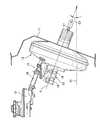
図1および図2は本発明の実施の形態を示すもので、図1は車両用ブレーキ装置の負圧ブースタおよびマスタシリンダを示す図、図2はマスタシリンダの拡大断面図である。尚、本明細書における前方および後方の定義は、マスタシリンダ側が前方であり、負圧ブースタ側が後方である。 1 and 2 show an embodiment of the present invention. FIG. 1 is a diagram showing a negative pressure booster and a master cylinder of a vehicle brake device, and FIG. 2 is an enlarged sectional view of the master cylinder. In addition, the definition of the front and back in this specification is that the master cylinder side is the front, and the negative pressure booster side is the back.
図1に示すように、自動車の運転席の前方のトーボード11の前面に負圧ブースタ12が支持されており、この負圧ブースタ12の前面にタンデム式のマスタシリンダ13が設けられる。マスタシリンダ13の上部に第1リザーバ14が一体に設けられており、第1リザーバ14は、その前上方に配置された第2リザーバ15にホース16を介して接続される。 As shown in FIG. 1, a
マスタシリンダ13の軸線Lを水平線Hに対して角度θ1だけ前上がりに配置し、かつリザーバを第1、第2リザーバ14,15に分割したことにより、狭隘なエンジンルームにおける負圧ブースタ12、マスタシリンダ13および第1、第2リザーバ14,15のレイアウトが容易になる。 Since the axis L of the
しかして、運転者が図示せぬブレーキペダルを踏むと、その踏力で負圧ブースタ12のプッシュロッド17が前方に押し込まれ、負圧ブースタ12で倍力された踏力によってマスタシリンダ13が作動することで、第1、第2出力ポート18,19から図示せぬホイールシリンダにブレーキ液圧を出力することができる。 Thus, when the driver steps on a brake pedal (not shown), the
図2に示すように、マスタシリンダ13は前端が閉塞された有底円筒状に形成されたシリンダ本体21を備えており、シリンダ本体21の前部および後部にそれぞれプライマリピストン22およびセカンダリピストン23が摺動自在に嵌合し、プライマリピストン22の前側に第1液圧室24が区画されるとともに、プライマリピストン22およびセカンダリピストン23間に第2液圧室25が区画される。 As shown in FIG. 2, the
シリンダ本体21の内周面に設けられた前側の第1カップシール26と後側の第2カップシール27とがプライマリピストン22の外周面に摺接しており、第1、第2カップシール26,27の間に第1リザーバ14に連通する第1入力ポート28が形成される。プライマリピストン22が最も後退した初期位置にあるとき、第1カップシール26の直後方に位置するように、プライマリピストン22に開口22a…が形成される。 A front
シリンダ本体21の底壁21aに配置したばね座29と、プライマリピストン22の前面に形成した凹部22bに配置したばね座30との間に、プライマリピストン22を後方に付勢する第1リターンスプリング31が縮設される。プライマリピストン22の前進を許容しながら後退限を規制すべく、前後のばね座29,30が、それらに対して摺動可能な連結ピン32で連結される。 A
シリンダ本体21の内周面に設けられた前側の第3カップシール33と後側の第4カップシール34とがセカンダリピストン23の外周面に摺接しており、第3、第4カップシール33,34の間に第1リザーバ14に連通する第2入力ポート35が形成される。セカンダリピストン23が最も後退した初期位置にあるとき、第3カップシール33の直後方に位置するように、セカンダリピストン23に開口23a…が形成される。 A front
プライマリピストン22の後面に形成した凹部22cの前後方向中間位置に段部22dが形成されており、この段部22dに支持したばね座36と、セカンダリピストン23の前面に形成した凹部23bに配置したばね座37との間に、セカンダリピストン23をプライマリピストン22に対して後方に付勢する第2リターンスプリング38が縮設される。セカンダリピストン23の前進を許容しながら後退限を規制すべく、後側のばね座37を摺動自在に貫通する連結ピン39の前端が前側のばね座36に螺合する。A
第1カップシール26、第3カップシール33および第4カップシール34は前向きに配置され、第2カップシール27は後向きに配置される。 The
従って、第1カップシール26により第1液圧室24にブレーキ液圧を発生させることができ、第2、第3カップシール27,33により第2液圧室25にブレーキ液圧を発生させることができ、また第4カップシール34によりシリンダ本体21からのブレーキ液の漏出を阻止することができる。 Accordingly, the brake fluid pressure can be generated in the first
しかして、運転者がブレーキペダルを踏むと負圧ブースタ12により作動するプッシュロッド17でセカンダリピストン23が前方に押圧され、その開口23a…が第3カップシール33を通過した瞬間に第2液圧室25に発生したブレーキ液圧が、第2出力ポート19を介してホイールシリンダに伝達される。また第2液圧室25に発生したブレーキ液圧によりプライマリピストン22が前方に押圧され、その開口22a…が第1カップシール26を通過した瞬間に第1液圧室24に発生したブレーキ液圧が、第1出力ポート18を介してホイールシリンダに伝達される。 Thus, when the driver steps on the brake pedal, the
運転者がブレーキペダルを戻すと、第1リターンスプリング31によりプライマリピストン22が後退するとともに、第2リターンスプリング38によりセカンダリピストン23が後退する。このとき、シリンダ本体21に対するプライマリピストン22の後退限は前後のばね座29,30および連結ピン32により規制され、かつプライマリピストン22に対するセカンダリピストン23の後退限、つまりシリンダ本体21に対するセカンダリピストン23の後退限は前後のばね座36,37および連結ピン39により規制される。 When the driver returns the brake pedal, the
プライマリピストン22の後面の凹部22cの内周面は、後方に向けて拡開する部分円錐状に形成されており、その凹部22cの内周面の上部は水平線Hに対して角度θ2だけ後上がりになっている。従って、第2液圧室25に発生した気泡は凹部22cに溜まることなく該凹部22cの外部に排出され、やがて第2出力ポート19を通過してブレーキキャリパに設けられたエア抜きブリーダから外部に排出される。これにより、前記凹部22cが臨む第2液圧室25がブレーキ液圧を発生するとき、気泡が圧縮されてペダルストロークが長くなったりブレーキ液圧が減少したりするのを防止することができる。 The inner peripheral surface of the concave portion 22c on the rear surface of the
また第2リターンスプリング38は、後側のばね座37に当接する後端の径が最大になり、前側のばね座36に当接する前端の径が最小になるように、後方から前方に向かって縮径している。仮に、第2リターンスプリング38が、その全長に亘って等径であるとすると、前側のばね座36に当接する部分の径が大きくなるために、凹部22cの内周面の上部が水平線Hに対して成す角度θ2を後上がりにできなくなる可能性があるが、第2リターンスプリング38を前向きに縮径したことで前側のばね座36に当接する部分の径を小さくし、凹部22cの内周面の上部が水平線Hに対して成す角度θ2を確実に後上がりにすることができる。 Further, the
しかも、第2リターンスプリング38の径が軸線L方向に変化するので、それを等径にした場合に比べて、圧縮変形時に第2リターンスプリング38の線材どうしが接触し難くなって圧縮可能量を増加させることができる。 In addition, since the diameter of the
以上、本発明の実施の形態を説明したが、本発明は上記実施の形態に限定されるものではなく、特許請求の範囲に記載された本発明を逸脱することなく種々の設計設定を行うことが可能である。 Although the embodiments of the present invention have been described above, the present invention is not limited to the above-described embodiments, and various design settings can be made without departing from the present invention described in the claims. Is possible.
例えば、第2リターンスプリング38は、その全体が前方に向かって縮径している必要はなく、プライマリピストン22の後面の凹部22cの内側に位置する部分だけを前方に向かって縮径しても良い。 For example, the
21 シリンダ本体
22 プライマリピストン
22c 凹部
22d段部
23 セカンダリピストン
36ばね座
38 第2リターンスプリング(リターンスプリング)
L 軸線
H 水平線21
36
L Axis line H Horizontal line
Claims (1)
Translated fromJapanese前記凹部(22c)の内周面上に前記リターンスプリング(38)の前端側を支持するためのばね座(36)が係合する段部(22d)を形成し、前記凹部(22c)の内周面を前記段部(22d)の外周から後方に向けて拡径するとともに、前記リターンスプリング(38)の外径を前方に向けて縮径することで、前記凹部(22c)の内周面の上部の傾きを水平線(H)よりも後上がりにしたことを特徴とするタンデム式マスタシリンダ。A primary piston (22) and a secondary piston (23) are slidably fitted to a cylinder body (21) having an axial line (L) arranged to rise forward, and a recess formed on the rear surface of the primary piston (22) ( 22c) and a tandem master cylinder in which a return spring (38) made of a coil spring is disposed between the secondary piston (23) and the front surface thereof.
A step portion (22d) that engages with a spring seat (36) for supporting the front end side of the return spring (38) is formed on the inner peripheral surface of the recess (22c). The diameterof the peripheral surface isincreasedfrom the outer periphery of the stepped portion (22d) toward the rear, andthe outer diameter of thereturn spring (38) is reduced toward the front , whereby the inner peripheral surface of the recess (22c). A tandem master cylinder characterized in that the inclination of the upper part of the cylinder is raised rearward from the horizontal line (H).
Priority Applications (1)
| Application Number | Priority Date | Filing Date | Title |
|---|---|---|---|
| JP2008217218AJP4892526B2 (en) | 2008-08-26 | 2008-08-26 | Tandem master cylinder |
Applications Claiming Priority (1)
| Application Number | Priority Date | Filing Date | Title |
|---|---|---|---|
| JP2008217218AJP4892526B2 (en) | 2008-08-26 | 2008-08-26 | Tandem master cylinder |
Publications (2)
| Publication Number | Publication Date |
|---|---|
| JP2010052496A JP2010052496A (en) | 2010-03-11 |
| JP4892526B2true JP4892526B2 (en) | 2012-03-07 |
Family
ID=42068879
Family Applications (1)
| Application Number | Title | Priority Date | Filing Date |
|---|---|---|---|
| JP2008217218AExpired - Fee RelatedJP4892526B2 (en) | 2008-08-26 | 2008-08-26 | Tandem master cylinder |
Country Status (1)
| Country | Link |
|---|---|
| JP (1) | JP4892526B2 (en) |
Family Cites Families (7)
| Publication number | Priority date | Publication date | Assignee | Title |
|---|---|---|---|---|
| US4228496A (en)* | 1976-09-07 | 1980-10-14 | Tandem Computers Incorporated | Multiprocessor system |
| JPS5847555A (en)* | 1981-09-17 | 1983-03-19 | Toshiba Corp | Die-casting mold for rotor of rotating electric machine |
| JPS59189910A (en)* | 1983-04-11 | 1984-10-27 | Ebara Corp | Substance separation apparatus by semi-permeable membrane |
| JPS63232063A (en)* | 1987-03-20 | 1988-09-28 | Tokico Ltd | master cylinder |
| JP2002037049A (en)* | 2000-07-26 | 2002-02-06 | Aisin Seiki Co Ltd | Brake master cylinder |
| JP4167145B2 (en)* | 2003-08-11 | 2008-10-15 | 日信工業株式会社 | Hydraulic master cylinder for vehicles |
| JP2007022368A (en)* | 2005-07-19 | 2007-02-01 | Advics:Kk | Master cylinder |
- 2008
- 2008-08-26JPJP2008217218Apatent/JP4892526B2/ennot_activeExpired - Fee Related
Also Published As
| Publication number | Publication date |
|---|---|
| JP2010052496A (en) | 2010-03-11 |
Similar Documents
| Publication | Publication Date | Title |
|---|---|---|
| JP6197098B2 (en) | Brake system for vehicles | |
| KR101418329B1 (en) | Master cylinder for brake system | |
| JP4892526B2 (en) | Tandem master cylinder | |
| JP2002321609A (en) | Master cylinder | |
| CN105539406B (en) | Master cylinder for braking system | |
| JP4206259B2 (en) | Master cylinder with negative pressure booster | |
| JP4690359B2 (en) | Center valve type hydraulic master cylinder | |
| US7530227B2 (en) | Brake apply master cylinder | |
| JP5528979B2 (en) | Brake device for vehicle | |
| JP6355101B2 (en) | Cylinder device and brake system | |
| JP4512032B2 (en) | Negative pressure booster | |
| JP4854575B2 (en) | Hydraulic master cylinder for vehicles | |
| JP5597448B2 (en) | Master cylinder | |
| KR20070065714A (en) | Plunger type master cylinder of vehicle brake system | |
| JP2005289180A (en) | Hydraulic master cylinder for vehicles | |
| JP4538775B2 (en) | Brake actuator | |
| JP4150644B2 (en) | Hydraulic master cylinder for vehicles | |
| JP4604376B2 (en) | Hydraulic brake device | |
| JP2008149743A (en) | Hydraulic master cylinder for vehicles | |
| JP2005206038A (en) | Master cylinder device | |
| JP5687020B2 (en) | Brake device for vehicle | |
| JP2020082973A (en) | Mater cylinder | |
| JP2001294145A (en) | Hydraulic booster | |
| JP2003341504A (en) | Master cylinder | |
| JP2001180473A (en) | Hydraulic booster for brake |
Legal Events
| Date | Code | Title | Description |
|---|---|---|---|
| A621 | Written request for application examination | Free format text:JAPANESE INTERMEDIATE CODE: A621 Effective date:20101125 | |
| A977 | Report on retrieval | Free format text:JAPANESE INTERMEDIATE CODE: A971007 Effective date:20110630 | |
| A131 | Notification of reasons for refusal | Free format text:JAPANESE INTERMEDIATE CODE: A131 Effective date:20110706 | |
| A521 | Written amendment | Free format text:JAPANESE INTERMEDIATE CODE: A523 Effective date:20110904 | |
| TRDD | Decision of grant or rejection written | ||
| A01 | Written decision to grant a patent or to grant a registration (utility model) | Free format text:JAPANESE INTERMEDIATE CODE: A01 Effective date:20111207 | |
| A01 | Written decision to grant a patent or to grant a registration (utility model) | Free format text:JAPANESE INTERMEDIATE CODE: A01 | |
| A61 | First payment of annual fees (during grant procedure) | Free format text:JAPANESE INTERMEDIATE CODE: A61 Effective date:20111219 | |
| R150 | Certificate of patent (=grant) or registration of utility model | Free format text:JAPANESE INTERMEDIATE CODE: R150 | |
| FPAY | Renewal fee payment (prs date is renewal date of database) | Free format text:PAYMENT UNTIL: 20141222 Year of fee payment:3 | |
| LAPS | Cancellation because of no payment of annual fees |