JP4892105B1 - Video processing device, video processing method, and video display device - Google Patents
Video processing device, video processing method, and video display deviceDownload PDFInfo
- Publication number
- JP4892105B1 JP4892105B1JP2011034995AJP2011034995AJP4892105B1JP 4892105 B1JP4892105 B1JP 4892105B1JP 2011034995 AJP2011034995 AJP 2011034995AJP 2011034995 AJP2011034995 AJP 2011034995AJP 4892105 B1JP4892105 B1JP 4892105B1
- Authority
- JP
- Japan
- Prior art keywords
- depth
- pixel block
- telop
- depth value
- probability
- Prior art date
- Legal status (The legal status is an assumption and is not a legal conclusion. Google has not performed a legal analysis and makes no representation as to the accuracy of the status listed.)
- Expired - Fee Related
Links
Images

Classifications
- H—ELECTRICITY
- H04—ELECTRIC COMMUNICATION TECHNIQUE
- H04N—PICTORIAL COMMUNICATION, e.g. TELEVISION
- H04N13/00—Stereoscopic video systems; Multi-view video systems; Details thereof
- H04N13/20—Image signal generators
- H04N13/261—Image signal generators with monoscopic-to-stereoscopic image conversion
Landscapes
- Engineering & Computer Science (AREA)
- Multimedia (AREA)
- Signal Processing (AREA)
- Testing, Inspecting, Measuring Of Stereoscopic Televisions And Televisions (AREA)
Abstract
Translated fromJapaneseDescription
Translated fromJapanese本発明の実施形態は、映像処理装置、映像処理方法および映像表示装置に関する。 Embodiments described herein relate generally to a video processing device, a video processing method, and a video display device.
近年、映像信号を立体的に表示する立体映像表示装置が普及しつつある。立体映像表示装置では、視点が異なる複数の視差画像が表示されており、左目と右目で異なる視差画像を見ることにより、映像信号が立体的に見える。 In recent years, stereoscopic video display devices that display video signals in three dimensions are becoming widespread. In the stereoscopic video display device, a plurality of parallax images with different viewpoints are displayed, and the video signal looks stereoscopically by viewing different parallax images between the left eye and the right eye.
表示装置によっては、表示可能な奥行き範囲の最前面あるいは最背面付近に表示される映像が二重に見えてしまうことがあり、特にテロップが二重に見えると非常に読みづらくなるという問題がある。 Depending on the display device, the image displayed at the forefront or near the back of the displayable depth range may appear double, especially when the telop is doubled, it is very difficult to read. .
テロップを高品位に立体表示可能な映像処理装置、映像処理方法および映像表示装置を提供する。 Provided are a video processing device, a video processing method, and a video display device capable of stereoscopically displaying telops with high quality.
実施形態によれば、映像表示装置は、テロップ検出部と、奥行き補正部と、視差画像生成部と、表示部とを備える。テロップ検出部は、入力画像における複数の画素からなる画素ブロックがテロップである確率を算出する。奥行き補正部は、予め定めた前記画素ブロックの奥行き値を、前記確率が高いほど前記奥行き値が奥行き中心に近づくように補正する。視差画像生成部は、前記補正された奥行き値に基づいて、前記入力画像の視差画像を生成する。表示部は、前記視差画像を立体表示する。 According to the embodiment, the video display device includes a telop detection unit, a depth correction unit, a parallax image generation unit, and a display unit. The telop detection unit calculates a probability that a pixel block including a plurality of pixels in the input image is a telop. The depth correction unit corrects the predetermined depth value of the pixel block so that the depth value approaches the depth center as the probability increases. The parallax image generation unit generates a parallax image of the input image based on the corrected depth value. The display unit stereoscopically displays the parallax image.
以下、実施形態について、図面を参照しながら具体的に説明する。
図1は、一実施形態に係る映像表示装置の概略ブロック図である。映像表示装置は、テロップ検出部1と、奥行き補正部2と、視差画像生成部3と、表示部4とを備えている。テロップ検出部1、奥行き補正部2および視差画像生成部3の少なくとも一部を映像処理装置として、例えば半導体チップにより構成してもよいし、これらの少なくとも一部をソフトウェアにより構成してもよい。Hereinafter, embodiments will be specifically described with reference to the drawings.
FIG. 1 is a schematic block diagram of a video display device according to an embodiment. The video display device includes a telop detection unit 1, a
テロップ検出部1は、入力画像における画素ブロックがテロップである確率pを算出する。奥行き補正部2は、予め定めた画素ブロックの奥行き値xを、確率pが高いほど奥行き値xが奥行き中心に近づくよう補正して、補正後の奥行き値x’を生成する。視差画像生成部3は、補正後の奥行き値x’に基づいて、入力画像の視差画像を生成する。表示部4は視差画像が立体的に見えるように表示する。 The telop detection unit 1 calculates a probability p that the pixel block in the input image is a telop. The
以下、各部の動作を詳しく説明する。 Hereinafter, the operation of each unit will be described in detail.
テロップ検出部1は、画素ブロックがテロップである確率pを算出する。画素ブロックは、入力画像における複数の画素からなる。画素ブロック内の画素数が少なすぎると確率pの精度が低下するが、多すぎるとテロップ検出部1の処理量が多くなる。これらを考慮し、例えば、画素ブロックは水平方向16画素×垂直方向16画素とする。ここで、テロップとは字幕やチャンネル表示等も含むものとする。 The telop detection unit 1 calculates a probability p that the pixel block is a telop. The pixel block is composed of a plurality of pixels in the input image. If the number of pixels in the pixel block is too small, the accuracy of the probability p decreases, but if it is too large, the processing amount of the telop detection unit 1 increases. Considering these, for example, the pixel block is 16 pixels in the horizontal direction × 16 pixels in the vertical direction. Here, the telop includes subtitles, channel display, and the like.
確率pの算出手法は種々考えられるが、一例として、予め、多数のサンプル画像を用いてテロップが多く表示される座標を学習しておき、当該画素ブロックの中心座標が学習された座標と近いほどテロップである確率pを高く設定してもよい。例えば字幕は画面の下側に表示されることが多いし、チャンネル表示は画面の右上や左上に表示されることが多い。したがって、テロップ検出部1は、これらの位置にある画素ブロックほど、テロップである確率pを高くすることができる。 Various methods for calculating the probability p are conceivable. As an example, by learning in advance the coordinates at which many telops are displayed using a large number of sample images, the closer the center coordinates of the pixel block are to the learned coordinates, The probability p that is a telop may be set high. For example, subtitles are often displayed at the bottom of the screen, and channel displays are often displayed at the upper right or upper left of the screen. Therefore, the telop detection unit 1 can increase the probability p of a telop for a pixel block at these positions.
また、予めサンプル画像を用いてテロップである画素ブロック内の輝度勾配を学習しておき、当該画素ブロック内の輝度勾配が学習された輝度勾配と近いほどテロップである確率pを高く設定してもよい。輝度勾配とは、例えば画素ブロック内の隣接する画素値の差の絶対値を積算した値である。 Alternatively, the luminance gradient in a pixel block that is a telop is learned in advance using a sample image, and the probability p that is a telop is set higher as the luminance gradient in the pixel block is closer to the learned luminance gradient. Good. The luminance gradient is a value obtained by integrating the absolute values of differences between adjacent pixel values in a pixel block, for example.
さらに、外部から画素ブロックの動きベクトルを受信し、動きベクトルの大きさが小さいほどテロップである確率pを高く設定してもよい。通常、テロップはほとんど移動しないためである。 Furthermore, the motion vector of the pixel block may be received from the outside, and the probability p of the telop may be set higher as the size of the motion vector is smaller. This is because usually the telop hardly moves.
また、文字認識を行ってテロップである確率pを算出してもよい。テロップの算出手法は上記のいずれかに限定されるわけではなく、上記の手法を組み合わせてもよいし、他の手法により確率pを算出してもよい。 Alternatively, the probability p that is a telop may be calculated by performing character recognition. The telop calculation method is not limited to any of the above, and the above methods may be combined, or the probability p may be calculated by another method.
奥行き補正部2は、外部から入力される予め定めた画素ブロックごとの奥行き値xを、テロップである確率pに基づいて補正する。奥行き値xは、どの程度、画素ブロックが表示部4の手前または奥に見えるよう表示するか、という情報を含む。 The
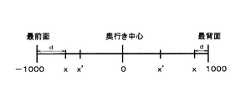
図2は、奥行き値xの一例を示す図である。本実施形態では、表示部4に対して最も手前(最前面)に表示される画素ブロックの奥行き値xを−1000、奥行き中心(表示部4上)に表示される画素ブロックの奥行き値xを0、表示部4に対して最も奥(最背面)に表示される画素ブロックの奥行き値xを1000とし、奥行き値xは−1000〜1000の値をとるものとする。 FIG. 2 is a diagram illustrating an example of the depth value x. In the present embodiment, the depth value x of the pixel block displayed on the foremost (frontmost) side with respect to the
奥行き値xは予め入力画像に付加されていてもよいし、奥行き生成部(不図示)を設けて、入力画像の特徴に基づいて奥行き値xを生成してもよい。奥行き値xを生成する場合、動きベクトルの大きさに基づいて奥行き値xを設定することができる。また、入力画像の色やエッジ等の特徴量から入力画像全体の構図を判定し、構図ごとに予め学習された映像の特徴量と比較して奥行き値xを算出してもよい。さらに、入力画像から人物の顔を検出し、検出された顔の位置や大きさに応じてテンプレートにあてはめて奥行き値xを算出してもよい。 The depth value x may be added to the input image in advance, or a depth generation unit (not shown) may be provided to generate the depth value x based on the characteristics of the input image. When generating the depth value x, the depth value x can be set based on the magnitude of the motion vector. Alternatively, the composition of the entire input image may be determined from the feature amount such as the color and edge of the input image, and the depth value x may be calculated by comparing with the feature amount of the video learned in advance for each composition. Furthermore, a face of a person may be detected from the input image, and the depth value x may be calculated by applying to a template according to the position and size of the detected face.
奥行き補正部2は、テロップである確率pが高いほど、奥行き値が0、すなわち、奥行き中心に近づくよう、奥行き値xを補正し、補正後の奥行き値x’を生成する。また、奥行き値xが最前面あるいは最背面に近いほどその補正量を大きくする。より具体的には以下のようにする。 The
テロップである確率pに基づく補正量rpを下記(1)式により定める。
また、最前面または最背面からの距離d=1000−|x|に基づく補正量rdを下記(2)式により定める。
さらに、補正量rp,rdに基づき、最終的な補正量rを下記(3)式により定め、さらに補正後の奥行き値x’を下記(4)式により定める。
r=rp*rd*rs ・・・(3)
x’=x*(1−r) ・・・(4)
ここで、rsは所定の定数(0〜1)である。補正量rは0〜1の値をとり、補正量rp,rdが大きいほど補正量rは大きくなる。定数rsは奥行き値の最大補正量を表し、例えばrs=0.3に設定すると、奥行き値の絶対値は最大で30%小さくなる。Further, based on the correction amounts rp and rd, the final correction amount r is determined by the following equation (3), and the corrected depth value x ′ is determined by the following equation (4).
r = rp * rd * rs (3)
x ′ = x * (1-r) (4)
Here, rs is a predetermined constant (0 to 1). The correction amount r takes a value from 0 to 1, and the correction amount r increases as the correction amounts rp, rd increase. The constant rs represents the maximum depth value correction amount. For example, when rs = 0.3, the absolute value of the depth value is reduced by 30% at the maximum.
なお、上述した補正後の奥行き値x’の算出手法は一例であり、これに限られるものではない。例えば、(1),(2)式に代えて線形な関数を用い、より簡易に補正量rp,rdを算出してもよい。 Note that the above-described method of calculating the corrected depth value x ′ is an example, and the present invention is not limited to this. For example, the correction amounts rp and rd may be calculated more simply by using linear functions instead of the equations (1) and (2).
補正後の奥行き値x’に基づき、視差画像生成部3は入力画像の視差画像を生成する。本実施形態の表示部4がめがね式の立体映像表示装置に用いられる場合、視差画像生成部3は左目用および右目用の2個の視差画像を生成する。また、裸眼式立体映像表示装置に用いられる場合、視差画像生成部3は、例えば9方向から見た9個の視差画像を生成する。例えば、左の方向から見た視差画像の場合、手前にある(すなわち補正後の奥行き値x’が小さい)画素ブロックは奥にある(すなわち補正後の奥行き値x’が大きい)画素ブロックより右側にずれて見える。そのため、補正後の奥行き値x’に基づき、視差画像生成部3は入力画像における手前にある画素ブロックを右側にずらす処理を行う。補正後の奥行き値x’が大きいほどずらす量を大きくする。そして、もともと画素ブロックがあった場所を周辺の画素を用いて適宜補間する。 Based on the corrected depth value x ′, the parallax
このようにして生成された視差画像を、表示部4は立体表示する。例えば、めがね式立体映像表示装置の場合、所定のタイミングで右目用の視差画像と左目用の視差画像を順繰りに表示する。また、裸眼式立体映像表示装置の場合、表示部上に例えばレンチキュラレンズ(不図示)が貼り付けられる。そして、表示部には複数の視差画像が同時に表示され、視聴者はレンチキュラレンズを介して、ある1つの視差画像を右目で見て、他の1つの視差画像を左目で見る。いずれの場合でも、右目と左目で異なる視差画像を見ることで、映像が立体的に見える。上記のように奥行き値xが補正されているため、最前面または最背面の近くにあり、テロップである確率pが高い画素ブロックはより奥行き中心の近くに表示される。 The
このように、本実施形態では、最前面または最背面の近くにあるテロップが奥行き中心に近づくよう奥行き値を補正する。結果として、テロップは最前面または最背面から離れた位置に表示されるため、二重に見えることが抑制される。したがって、テロップを高品位に立体表示できる。 As described above, in the present embodiment, the depth value is corrected so that the telop located near the forefront or near the back approaches the depth center. As a result, the telop is displayed at a position away from the foreground or the foreground, so that it is suppressed from appearing double. Therefore, the telop can be stereoscopically displayed with high quality.
本発明のいくつかの実施形態を説明したが、これらの実施形態は、例として提示したものであり、発明の範囲を限定することは意図していない。これら実施形態は、その他の様々な形態で実施されることが可能であり、発明の要旨を逸脱しない範囲で、種々の省略、置き換え、変更を行うことができる。これら実施形態やその変形は、発明の範囲や要旨に含まれると同様に、特許請求の範囲に記載された発明とその均等の範囲に含まれるものである。 Although several embodiments of the present invention have been described, these embodiments are presented by way of example and are not intended to limit the scope of the invention. These embodiments can be implemented in various other forms, and various omissions, replacements, and changes can be made without departing from the spirit of the invention. These embodiments and their modifications are included in the scope and gist of the invention, and are also included in the invention described in the claims and the equivalents thereof.
1 テロップ検出部
2 奥行き補正部
3 視差画像生成部
4 表示部1
Claims (11)
Translated fromJapanese予め定めた前記画素ブロックの奥行き値を、前記確率が高いほど前記奥行き値が奥行き中心に近づくように補正する奥行き補正部と、
前記補正された奥行き値に基づいて、前記入力画像の視差画像を生成する視差画像生成部と、
前記視差画像を立体表示する表示部と、を備える映像表示装置。A telop detection unit that calculates a probability that a pixel block including a plurality of pixels in the input image is a telop;
A depth correction unit that corrects the depth value of the predetermined pixel block so that the depth value approaches the depth center as the probability increases;
A parallax image generation unit that generates a parallax image of the input image based on the corrected depth value;
And a display unit that stereoscopically displays the parallax image.
x’=x*(1−r) ・・・(4)
ここで、pは前記テロップである確率、x,x’はそれぞれ補正前および後の前記奥行き値、dは補正前の前記奥行き値と奥行きの最前面または最背面との距離、pth,dth、rsはそれぞれ予め定めた定数。The video display device according to claim 1, wherein the depth correction unit corrects the depth value based on the following formulas (1) to (4).
x ′ = x * (1-r) (4)
Here, p is the probability of being the telop, x and x ′ are the depth values before and after correction, d is the distance between the depth value before correction and the front or back of the depth, pth, dth, rs is a predetermined constant.
予め定めた前記画素ブロックの奥行き値を、前記確率が高いほど前記奥行き値が奥行き中心に近づくように補正する奥行き補正部と、を備える映像処理装置。A telop detection unit that calculates a probability that a pixel block including a plurality of pixels in the input image is a telop;
And a depth correction unit configured to correct the depth value of the predetermined pixel block so that the depth value approaches the depth center as the probability increases.
x’=x*(1−r) ・・・(8)
ここで、pは前記テロップである確率、x,x’はそれぞれ補正前および後の前記奥行き値、dは補正前の前記奥行き値と奥行きの最前面または最背面との距離、pth,dth、rsはそれぞれ予め定めた定数。The video processing apparatus according to claim 6, wherein the depth correction unit corrects the depth value based on the following formulas (5) to (8).
x '= x * (1-r) (8)
Here, p is the probability of being the telop, x and x ′ are the depth values before and after correction, d is the distance between the depth value before correction and the front or back of the depth, pth, dth, rs is a predetermined constant.
予め定めた前記画素ブロックの奥行き値を、前記確率が高いほど前記奥行き値が奥行き中心に近づくよう、補正するステップと、を備える映像処理方法。Calculating a probability that a pixel block consisting of a plurality of pixels in the input image is a telop;
Correcting the predetermined depth value of the pixel block so that the depth value approaches the depth center as the probability increases.
Priority Applications (2)
| Application Number | Priority Date | Filing Date | Title |
|---|---|---|---|
| JP2011034995AJP4892105B1 (en) | 2011-02-21 | 2011-02-21 | Video processing device, video processing method, and video display device |
| US13/204,388US8390678B2 (en) | 2011-02-21 | 2011-08-05 | Image processing device, image processing method and display |
Applications Claiming Priority (1)
| Application Number | Priority Date | Filing Date | Title |
|---|---|---|---|
| JP2011034995AJP4892105B1 (en) | 2011-02-21 | 2011-02-21 | Video processing device, video processing method, and video display device |
Related Child Applications (1)
| Application Number | Title | Priority Date | Filing Date |
|---|---|---|---|
| JP2011272311ADivisionJP5395884B2 (en) | 2011-12-13 | 2011-12-13 | Video processing device, video processing method, and video display device |
Publications (2)
| Publication Number | Publication Date |
|---|---|
| JP4892105B1true JP4892105B1 (en) | 2012-03-07 |
| JP2012175370A JP2012175370A (en) | 2012-09-10 |
Family
ID=45907911
Family Applications (1)
| Application Number | Title | Priority Date | Filing Date |
|---|---|---|---|
| JP2011034995AExpired - Fee RelatedJP4892105B1 (en) | 2011-02-21 | 2011-02-21 | Video processing device, video processing method, and video display device |
Country Status (2)
| Country | Link |
|---|---|
| US (1) | US8390678B2 (en) |
| JP (1) | JP4892105B1 (en) |
Families Citing this family (3)
| Publication number | Priority date | Publication date | Assignee | Title |
|---|---|---|---|---|
| JP2010187916A (en)* | 2009-02-18 | 2010-09-02 | Fujifilm Corp | Image processing device, image processing system, and program |
| US9147278B2 (en)* | 2011-06-08 | 2015-09-29 | Panasonic Intellectual Property Management Co., Ltd. | Parallax image generation device, parallax image generation method, program, and integrated circuit |
| US10212407B2 (en)* | 2014-10-14 | 2019-02-19 | Koninklijke Philips N.V. | Processing a disparity of a three dimensional image |
Citations (7)
| Publication number | Priority date | Publication date | Assignee | Title |
|---|---|---|---|---|
| JPH0918798A (en)* | 1995-07-03 | 1997-01-17 | Sanyo Electric Co Ltd | Video display device with character processing function |
| JP2009135686A (en)* | 2007-11-29 | 2009-06-18 | Mitsubishi Electric Corp | 3D video recording method, 3D video recording medium, 3D video playback method, 3D video recording device, 3D video playback device |
| WO2010092823A1 (en)* | 2009-02-13 | 2010-08-19 | パナソニック株式会社 | Display control device |
| WO2010122775A1 (en)* | 2009-04-21 | 2010-10-28 | パナソニック株式会社 | Video processing apparatus and video processing method |
| JP2010273333A (en)* | 2009-04-21 | 2010-12-02 | Panasonic Corp | 3D image synthesizer |
| JP2011010128A (en)* | 2009-06-26 | 2011-01-13 | Canon Inc | Image reproducing apparatus, image capturing apparatus, and control method therefor |
| JP2011029849A (en)* | 2009-07-23 | 2011-02-10 | Sony Corp | Receiving device, communication system, method of combining caption with stereoscopic image, program, and data structure |
Family Cites Families (10)
| Publication number | Priority date | Publication date | Assignee | Title |
|---|---|---|---|---|
| US6366699B1 (en)* | 1997-12-04 | 2002-04-02 | Nippon Telegraph And Telephone Corporation | Scheme for extractions and recognitions of telop characters from video data |
| JP2004274125A (en) | 2003-03-05 | 2004-09-30 | Sony Corp | Image processing apparatus and method |
| JP2006325165A (en) | 2005-05-20 | 2006-11-30 | Excellead Technology:Kk | Device, program and method for generating telop |
| JP4157579B2 (en)* | 2006-09-28 | 2008-10-01 | シャープ株式会社 | Image display apparatus and method, image processing apparatus and method |
| CN105263012A (en)* | 2007-03-16 | 2016-01-20 | 汤姆森许可贸易公司 | System and method for combining text with three-dimensional content |
| EP2356818B1 (en)* | 2008-12-01 | 2016-04-13 | Imax Corporation | Methods and systems for presenting three-dimensional motion pictures with content adaptive information |
| TW201119353A (en)* | 2009-06-24 | 2011-06-01 | Dolby Lab Licensing Corp | Perceptual depth placement for 3D objects |
| JP5409281B2 (en)* | 2009-11-10 | 2014-02-05 | キヤノン株式会社 | Image processing apparatus and image processing method |
| US8605136B2 (en)* | 2010-08-10 | 2013-12-10 | Sony Corporation | 2D to 3D user interface content data conversion |
| US9035939B2 (en)* | 2010-10-04 | 2015-05-19 | Qualcomm Incorporated | 3D video control system to adjust 3D video rendering based on user preferences |
- 2011
- 2011-02-21JPJP2011034995Apatent/JP4892105B1/ennot_activeExpired - Fee Related
- 2011-08-05USUS13/204,388patent/US8390678B2/ennot_activeExpired - Fee Related
Patent Citations (7)
| Publication number | Priority date | Publication date | Assignee | Title |
|---|---|---|---|---|
| JPH0918798A (en)* | 1995-07-03 | 1997-01-17 | Sanyo Electric Co Ltd | Video display device with character processing function |
| JP2009135686A (en)* | 2007-11-29 | 2009-06-18 | Mitsubishi Electric Corp | 3D video recording method, 3D video recording medium, 3D video playback method, 3D video recording device, 3D video playback device |
| WO2010092823A1 (en)* | 2009-02-13 | 2010-08-19 | パナソニック株式会社 | Display control device |
| WO2010122775A1 (en)* | 2009-04-21 | 2010-10-28 | パナソニック株式会社 | Video processing apparatus and video processing method |
| JP2010273333A (en)* | 2009-04-21 | 2010-12-02 | Panasonic Corp | 3D image synthesizer |
| JP2011010128A (en)* | 2009-06-26 | 2011-01-13 | Canon Inc | Image reproducing apparatus, image capturing apparatus, and control method therefor |
| JP2011029849A (en)* | 2009-07-23 | 2011-02-10 | Sony Corp | Receiving device, communication system, method of combining caption with stereoscopic image, program, and data structure |
Also Published As
| Publication number | Publication date |
|---|---|
| US20120212478A1 (en) | 2012-08-23 |
| JP2012175370A (en) | 2012-09-10 |
| US8390678B2 (en) | 2013-03-05 |
Similar Documents
| Publication | Publication Date | Title |
|---|---|---|
| JP5849811B2 (en) | Video data generation method for autostereoscopic viewing | |
| US9270977B2 (en) | 3D photo creation system and method | |
| CN102117486B (en) | Generating three-dimensional figures is as the method and apparatus of data | |
| CN104601979B (en) | Multi-view image shows equipment and its control method | |
| US9922441B2 (en) | Image processing device, image processing method, and program | |
| JP5257248B2 (en) | Image processing apparatus and method, and image display apparatus | |
| US20130027391A1 (en) | Stereoscopic image system | |
| CN104081765A (en) | Image processing apparatus and image processing method thereof | |
| JPWO2015132828A1 (en) | Video display method and video display device | |
| JP2015154091A (en) | Image processing method, image processing device and electronic apparatus | |
| EP2498501A2 (en) | 3D image display method and apparatus thereof | |
| JP5127973B1 (en) | Video processing device, video processing method, and video display device | |
| JP4892105B1 (en) | Video processing device, video processing method, and video display device | |
| US8970670B2 (en) | Method and apparatus for adjusting 3D depth of object and method for detecting 3D depth of object | |
| US9756321B2 (en) | Three-dimensional image display device and method of displaying three dimensional image | |
| JP2014072809A (en) | Image generation apparatus, image generation method, and program for the image generation apparatus | |
| JP5765418B2 (en) | Stereoscopic image generation apparatus, stereoscopic image generation method, and stereoscopic image generation program | |
| US9380285B2 (en) | Stereo image processing method, stereo image processing device and display device | |
| JP5395884B2 (en) | Video processing device, video processing method, and video display device | |
| US20130181984A1 (en) | Apparatus and Method for Processing Three-Dimensional Image | |
| JP2014064187A (en) | Image processing device, image processing method, and image processing program | |
| CN102487447B (en) | The method and apparatus of adjustment object three dimensional depth and the method and apparatus of detection object three dimensional depth | |
| CN103313075A (en) | Image processing device, image processing method and non-transitory computer readable recording medium for recording image processing program | |
| WO2012165132A1 (en) | Autostereoscopic display device, viewpoint adjustment method, and method for generating autostereoscopically viewed video data | |
| JP2015154213A (en) | Projector device and projection method |
Legal Events
| Date | Code | Title | Description |
|---|---|---|---|
| TRDD | Decision of grant or rejection written | ||
| A01 | Written decision to grant a patent or to grant a registration (utility model) | Free format text:JAPANESE INTERMEDIATE CODE: A01 Effective date:20111122 | |
| A01 | Written decision to grant a patent or to grant a registration (utility model) | Free format text:JAPANESE INTERMEDIATE CODE: A01 | |
| A61 | First payment of annual fees (during grant procedure) | Free format text:JAPANESE INTERMEDIATE CODE: A61 Effective date:20111216 | |
| FPAY | Renewal fee payment (event date is renewal date of database) | Free format text:PAYMENT UNTIL: 20141222 Year of fee payment:3 | |
| LAPS | Cancellation because of no payment of annual fees |