JP4891672B2 - Screw parts fastening machine - Google Patents
Screw parts fastening machineDownload PDFInfo
- Publication number
- JP4891672B2 JP4891672B2JP2006182031AJP2006182031AJP4891672B2JP 4891672 B2JP4891672 B2JP 4891672B2JP 2006182031 AJP2006182031 AJP 2006182031AJP 2006182031 AJP2006182031 AJP 2006182031AJP 4891672 B2JP4891672 B2JP 4891672B2
- Authority
- JP
- Japan
- Prior art keywords
- torque
- drive
- screw
- speed
- driving
- Prior art date
- Legal status (The legal status is an assumption and is not a legal conclusion. Google has not performed a legal analysis and makes no representation as to the accuracy of the status listed.)
- Expired - Fee Related
Links
Images


Classifications
- B—PERFORMING OPERATIONS; TRANSPORTING
- B23—MACHINE TOOLS; METAL-WORKING NOT OTHERWISE PROVIDED FOR
- B23P—METAL-WORKING NOT OTHERWISE PROVIDED FOR; COMBINED OPERATIONS; UNIVERSAL MACHINE TOOLS
- B23P19/00—Machines for simply fitting together or separating metal parts or objects, or metal and non-metal parts, whether or not involving some deformation; Tools or devices therefor so far as not provided for in other classes
- B23P19/04—Machines for simply fitting together or separating metal parts or objects, or metal and non-metal parts, whether or not involving some deformation; Tools or devices therefor so far as not provided for in other classes for assembling or disassembling parts
- B23P19/06—Screw or nut setting or loosening machines
- B—PERFORMING OPERATIONS; TRANSPORTING
- B23—MACHINE TOOLS; METAL-WORKING NOT OTHERWISE PROVIDED FOR
- B23P—METAL-WORKING NOT OTHERWISE PROVIDED FOR; COMBINED OPERATIONS; UNIVERSAL MACHINE TOOLS
- B23P19/00—Machines for simply fitting together or separating metal parts or objects, or metal and non-metal parts, whether or not involving some deformation; Tools or devices therefor so far as not provided for in other classes
- B23P19/04—Machines for simply fitting together or separating metal parts or objects, or metal and non-metal parts, whether or not involving some deformation; Tools or devices therefor so far as not provided for in other classes for assembling or disassembling parts
- B23P19/06—Screw or nut setting or loosening machines
- B23P19/065—Arrangements for torque limiters or torque indicators in screw or nut setting machines
Landscapes
- Engineering & Computer Science (AREA)
- Mechanical Engineering (AREA)
- Details Of Spanners, Wrenches, And Screw Drivers And Accessories (AREA)
Description
Translated fromJapanese本発明は、ねじ、ボルトあるいはナット等のねじ部品を最初は高速回転でねじ込み、続いてあらかじめ設定した最終締結トルクでワークにねじ部品を締結するねじ部品締結機に関する。 The present invention relates to a screw component fastening machine that initially screws a screw component such as a screw, bolt, or nut at a high speed, and then fastens the screw component to a workpiece with a preset final fastening torque.
従来から一般的に良く知られているボルト、ナット、ねじ等の自動ねじ部品締結機は、これら部品を作業サイクル毎に自動供給し、これをワークに締め付けるようにした機械が良く知られている。このような機械にあって、その一例としてのねじ締め機は、ねじの頭部に形成された十字あるいは六角穴のような矩形形状の駆動穴に係合可能なビットを用い、このビットをビット駆動軸を介して電動ドライバに連結した構成である。このねじ締め機でワークにねじを締結する場合、ねじの駆動穴にビットを係合させた状態で電動ドライバを駆動する。これにより、ビットからねじに回転力が伝達され、ねじはワークに締結されるようになっている。 Conventionally well-known automatic screw parts fasteners such as bolts, nuts, and screws are well known machines that automatically supply these parts every work cycle and tighten them to a workpiece. . In such a machine, a screw tightening machine as an example uses a bit that can be engaged with a rectangular shaped drive hole such as a cross or a hexagon hole formed on the head of the screw, and this bit is used as a bit. It is the structure connected with the electric driver via the drive shaft. When a screw is fastened to a workpiece with this screw tightening machine, the electric driver is driven in a state where a bit is engaged with a drive hole of the screw. Thereby, a rotational force is transmitted from the bit to the screw, and the screw is fastened to the workpiece.
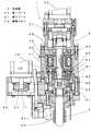
このようなねじ締め機は、高いねじ締め精度(バラツキの少ない締結トルク)を要求される所へのねじ締め作業には適しておらず、締結トルクを規定通りにする必要がある場合にはあまり採用されていない。そこで、このような締結トルクの安定した部品締結機として最近使用されつつあるねじ部品締結機としては、一例として図4に示すような締結機がある。これは特許文献1に示されているねじ締め機であり、チャックユニット(図示せず)にねじが保持されてから低速高トルクドライバ130及び高速低トルクドライバ110を同時に駆動する。このとき、ワンウェイクラッチ140により外輪141が内輪144に対してスリップするため、ドライバビット(図示せず)はドライバ軸105を介して高速低トルクドライバ110のみの回転を受けて回転し、ねじを高速で締め付けるようになっている。この動作において、ねじが締め付けられるにつれて高速低トルクドライバ110の回転数が低下して低速高トルクドライバ130の回転数よりも低下すると、ワンウェイクラッチ140の作用により低速高トルクドライバ130の回転をギア連結されているドライバ軸105に伝達し、低速で最終締結トルクまでねじ締めされるようになっている。
しかしながら、このようなねじ締め機においては、高速低トルクドライバと低速高トルクドライバとはスタート信号が入ると、どちらにも電流が流れて回転するようになっているため、現在のように省エネルギが求められている環境においては時代に逆行することになり、市場に受け容れられない。また、両方のトルクドライバが回転していることから、着座時の衝撃トルクは高くなっており、そのため、正確な最終締結トルクが得られない。更に、低速高トルクドライバの回転はギアにより連結されて駆動される構成のため、ねじ締め作業時の騒音が比較的高くなるとともにねじ締め完了時の衝撃も高くなっていた。その上、高速回転途中で低速回転に切り換わる構成であるから、この切り換わりがねじが着座するまでの位置であると、低速高トルクドライバでのねじ締め時間が長くなり、ねじ締め作業全体の作業時間が長くかかり作業コストの上昇を招いている。しかも、このねじの着座により回転動力伝達経路を変更する場合、ワークの下穴形状やねじ山形状によりこの着座トルクが変わることから、ワンウェイクラッチをその形状に応じて変更する必要があり、そのため、都度、これを交換する必要が生じるが、現実にはその対応ができない等の課題が生じている。 However, in such a screw tightening machine, when a start signal is input to the high speed low torque driver and the low speed high torque driver, both currents flow and rotate, so that energy saving is possible as in the present. In an environment where there is a demand, it will go backwards in time and will not be accepted by the market. Moreover, since both torque drivers are rotating, the impact torque at the time of seating is high, so that an accurate final fastening torque cannot be obtained. Furthermore, since the rotation of the low-speed high-torque driver is driven by being connected by a gear, the noise during screw tightening operation is relatively high and the impact at the time of screw tightening is high. In addition, since it is configured to switch to low-speed rotation in the middle of high-speed rotation, if this switching is the position until the screw is seated, the screw tightening time with the low-speed high-torque screwdriver becomes long, and the entire screw tightening work The work time is long and the work cost is increased. Moreover, when changing the rotational power transmission path by seating this screw, the seating torque will change depending on the pilot hole shape and thread shape of the workpiece, so it is necessary to change the one-way clutch according to the shape, This needs to be exchanged each time, but there are problems such as being unable to cope with it.
本発明の目的は、このような課題を解消するとともにねじ部品がワークに着座するときを基準にして、確実に駆動力の伝達経路を切り換え変更するようにしたねじ部品締結機を得ることである。 SUMMARY OF THE INVENTION An object of the present invention is to obtain a screw component fastening machine that eliminates such problems and reliably switches and changes the driving force transmission path based on when the screw component is seated on a workpiece. .
本発明の目的は、ねじ部品に係合してワークにねじ部品をねじ込むドライブ軸5と、このドライブ軸5に高速低トルクの駆動力を与える第1駆動手段と、前記高速低トルク駆動が終了したとき低速高トルクの駆動力を与える第2駆動手段とから構成されたねじ部品締結機において、第1駆動手段の第1出力軸11に第1プーリ20を固定し、前記ドライブ軸5を連結する伝達軸4に第2プーリ21を一体回転可能に固定してこの間に無端ベルト23を介在させて高速低トルク駆動する構成とし、一方、伝達軸4の延長線上の後方に最終締結トルクに達するまでは低速高トルク駆動する第2駆動手段を配置し、この第2駆動手段の第2出力軸32と伝達軸4との間にクラッチ部材40を介在させ、第1駆動手段での高速低トルクねじ込み作業によりねじ部品がワークに着座してストール状態になると、このストール状態の信号が出力されて第1駆動手段が停止し、これにより第2駆動手段での回転駆動に代わり、前記伝達軸の周囲に配置されたトルクセンサからの電気信号を検出しながら最終締結トルクに達するまで第2駆動手段が伝達軸4を回転駆動するよう制御を行う構成の制御部6に前記第1、第2駆動手段を電気接続し、前記制御部は、第1駆動手段に、ねじ部品がワークに着座してストール状態になったときに発生する衝撃トルクがねじ部品の種類に応じて設定される前記最終締結トルクを超えないような最高回転数を予め設定し、当該第1駆動手段を、当該最高回転数でねじ部品のねじ込み開始から着座まで駆動し続けるように制御するねじ部品締結機を提供することで達成される。An object of the present invention is to provide a
また、この目的を達成するために前記ねじ部品締結機の構成において、クラッチ部材は常時は噛み合いが外れ、第1駆動手段から第2駆動手段への回転切り換わり信号が入ると噛み合って、前記第2駆動手段からの回転駆動力が伝達軸4を介してドライブ軸5に伝達される構成であるから、この回転駆動伝達経路の切り換え変更が滑らかである。In order to achieve this object, in the configuration of the screw part fastening machine, the clutch member is always disengaged, and is engaged when a rotation switching signal from the first drive means to the second drive means is received, and the first Since the rotational driving force from the two driving means is transmitted to the
更に、これら構成におけるクラッチ部材40は一方が第2駆動手段の第2出力軸32に固定された固定クラッチ片41であって、他方は前記第2出力軸32に回転自在な可動クラッチ片44であって、この可動クラッチ片44は伝達軸4とともに回転可能な伝達部材48に噛み合っており、第1駆動手段の停止信号が入ると、固定クラッチ片41に可動クラッチ片44が電磁吸着され、伝達軸4に第2駆動手段からの駆動力が伝達される構成であるから、確実な回転動力伝達経路の切り換え変更ができる。Further, one of the clutch members 40 in these configurations is a fixed clutch piece 41 fixed to the second output shaft 32 of the second drive means, and the other is a movable clutch piece 44 that is rotatable on the second output shaft 32. The movable clutch piece 44 meshes with a transmission member 48 that can rotate together with the
しかも、これら構成に加えて、第2駆動手段は第2モータ30からの駆動力を低速高トルクの駆動力に変換するハーモニックドライブ(登録商標)減速機31を介して第2出力軸32に回転駆動力を伝達する構成であるので、大きな減速比が得られるとともにねじ部品の締結に十分な最終締結トルクも確実に得られる。Moreover, in addition to these configurations, the second driving means rotates to the second output shaft 32 via a harmonic drive (registered trademark) reduction gear 31 that converts the driving force from the
本発明によれば、ねじ部品がワークに確実に着座して高速低トルク用の第1駆動手段が確実にストール状態になると、第1駆動手段のトルクはゼロ状態になり、これと同時に切り換わって低速高トルク用の第2駆動手段が回転駆動するようになっているので、最終締結トルクが常に確実に得られるとともにねじ部品をワークに締結する締結作業時間が無駄なく短縮される。また、このねじ部品締結機は常時両方の駆動手段が回転駆動される構成ではなく、高速低トルク用の第1駆動手段が駆動しているときは低速高トルク用の第2駆動手段は回転駆動していないため、電力を無駄に消費することがなく、時代にあった省エネルギ効果が得られる。更に、従来のものは低速高トルクドライバがギアにより動力を伝達する構成であるが、本発明では、高速低トルク用の第1駆動手段が伝達軸をベルト駆動する構成であるから、高速回転駆動時の騒音が減少するとともに衝撃力も若干緩和されるので、比較的低い衝撃トルクが得られやすい。しかも、ねじ込み初期段階からねじ部品がワークに着座するまでは高速回転し、着座した後、確実に低速高トルク回転を伝達軸に伝達する構成であるから、ねじ部品の締結コストが低減されるとともに、従来のように、機械的なワンウェイクラッチを使用していないので、ワークの下穴形状やねじ山形状によりこの着座トルクが変わっても、電気的な処理を施すだけでよく、この着座による駆動手段の切り換え変更の調整が容易である等の特有の効果が得られる。According to the present invention, when the screw component is securely seated on the workpiece and the first driving means for high speed and low torque is surely stalled, the torque of the first driving means becomes zero and is switched at the same time. Since the second driving means for low speed and high torque is rotationally driven, the final fastening torque can always be obtained reliably and the fastening work time for fastening the screw component to the work can be shortened without waste. In addition, this screw component fastening machine does not always have a structure in which both driving means are rotationally driven. When the first driving means for high speed and low torque is driven, the second driving means for low speed and high torque is rotationally driven. Therefore, power is not consumed wastefully, and an energy saving effect suitable for the times can be obtained. Furthermore, the conventional one has a configuration in which a low-speed high-torque driver transmits power by means of gears. However, in the present invention, the first driving means for high-speed and low-torque is configured to drive the transmission shaft by belt, so that high-speed rotation drive is possible. Since the noise at the time is reduced and the impact force is slightly relaxed, it is easy to obtain a relatively low impact torque. In addition, since the screw component rotates at a high speed from the initial stage of screwing until the screw component is seated on the workpiece, and after being seated, the low-speed, high-torque rotation is reliably transmitted to the transmission shaft, the fastening cost of the screw component is reduced. Since conventional mechanical one-way clutches are not used, even if this seating torque changes due to the pilot hole shape or thread shape of the workpiece, it is only necessary to perform electrical processing. It is possible to obtain a specific effect such as easy adjustment of switching change of means.
以下本発明の実施の形態を図1乃至図3に基づき説明する。図2において、1は、昇降手段としての昇降台2に支持されているねじ部品締結機であり、このねじ部品締結機1はハウジング3で覆われている。このハウジング3には高速低トルク回転駆動する第1駆動手段としての第1モータ10が固定してあり、図1に示すように、この第1モータ10の第1出力軸11には第1プーリ20が固定されている。また、この第1出力軸11の中心線と平行な位置のもう一つの中心線上には前記第1駆動手段と平行な第2駆動手段としての第2モータ30が配置されている。この第2モータ30も前記ハウジング3に固定してあり、この第2モータ30にはこれの回転を低速高トルクに変換する減速機31が連結されている。この減速機31はハーモニックドライブ(登録商標)と呼ばれる構造を有しており、これは第2モータ30からの回転入力を低速高トルクの回転に変換して出力するようになっている。この構成は例えば、特開昭58−196349号あるいは特開昭59−113342号公報に開示されており、本発明出願以前に既に公知となっているので、これの説明は省略する。 Hereinafter, an embodiment of the present invention will be described with reference to FIGS. In FIG. 2,
これら第2モータ30とハーモニックドライブ機構の減速機31とは最終締結トルクに達するまで低速高トルク回転駆動する第2駆動手段を構成しており、この第2駆動手段の第2出力軸32にはクラッチ部材40を構成する固定クラッチ片41が前記第2出力軸32と一体に回転するよう固定されている。この固定クラッチ片41内には円筒形状の電磁石46を内蔵する保持ブロック43が前記ハウジング3に固定してあり、前記固定クラッチ片41は保持ブロック43に対して回転可能となっている。この固定クラッチ片41の下端外周近くにはクラッチ歯42が形成してあり、これに対向する位置にはこのクラッチ歯42と必要に応じて噛み合うもう一方のクラッチ歯45を有する可動クラッチ片44が設けられている。この可動クラッチ片44は前記第2出力軸32に対して回転自在となっており、常時はスプリング(図示せず)により噛み合いが外れるようになっている。そして、この可動クラッチ片44は前記固定クラッチ片41内の電磁石46に電流が流れると、固定クラッチ片41に電磁吸着されて互いのクラッチ歯42、45が噛み合う構成であり、第1駆動手段から第2駆動手段への回転切り換わり信号が入ることで、噛み合うようになっている。 The
更に、この可動クラッチ片44の反対側には内方を向いた内歯47が外周に沿い全周に渡って形成してあり、この内歯47には前記第2出力軸32の先端側の周囲に回転自在に支持されている環状の伝達部材48の外周縁に形成した外歯49に噛み合い且つ前記可動クラッチ片44の内歯47が前記外歯49に沿い移動自在になっている。この伝達部材48には外周に第2プーリ21を固定したプーリ固定部材22が一体回転可能に固定してあり、このプーリ固定部材22は前記第2出力軸32と同一中心線延長上に配置されている伝達軸4に回転駆動力を伝達可能に図3に示すように、噛み合い接続されている。 Further, on the opposite side of the movable clutch piece 44, an
一方、前記第1プーリ20と第2プーリ21との間には、無端ベルト23が介在しており、この無端ベルト23は前記第1駆動手段の高速低トルク回転を伝達軸4に伝達するようになっている。しかも、この伝達軸4は図2に示すように、その先端が前記昇降台2を貫通してねじ部品(図示せず)に係合するボックスビットあるいは十字ビット等のねじ部品締結部材(図示せず)を有するドライブ軸5に連結されている。 On the other hand, an
その上、前記伝達軸4の周囲にはこれを覆う筒状の起歪管50が前記ハウジング3に固定配置してあり、この起歪管50は、前記伝達軸4の先端に連結されたドライブ軸5に係合しているねじ部品が高トルクで締結されるときに発生する反力を受けるようになっており、この反力によって当該起歪管50は捻れるように構成されている。また、この起歪管50には捻れに応じた歪みを電気信号として検出する歪みゲージ51が取付けられている。これら起歪管50、歪みゲージ51によりトルクセンサが構成され、歪ゲージ51の信号から制御部6において締結トルクが判定され、所定締結トルクが得られるようになっている。In addition, a cylindrical
また、前記第1、第2駆動手段は、夫々の第1出力軸11、第2出力軸32からの信号を出力するようになっており、この信号は前記制御部6に入り、前記センサからの信号とともに処理されるようになっている。更に、制御部6は前記クラッチ部材40への電流を入り切りする信号を出力するようになっており、これは第1駆動手段のストール状態(ストールとは、第1駆動手段の第1出力軸が回転不可により回転できなくなる現象を指す。)における信号を出力するものであり、これにより、第2駆動手段からの低速高トルク駆動が伝達されることになる。しかも、この制御部6は、ねじ部品の種類に応じて設定されている最終締結トルクに対して、第1駆動手段によりねじ部品が高速回転でねじ込まれて、ねじ部品がワークに着座してストール状態になると、発生する衝撃トルクが前記最終締結トルクを超えないよう第1駆動手段の最高回転数を決定する構成ともなっている。 The first and second driving means output signals from the first output shaft 11 and the second output shaft 32, respectively. These signals enter the
次に、本発明の作用を説明すると、ねじ部品を保持した状態のねじ部品締結部材を有するねじ部品締結機において、ワークの締結位置にねじ部品を位置させてから、スタート信号が入ると、昇降台2が前進する。この後、第1駆動手段の第1モータ10が回転し、第1出力軸11から第1プーリ20に回転が伝達される。この第1駆動手段は高速低トルク回転であることから第1プーリ20から無端ベルト23を介して第2プーリ21が回転され、伝達軸4に回転が伝達される。このとき、第2駆動手段の第2出力軸32と伝達軸4とはクラッチ部材40で連結が遮断されているので、何らの抵抗なくドライブ軸5は高速回転し、ねじ部品はワークにねじ込まれる。 Next, the operation of the present invention will be described. In a screw component fastening machine having a screw component fastening member in a state where the screw component is held, when the screw component is positioned at the workpiece fastening position, when the start signal is input, The
このようにして、ねじ部品が高速回転でねじ込まれてワークにねじ部品が着座すると、第1駆動手段の第1モータ10はストール状態となり、第2駆動手段の第2モータ30に制御部6でのスタート信号が入るとともにクラッチ部材40にも電流が流れてON状態となり、クラッチ部材40の可動クラッチ片44は固定クラッチ片41に電磁吸着されて互いのクラッチ歯42、45が噛み合い、第2駆動手段からの低速高トルクの回転が伝達可能となる。このクラッチ部材40の回転は伝達部材48、第2プーリ21が固定されているプーリ固定部材22を介して伝達軸4に伝わり、ねじ部品締結部材を有するドライブ軸5によりねじ部品はワークに締結される。この低速高トルクの回転中において、トルクセンサにより締結トルクがあらかじめ所定値に設定されている最終締結トルクに達すると、締結完了となる。 In this way, when the screw component is screwed in at a high speed and the screw component is seated on the workpiece, the
このねじ部品の締結作業において、第1駆動手段によるストール状態は最終締結トルクより低い衝撃トルクで発生するように制御部6により駆動制御されているので、第1駆動手段での慣性は小さいものとなり、最終締結トルクが第2駆動手段により正確に得られることになる。このことから第1駆動手段でのねじ締め開始からワークに着座するまでの締結作業を高速回転で行うことができる。 In the fastening operation of the threaded parts, the
一方、制御部6は第1駆動手段での高速低トルクねじ込み作業によりねじ部品がワークに着座してストール状態になると、第1駆動手段での伝達軸4の回転駆動に代わって、第2駆動手段が最終締結トルクに達するまで伝達軸4を回転駆動するよう制御を行うようになっており、このストール状態を検出して第1、第2駆動手段を制御するとともに、ねじ部品が着座して最終締結トルクに達したか否かを判定している。このように第1駆動手段、第2駆動手段、クラッチ部材40、トルクセンサ等の信号を制御部6との間で送受信することによって締結作業を総合的に制御することで、ねじ部品の締結を効率よく行うことになる。On the other hand, when the threaded part is seated on the workpiece by the high-speed and low-torque screwing operation by the first driving means and becomes in a stalled state, the
この後、ねじ部品の締結作業サイクルが完了すると、昇降台2が後退し、元の位置に戻る。このときクラッチ部材40は電磁吸着信号がOFF状態となり、可動クラッチ片44は固定クラッチ片41との噛み合いが外れ、元の状態に復帰して次の作業サイクルまでの待機状態となっている。 Thereafter, when the screw component fastening operation cycle is completed, the
尚、この実施の形態における第1駆動手段からの回転伝達経路は、ベルト駆動となっているので、トルクセンサからの信号線はこの空間を有効に利用して配線することができ、そのため、ハウジング3内に収納可能となり、部品締結機全体がコンパクトになる。また、無端ベルト23を介して高速回転が伝達されているので、これの僅かな延びも期待できることから衝撃トルクが僅かではあるが緩和されるとともに騒音も減少する。 Since the rotation transmission path from the first drive means in this embodiment is belt-driven, the signal line from the torque sensor can be wired effectively using this space, so that the
1 ねじ部品締結機
2 昇降台
3 ハウジング
4 伝達軸
5 ドライブ軸
6 制御部
10 第1モータ
11 第1出力軸
20 第1プーリ
21 第2プーリ
22 プーリ固定部材
23 無端ベルト
30 第2モータ
31 減速機
32 第2出力軸
40 クラッチ部材
41 固定クラッチ片
42 クラッチ歯
43 保持ブロック
44 可動クラッチ片
45 クラッチ歯
46 電磁石
47 内歯
48 伝達部材
49 外歯
50 起歪管
51 歪みゲージDESCRIPTION OF
Claims (4)
Translated fromJapanesePriority Applications (4)
| Application Number | Priority Date | Filing Date | Title |
|---|---|---|---|
| JP2006182031AJP4891672B2 (en) | 2006-06-30 | 2006-06-30 | Screw parts fastening machine |
| KR1020070061374AKR20080003244A (en) | 2006-06-30 | 2007-06-22 | Screw parts fasteners |
| PCT/JP2007/063134WO2008001893A1 (en) | 2006-06-30 | 2007-06-29 | Screw part fastening machine |
| US11/824,332US7413029B2 (en) | 2006-06-30 | 2007-07-02 | Screw fastening machine |
Applications Claiming Priority (1)
| Application Number | Priority Date | Filing Date | Title |
|---|---|---|---|
| JP2006182031AJP4891672B2 (en) | 2006-06-30 | 2006-06-30 | Screw parts fastening machine |
Publications (3)
| Publication Number | Publication Date |
|---|---|
| JP2008006560A JP2008006560A (en) | 2008-01-17 |
| JP2008006560A5 JP2008006560A5 (en) | 2008-02-28 |
| JP4891672B2true JP4891672B2 (en) | 2012-03-07 |
Family
ID=38845656
Family Applications (1)
| Application Number | Title | Priority Date | Filing Date |
|---|---|---|---|
| JP2006182031AExpired - Fee RelatedJP4891672B2 (en) | 2006-06-30 | 2006-06-30 | Screw parts fastening machine |
Country Status (4)
| Country | Link |
|---|---|
| US (1) | US7413029B2 (en) |
| JP (1) | JP4891672B2 (en) |
| KR (1) | KR20080003244A (en) |
| WO (1) | WO2008001893A1 (en) |
Families Citing this family (25)
| Publication number | Priority date | Publication date | Assignee | Title |
|---|---|---|---|---|
| EP2030709A3 (en)* | 2007-08-29 | 2013-01-16 | Positec Power Tools (Suzhou) Co., Ltd. | Power tool |
| US9016398B2 (en)* | 2008-12-04 | 2015-04-28 | Ingersoll-Rand Company | Disc-shaped torque transducer |
| JP2012121126A (en)* | 2010-12-10 | 2012-06-28 | Nitto Seiko Co Ltd | Screw part fastener |
| CN102695588A (en)* | 2009-12-17 | 2012-09-26 | 日东精工株式会社 | Threaded fastener tightening and loosening device |
| CN102139477A (en)* | 2010-02-01 | 2011-08-03 | 有限会社井出计器 | Screw tightening diagnostic device and electric driver |
| US8869656B2 (en)* | 2011-11-04 | 2014-10-28 | Senco Brands, Inc. | Screwdriver tool with improved corner fit function |
| EP2782713B1 (en)* | 2011-11-04 | 2020-01-08 | Kyocera Senco Industrial Tools, Inc. | Screwdriver tool with improved corner fit function |
| FR2983107B1 (en)* | 2011-11-25 | 2014-12-05 | Renault Georges Ets | SPINDLE TYPE ELECTRIC SCREWDRIVER TO BE FIXED ON A BUILDING. |
| CN102678834B (en)* | 2012-05-25 | 2016-03-02 | 衡阳市锦泰工具有限公司 | A kind of replacer special for laminated spring bolt of electric |
| EP3079500B1 (en)* | 2013-12-12 | 2019-06-19 | Nestec S.A. | Synthetic milk compositions for optimal growth and development and prevention of obesity in male and female infant and children |
| DE102014208989A1 (en)* | 2014-05-13 | 2015-11-19 | Deprag Schulz Gmbh U. Co | Method for direct screwing of components, in particular for flow hole screwing and device for direct screwing of components |
| WO2016055891A2 (en)* | 2014-10-07 | 2016-04-14 | Paramasivan Arvind Kumar Tirchirapolly | Automated fastener assembly |
| CN105345418B (en)* | 2015-10-16 | 2017-09-22 | 诸暨市润拓机械自动化科技有限公司 | Valve element is selected to finding mechanism accurately |
| KR101759301B1 (en)* | 2016-01-11 | 2017-08-01 | 계양전기 주식회사 | Control method of electrically-drive tool |
| CN106425440B (en)* | 2016-11-23 | 2019-01-22 | 合肥智博生物科技有限公司 | It is a kind of with the Full automatic rotating disc type screw locking machine for moving back screw function |
| CN106312536B (en)* | 2016-11-23 | 2019-01-04 | 安徽继远软件有限公司 | A kind of Full automatic rotating disc type screw locking machine with riveting screw function |
| CN107414470B (en)* | 2017-07-28 | 2023-08-15 | 东莞市富勤自动化设备有限公司 | Automatic torsion adjusting and measuring machine |
| US10926368B2 (en)* | 2017-09-27 | 2021-02-23 | Ingersoll-Rand Industrial U.S., Inc. | Part illumination status lights |
| US11040421B2 (en)* | 2018-10-26 | 2021-06-22 | Forum Us, Inc. | Torque tool with electric motors |
| US11273541B2 (en) | 2019-03-18 | 2022-03-15 | Kyocera Senco Industrial Tools, Inc. | Autofeed screwdriver attachment with twist collar to activate movable plates for latching to screw gun |
| WO2022221050A1 (en)* | 2021-04-16 | 2022-10-20 | Black & Decker Inc. | Electrostatic clutch for power tool |
| US12214567B2 (en) | 2021-09-08 | 2025-02-04 | PDInnovative LLC | Press machine having planetary gear system for multi-speed drive functionality |
| US11819906B2 (en) | 2021-09-21 | 2023-11-21 | PDInnovative LLC | Linear-actuated press machine having multiple motors and clutch system for multi-speed drive functionality |
| US11919267B2 (en) | 2021-09-21 | 2024-03-05 | PDInnovative LLC | Linear-actuated press machine having telescopic drive configuration for multi-speed drive functionality |
| CN114473940B (en)* | 2021-12-31 | 2024-03-12 | 湖北清江水电开发有限责任公司 | Automatic adjusting tool for guide shaft bush gap of hydraulic generator |
Family Cites Families (21)
| Publication number | Priority date | Publication date | Assignee | Title |
|---|---|---|---|---|
| US4058884A (en)* | 1976-10-18 | 1977-11-22 | Lydon Ralph P | Automatic screw driver system and method for utilizing same |
| JPS594262B2 (en)* | 1979-06-19 | 1984-01-28 | 芝浦メカトロニクス株式会社 | bolt tightening machine |
| JPS56157965A (en)* | 1980-05-12 | 1981-12-05 | Shibaura Eng Works Ltd | Clamping machine for bolt |
| JPS5856771A (en)* | 1981-09-25 | 1983-04-04 | 芝浦メカトロニクス株式会社 | Electric bolt tightening machine |
| JPS5969273A (en)* | 1982-10-12 | 1984-04-19 | 三菱電機株式会社 | Clamping machine for screw |
| JPS6052268A (en) | 1983-08-31 | 1985-03-25 | 日東精工株式会社 | screw tightening machine |
| JPS6474070A (en)* | 1987-09-11 | 1989-03-20 | Mitsubishi Electric Corp | Leak current reducing circuit |
| US5231902A (en)* | 1991-06-10 | 1993-08-03 | Hitachi Koki Co. Ltd. | Pneumatically operated screw driver |
| US5170852A (en)* | 1992-05-11 | 1992-12-15 | Nitto Seiko Co., Ltd. | Automatic screw fastening machine |
| JPH0724746A (en)* | 1993-07-13 | 1995-01-27 | Sony Corp | Clutch mechanism and screwing driver using said mechanism and screwing device |
| JPH07100772A (en)* | 1993-10-01 | 1995-04-18 | Ricoh Co Ltd | Rotary power tools |
| US5595251A (en)* | 1994-08-10 | 1997-01-21 | The United States Of America As Represented By The Administrator Of The National Aeronautics And Space Administration | Displaceable gear torque controlled driver |
| JPH0866874A (en)* | 1994-08-26 | 1996-03-12 | Nittetsu Muroran Eng Kk | Bolt fastener |
| US5730035A (en)* | 1995-06-09 | 1998-03-24 | Hitachi Koki Co., Ltd. | Pneumatically operated screw driver |
| JP3628486B2 (en)* | 1997-06-30 | 2005-03-09 | 株式会社マキタ | Screw tightener clutch |
| GB9810746D0 (en)* | 1998-05-19 | 1998-07-15 | Multi Automation Limited | Fastening apparatus |
| KR100545408B1 (en)* | 2000-10-18 | 2006-01-24 | 마크스 가부시기가이샤 | Air impact driver |
| EP1459849B1 (en)* | 2001-08-08 | 2011-12-21 | Max Co., Ltd. | Safety device of air impact screwdriver |
| JP4340085B2 (en) | 2003-03-20 | 2009-10-07 | 日東精工株式会社 | Screw tightening device |
| JP4089584B2 (en)* | 2003-10-01 | 2008-05-28 | 日立工機株式会社 | Compressed air screwing machine |
| US6942042B2 (en)* | 2003-11-12 | 2005-09-13 | De Poan Pneamatic Corp. | Pneumatic motor-controlled valve of screwdriver |
- 2006
- 2006-06-30JPJP2006182031Apatent/JP4891672B2/ennot_activeExpired - Fee Related
- 2007
- 2007-06-22KRKR1020070061374Apatent/KR20080003244A/ennot_activeCeased
- 2007-06-29WOPCT/JP2007/063134patent/WO2008001893A1/enactiveSearch and Examination
- 2007-07-02USUS11/824,332patent/US7413029B2/ennot_activeExpired - Fee Related
Also Published As
| Publication number | Publication date |
|---|---|
| JP2008006560A (en) | 2008-01-17 |
| US7413029B2 (en) | 2008-08-19 |
| KR20080003244A (en) | 2008-01-07 |
| US20080000333A1 (en) | 2008-01-03 |
| WO2008001893A1 (en) | 2008-01-03 |
Similar Documents
| Publication | Publication Date | Title |
|---|---|---|
| JP4891672B2 (en) | Screw parts fastening machine | |
| JP4211675B2 (en) | Impact rotary tool | |
| JP5201842B2 (en) | Screwdriver torque detection device for electric screwdriver | |
| WO2011074543A1 (en) | Threaded fastener tightening and loosening device | |
| EP1595649A2 (en) | Rotary impact tool | |
| JP2006000993A (en) | Fastening machine with reaction receiver | |
| JP2011173233A (en) | Screw tightening diagnostic device and electric driver | |
| JP4986640B2 (en) | Constant torque electric screwdriver | |
| JP6309369B2 (en) | Nut tightening machine | |
| JP5363965B2 (en) | Screw parts tightening device | |
| JP6617959B2 (en) | Method and apparatus for detecting screw tightening torque of constant torque electric screwdriver | |
| JP2009160709A (en) | Screw parts fastening machine | |
| JP3130851U (en) | Handy type clamping machine with reaction force receiver | |
| JP2015512796A (en) | Electric wrench | |
| JP5204747B2 (en) | Screw parts fastening machine | |
| JP2008114303A (en) | Screw parts fastening machine | |
| JP4340085B2 (en) | Screw tightening device | |
| CN108687705B (en) | Assembly method of torsion shear wrench | |
| JPH04336980A (en) | Power tool | |
| JP2010260111A (en) | Rotation transmission device for screw parts automatic fastening machine | |
| JP2010184342A (en) | Automatic screw part fastening machine | |
| JP2012045679A (en) | Automatic screw fastening machine | |
| CN111168616A (en) | Control system of rechargeable torque wrench | |
| JP2010284739A (en) | Power transmission device for automatic fastening machine for screw parts | |
| JP2012121125A (en) | Screw part fastener |
Legal Events
| Date | Code | Title | Description |
|---|---|---|---|
| A521 | Written amendment | Free format text:JAPANESE INTERMEDIATE CODE: A523 Effective date:20071226 | |
| A621 | Written request for application examination | Free format text:JAPANESE INTERMEDIATE CODE: A621 Effective date:20090116 | |
| A131 | Notification of reasons for refusal | Free format text:JAPANESE INTERMEDIATE CODE: A131 Effective date:20111018 | |
| A521 | Written amendment | Free format text:JAPANESE INTERMEDIATE CODE: A523 Effective date:20111104 | |
| TRDD | Decision of grant or rejection written | ||
| A01 | Written decision to grant a patent or to grant a registration (utility model) | Free format text:JAPANESE INTERMEDIATE CODE: A01 Effective date:20111209 | |
| A01 | Written decision to grant a patent or to grant a registration (utility model) | Free format text:JAPANESE INTERMEDIATE CODE: A01 | |
| A61 | First payment of annual fees (during grant procedure) | Free format text:JAPANESE INTERMEDIATE CODE: A61 Effective date:20111216 | |
| R150 | Certificate of patent or registration of utility model | Free format text:JAPANESE INTERMEDIATE CODE: R150 | |
| FPAY | Renewal fee payment (event date is renewal date of database) | Free format text:PAYMENT UNTIL: 20141222 Year of fee payment:3 | |
| LAPS | Cancellation because of no payment of annual fees |