JP4889578B2 - Mobile terminal - Google Patents
Mobile terminalDownload PDFInfo
- Publication number
- JP4889578B2 JP4889578B2JP2007161687AJP2007161687AJP4889578B2JP 4889578 B2JP4889578 B2JP 4889578B2JP 2007161687 AJP2007161687 AJP 2007161687AJP 2007161687 AJP2007161687 AJP 2007161687AJP 4889578 B2JP4889578 B2JP 4889578B2
- Authority
- JP
- Japan
- Prior art keywords
- frequency
- antenna
- terminal
- impedance
- mobile terminal
- Prior art date
- Legal status (The legal status is an assumption and is not a legal conclusion. Google has not performed a legal analysis and makes no representation as to the accuracy of the status listed.)
- Expired - Fee Related
Links
Images


Landscapes
- Details Of Aerials (AREA)
- Support Of Aerials (AREA)
- Transceivers (AREA)
Description
Translated fromJapanese 本発明は、アンテナと、高周波増幅回路と、インピーダンスのマッチング回路と
を備える移動端末、及び移動端末のアンテナ制御方法に関する。The present invention relates to a mobile terminal including an antenna, a high frequency amplifier circuit, and an impedance matching circuit, and an antenna control method for the mobile terminal.
従来、携帯電話端末などの移動端末では、使用状態によってアンテナの特性インピーダンスが変化すると、無線信号の送受信性能に大きな影響が生じる。 Conventionally, in a mobile terminal such as a mobile phone terminal, when the characteristic impedance of the antenna changes depending on the usage state, the radio signal transmission / reception performance is greatly affected.
このようなアンテナの特性インピーダンスの変化による送受信性能の劣化を検出する方法が知られている。例えば、無線通信装置(無線基地局)が、検波信号のレベル変動に基づいて、アンテナの特性インピーダンスと給電側(高周波増幅回路)のインピーダンスとの不整合の要因、具体的には、アンテナの接続端子の外れや破損など、アンテナの異常を検出する方法が提案されている(特許文献1参照)。
ところで、移動端末の場合、アンテナの異常に限らず、移動端末の使用状態によってアンテナの特性インピーダンスが変化するといった問題がある。 By the way, in the case of a mobile terminal, there is a problem that the characteristic impedance of the antenna changes depending on the usage state of the mobile terminal, not limited to the abnormality of the antenna.
例えば、移動端末の近傍に人間が居る場合と、金属製の物体がある場合とでは、アンテナの特性インピーダンスが変化する。さらに、折り畳み式の移動端末では、折り畳まれた状態と、広げられた状態とでは、アンテナの特性インピーダンスが変化する。 For example, the characteristic impedance of the antenna changes between when a human is near the mobile terminal and when a metal object is present. Further, in the folding mobile terminal, the characteristic impedance of the antenna changes between the folded state and the unfolded state.
また、アンテナの特性インピーダンスが変化すると、アンテナの共振周波数、つまり、アンテナを介して受信した無線信号の中心周波数も変化する。 Further, when the characteristic impedance of the antenna changes, the resonance frequency of the antenna, that is, the center frequency of the radio signal received via the antenna also changes.
すなわち、上述した従来の方法では、単に、検波信号のレベル変動に基づいてアンテナの異常を検出しているだけである。このため、移動端末の使用状態によって変化するアンテナの特性インピーダンスや共振周波数などの特性変化を検出し、変化した特性インピーダンスや共振周波数に適応することができないといった問題があった。 That is, in the conventional method described above, the antenna abnormality is simply detected based on the level fluctuation of the detection signal. For this reason, there has been a problem that it is impossible to detect characteristic changes such as the characteristic impedance and resonance frequency of the antenna that change depending on the usage state of the mobile terminal, and to adapt to the changed characteristic impedance and resonance frequency.
本発明は、このような状況に鑑みてなされたものであり、使用状態に応じて変化するアンテナの特性変化を検出し、変化するアンテナの特性に適応することによって送受信性能の劣化を抑制できる移動端末及びアンテナ制御方法を提供することを目的とする。 The present invention has been made in view of such a situation, and is capable of detecting a change in antenna characteristics that changes according to the use state and adapting to the changing antenna characteristics to suppress deterioration in transmission and reception performance. An object is to provide a terminal and an antenna control method.
上述した問題を解決するため、本発明は、次のような特徴を有している。まず、本発明の第1の特徴は、アンテナ(アンテナ13)と、前記アンテナから出力された高周波信号を増幅する高周波増幅回路(高周波増幅回路107)と、前記アンテナのインピーダンス(インピーダンスZ1)と前記高周波増幅回路のインピーダンス(インピーダンスZ2)とをマッチングさせるマッチング回路(マッチング回路103)とを備える移動端末(移動端末10)であって、第1端子(端子1051)、前記第1端子の後段に位置する第2端子(端子1052)、及び前記第2端子の後段に位置する第3端子(端子1053)を有し、前記第1端子から前記第2端子への片方向にのみ及び前記第2端子から前記第3端子への片方向にのみ前記高周波信号を通過させるサーキュレータ(サーキュレータ105)と、前記高周波信号の有無を検出する検波器(検波器109)と、前記検波器によって前記高周波信号が検出された場合、前記マッチング回路を制御することによって前記アンテナのインピーダンスを変化させるマッチング回路制御部(マッチング回路制御部111)とを備え、前記マッチング回路は、前記第1端子に接続され、前記高周波増幅回路は、前記第2端子に接続され、前記検波器は、前記第3端子に接続されることを要旨とする。In order to solve the problems described above, the present invention has the following features. First, the first feature of the present invention is that an antenna (antenna 13), a high-frequency amplifier circuit (high-frequency amplifier circuit 107) that amplifies a high-frequency signal output from the antenna, and an impedance (impedance Z1 ) of the antenna A mobile terminal (mobile terminal 10) comprising a matching circuit (matching circuit 103) for matching the impedance (impedance Z2 ) of the high-frequency amplifier circuit, wherein the first terminal (terminal 1051 ) and the first terminal It has a second terminal (terminal 1052 ) located in the rear stage and a third terminal (terminal 1053 ) located in the rear stage of the second terminal, and only in one direction from the first terminal to the second terminal. And a circulator (circulator 105) for passing the high-frequency signal only in one direction from the second terminal to the third terminal, A detector (detector 109) for detecting the presence / absence of a high-frequency signal, and a matching circuit control unit that changes the impedance of the antenna by controlling the matching circuit when the high-frequency signal is detected by the detector ( The matching circuit is connected to the first terminal, the high-frequency amplifier circuit is connected to the second terminal, and the detector is connected to the third terminal. This is the gist.
このような移動端末によれば、アンテナのインピーダンスと高周波増幅回路のインピーダンスとがマッチングしていない場合、高周波増幅回路からの反射波がサーキュレータの第3端子に高周波信号として出力される。すなわち、移動端末の使用状態に応じてアンテナの特性インピーダンスが変化したことを検出することができる。さらに、アンテナの特性インピーダンスが変化したことが検出されると、マッチング回路を制御することによってアンテナのインピーダンスを変化させることできる。 According to such a mobile terminal, when the impedance of the antenna and the impedance of the high-frequency amplifier circuit do not match, the reflected wave from the high-frequency amplifier circuit is output as a high-frequency signal to the third terminal of the circulator. That is, it is possible to detect that the characteristic impedance of the antenna has changed according to the usage state of the mobile terminal. Furthermore, when it is detected that the characteristic impedance of the antenna has changed, the impedance of the antenna can be changed by controlling the matching circuit.
つまり、このような移動端末によれば、使用状態に応じて変化するアンテナの特性変化を検出し、変化するアンテナの特性に適応することによって送受信性能の劣化を抑制できる。 That is, according to such a mobile terminal, it is possible to suppress deterioration in transmission / reception performance by detecting changes in antenna characteristics that change according to usage conditions and adapting to changes in antenna characteristics.
本発明の第2の特徴は、本発明の第1の特徴に係り、前記マッチング回路制御部は、前記検波器によって前記高周波信号が検出された場合、前記アンテナのインピーダンスを増大させることを要旨とする。 A second feature of the present invention relates to the first feature of the present invention, wherein the matching circuit control unit increases the impedance of the antenna when the high-frequency signal is detected by the detector. To do.
本発明の第3の特徴は、アンテナと、前記アンテナから出力された高周波信号を増幅する高周波増幅回路とを備える移動端末におけるアンテナ制御方法であって、前記アンテナのインピーダンスと前記高周波増幅回路のインピーダンスとの不整合に伴って発生する前記高周波増幅回路からの反射波の有無を検出するステップと、前記反射波が検出された場合、前記アンテナのインピーダンスを変化させるステップとを備えることを要旨とする。 A third feature of the present invention is an antenna control method in a mobile terminal comprising an antenna and a high-frequency amplifier circuit that amplifies a high-frequency signal output from the antenna, the impedance of the antenna and the impedance of the high-frequency amplifier circuit And the step of detecting the presence or absence of a reflected wave from the high-frequency amplifier circuit that is generated in accordance with the mismatch, and the step of changing the impedance of the antenna when the reflected wave is detected. .
本発明の第4の特徴は、アンテナ(アンテナ13)と、前記アンテナから出力された高周波信号を増幅する高周波増幅回路(高周波増幅回路107)と、前記アンテナと接続され、前記アンテナのインピーダンス(インピーダンスZ1)と前記高周波増幅回路のインピーダンス(インピーダンスZ2)とをマッチングさせるマッチング回路(マッチング回路103)とを備える移動端末(移動端末10)であって、前記アンテナの共振周波数を基準とした基準周波数(周波数f0)、及び前記基準周波数から所定周波数離れたオフセット周波数(周波数f1,周波数f2)における前記高周波信号の受信レベル(例えば、RSCP)を測定する測定部(受信レベル測定部113)と、前記測定部によって測定された前記オフセット周波数における前記受信レベルが、前記基準周波数における前記受信レベルよりも高い場合、前記アンテナを制御することによって、前記共振周波数を前記基準周波数の方向にシフトさせるアンテナ制御部(アンテナ制御部115)とを備えることを要旨とする。The fourth feature of the present invention is that an antenna (antenna 13), a high-frequency amplifier circuit (high-frequency amplifier circuit 107) that amplifies a high-frequency signal output from the antenna, and the antenna is connected to the impedance (impedance). Z1 ) and a mobile terminal (mobile terminal 10) including a matching circuit (matching circuit 103) for matching the impedance (impedance Z2 ) of the high-frequency amplifier circuit, wherein the reference is based on the resonance frequency of the antenna A measurement unit (reception level measurement unit 113) that measures a reception level (for example, RSCP) of the high-frequency signal at a frequency (frequency f0 ) and an offset frequency (frequency f1 , frequency f2 ) that is a predetermined frequency away from the reference frequency. ) And the offset frequency measured by the measurement unit An antenna control unit (antenna control unit 115) that shifts the resonance frequency in the direction of the reference frequency by controlling the antenna when the reception level in number is higher than the reception level at the reference frequency; The gist is to provide.
このような移動端末によれば、アンテナの共振周波数を基準とした基準周波数と、基準周波数から所定周波数離れたオフセット周波数とにおける高周波信号の受信レベルが測定部によって測定される。 According to such a mobile terminal, the measurement unit measures the reception level of the high-frequency signal at the reference frequency based on the resonance frequency of the antenna and the offset frequency that is a predetermined frequency away from the reference frequency.
このため、移動端末の使用状態に応じたアンテナの特性インピーダンスの変化に伴うアンテナの共振周波数の変化を検出することができる。また、オフセット周波数における高周波信号の受信レベルが、基準周波数における受信レベルよりも高い場合、アンテナを制御することによって、共振周波数が基準周波数の方向にシフトさせられる。 For this reason, it is possible to detect a change in the resonance frequency of the antenna accompanying a change in the characteristic impedance of the antenna in accordance with the usage state of the mobile terminal. When the reception level of the high frequency signal at the offset frequency is higher than the reception level at the reference frequency, the resonance frequency is shifted in the direction of the reference frequency by controlling the antenna.
つまり、このような移動端末によれば、使用状態に応じて変化するアンテナの特性変化を検出し、変化するアンテナの特性に適応することによって送受信性能の劣化を抑制できる。 That is, according to such a mobile terminal, it is possible to suppress deterioration in transmission / reception performance by detecting changes in antenna characteristics that change according to usage conditions and adapting to changes in antenna characteristics.
本発明の第5の特徴は、本発明の第4の特徴に係り、前記測定部は、前記オフセット周波数として、前記基準周波数よりも高い高オフセット周波数(周波数f2)、及び前記基準周波数よりも低い低オフセット周波数(周波数f1)における受信レベルを測定し、前記アンテナ制御部は、前記高オフセット周波数及び前記低オフセット周波数における前記受信レベルに基づいて、前記共振周波数を前記基準周波数の方向にシフトさせることを要旨とする。A fifth feature of the present invention relates to the fourth feature of the present invention, wherein the measurement unit has a higher offset frequency (frequency f2 ) higher than the reference frequency as the offset frequency, and higher than the reference frequency. The reception level at a low low offset frequency (frequency f1 ) is measured, and the antenna control unit shifts the resonance frequency in the direction of the reference frequency based on the reception level at the high offset frequency and the low offset frequency. The gist is to make it.
本発明の第6の特徴は、アンテナを備える移動端末におけるアンテナ制御方法であって、前記アンテナの共振周波数を基準とした基準周波数、及び前記基準周波数から所定周波数離れたオフセット周波数における前記高周波信号の受信レベルを測定するステップと、測定された前記オフセット周波数における前記受信レベルが、前記基準周波数における前記受信レベルよりも高い場合、前記アンテナを制御することによって、前記共振周波数を前記基準周波数の方向にシフトさせるステップと
を備えることを要旨とする。According to a sixth aspect of the present invention, there is provided an antenna control method in a mobile terminal including an antenna, the reference frequency being based on a resonance frequency of the antenna, and the high-frequency signal at an offset frequency separated from the reference frequency by a predetermined frequency. Measuring the reception level, and if the reception level at the measured offset frequency is higher than the reception level at the reference frequency, the resonance frequency is adjusted in the direction of the reference frequency by controlling the antenna. And a step of shifting.
本発明の特徴によれば、使用状態に応じて変化するアンテナの特性変化を検出し、変化するアンテナの特性に適応することによって送受信性能の劣化を抑制できる移動端末及びアンテナ制御方法を提供することができる。 According to the features of the present invention, there is provided a mobile terminal and an antenna control method capable of suppressing deterioration in transmission / reception performance by detecting changes in antenna characteristics that change according to usage conditions and adapting to the changing antenna characteristics. Can do.
次に、本発明の実施形態について説明する。具体的には、(1)第1実施形態、(2)第2実施形態及び(3)その他の実施形態について説明する。 Next, an embodiment of the present invention will be described. Specifically, (1) the first embodiment, (2) the second embodiment, and (3) other embodiments will be described.
なお、以下の図面の記載において、同一または類似の部分には、同一または類似の符号を付している。ただし、図面は模式的なものであり、各寸法の比率などは現実のものとは異なることに留意すべきである。 In the following description of the drawings, the same or similar parts are denoted by the same or similar reference numerals. However, it should be noted that the drawings are schematic and ratios of dimensions and the like are different from actual ones.
したがって、具体的な寸法などは以下の説明を参酌して判断すべきものである。また、図面相互間においても互いの寸法の関係や比率が異なる部分が含まれていることは勿論である。 Accordingly, specific dimensions and the like should be determined in consideration of the following description. Moreover, it is a matter of course that portions having different dimensional relationships and ratios are included between the drawings.
(1)第1実施形態
第1実施形態では、サーキュレータ及び検波器を用いてアンテナの特性インピーダンスの変化を検出する移動端末について説明する。具体的には、(1.1)移動端末の概略構成、(1.2)無線通信部の機能ブロック構成、(1.3)無線通信部の動作及び(1.4)作用・効果について説明する。(1) 1st Embodiment In 1st Embodiment, the mobile terminal which detects the change of the characteristic impedance of an antenna using a circulator and a detector is demonstrated. Specifically, (1.1) Schematic configuration of mobile terminal, (1.2) Functional block configuration of radio communication unit, (1.3) Operation of radio communication unit, and (1.4) Actions / effects will be described. To do.
(1.1)移動端末の概略構成
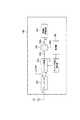
図1は、本実施形態に係る移動端末10の全体概略構成図である。図1に示すように、移動端末10は、本体部11、液晶表示部12及びアンテナ13を備える。(1.1) Schematic configuration of mobile terminal FIG. 1 is an overall schematic configuration diagram of a
本体部11と液晶表示部12とは、回動可能に連結される。すなわち、移動端末10は、当該連結部分を中心として折り畳んだり、広げたりすることができる。 The
また、本体部11の内部には、無線基地局(不図示)との無線通信を実行する無線通信部100が設けられる。 In addition, a
(1.2)無線通信部の機能ブロック構成
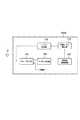
図2は、移動端末10(本体部11)の内部に設けられる無線通信部100の機能ブロック構成図である。図2に示すように、無線通信部100は、デュープレクサ101、マッチング回路103、サーキュレータ105、高周波増幅回路107、検波器109及びマッチング回路制御部111を備える。(1.2) Functional Block Configuration of Radio Communication Unit FIG. 2 is a functional block configuration diagram of the
デュープレクサ101には、アンテナ13が接続される。デュープレクサ101は、無線基地局に向けて送信される上り信号と、無線基地局から送信された下り信号とを分離する。アンテナ13を介して受信した下り信号は、マッチング回路103に出力される。 An
マッチング回路103は、アンテナ13のインピーダンスZ1と、高周波増幅回路107のインピーダンスZ2とをマッチング(整合)させる。Matching
特に、本実施形態では、マッチング回路103は、移動端末10の使用状態によってアンテナ13のインピーダンスZ1(特性インピーダンス)が変化した場合、マッチング回路制御部111からの制御に基づいて、アンテナ13のインピーダンスZ1を変化させる。移動端末10の使用状態によってアンテナ13の特性インピーダンスが変化する場合としては、例えば、移動端末10の近傍に人間が居る場合と、金属製の物体がある場合が挙げられる。また、移動端末10が折り畳まれている状態から広げられている状態とでもアンテナ13の特性インピーダンスが変化する。In particular, in the present embodiment, when the impedance Z1 (characteristic impedance) of the
サーキュレータ105は、マッチング回路103、高周波増幅回路107及び検波器109と接続される。具体的には、サーキュレータ105は、端子1051(第1端子)、端子1052(第2端子)及び端子1053(第3端子)を有する。端子1052は、端子1051の後段に位置する。端子1053は、端子1052の後段に位置する。The
マッチング回路103は、端子1051に接続される。高周波増幅回路107は、端子1052に接続される。また、検波器109は、端子1053に接続される。
サーキュレータ105は、端子1051から端子1052への方向にのみ、アンテナ13側から出力された高周波信号を通過させる。また、サーキュレータ105は、端子1052から端子1053への方向にのみ当該高周波信号を通過させる。The
高周波増幅回路107は、アンテナ13から出力された高周波信号を増幅する。具体的には、アンテナ13から出力された高周波信号は、デュープレクサ101、マッチング回路103及びサーキュレータ105を介して高周波増幅回路107に入力される。 The high
検波器109は、サーキュレータ105の端子1053に出力された高周波信号の有無を検出する。具体的には、検波器109は、サーキュレータ105の端子1053に出力された電流を検出する。
検波器109は、当該高周波信号を検出した場合、当該高周波信号を検出したことをマッチング回路制御部111に出力する。 When detecting the high-frequency signal, the
上述した構成を有する無線通信部100では、アンテナ13(及びデュープレクサ101)のインピーダンスZ1と、高周波増幅回路107のインピーダンスZ2とがマッチングしていない場合、アンテナ13から出力された高周波信号の一部は、高周波増幅回路107に入力されず、高周波増幅回路107からの反射波となってアンテナ13の方向に戻る。つまり、インピーダンスZ1とインピーダンスZ2との不整合に伴って高周波増幅回路107からの反射波が発生する。In the
一方、マッチング回路103が最適な状態で動作している場合、つまり、インピーダンスZ1とインピーダンスZ2とがマッチングしている場合、高周波増幅回路107からの反射波は発生しない。この場合、検波器109は、端子1053において高周波信号、具体的には、高周波増幅回路107からの反射波を検出することはない。また、高周波増幅回路107からの反射波は、サーキュレータ105の機能によって、端子1052から端子1053への方向にのみ出力される。On the other hand, if the
マッチング回路制御部111は、マッチング回路103を制御する。具体的には、マッチング回路制御部111は、検波器109によって高周波信号(反射波)が検出された場合、マッチング回路103を制御することによってアンテナ13のインピーダンスZ1を変化させる。本実施形態では、マッチング回路制御部111は、検波器109によって高周波信号が検出された場合、アンテナ13のインピーダンスZ1を増大させる。The matching
ここで、検波器109によって高周波信号(反射波)が検出された場合、アンテナ13のインピーダンスZ1が、高周波増幅回路107のインピーダンスZ2よりも小さい否かは、判断できない。本実施形態では、マッチング回路制御部111は、検波器109によって高周波信号(反射波)が検出された場合、インピーダンスZ1がインピーダンスZ2よりも小さいと仮定してインピーダンスZ1を増大させる。なお、アンテナ13のインピーダンスZ1の具体的な制御方法については、後述する。Here, if the high-frequency signal by the detector 109 (reflected wave) is detected, the impedance Z1 of the
(1.3)無線通信部の動作
次に、移動端末10の動作について説明する。具体的には、無線通信部100がアンテナ13のインピーダンスZ1(特性インピーダンス)を制御する動作について説明する。(1.3) Operation of Radio Communication Unit Next, the operation of the
図3は、無線通信部100がアンテナ13のインピーダンスZ1(特性インピーダンス)を制御する動作フローを示す。図3に示すように、ステップS10において、無線通信部100は、サーキュレータ105の端子1053において、高周波信号(反射波)を検出したか否かを判定する。具体的には、無線通信部100は、端子1053において検出電流I0があるか否かを判定する。FIG. 3 shows an operation flow in which the
検出電流I0がある場合(ステップS10のYES)、ステップS20において、無線通信部100は、アンテナ13のインピーダンスZ1(特性インピーダンス)を増大させる。具体的には、マッチング回路103を制御することによって、アンテナ13のインピーダンスZ1を予め規定された値(例えば、1Ω分)増大させる。If the detected current I0 is present (YES in step S10), the
ステップS30において、無線通信部100は、端子1053において検出電流I1があるか否かを判定する。In step S30, the
検出電流I1がある場合(ステップS30のYES)、ステップS40において、無線通信部100は、検出電流I1が検出電流I0以下か否かを判定する。When there is the detection current I1 (YES in step S30), in step S40, the
検出電流I1が検出電流I0以下である場合(ステップS40のYES)、ステップS50において、無線通信部100は、マッチング回路103を制御することによってアンテナ13のインピーダンスZ1を予め規定された値増大させる。If the detected currentI 1 is equal to or less than the detection currentI 0 (YES in step S40), in step S50, the
ステップS60において、無線通信部100は、端子1053において検出電流I2があるか否かを判定する。In step S60, the
検出電流I2がある場合(ステップS60のYES)、ステップS70において、無線通信部100は、無線通信部100は、検出電流I2が検出電流I1以下か否かを判定する。If there is a detected currentI 2 (YES in step S60), in step S70, the
一方、検出電流I0、検出電流I1または検出電流I2がない場合(ステップS10のNO、ステップS30のNOまたはステップS60のNO)、無線通信部100は、アンテナ13(及びデュープレクサ101)のインピーダンスZ1と、高周波増幅回路107のインピーダンスZ2とがマッチングしていると判定する。On the other hand, when there is no detection current I0 , detection current I1 or detection current I2 (NO in
検出電流I2が検出電流I1以下である場合(ステップS70のYES)、ステップS80において、無線通信部100は、マッチング回路103を制御することによってアンテナ13のインピーダンスZ1を予め規定された値増大させる。If the detected currentI 2 is the detected currentI 1 or less (YES in step S70), in step S80, the
検出電流I2が検出電流I1を上回る場合(ステップS70のNO)、ステップS90において、無線通信部100は、マッチング回路103を制御することによってアンテナ13のインピーダンスZ1を予め規定された値減少させる。If the detected currentI 2 exceeds the detection currentI 1 (NO in step S70), in step S90, the
また、検出電流I1が検出電流I0を上回る場合(ステップS40のNO)、ステップS100において、無線通信部100は、マッチング回路103を制御することによってアンテナ13のインピーダンスZ1を予め規定された値減少させる。Further, if the detected currentI 1 exceeds the detection currentI 0 (NO in step S40), in step S100, the
次いで、ステップS110〜S140では、上述したステップS60〜S90と同様の処理が実行される。また、無線通信部100は、端子1053において電流、つまり、反射波が検出されなくなるまで、ステップS40〜S140における処理を繰り返す。Next, in steps S110 to S140, processing similar to that in steps S60 to S90 described above is executed. The
(1.4)作用・効果
移動端末10、具体的には、無線通信部100によれば、アンテナ13のインピーダンスZ1と高周波増幅回路107のインピーダンスZ2とがマッチングしていない場合、高周波増幅回路107からの反射波がサーキュレータ105の端子1053に高周波信号として出力される。すなわち、移動端末10の使用状態に応じてアンテナ13の特性インピーダンスが変化したことを検出することができる。さらに、アンテナ13の特性インピーダンスが変化したことが検出されると、マッチング回路103を制御することによってアンテナ13のインピーダンスZ1を変化させることできる。(1.4) Operation and Effect
つまり、無線通信部100によれば、使用状態に応じて変化するアンテナ13の特性変化を検出し、変化するアンテナ13の特性に適応することによって、無線通信部100の送受信性能の劣化を抑制できる。 That is, according to the
本実施形態では、検波器109によって高周波信号(反射波)が検出された場合、マッチング回路制御部111は、アンテナ13のインピーダンスZ1を増大させる。上述したように、検波器109によって高周波信号が検出された場合、アンテナ13のインピーダンスZ1が、高周波増幅回路107のインピーダンスZ2よりも小さい否かは、判断できない。In the present embodiment, when the high-frequency signal (reflected wave) is detected by the
そこで、本実施形態では、マッチング回路制御部111は、当該高周波信号が検出された場合、インピーダンスZ1がインピーダンスZ2よりも小さいと仮定してインピーダンスZ1を増大させる。さらに、インピーダンスZ1を増大させた後における当該高周波信号のレベル、具体的には、検波器109による検出電流(検出電流I1,検出電流I2)と、増大前における検出電流(検出電流I0,検出電流I1)とを比較することによって、インピーダンスZ1を増大させるか減少させるかが決定される。Therefore, in the present embodiment, the matching
すなわち、無線通信部100によれば、検波器109と、マッチング回路103を制御するマッチング回路制御部111とによる簡素な構成としつつ、アンテナ13の特性インピーダンスの変化に適応することができる。 That is, according to the
(2)第2実施形態
第2実施形態では、アンテナの共振周波数、つまり、アンテナを介して受信した無線信号の中心周波数のずれに基づいてアンテナの特性インピーダンスの変化を検出する移動端末について説明する。具体的には、(2.1)無線通信部の機能ブロック構成、(2.2)無線通信部の動作及び(2.3)作用・効果について説明する。(2) Second Embodiment In the second embodiment, a mobile terminal that detects a change in antenna characteristic impedance based on a resonance frequency of the antenna, that is, a shift in the center frequency of a radio signal received via the antenna will be described. . Specifically, (2.1) functional block configuration of the wireless communication unit, (2.2) operation of the wireless communication unit, and (2.3) operation / effect will be described.
(2.1)無線通信部の機能ブロック構成
本実施形態でも、第1実施形態に係る移動端末10(図1参照)と同様の形状を有する移動端末が用いられる。本実施形態では、第1実施形態に係る無線通信部100(図2参照)に代えて、無線通信部100Aが設けられる。(2.1) Functional Block Configuration of Radio Communication Unit Also in this embodiment, a mobile terminal having the same shape as the
図4は、無線通信部100Aの機能ブロック構成図である。図2に示すように、無線通信部100Aは、デュープレクサ101、マッチング回路103、高周波増幅回路107、受信レベル測定部113及びアンテナ制御部115を備える。 FIG. 4 is a functional block configuration diagram of the
デュープレクサ101、マッチング回路103及び高周波増幅回路107は、第1実施形態に係る無線通信部100に備えられている当該機能ブロックと同様の機能を有する。なお、マッチング回路103は、高周波増幅回路107と直接接続される。 The
受信レベル測定部113は、高周波増幅回路107に入力された高周波信号の受信レベルを測定する。本実施形態において、受信レベル測定部113は、測定部を構成する。 The reception
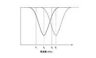
具体的には、図6に示すように、受信レベル測定部113は、アンテナ13の共振周波数を基準とした基準周波数(周波数f0)におけるReceived Signal Code Power(RSCP)を測定する。Specifically, as shown in FIG. 6, the reception
また、受信レベル測定部113は、当該基準周波数から所定周波数離れたオフセット周波数(周波数f1,周波数f2)におけるRSCPを測定する。周波数f2(高オフセット周波数)は、周波数f0よりも高く、周波数f1(低オフセット周波数)は、周波数f0よりも低い。本実施形態では、周波数f0と周波数f2との差、及び周波数f0と周波数f1との差は、それぞれ2.5MHzに設定される。Further, the reception
受信レベル測定部113は、測定したRSCPをアンテナ制御部115に所定の時間間隔で出力する。 Reception
アンテナ制御部115は、アンテナ13の共振周波数を制御する。具体的には、アンテナ制御部115は、受信レベル測定部113によって測定されたオフセット周波数(周波数f1または周波数f2)における受信レベル(RSCP)が、基準周波数(周波数f0)における受信レベルよりも高い場合、アンテナ13を制御することによって、アンテナ13の共振周波数を基準周波数の方向にシフトさせる。The
本実施形態では、アンテナ制御部115は、周波数f2(高オフセット周波数)、及び周波数f1(低オフセット周波数)における受信レベルに基づいて、アンテナ13の共振周波数を基準周波数の方向にシフトさせる。In the present embodiment, the
例えば、図6に示すように、アンテナ13の特性インピーダンスの変化に伴って、アンテナ13の共振周波数、具体的には、アンテナ13を介して受信した無線信号の中心周波数が、周波数f0が周波数F0’に変化した場合、周波数f2における受信レベルが最大となる。アンテナ制御部115は、アンテナ13を介して受信した無線信号の中心周波数が低くなるようにアンテナ13を制御する。なお、アンテナ13の共振周波数の具体的な制御方法については、後述する。For example, as shown in FIG. 6, as the characteristic impedance of the
(2.2)無線通信部の動作
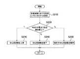
次に、無線通信部100Aがアンテナ13の共振周波数を制御する動作について説明する。図5は、無線通信部100Aがアンテナ13の共振周波数を制御する動作フローを示す。図5に示すように、ステップS210において、無線通信部100Aは、基準周波数(周波数f0)及びオフセット周波数(周波数f1,周波数f2)における受信レベル(RSCP)を測定する。(2.2) Operation of Radio Communication Unit Next, an operation in which the
ステップS220において、無線通信部100Aは、RSCPが最大である周波数を判定する。 In step S220, the
周波数f1のRSCPが最大である場合(ステップS220のf1)、ステップS230において、無線通信部100Aは、アンテナ13を制御し、中心周波数(周波数F0’)を上昇させる。When the RSCP of the frequency f1 is the maximum (f1 in step S220), in step S230, the
周波数f2のRSCPが最大である場合(ステップS220のf2)、ステップS240において、無線通信部100Aは、アンテナ13を制御し、中心周波数(周波数F0’)を低下させる。When the RSCP of the frequency f2 is the maximum (f2 in step S220), in step S240, the
周波数f0のRSCPが最大である場合(ステップS220のf0)、ステップS250において、無線通信部100Aは、現在の中心周波数を維持する。When the RSCP of the frequency f0 is the maximum (f0 in step S220), in step S250, the
無線通信部100Aは、周波数f0のRSCPが最大になるまで、ステップS210〜S250の処理を繰り返す。The
(2.3)作用・効果
無線通信部100Aによれば、アンテナ13の共振周波数を基準とした基準周波数(周波数f0)と、オフセット周波数(周波数f1または周波数f2)とにおける高周波信号のRSCPが受信レベル測定部113によって測定される。(2.3) Action / Effect According to the
このため、移動端末の使用状態に応じたアンテナ13の特性インピーダンスの変化に伴うアンテナ13の共振周波数の変化を検出することができる。また、オフセット周波数における高周波信号のRSCPが、基準周波数におけるRSCPよりも高い場合、アンテナ13を制御することによって、共振周波数が基準周波数の方向にシフトさせられる。 For this reason, it is possible to detect a change in the resonance frequency of the
つまり、無線通信部100Aが設けられた移動端末によれば、使用状態に応じて変化するアンテナ13の特性変化を検出し、変化するアンテナ13の特性に適応することによって送受信性能の劣化を抑制できる。 That is, according to the mobile terminal provided with the
本実施形態では、基準周波数(周波数f0)よりも高い周波数f2、及び基準周波数よりも低い周波数f1における受信レベルが測定される。このため、アンテナ13の共振周波数の変化をより迅速に基準周波数に近付けることができる。 In this embodiment, the reception level at the frequency f2 higher than the reference frequency (frequency f0) and the frequency f1 lower than the reference frequency is measured. For this reason, the change of the resonance frequency of the
(3)その他の実施形態
上述したように、本発明の第1実施形態及び第2実施形態を通じて本発明の内容を開示したが、この開示の一部をなす論述及び図面は、本発明を限定するものであると理解すべきではない。この開示から当業者には様々な代替実施の形態が明らかとなろう。(3) Other Embodiments As described above, the contents of the present invention have been disclosed through the first embodiment and the second embodiment of the present invention. However, the description and the drawings constituting a part of this disclosure limit the present invention. It should not be understood to be. From this disclosure, various alternative embodiments will be apparent to those skilled in the art.
例えば、第1実施形態では、検波器109によって高周波信号が検出された場合、まず、アンテナ13のインピーダンスZ1を増大させていたが、アンテナ13のインピーダンスZ1を減少させてもよい。For example, in the first embodiment, the
第1実施形態では、サーキュレータ105が用いられていたが、サーキュレータ105に代えて、アイソレータを用いても構わない。 Although the
また、第2実施形態では、周波数f1及び周波数f2の複数のオフセット周波数が用いられていたが、オフセット周波数は、何れか一方でも構わない。 In the second embodiment, a plurality of offset frequencies of the frequency f1 and the frequency f2 are used. However, any one of the offset frequencies may be used.
第2実施形態では、受信レベル測定部113は、RSCPを測定したが、必ずしもRSCPでなくてもよく、当該高周波信号の受信レベルを示す値あれば、他の値を用いても構わない。 In the second embodiment, the reception
このように、本発明は、ここでは記載していない様々な実施の形態などを含むことは勿論である。したがって、本発明の技術的範囲は、上述の説明から妥当な特許請求の範囲に係る発明特定事項によってのみ定められるものである。 As described above, the present invention naturally includes various embodiments that are not described herein. Therefore, the technical scope of the present invention is defined only by the invention specifying matters according to the scope of claims reasonable from the above description.
10…移動端末、11…本体部、12…液晶表示部、13…アンテナ、100,100A…無線通信部、101…デュープレクサ、103…マッチング回路、105…サーキュレータ、1051〜1053…端子、107…高周波増幅回路、109…検波器、111…マッチング回路制御部、113…受信レベル測定部、115…アンテナ制御部10 ... mobile terminal, 11 ... main body, 12 ... liquid crystal display unit, 13 ... antenna, 100, 100A ... wireless communication unit, 101 ... duplexer, 103 ... matching circuit, 105 ...circulator 105 1-105 3... terminal, 107 DESCRIPTION OF SYMBOLS ... High frequency amplifier circuit, 109 ... Detector, 111 ... Matching circuit control part, 113 ... Reception level measurement part, 115 ... Antenna control part
Claims (2)
Translated fromJapanese前記アンテナから出力された高周波信号を増幅する高周波増幅回路と、
前記アンテナのインピーダンスと前記高周波増幅回路のインピーダンスとをマッチングさせるマッチング回路と
を備える移動端末であって、
第1端子、前記第1端子の後段に位置する第2端子、及び前記第2端子の後段に位置する第3端子を有し、前記第1端子から前記第2端子への片方向にのみ及び前記第2端子から前記第3端子への片方向にのみ前記高周波信号を通過させるサーキュレータと、
前記高周波信号の有無を検出する検波器と、
前記検波器によって前記高周波信号が検出された場合、前記マッチング回路を制御することによって前記アンテナのインピーダンスを変化させるマッチング回路制御部と
を備え、
前記マッチング回路は、前記第1端子に接続され、
前記高周波増幅回路は、前記第2端子に接続され、
前記検波器は、前記第3端子に接続される移動端末。An antenna,
A high frequency amplifier circuit for amplifying a high frequency signal output from the antenna;
A mobile terminal comprising a matching circuit for matching the impedance of the antenna and the impedance of the high-frequency amplifier circuit,
A first terminal, a second terminal located after the first terminal, and a third terminal located after the second terminal, and only in one direction from the first terminal to the second terminal; A circulator that passes the high-frequency signal only in one direction from the second terminal to the third terminal;
A detector for detecting the presence or absence of the high-frequency signal;
When the high-frequency signal is detected by the detector, a matching circuit control unit that changes the impedance of the antenna by controlling the matching circuit, and
The matching circuit is connected to the first terminal;
The high-frequency amplifier circuit is connected to the second terminal;
The detector is a mobile terminal connected to the third terminal.
Priority Applications (1)
| Application Number | Priority Date | Filing Date | Title |
|---|---|---|---|
| JP2007161687AJP4889578B2 (en) | 2007-06-19 | 2007-06-19 | Mobile terminal |
Applications Claiming Priority (1)
| Application Number | Priority Date | Filing Date | Title |
|---|---|---|---|
| JP2007161687AJP4889578B2 (en) | 2007-06-19 | 2007-06-19 | Mobile terminal |
Related Child Applications (1)
| Application Number | Title | Priority Date | Filing Date |
|---|---|---|---|
| JP2011237483ADivisionJP5400855B2 (en) | 2011-10-28 | 2011-10-28 | Mobile terminal and antenna control method |
Publications (2)
| Publication Number | Publication Date |
|---|---|
| JP2009004902A JP2009004902A (en) | 2009-01-08 |
| JP4889578B2true JP4889578B2 (en) | 2012-03-07 |
Family
ID=40320842
Family Applications (1)
| Application Number | Title | Priority Date | Filing Date |
|---|---|---|---|
| JP2007161687AExpired - Fee RelatedJP4889578B2 (en) | 2007-06-19 | 2007-06-19 | Mobile terminal |
Country Status (1)
| Country | Link |
|---|---|
| JP (1) | JP4889578B2 (en) |
Family Cites Families (7)
| Publication number | Priority date | Publication date | Assignee | Title |
|---|---|---|---|---|
| US5701595A (en)* | 1995-05-04 | 1997-12-23 | Nippondenso Co., Ltd. | Half duplex RF transceiver having low transmit path signal loss |
| JP3332071B2 (en)* | 1998-03-05 | 2002-10-07 | 日本電気株式会社 | Antenna matching adjustment circuit |
| JP3884958B2 (en)* | 1999-10-13 | 2007-02-21 | 株式会社日立製作所 | Communication terminal, in-vehicle communication terminal, and vehicle using the same |
| JP2001211096A (en)* | 2000-01-25 | 2001-08-03 | Toshiba Corp | Mobile terminal device |
| JP4133977B2 (en)* | 2004-09-07 | 2008-08-13 | アルパイン株式会社 | Booster amplifier for radio receiver |
| JP2006287572A (en)* | 2005-03-31 | 2006-10-19 | Fujitsu Ten Ltd | Amplifier system and control method of amplifier system |
| JP4634215B2 (en)* | 2005-05-09 | 2011-02-16 | 株式会社日立国際電気 | Matcher |
- 2007
- 2007-06-19JPJP2007161687Apatent/JP4889578B2/ennot_activeExpired - Fee Related
Also Published As
| Publication number | Publication date |
|---|---|
| JP2009004902A (en) | 2009-01-08 |
Similar Documents
| Publication | Publication Date | Title |
|---|---|---|
| US9755690B2 (en) | Multiband wireless communication method and multiband wireless communication apparatus | |
| US9048536B2 (en) | Mobile communication device and impedance matching method thereof | |
| JP5858015B2 (en) | Vehicle communication device | |
| US7492812B2 (en) | RFID transceiver device | |
| US20100222012A1 (en) | Wireless communication apparatus and method | |
| EP2139111B1 (en) | Radio wave receiving apparatus | |
| TWI591892B (en) | Wireless communication apparatus and method for improving specific absorption ratio thereof | |
| KR20190040050A (en) | Communication method and mobile terminal | |
| KR101503866B1 (en) | Transmitting apparatus and method for improving channel deviation in a mobile communication terminal | |
| JP5400855B2 (en) | Mobile terminal and antenna control method | |
| CN1489830A (en) | TDMA transceiver and receiving automatic gain control method thereof | |
| JP4889578B2 (en) | Mobile terminal | |
| CN117044115A (en) | Radio circuit with loop path all-pass filter | |
| US20050272457A1 (en) | Handling transmissions via a radio link | |
| JP2008252418A (en) | Portable radio terminal, power control method and power control program | |
| US20120282865A1 (en) | Signal transceiving module | |
| US20220263227A1 (en) | Electronic device | |
| US8922450B2 (en) | Signal converting circuit capable of reducing/avoiding signal leakage and related signal converting method | |
| JP2009272907A (en) | Radio communication terminal | |
| US10008991B2 (en) | Communication device | |
| JP6507758B2 (en) | Communication module and communication control method | |
| JP2010161575A (en) | Transceiver | |
| JP2016086371A (en) | Transmitter receiver | |
| KR20070033509A (en) | Apparatus and method for reducing hand effect of a terminal having a built-in antenna | |
| JP2010109546A (en) | Radio equipment and control method therefor |
Legal Events
| Date | Code | Title | Description |
|---|---|---|---|
| A621 | Written request for application examination | Free format text:JAPANESE INTERMEDIATE CODE: A621 Effective date:20100225 | |
| A977 | Report on retrieval | Free format text:JAPANESE INTERMEDIATE CODE: A971007 Effective date:20110812 | |
| A131 | Notification of reasons for refusal | Free format text:JAPANESE INTERMEDIATE CODE: A131 Effective date:20110830 | |
| A521 | Written amendment | Free format text:JAPANESE INTERMEDIATE CODE: A523 Effective date:20111028 | |
| TRDD | Decision of grant or rejection written | ||
| A01 | Written decision to grant a patent or to grant a registration (utility model) | Free format text:JAPANESE INTERMEDIATE CODE: A01 Effective date:20111122 | |
| A01 | Written decision to grant a patent or to grant a registration (utility model) | Free format text:JAPANESE INTERMEDIATE CODE: A01 | |
| A61 | First payment of annual fees (during grant procedure) | Free format text:JAPANESE INTERMEDIATE CODE: A61 Effective date:20111213 | |
| R150 | Certificate of patent or registration of utility model | Ref document number:4889578 Country of ref document:JP Free format text:JAPANESE INTERMEDIATE CODE: R150 Free format text:JAPANESE INTERMEDIATE CODE: R150 | |
| FPAY | Renewal fee payment (event date is renewal date of database) | Free format text:PAYMENT UNTIL: 20141222 Year of fee payment:3 | |
| R250 | Receipt of annual fees | Free format text:JAPANESE INTERMEDIATE CODE: R250 | |
| R250 | Receipt of annual fees | Free format text:JAPANESE INTERMEDIATE CODE: R250 | |
| R250 | Receipt of annual fees | Free format text:JAPANESE INTERMEDIATE CODE: R250 | |
| R250 | Receipt of annual fees | Free format text:JAPANESE INTERMEDIATE CODE: R250 | |
| LAPS | Cancellation because of no payment of annual fees |