JP4886031B2 - Cooking package - Google Patents
Cooking packageDownload PDFInfo
- Publication number
- JP4886031B2 JP4886031B2JP2009512078AJP2009512078AJP4886031B2JP 4886031 B2JP4886031 B2JP 4886031B2JP 2009512078 AJP2009512078 AJP 2009512078AJP 2009512078 AJP2009512078 AJP 2009512078AJP 4886031 B2JP4886031 B2JP 4886031B2
- Authority
- JP
- Japan
- Prior art keywords
- tray
- food
- package
- flap
- blank
- Prior art date
- Legal status (The legal status is an assumption and is not a legal conclusion. Google has not performed a legal analysis and makes no representation as to the accuracy of the status listed.)
- Expired - Fee Related
Links
- 238000010411cookingMethods0.000titleclaimsdescription16
- 235000013305foodNutrition0.000claimsdescription136
- 239000000463materialSubstances0.000claimsdescription73
- 230000003993interactionEffects0.000claimsdescription43
- 230000002452interceptive effectEffects0.000claimsdescription41
- 238000010438heat treatmentMethods0.000claimsdescription27
- 238000000034methodMethods0.000claimsdescription18
- 239000011087paperboardSubstances0.000claimsdescription11
- 239000010408filmSubstances0.000description41
- 239000010410layerSubstances0.000description34
- 230000004888barrier functionEffects0.000description26
- 239000000758substrateSubstances0.000description24
- 210000004027cellAnatomy0.000description14
- 239000000853adhesiveSubstances0.000description13
- 230000001070adhesive effectEffects0.000description13
- 229910052751metalInorganic materials0.000description13
- 239000002184metalSubstances0.000description13
- 239000000123paperSubstances0.000description11
- 239000011810insulating materialSubstances0.000description10
- 229920006254polymer filmPolymers0.000description8
- BQCADISMDOOEFD-UHFFFAOYSA-NSilverChemical compound[Ag]BQCADISMDOOEFD-UHFFFAOYSA-N0.000description7
- 229910052709silverInorganic materials0.000description7
- 239000004332silverSubstances0.000description7
- 229920002292Nylon 6Polymers0.000description6
- 229910045601alloyInorganic materials0.000description6
- 239000000956alloySubstances0.000description6
- 238000000576coating methodMethods0.000description6
- 230000000694effectsEffects0.000description6
- 230000004048modificationEffects0.000description6
- 238000012986modificationMethods0.000description6
- 238000004806packaging method and processMethods0.000description6
- 229920006255plastic filmPolymers0.000description6
- 239000002985plastic filmSubstances0.000description6
- 229920000139polyethylene terephthalatePolymers0.000description6
- 239000005020polyethylene terephthalateSubstances0.000description6
- 229910052782aluminiumInorganic materials0.000description5
- XAGFODPZIPBFFR-UHFFFAOYSA-NaluminiumChemical compound[Al]XAGFODPZIPBFFR-UHFFFAOYSA-N0.000description5
- 239000011888foilSubstances0.000description5
- 229910044991metal oxideInorganic materials0.000description5
- 150000004706metal oxidesChemical class0.000description5
- -1polyethylene terephthalatePolymers0.000description5
- XLYOFNOQVPJJNP-UHFFFAOYSA-NwaterChemical compoundOXLYOFNOQVPJJNP-UHFFFAOYSA-N0.000description5
- 229920002799BoPETPolymers0.000description4
- XEEYBQQBJWHFJM-UHFFFAOYSA-NIronChemical compound[Fe]XEEYBQQBJWHFJM-UHFFFAOYSA-N0.000description4
- VYPSYNLAJGMNEJ-UHFFFAOYSA-NSilicium dioxideChemical compoundO=[Si]=OVYPSYNLAJGMNEJ-UHFFFAOYSA-N0.000description4
- QVGXLLKOCUKJST-UHFFFAOYSA-Natomic oxygenChemical compound[O]QVGXLLKOCUKJST-UHFFFAOYSA-N0.000description4
- 239000011248coating agentSubstances0.000description4
- 239000004715ethylene vinyl alcoholSubstances0.000description4
- 238000009413insulationMethods0.000description4
- 150000002739metalsChemical class0.000description4
- 229910052760oxygenInorganic materials0.000description4
- 239000001301oxygenSubstances0.000description4
- 229920000642polymerPolymers0.000description4
- 229910052814silicon oxideInorganic materials0.000description4
- 230000003313weakening effectEffects0.000description4
- 229920000219Ethylene vinyl alcoholPolymers0.000description3
- 229920002302Nylon 6,6Polymers0.000description3
- 239000012790adhesive layerSubstances0.000description3
- 230000008901benefitEffects0.000description3
- 230000005540biological transmissionEffects0.000description3
- 239000004927claySubstances0.000description3
- 230000006870functionEffects0.000description3
- RZXDTJIXPSCHCI-UHFFFAOYSA-Nhexa-1,5-diene-2,5-diolChemical compoundOC(=C)CCC(O)=CRZXDTJIXPSCHCI-UHFFFAOYSA-N0.000description3
- RYGMFSIKBFXOCR-UHFFFAOYSA-NCopperChemical compound[Cu]RYGMFSIKBFXOCR-UHFFFAOYSA-N0.000description2
- PXHVJJICTQNCMI-UHFFFAOYSA-NNickelChemical compound[Ni]PXHVJJICTQNCMI-UHFFFAOYSA-N0.000description2
- 229920001328Polyvinylidene chloridePolymers0.000description2
- 230000002745absorbentEffects0.000description2
- 239000002250absorbentSubstances0.000description2
- 239000011149active materialSubstances0.000description2
- 238000005452bendingMethods0.000description2
- 229920002678cellulosePolymers0.000description2
- 239000001913celluloseSubstances0.000description2
- 230000008859changeEffects0.000description2
- 229910052802copperInorganic materials0.000description2
- 239000010949copperSubstances0.000description2
- 239000007888film coatingSubstances0.000description2
- 238000009501film coatingMethods0.000description2
- 239000007789gasSubstances0.000description2
- 239000004615ingredientSubstances0.000description2
- 210000003168insulating cellAnatomy0.000description2
- 239000012774insulation materialSubstances0.000description2
- 238000003475laminationMethods0.000description2
- 239000005022packaging materialSubstances0.000description2
- 239000002861polymer materialSubstances0.000description2
- 239000005033polyvinylidene chlorideSubstances0.000description2
- 239000004065semiconductorSubstances0.000description2
- 150000004760silicatesChemical class0.000description2
- 229910001220stainless steelInorganic materials0.000description2
- 239000010935stainless steelSubstances0.000description2
- 239000002966varnishSubstances0.000description2
- 238000009423ventilationMethods0.000description2
- 238000003855Adhesive LaminationMethods0.000description1
- 241000538568Brachydeuterus auritusSpecies0.000description1
- 229920000298CellophanePolymers0.000description1
- VYZAMTAEIAYCRO-UHFFFAOYSA-NChromiumChemical compound[Cr]VYZAMTAEIAYCRO-UHFFFAOYSA-N0.000description1
- FYYHWMGAXLPEAU-UHFFFAOYSA-NMagnesiumChemical compound[Mg]FYYHWMGAXLPEAU-UHFFFAOYSA-N0.000description1
- 241000422980MariettaSpecies0.000description1
- 229910001182Mo alloyInorganic materials0.000description1
- 239000004677NylonSubstances0.000description1
- 239000004952PolyamideSubstances0.000description1
- 239000004642PolyimideSubstances0.000description1
- ATJFFYVFTNAWJD-UHFFFAOYSA-NTinChemical compound[Sn]ATJFFYVFTNAWJD-UHFFFAOYSA-N0.000description1
- RTAQQCXQSZGOHL-UHFFFAOYSA-NTitaniumChemical compound[Ti]RTAQQCXQSZGOHL-UHFFFAOYSA-N0.000description1
- 238000005273aerationMethods0.000description1
- 229920005603alternating copolymerPolymers0.000description1
- 230000009286beneficial effectEffects0.000description1
- 239000011230binding agentSubstances0.000description1
- 235000021450burritoNutrition0.000description1
- 239000011111cardboardSubstances0.000description1
- 229910052804chromiumInorganic materials0.000description1
- 239000011651chromiumSubstances0.000description1
- OGSYQYXYGXIQFH-UHFFFAOYSA-Nchromium molybdenum nickelChemical compound[Cr].[Ni].[Mo]OGSYQYXYGXIQFH-UHFFFAOYSA-N0.000description1
- 239000003086colorantSubstances0.000description1
- 239000004020conductorSubstances0.000description1
- 229920001577copolymerPolymers0.000description1
- 230000008878couplingEffects0.000description1
- 238000010168coupling processMethods0.000description1
- 238000005859coupling reactionMethods0.000description1
- 239000013078crystalSubstances0.000description1
- 230000007547defectEffects0.000description1
- 238000005137deposition processMethods0.000description1
- 238000001035dryingMethods0.000description1
- 230000005672electromagnetic fieldEffects0.000description1
- 230000008020evaporationEffects0.000description1
- 238000001704evaporationMethods0.000description1
- 239000000835fiberSubstances0.000description1
- 229920002313fluoropolymerPolymers0.000description1
- 239000004811fluoropolymerSubstances0.000description1
- 239000012634fragmentSubstances0.000description1
- 229920001519homopolymerPolymers0.000description1
- 229910001026inconelInorganic materials0.000description1
- AMGQUBHHOARCQH-UHFFFAOYSA-Nindium;oxotinChemical compound[In].[Sn]=OAMGQUBHHOARCQH-UHFFFAOYSA-N0.000description1
- 229910052742ironInorganic materials0.000description1
- UQSXHKLRYXJYBZ-UHFFFAOYSA-Niron oxideInorganic materials[Fe]=OUQSXHKLRYXJYBZ-UHFFFAOYSA-N0.000description1
- 230000001788irregularEffects0.000description1
- 239000002655kraft paperSubstances0.000description1
- 229910052749magnesiumInorganic materials0.000description1
- 239000011777magnesiumSubstances0.000description1
- 239000011159matrix materialSubstances0.000description1
- 230000007246mechanismEffects0.000description1
- 238000001465metallisationMethods0.000description1
- 239000000203mixtureSubstances0.000description1
- 229910052759nickelInorganic materials0.000description1
- 229910052758niobiumInorganic materials0.000description1
- 239000010955niobiumSubstances0.000description1
- GUCVJGMIXFAOAE-UHFFFAOYSA-Nniobium atomChemical compound[Nb]GUCVJGMIXFAOAE-UHFFFAOYSA-N0.000description1
- 229920001778nylonPolymers0.000description1
- 238000013021overheatingMethods0.000description1
- 238000012536packaging technologyMethods0.000description1
- 229920001643poly(ether ketone)Polymers0.000description1
- 229920002492poly(sulfone)Polymers0.000description1
- 229920002647polyamidePolymers0.000description1
- 229920000728polyesterPolymers0.000description1
- 229920006267polyester filmPolymers0.000description1
- 229920001721polyimidePolymers0.000description1
- 229920000098polyolefinPolymers0.000description1
- 238000002360preparation methodMethods0.000description1
- 238000007639printingMethods0.000description1
- 230000008569processEffects0.000description1
- 238000012545processingMethods0.000description1
- 230000005855radiationEffects0.000description1
- 229920005604random copolymerPolymers0.000description1
- 239000002994raw materialSubstances0.000description1
- 238000004544sputter depositionMethods0.000description1
- 229920001897terpolymerPolymers0.000description1
- 239000010409thin filmSubstances0.000description1
- 229910052718tinInorganic materials0.000description1
- 239000011135tinSubstances0.000description1
- 229910001887tin oxideInorganic materials0.000description1
- QHGNHLZPVBIIPX-UHFFFAOYSA-Ntin(ii) oxideChemical class[Sn]=OQHGNHLZPVBIIPX-UHFFFAOYSA-N0.000description1
- 239000010936titaniumSubstances0.000description1
- 229910052719titaniumInorganic materials0.000description1
- 238000012546transferMethods0.000description1
- WFKWXMTUELFFGS-UHFFFAOYSA-NtungstenChemical compound[W]WFKWXMTUELFFGS-UHFFFAOYSA-N0.000description1
- 229910052721tungstenInorganic materials0.000description1
- 239000010937tungstenSubstances0.000description1
- 230000007306turnoverEffects0.000description1
- 230000000007visual effectEffects0.000description1
Images


Classifications
- B—PERFORMING OPERATIONS; TRANSPORTING
- B65—CONVEYING; PACKING; STORING; HANDLING THIN OR FILAMENTARY MATERIAL
- B65D—CONTAINERS FOR STORAGE OR TRANSPORT OF ARTICLES OR MATERIALS, e.g. BAGS, BARRELS, BOTTLES, BOXES, CANS, CARTONS, CRATES, DRUMS, JARS, TANKS, HOPPERS, FORWARDING CONTAINERS; ACCESSORIES, CLOSURES, OR FITTINGS THEREFOR; PACKAGING ELEMENTS; PACKAGES
- B65D81/00—Containers, packaging elements, or packages, for contents presenting particular transport or storage problems, or adapted to be used for non-packaging purposes after removal of contents
- B65D81/34—Containers, packaging elements, or packages, for contents presenting particular transport or storage problems, or adapted to be used for non-packaging purposes after removal of contents for packaging foodstuffs or other articles intended to be cooked or heated within the package
- B65D81/3446—Containers, packaging elements, or packages, for contents presenting particular transport or storage problems, or adapted to be used for non-packaging purposes after removal of contents for packaging foodstuffs or other articles intended to be cooked or heated within the package specially adapted to be heated by microwaves
- B65D81/3453—Rigid containers, e.g. trays, bottles, boxes, cups
- B—PERFORMING OPERATIONS; TRANSPORTING
- B65—CONVEYING; PACKING; STORING; HANDLING THIN OR FILAMENTARY MATERIAL
- B65D—CONTAINERS FOR STORAGE OR TRANSPORT OF ARTICLES OR MATERIALS, e.g. BAGS, BARRELS, BOTTLES, BOXES, CANS, CARTONS, CRATES, DRUMS, JARS, TANKS, HOPPERS, FORWARDING CONTAINERS; ACCESSORIES, CLOSURES, OR FITTINGS THEREFOR; PACKAGING ELEMENTS; PACKAGES
- B65D2581/00—Containers, packaging elements, or packages, for contents presenting particular transport or storage problems, or adapted to be used for non-packaging purposes after removal of contents
- B65D2581/34—Containers, packaging elements, or packages, for contents presenting particular transport or storage problems, or adapted to be used for non-packaging purposes after removal of contents for packaging foodstuffs or other articles intended to be cooked or heated within
- B65D2581/3437—Containers, packaging elements, or packages, for contents presenting particular transport or storage problems, or adapted to be used for non-packaging purposes after removal of contents for packaging foodstuffs or other articles intended to be cooked or heated within specially adapted to be heated by microwaves
- B65D2581/3439—Means for affecting the heating or cooking properties
- B65D2581/344—Geometry or shape factors influencing the microwave heating properties
- B—PERFORMING OPERATIONS; TRANSPORTING
- B65—CONVEYING; PACKING; STORING; HANDLING THIN OR FILAMENTARY MATERIAL
- B65D—CONTAINERS FOR STORAGE OR TRANSPORT OF ARTICLES OR MATERIALS, e.g. BAGS, BARRELS, BOTTLES, BOXES, CANS, CARTONS, CRATES, DRUMS, JARS, TANKS, HOPPERS, FORWARDING CONTAINERS; ACCESSORIES, CLOSURES, OR FITTINGS THEREFOR; PACKAGING ELEMENTS; PACKAGES
- B65D2581/00—Containers, packaging elements, or packages, for contents presenting particular transport or storage problems, or adapted to be used for non-packaging purposes after removal of contents
- B65D2581/34—Containers, packaging elements, or packages, for contents presenting particular transport or storage problems, or adapted to be used for non-packaging purposes after removal of contents for packaging foodstuffs or other articles intended to be cooked or heated within
- B65D2581/3437—Containers, packaging elements, or packages, for contents presenting particular transport or storage problems, or adapted to be used for non-packaging purposes after removal of contents for packaging foodstuffs or other articles intended to be cooked or heated within specially adapted to be heated by microwaves
- B65D2581/3486—Dielectric characteristics of microwave reactive packaging
- B65D2581/3489—Microwave reflector, i.e. microwave shield
- B65D2581/349—Microwave reflector, i.e. microwave shield attached to the lid
- B—PERFORMING OPERATIONS; TRANSPORTING
- B65—CONVEYING; PACKING; STORING; HANDLING THIN OR FILAMENTARY MATERIAL
- B65D—CONTAINERS FOR STORAGE OR TRANSPORT OF ARTICLES OR MATERIALS, e.g. BAGS, BARRELS, BOTTLES, BOXES, CANS, CARTONS, CRATES, DRUMS, JARS, TANKS, HOPPERS, FORWARDING CONTAINERS; ACCESSORIES, CLOSURES, OR FITTINGS THEREFOR; PACKAGING ELEMENTS; PACKAGES
- B65D2581/00—Containers, packaging elements, or packages, for contents presenting particular transport or storage problems, or adapted to be used for non-packaging purposes after removal of contents
- B65D2581/34—Containers, packaging elements, or packages, for contents presenting particular transport or storage problems, or adapted to be used for non-packaging purposes after removal of contents for packaging foodstuffs or other articles intended to be cooked or heated within
- B65D2581/3437—Containers, packaging elements, or packages, for contents presenting particular transport or storage problems, or adapted to be used for non-packaging purposes after removal of contents for packaging foodstuffs or other articles intended to be cooked or heated within specially adapted to be heated by microwaves
- B65D2581/3486—Dielectric characteristics of microwave reactive packaging
- B65D2581/3494—Microwave susceptor
- B65D2581/3495—Microwave susceptor attached to the lid
Landscapes
- Engineering & Computer Science (AREA)
- Life Sciences & Earth Sciences (AREA)
- Food Science & Technology (AREA)
- Mechanical Engineering (AREA)
- Package Specialized In Special Use (AREA)
- Cookers (AREA)
- Packages (AREA)
- Cartons (AREA)
Description
Translated fromJapanese本願は、2006年5月19日付申請の米国仮特許出願第60/801,968号に対する利益を主張する。上記参照の仮特許出願の全ての内容は、ここに参照されることで援用される。 This application claims the benefit of US Provisional Patent Application No. 60 / 801,968, filed May 19, 2006. The entire contents of the above-referenced provisional patent applications are incorporated herein by reference.
本発明は食品の調理の分野に関連し、特に、電子レンジで食品を調理するために使われ得る素材および構造体に関連する。 The present invention relates to the field of food preparation, and in particular to materials and structures that can be used to cook food in a microwave oven.
電子レンジは通常、素早く効果的に食品を調理するために使用される。電子レンジの調理能力を最適化するために、食品へのマイクロ波の相互作用を妨げ、強め、導き、あるいは影響を与えるために、様々な食品パッケージ配置が開発されてきた。 Microwave ovens are usually used to cook food quickly and effectively. In order to optimize the cooking ability of microwave ovens, various food package arrangements have been developed to prevent, strengthen, direct or influence microwave interactions with food.
食品の外側に焦げ目をつけたい場合、またはカリカリにしたい場合、食品は、サセプタを含む容器の中に配置される。サセプタは通常、マイクロ波エネルギーを様々な比率で吸収、反射、および伝達する、金属のような、マイクロ波エネルギー相互作用素材を含む。焦げ目をつける表面はサセプタに近接して配置される。サセプタはマイクロ波エネルギーを吸収し、それによって高温になり、表面に焦げ目をつけカリカリにするのを促進するために、食品に熱を伝える。さらに、マイクロ波エネルギーの一部は、通常食品の内部に伝達される。 If one wants to scorch or crunchy outside the food, the food is placed in a container containing the susceptor. Susceptors typically include microwave energy interactive materials, such as metals, that absorb, reflect, and transmit microwave energy in various ratios. The scoring surface is placed close to the susceptor. The susceptor absorbs microwave energy and thereby conducts heat to the food to promote high temperatures, scorching and crunching the surface. In addition, some of the microwave energy is usually transmitted inside the food.
多数のサセプタの構造、形状およびサイズは、当該技術分野で周知である。サセプタの配置、マイクロ波エネルギーの照射時間、どの程度焦げ目をつけカリカリにしたいか、および他の要因によって、サセプタは食品と密着するか、または近接して接触し得る。よって、サセプタを含む素材またはパッケージは、従来のフライ、ベーキング、またはグリルと同様の方法で食品を調理したり、食品の表面に焦げ目をつけたり、カリカリにしたりするために使用され得る。 Numerous susceptor structures, shapes, and sizes are well known in the art. Depending on the placement of the susceptor, the duration of the microwave energy exposure, how much charring and crunchiness is desired, and other factors, the susceptor may be in close contact with or in close contact with the food. Thus, a material or package that includes a susceptor can be used to cook food in a manner similar to conventional frying, baking, or grilling, to scorch or crunch the surface of food.
サセプタを利用し得る、ある特定の食品パッケージ配置は、パッケージ素材の層の間に形成された閉塞セルに関係する。マイクロ波エネルギーの照射により、セルは膨張し、外部環境からパッケージに対して、パッケージ内の食品を熱的に絶縁する膨張セルを形成する。膨張可能なセルを備えるマイクロ波パッケージ素材の一例は、同時係属の公開PCT出願PCT/US03/03779、名称「Insulating Microwave Interactive Packaging」で説明されおり、その開示全ては参照することにより本明細書に組み込まれる。 One particular food packaging arrangement that can utilize a susceptor involves a closed cell formed between layers of packaging material. Upon irradiation with microwave energy, the cell expands to form an expanded cell that thermally insulates food in the package from the external environment to the package. An example of a microwave packaging material with an inflatable cell is described in co-pending published PCT application PCT / US03 / 03797, entitled “Insulating Microwave Interactive Packaging”, the entire disclosure of which is hereby incorporated by reference. Incorporated.
これまでの進歩にも関わらず、マイクロ波調理の多数の課題が残っている。例えば、多くの既存のパッケージは形状が一定で、食品の表面に焦げ目をつけたりカリカリにしたりするために、食品に十分近い位置にある調理面を提供しない。よって、改良されたマイクロ波エネルギー相互作用パッケージの必要性が残っている。 Despite progress so far, many challenges remain in microwave cooking. For example, many existing packages are uniform in shape and do not provide a cooking surface that is sufficiently close to the food to burn or crunch the surface of the food. Thus, there remains a need for improved microwave energy interaction packages.
[発明の概要]
概して、本発明の一態様は、電子レンジで食品を加熱するためのパッケージを対象とする。パッケージは、食品を保持するためのトレイと、トレイおよび食品を少なくとも部分的に覆うためのフレキシブルカバーとを備える。カバーはマイクロ波相互作用素材を備える。[Summary of Invention]
In general, one aspect of the invention is directed to a package for heating food in a microwave oven. The package includes a tray for holding food and a flexible cover for at least partially covering the tray and the food. The cover comprises a microwave interactive material.
別の態様では、本発明は概して形状のある食品のためのパッケージを対象とする。パッケージは、食品を保持するためのトレイと、トレイや食品を少なくとも部分的に覆うフレキシブルカバーとを備える。フレキシブルカバーが食品の形状に少なくとも部分的に一致するために適合するように、フレキシブルカバーは、互いに実質的に平行である複数の折り線を備える。 In another aspect, the present invention is directed to a package for a generally shaped food product. The package includes a tray for holding food and a flexible cover that at least partially covers the tray and the food. The flexible cover comprises a plurality of fold lines that are substantially parallel to each other so that the flexible cover is adapted to at least partially conform to the shape of the food product.
別の態様では、本発明は、概して、食品を保持したり加熱したりするためのパッケージを形成するためのブランクに関する。ブランクは、中央パネルと、ブランクがパッケージに形成される際にトレイを形成するために、中央パネルに相対的に位置するように、中央パネルに折り曲げ可能に取り付けられた複数のサイドパネルとを備える複数のトレイパネルを備える。フレキシブルフラップは、中央パネルおよび複数のパネルのうちの少なくとも1つに折り曲げ可能に取り付けられている。フレキシブルフラップが、複数の折り線のうちの折り線によって少なくともそれぞれ部分的に画定される、複数の独立して可動な部分を有するように、フレキシブルフラップは、互いに実質的に平行である複数の折り線を有する。複数の折り線は少なくとも3本の折り線を含み、複数の独立して可動な部分は、少なくとも3つの独立して可動な部分を含む。 In another aspect, the invention generally relates to a blank for forming a package for holding and heating food. The blank comprises a central panel and a plurality of side panels foldably attached to the central panel so as to be positioned relative to the central panel to form a tray when the blank is formed into a package. A plurality of tray panels are provided. The flexible flap is foldably attached to at least one of the center panel and the plurality of panels. The flexible flap includes a plurality of folds that are substantially parallel to each other such that the flexible flap has a plurality of independently movable portions that are each at least partially defined by the fold lines of the plurality of fold lines. With lines. The plurality of fold lines includes at least three fold lines, and the plurality of independently movable portions includes at least three independently movable portions.
別の態様では、本発明は概して、トレイを形成するトレイブランクと、トレイを少なくとも部分的に覆うカバーを形成するカバーブランクとの組み合わせ体を対象とする。トレイブランクは、中央パネルと、中央パネルに折り曲げ可能に取り付けられている複数のサイドパネルとを備える。カバーブランクは、離間した横方向の折り線と、横方向の折り線によって少なくとも部分的に画定される、ブランクの独立して可動な部分とを備える。 In another aspect, the present invention is generally directed to a combination of a tray blank that forms a tray and a cover blank that forms a cover that at least partially covers the tray. The tray blank includes a central panel and a plurality of side panels that are foldably attached to the central panel. The cover blank includes spaced lateral fold lines and an independently movable portion of the blank that is at least partially defined by the lateral fold lines.
別の態様では、本発明は概して、食品を調理する方法を対象とする。該方法は、トレイと、フレキシブルカバーとを備えるパッケージを設けるステップを含む。食品はトレイ内に配置され、カバーで少なくとも部分的に覆われる。食品を少なくとも部分的に覆うステップは、カバーが食品の形状に少なくとも部分的に一致するように、カバーを折り曲げるステップを含む。該方法は、電子レンジで食品を加熱するステップをさらに含む。 In another aspect, the present invention is generally directed to a method of cooking a food product. The method includes providing a package comprising a tray and a flexible cover. The food is placed in the tray and is at least partially covered with a cover. At least partially covering the food product includes folding the cover so that the cover at least partially matches the shape of the food product. The method further includes heating the food in a microwave oven.
別の態様では、本発明は概して、電子レンジで食品を加熱するためのパッケージを対象とする。パッケージは、トレイと、トレイを少なくとも部分的に覆うフレキシブルカバーとを備える。カバーはマイクロ波相互作用素材を備える。 In another aspect, the present invention is generally directed to a package for heating food in a microwave oven. The package includes a tray and a flexible cover that at least partially covers the tray. The cover comprises a microwave interactive material.
別の態様では、本発明は、概して、食品を保持および加熱するためのパッケージを形成するためのブランクを対象とする。ブランクは、ブランクをパッケージに形成する際に、トレイを形成するための複数のトレイパネルを備える。フレキシブルフラップは、トレイパネルの少なくとも1つに折り曲げ可能に取り付けられており、複数の折り線を有する。フレキシブルフラップは、複数の折り線のうちの折り線によってそれぞれ少なくとも部分的に画定される、複数の独立して可動な部分を有する。 In another aspect, the present invention is generally directed to a blank for forming a package for holding and heating food. The blank includes a plurality of tray panels for forming a tray when the blank is formed into a package. The flexible flap is foldably attached to at least one of the tray panels and has a plurality of fold lines. The flexible flap has a plurality of independently movable portions, each at least partially defined by a fold line of the plurality of fold lines.
当業者は、以下に列挙された図面を参照しながら、以下の実施形態の詳細な説明を読むことによって、上記の利点およびその他の利点、および種々の追加の実施形態の利点を理解するであろう。 Those skilled in the art will appreciate the above and other advantages, as well as the advantages of various additional embodiments, by reading the following detailed description of the embodiments with reference to the drawings listed below. Let's go.
一般的な実施に従い、以下で説明する図面の種々の特徴は、一定の縮尺比で描かれているとは限らない。図面の種々の特徴や要素の寸法は、本発明の実施形態をより明確に示すために、拡大または縮小されている場合がある。 In accordance with common practice, the various features of the drawings described below are not necessarily drawn to scale. The dimensions of the various features and elements of the drawings may be expanded or reduced to more clearly illustrate embodiments of the present invention.
図面中、対応する部分は、対応する参照番号によって示される。 Corresponding parts are designated by corresponding reference numerals in the drawings.
本発明は、概して、食品を調理するための素材およびパッケージの様々な態様、およびそのような素材およびパッケージを作製する方法に関連する。複数の異なる発明、態様、実施、および様々な発明の実施形態を提供しているが、様々な発明、態様、実施、および発明の実施形態間の多数の相互関係、その組み合わせ、修正が本明細書において企図される。 The present invention generally relates to various aspects of ingredients and packages for cooking food, and methods of making such ingredients and packages. While several different inventions, aspects, implementations and various invention embodiments are provided, numerous interrelationships, combinations and modifications between the various inventions, aspects, implementations and invention embodiments are described herein. Contemplated in the book.
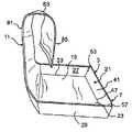
図1は、本発明の第1の実施形態のパッケージ3(図2乃至図4)を形成するために使用される、概して1で示されるブランクの平面図である。パッケージ3は、食品を調理する間、例えばサンドイッチ、カルゾーネ、ターンオーバー、ブリトー、またはその他の食品のような、食品P(図9A)を保持するために使用される。一例において、食品Pが入っているパッケージ3は、食品を加熱および/または調理するために電子レンジ(不図示)内に配置される。図示される実施形態では、パッケージ3は食品を保持するための大きさになっているトレイ7、および食品の周りを少なくとも部分的に包む、折り曲げ可能にトレイに取り付けられている、可撓性のあるフラップまたはフレキシブルフラップ11(広範には「フレキシブルカバー(可撓性のあるカバー)」)を含む。フレキシブルフラップ11および/またはトレイ7の一部は、そこに取り付けられた調理、加熱、焦げ目付けおよび/または遮へいに使用される要素(例えば、限定されないが、サセプタのようなマイクロ波エネルギー相互作用要素15)を有してもよい。尚、マイクロ波エネルギー相互作用要素15(図2)を、パッケージ3から省略できることがわかる。 FIG. 1 is a plan view of a blank, generally indicated at 1, which is used to form a package 3 (FIGS. 2-4) of a first embodiment of the present invention.
ブランク1は、長手軸L1および横軸L2を有する。ブランク1は、パッケージのトレイ7を形成するボトムパネル21を含む。ボトムパネル21は、中央パネル23と、中央パネルの横方向端部にそれぞれ第1および第2パネル27、29とを含む。サイドパネル27、29は長手方向の折り線33、35でそれぞれ中央パネル23に折り曲げ可能に接続している。第3および第4のサイドパネル41、43は、中央パネルの長手方向端部でそれぞれ中央パネル23と折り曲げ可能に接続している。サイドパネル41、43は、横方向の折り線47、49でそれぞれ中央パネル23に折り曲げ可能に接続している。図示される実施形態では、ボトムパネル21は、横方向の折り線49、47に沿ってそれぞれ第1のサイドパネル27に折り曲げ可能に取り付けられている2つのコーナーパネル51、53と、横方向の折り線49、47に沿ってそれぞれ第2のサイドパネル29に折り曲げ可能に取り付けられている2つのコーナーパネル55、57とを含む。コーナーパネル51、53、55、57は、それぞれスリット58等によってサイドパネル41、43から分離されている。サイドパネル27、29、41、43、およびコーナーパネル51、53、55、57は、ボトムパネル21が、ブランク1から組み立てられたパッケージ3内の食品を収容するトレイ7を形成するように、それぞれ中央パネル23に対して折り曲げ可能である。また異なった構成のボトムパネル21およびトレイ7も本発明の範囲内である。 The blank 1 has a longitudinal axis L1 and a horizontal axis L2. The blank 1 includes a
図示される実施形態では、フレキシブルフラップ11は、第1の横方向の折り線61でサイドパネル43と折り曲げ可能に接続される。フレキシブルフラップ11は、サイドパネル43から延在し、長手方向端部65、および2つの離間した横方向縁部67、69を有する。図1に示されるように、フレキシブルフラップ11は矩形であり、フラップの横方向にわたり延在する、29本の離間した折り線73を有する。折り線73の代表的な数本のみが、図1の参照番号によって特定される。折り線73は、フラップ11内の切れ目、スコア、またはその他のいずれの弱化線であってもよい。図示される実施形態では、折り線73は、折り線61と長手方向縁部65と間の、フラップ11の全長において均等に離間する。フレキシブルフラップ11は、折り線73の間に独立可動な部分74を有する。一実施形態において、隣接する折り線73は、約4分の1インチ(6mm)離間しているが、折り線は他の間隔を有してもよいことを理解されたい。フレキシブルフラップ11の幅は、中央パネル23の幅にほぼ等しいが、フラップは本発明の範囲から逸脱することなく、別途形成され、寸法決定されてもよい。 In the illustrated embodiment, the
図示される実施形態では、フレキシブルフラップ11はトレイ7と同一の、概して剛体素材(例えば板紙)で作製されており、折り線73によって柔軟になっている。折り線73間の、独立可動な部分74により、フラップ11が撓んで、食品Pの形状に対応させることができる。フレキシブルフラップ11は、折り線73がなくても柔軟であり得るような他の素材(例えば薄いフィルムまたは繊維)を備えてもよいことを理解されたい。 In the illustrated embodiment, the
図1の実施形態では、ボトムパネル21はブランク1の長手方向L1において幅L3を有し、フレキシブルフラップ11は、ブランクの長手方向において長さL4を有している。図示される実施形態では、フレキシブルフラップ11の長さL4は、ボトムパネル21の幅L3よりも長い。特定の一実施形態では、長さL4は約7と2分の1インチ(190mm)であり、幅L3は約5と2分の1インチ(140mm)である。ここに示される全ての寸法情報は、例示的な実施形態の説明を目的とし、本発明の範囲を制限するためのものではない。 In the embodiment of FIG. 1, the
図示される実施形態で、マイクロ波相互作用要素15(図2)は、フレキシブルフラップ11の内部表面と、第2の長手方向端部パネル43および中央パネル23とを少なくとも部分的に覆う。一実施形態で、マイクロ波相互作用要素15は、接着剤(不図示)またはパネルの縁部に近接するその他の許容可能なメカニズムで、ブランク1に取り付けられている、略矩形のパネルである。マイクロ波相互作用要素15をブランク1に取り付けている接着剤は、均等に離間した接着剤の点のように、接着剤のパターン化された層であってもよく、または接着剤は、本発明の範囲から逸脱することなく別の方法で塗布される可能性もあることを理解されたい。マイクロ波相互作用要素15のブランク1への周囲の結合により、マイクロ波相互作用要素の素材が、パッケージ3内の食品に、より効果的に焦げ目をつけ、またはカリカリにするために加熱する際に、より容易に膨張することを可能にする。 In the illustrated embodiment, the microwave interaction element 15 (FIG. 2) at least partially covers the inner surface of the
マイクロ波相互作用要素15の素材は、マイクロ波を吸収、および/またはマイクロ波を熱エネルギーに変換し、それによって高温になり、少なくとも食品に熱放射を提供するサセプタ、食品の少なくとも一部からマイクロ波を反射するマイクロ波エネルギー遮へい要素、食品の少なくとも一部にマイクロ波を向けるためのマイクロ波エネルギー配向要素、およびこれらならびにその他の特徴の様々な組み合わせのように、既知のマイクロ波相互作用素材のいかなる種類でもあり得るか、またはそれらを含んでもよい。本発明の例示的な実施形態によると、マイクロ波相互作用要素15の素材は、より具体的には、電子レンジの操作中に食品を加熱し、焦げ目を付け、および/またはカリカリにするために、食品と接触するマイクロ波絶縁素材(以下で詳述)であり得る。食品は、本発明の範囲から逸脱することなく、マイクロ波による加熱中、焦げ目をつける、またはカリカリにする必要がある可能性のある、または可能性のない食品の種類であり得ると、理解されよう。 The material of the
本発明の様々な態様によると、本発明のマイクロ波相互作用要素15の素材は、絶縁効果を与える、ポリマー(例えばポリエステル)フィルム層、サセプタまたは「マイクロ波相互作用」層、紙の層、連続的または不連続的な接着剤層、およびパターン化された接着剤層のような層の、いかなる配列でもあり得る。マイクロ波相互作用要素15の素材は、1つ以上のサセプタ、1つ以上の拡張可能な絶縁セル、またはサセプタおよび拡張可能な絶縁セルの組み合わせを含んでもよい。適切であり得る素材の例としては、単独あるいは組み合わせで、これらには限定されないが、Graphic Packaging International, Inc.から市販のQWIKWAVEブランドサセプタ、QWIKWAVE FOCUSブランドサセプタ、MICRO−RITEブランドサセプタ、MICROFLEX Qブランドサセプタ、およびQUILTWAVEブランドサセプタが挙げられる。素材は所望に応じて、適切ないかなる拡張可能なセル素材であってもよく、一部の例においては、本明細書で説明されたいかなる素材、参照することにより全て本明細書に組み込まれる、PCT出願PCT/US03/03779で説明されたいかなる素材、またはそのいかなる組み合わせも含んでもよい。代替的に、また前述から明らかなように、一例として、マイクロ波相互作用要素15は本来、単にサセプタから構成されてもよい。 In accordance with various aspects of the present invention, the material of the
マイクロ波相互作用要素15の例示的な素材を、図5乃至図8に描写する。ここで示されている実施例のそれぞれにおいて、層の幅は必ずしも遠近法によって表わされているわけではないと理解すべきである。場合によっては、例えば、粘着剤層は他の層に対して非常に薄いが、それにもかかわらず層の配置を明確に図示する目的で厚さをもたせて示されている。 Exemplary materials for the
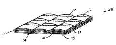
図5を参照すると、マイクロ波相互作用要素15の素材は、異なる素材の数層の組み合わせであり得る。通常、第1のプラスチックフィルム16上にマイクロ波相互作用素材14の薄い層を含むサセプタ12は、例えば接着剤のラミネーション(不図示)で、例えば紙のような寸法的に安定した基板20に接着されている。基板20は、閉塞セル28が通常マイクロ波相互作用要素15の素材で形成されるように、パターンのある接着剤26またはその他の素材を使用して、第2のプラスチックフィルム22に接着されている。閉塞セル28は蒸気移動に対して相当な耐性を示す。 Referring to FIG. 5, the material of the
任意に、付加的な基板層24は、図8で描写されているように、接着剤やその他の方法でマイクロ波相互作用要素素材と反対側の第1のプラスチックフィルム16に接着されてもよい。付加的な基板層24は、紙やその他の適切な素材の層であってもよく、加熱中に基板からひび割れたりはがれたりするサセプタフィルムの破片から食品(不図示)を保護するために設けられてもよい。マイクロ波相互作用要素15の素材は、図6に示されるように、実質的に平坦な、複数層のシートである。 Optionally, the
図7は、電子レンジ(不図示)からのマイクロ波エネルギーにさらされる、図5及び図6のマイクロ波相互作用要素15の例示的な素材を描写する。マイクロ波エネルギーの入射によりサセプタ12が加熱するにつれ、閉塞セル28内の第2のプラスチックフィルム22および基板20の間の狭い空間に通常保持されている水蒸気およびその他のガス、ならびに閉じ込められた空気が膨張する。閉塞セル28内の水蒸気および空気(またはその他の適切な物質)の膨張は、閉塞セル28の一方の側でサセプタ12および基板20に圧力を印加し、その反対側で第2のプラスチックフィルム22に圧力を印加する。閉塞セル28を形成する素材15の各側は、加熱および蒸気の膨張に、同時に、しかし独自に反応する。セル28は拡張または膨張し、第2のプラスチックフィルム22によって形成される底面34の上にある、サセプタ12および基板20のラミネーション内のチャネル(不図示)によって分離される、「枕」の、キルト状の上面32を形成する。この膨張は電圧を加えた電子レンジ内で1秒から15秒以内に生じる可能性があり、場合によっては2秒から10秒の間に生じることもある。 FIG. 7 depicts an exemplary material of the
セル28の膨張により、マイクロ波絶縁素材15が食品の表面に、より密着するのを可能にし、サセプタ12を食品のより近位に配置する。これにより、食品の対流加熱、ならびに伝導加熱によって、マイクロ波絶縁素材15が食品の表面に焦げ目をつけ、カリカリにする能力を高める。本発明のパッケージ3で使用されるマイクロ波絶縁素材15は、本発明の範囲から逸脱することなく、本明細書で説明されている素材以外を含んでもよく、別の方法で、配置され、構成され、設計されてもよいことを理解されたい。さらに、マイクロ波絶縁素材15の複数の層を、パッケージ3で使用してもよい。 The expansion of the
許容可能な一例によって、図2乃至図4で図示、および以下で説明されているように、食品Pを収容する、上方向に延在する側壁を有するトレイ7を形成するために、最初に上方向にサイドパネル27、29、41、43を折り曲げ、中央パネル23に対してボトムパネル21のコーナーパネル51、53、55、57を折り曲げることによって、パッケージ3がブランクから形成される。コーナーパネル51、53、55、57のそれぞれは、サイドパネル27、29に対して、それぞれ垂直に折り曲げられ、サイドパネル41、43にそれぞれ、おおむね向かい合った関係で配置されてもよい。コーナーパネル51、53、55、57は接着剤によって、サイドパネル41、43のうちの1つにそれぞれ取り付けてもよい。次に、フレキシブルフラップ11は、横方向の折り線61に沿って、図2に示された位置に上方向に折り曲げられる。図3で示されるように、フレキシブルフラップ11は、食品のまわりに配置するために、略C形のラップに形成される。C形のフレキシブルフラップ11は、食品Pの周囲に配置され、図4の位置に下方向に折り曲げられる。フレキシブルフラップ11は食品Pを包み、ボトムパネル21のサイドパネル43から延在する略平坦な上層81、湾曲部分83、および食品の底を包む略平坦な底層85を含む。食品Pは、フラップがトレイ7を覆うために下方向に折り曲げられるように、C形のフレキシブルフラップ11内に配置されてもよく、あるいは食品のまわりで成型され、食品を覆うフレキシブルフラップを有するトレイの中央パネル23上に食品を最初に配置してもよいことを理解されたい。図示される実施形態のフレキシブルフラップ11は、食品Pの周囲に配置され、食品を包み、覆う、マイクロ波絶縁素材15を含む、開放型クッキングスリーブを形成することを理解されたい。複数の横方向の折り線73は、フレキシブルフラップ11に必要な柔軟性を与え、フラップおよびそこに取り付けられたマイクロ波絶縁素材が、不規則な形状の食品の表面に密接に一致できるようにする。 By way of an acceptable example, the top is first raised to form a tray 7 with upwardly extending side walls containing food P, as illustrated in FIGS. 2-4 and described below. By bending the
調理の前において、マイクロ波絶縁素材15の一部が、フレキシブルフラップ11に包まれた不規則な形状の食品に密着していない場合もあり得る。そのように、食品の一部のみがサセプタ素材12と直接接触することになる。第1の実施形態の一形態に関して上述されるように、マイクロ波絶縁素材15のセル28の膨張により、サセプタ12を食品に対して膨張させ、食品の表面への接触を増やし、よってより効果的に加熱し、焦げ目を付け、および/またはカリカリにする。 Before cooking, a part of the
図9は、第1の実施形態と類似した方法で、食品Pを加熱するためのパッケージ103(図9A)を形成するために使用されるブランク101の形態で、本発明の第2の実施形態を示す。ブランク101が、フレキシブルフラップ107(広範には「カバー」)に取り付けられた第1のマイクロ波エネルギー相互作用要素105、および中央パネル111に取り付けられた第2のマイクロ波エネルギー相互作用要素109を含むことを除いては、パッケージ103は、第1の実施形態のパッケージ3に類似している。また、フレキシブルフラップ107が、食品Pを包むことなく、第2の実施形態のトレイ108を覆うように、フレキシブルフラップ107は、第1の実施形態のフラップ11よりも短い。 FIG. 9 is in the form of a blank 101 used to form a package 103 (FIG. 9A) for heating food P in a manner similar to the first embodiment, and in the second embodiment of the present invention. Indicates. The blank 101 includes a first microwave energy
トレイ108は、中央パネル111と、4つのサイドパネル121、122、123、124とを有する、第1の実施形態のボトムパネル21に類似する、ブランク101のボトムパネル113から形成される。ボトムパネル113は、サイドパネル121、123内に通気口117を有する。フレキシブルフラップ107は、横方向の折り線125でサイドパネル123に取り付けられており、フラップの横方向の縁部間に延在する4つの離間した横方向の折り線127を有する。第1のマイクロ波相互作用要素105は、第1のマイクロ波相互作用要素のそれぞれの角に略隣接した4つの位置で、接着剤129(概略的に図示)によってフレキシブルフラップ107に取り付けられている。第2のマイクロ波相互作用要素109は、第2のマイクロ波相互作用要素のそれぞれの角に略隣接した4つの位置で、接着剤133(概略的に図示)によってボトムパネル113の中央パネル111に取り付けられている。図9で示されるように、第1のマイクロ波相互作用要素105および第2のマイクロ波相互作用要素109は、共に長方形であるが、本発明の範囲から逸脱することなく、該要素は別様に成形されてもよい(例えば正方形、不規則な形、等)。本実施形態のマイクロ波相互作用要素105、109は、第1の実施形態に関して上述された素材に類似しているか、または同一のマイクロ波相互作用素材を備えてもよく、あるいはマイクロ波相互作用要素は本発明の範囲から逸脱することなく、別様に構成されてもよい。さらに、マイクロ波相互作用要素105、109は、マイクロ波絶縁素材の複数の層から成り得る。 The
以下で説明されている、許容可能な一方法によると、第2の実施形態のパッケージ103を使用するにあたり、トレイ108は最初にボトムパネル113から形成され、食品Pは第2のマイクロ波絶縁パネル109と接触してトレイ内に配置される。横方向の折り線125に沿ってフレキシブルフラップを折り曲げることにより、フレキシブルフラップ107でボトムパネル113から形成されたトレイ108を覆うことによって、食品Pを囲む。フレキシブルフラップ107を、様々な取り付け方法により、ボトムパネル113のサイドパネル121にしっかりと固定することが出来る。例えば、図示される実施形態では、フレキシブルフラップ107は、図9Aの閉じた位置でフレキシブルフラップを保持するために、トレイのサイドパネル121の中で係止用凹部146の中に収容されるサイズである切り目144によって形成される、係止用タブ142を有する。タブ142は、閉じた位置でフレキシブルフラップ107を保持するために、図9Aに示されている位置から外側に折り曲げ、係止用凹部146に挿入することができる。図9Aで示されているようにフレキシブルフラップ107が閉じられる際に、第1のマイクロ波相互作用要素105は、食品Pの上面に接触して、または密接して配置される。前の実施形態と同様に、パッケージの第1および第2のマイクロ波相互作用要素105、109は、パッケージ103が電子レンジで加熱される際、食品Pに焦げ目をつけ、カリカリにする。 According to one acceptable method described below, in using the
図9の実施形態で、ボトムパネル113はブランク101の長手方向において幅L5を有し、フレキシブルフラップ107はブランクの長手方向において幅L6を有している。図示される実施形態で、フレキシブルフラップ107の幅L6はボトムパネル113の幅L5にほぼ等しい。特定の一実施形態で、幅L5および幅L6は、約5と4分の1インチ(133mm)である。ここで示される全ての寸法情報は、例示的な実施形態の説明を目的とし、本発明の範囲を制限するためのものではない。 In the embodiment of FIG. 9, the
図10乃至図11Aは本発明のパッケージ202(図11A)の第3の実施形態を示す。トレイ206がトレイブランク201(図10)から形成されること、およびカバー208がカバーブランク203(図11)から形成されることを除き、パッケージ202は前の実施形態に類似している。トレイおよびカバーブランク201、203は、前の実施形態に類似の方法で、食品を加熱するためのパッケージ202を形成するために協働する。 FIGS. 10-11A show a third embodiment of the package 202 (FIG. 11A) of the present invention.
図11を参照すると最もよく分かるように、カバーブランク203は、パネルのそれぞれの角に略隣接して位置する接着剤211(概略的に図示)によって第1のマイクロ波絶縁パネル207が取り付けられている、略長方形のパネル205を含む。カバーブランク203は、パネルの横方向の縁部と、折り線で画定された3つの独立して可動である部分216の間に延在する、2つの離間した折り線215を含む。 As best seen with reference to FIG. 11, the cover blank 203 has a first
図10を参照すると最もよく分かるように、トレイブランク201は、中央パネルのそれぞれの角に略隣接して位置する接着剤225(概略的に図示)によって第2のマイクロ波絶縁パネル221が取り付けられている、略長方形の中央パネル217を含む。前の実施形態と同様に、トレイブランク201は、トレイ206を形成する際に、中央パネル217に対して配置するように、サイドパネル227、229、241、243およびコーナーパネル251、253、255、257を含む。 As best seen with reference to FIG. 10, the
本実施形態のパッケージ202は、前の実施形態と類似の方法で、トレイブランク201から食品を保持するトレイ206を最初に形成することによって組み立てられ得ることを理解されたい。食品Pは、マイクロ波相互作用要素221と接触してトレイ206の中央パネル217の上に配置される。図11Aに概して示されるように、パネル216を配置するために、折り線215に沿って折り曲げることにより、カバーブランク203をカバー208に形成し、トレイ206を覆う。カバー208は、第1のマイクロ波絶縁パネル207を食品Pの上面に接触するかまたは密接するように配置するために、トレイ206の上部に配置される。第1および第2のマイクロ波相互作用要素207、221が食品に焦げ目を付け、カリカリにし、加熱し、および/または調理するように、上記で説明した方法に類似の方法で、食品Pが加熱される。カバー208およびトレイ206は、本発明の範囲から逸脱することなく、食品Pの一面を加熱するために別々に使用されてもよいことを理解されたい。前の実施形態と同様に、第1および第2のマイクロ波相互作用要素207、221はマイクロ波絶縁素材の1つ以上の層から成り得る。 It should be understood that the
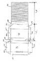
図12は、本発明のパッケージ302を形成するために使用されるブランク301の第4の実施形態を示す。ブランク301は、第1の実施形態のボトムパネル21に類似のボトムパネル305と、横方向の折り線311に沿って、ボトムパネルに折り曲げ可能に取り付けられたトップパネル307と、第1の実施形態のフレキシブルフラップ11のような、横方向の折り線315に沿ってボトムパネルに取り付けられたフレキシブルフラップ313とを含む。ボトムパネル305は、中央パネル323と、トレイ内にボトムパネルを形成するために中央パネルに折り曲げ可能に取り付けられた4つのサイドパネル327、329、341、343とを含む。図示される実施形態では、トップパネル307は、中央パネル316と、中央パネルに折り曲げ可能に取り付けられた4つのサイドパネル320、322、324、326を含む。中央パネル316と、トップパネル307のサイドパネル320、322、326とは、ふた308を形成し、中央パネル323と、4つのサイドパネル327、329、341、343は、トレイ310を形成する。ふた308は折り線311でトレイ310に折り曲げ可能に取り付けられている。ふた308は、第4の実施形態のパッケージ302を閉じるためにトレイ310と協働する。 FIG. 12 shows a fourth embodiment of a blank 301 used to form the
第1の実施形態と同様に、マイクロ波絶縁層(不図示)は、フレキシブルフラップ313およびボトムパネル305の内部表面の少なくとも一部に取り付けられてもよい。本実施形態では、フレキシブルフラップ313によって包まれている食品を覆うために、トップパネル307によって形成されたふた308が、横方向の折り線311で折り曲げられていることを除けば、第1の実施形態のブランク1と類似した方法で、ブランク301は食品Pを加熱するためのパッケージ302に形成される。トップおよびボトムパネル307、305から形成されるふた308およびトレイ310は、協働して加熱中に食品Pを完全に囲む。加熱中に食品Pを囲むための、トップパネル307によって形成されたふた308の使用により、さらなる絶縁層を設け、食品をさらに加熱し、マイクロ波絶縁層等によって発生した熱が、パッケージ302の上面または側面から逃れるのを防ぐ。前の実施形態と同様に、マイクロ波絶縁層は、本発明の範囲から逸脱することなく、マイクロ波絶縁素材の1つ以上の層を含んでもよい。 Similar to the first embodiment, a microwave insulating layer (not shown) may be attached to at least a part of the inner surfaces of the
図12の実施形態では、ボトムパネル305はブランク301の長手方向において幅L7を有し、フレキシブルフラップ313はブランクの長手方向において長さL8を有する。図示される実施形態で、フレキシブルフラップ313の長さL8は、ボトムパネル305の幅L7よりも長い。特定の一実施形態では、幅L7は約6と2分の1インチ(165mm)であり、長さL8は約10インチ(254mm)である。ここで示される全ての寸法情報は、例示的な実施形態の説明を目的とし、本発明の範囲を制限するためのものではない。 In the embodiment of FIG. 12, the
便宜上、食品およびパッケージはここでは上面、底面および側面を有するように記載される。多くの場合、パッケージ若しくは食品の上面、底面および側面は、食品が配置されている表面および見る者の視野に相対的である。上面、底面、または側面への参照は、本発明の範囲に特定の制限を課するためのものではなく、単にその特徴を説明するために言及する容易な方法を提供すると理解されたい。 For convenience, food and packages are described herein as having a top surface, a bottom surface, and side surfaces. In many cases, the top, bottom and sides of the package or food are relative to the surface on which the food is placed and the viewer's field of view. It should be understood that references to the top, bottom, or sides are not intended to impose specific limitations on the scope of the invention, but merely provide an easy way to mention its features.
様々なマイクロ波エネルギー相互作用要素が、本発明の使用に適切でありうる。例えば、マイクロ波エネルギー相互作用要素は、食品の特定の範囲に焦げ目をつけ、および/またはカリカリにするのを促進し、食品を加熱し過ぎるのを防ぐために、マイクロ波エネルギーから食品のある特定の範囲を遮へいし、または食品の特定の範囲にむけ、またはそこを離れてマイクロ波エネルギーを伝達し得る。特定の構造体および食品のために、必要または所望に応じて、マイクロ波エネルギーを吸収、マイクロ波エネルギーを伝達、マイクロ波エネルギーを反射、またはマイクロ波エネルギーを導くために、各マイクロ波相互作用要素は、特定の構造に配置された1つ以上のマイクロ波エネルギー相互作用素材またはセグメントを備える。 A variety of microwave energy interactive elements may be suitable for use with the present invention. For example, a microwave energy interactive element may help to burn and / or crisp certain areas of food and to prevent the food from being overheated. The microwave energy can be transmitted to or away from a range or to a specific range of food. Each microwave interaction element to absorb microwave energy, transmit microwave energy, reflect microwave energy, or direct microwave energy as needed or desired for a particular structure and food Comprises one or more microwave energy interactive materials or segments arranged in a particular structure.
マイクロ波相互作用要素は、扱いしやすくするために、および/またはマイクロ波相互作用素材と食品との間の接触を防ぐために、マイクロ波不活性、または透過基板上で支持されてもよい。限定するためではなく便宜上、マイクロ波透過基板上に支持されたマイクロ波相互作用要素は、マイクロ波相互作用、およびマイクロ波不活性要素、または構成要素の両方を含むと理解されるが、そのような構造体は以下「マイクロ波相互作用ウェブ」と称する。 The microwave interactive element may be supported on a microwave inert or transmissive substrate for ease of handling and / or to prevent contact between the microwave interactive material and the food product. For convenience, but not by way of limitation, a microwave interaction element supported on a microwave transparent substrate is understood to include both microwave interaction and microwave inactive elements, or components, but as such Such a structure is hereinafter referred to as a “microwave interaction web”.
マイクロ波エネルギー相互作用素材は、例えば、金属箔として提供される金属または合金、真空蒸着金属または合金、または金属インク、有機インク、無機インク、金属ペースト、有機ペースト、無機ペースト、またはその任意の組み合わせのような、導電性または半導体の素材であり得る。本発明での使用に適切であり得る金属および合金の例としては、これに限定されないが、アルミニウム、クロム、銅、インコネル合金(ニオブとのニッケル・クロム・モリブデン合金)、鉄、マグネシウム、ニッケル、ステンレス鋼、スズ、チタン、タングステン、およびその合金の任意の組み合わせが挙げられる。 The microwave energy interactive material may be, for example, a metal or alloy provided as a metal foil, a vacuum deposited metal or alloy, or a metal ink, organic ink, inorganic ink, metal paste, organic paste, inorganic paste, or any combination thereof It can be a conductive or semiconductor material. Examples of metals and alloys that may be suitable for use in the present invention include, but are not limited to, aluminum, chromium, copper, inconel alloys (nickel-chromium-molybdenum alloys with niobium), iron, magnesium, nickel, Include any combination of stainless steel, tin, titanium, tungsten, and alloys thereof.
代替的に、マイクロ波エネルギー相互作用素材は、金属酸化物を備えてもよい。本発明での使用に適切であり得る金属酸化物の例としては、これに限定されないが、必要に応じて電気伝導性素材と併せて使用される、アルミニウム、鉄およびスズの酸化物が挙げられる。本発明での使用に適切な金属酸化物の別の例は、酸化インジウムスズ(ITO)である。ITOは、加熱効果、遮へい効果、焦げ目付けおよび/またはカリカリにする効果、またはその組み合わせを提供するために、マイクロ波エネルギー相互作用素材として使用できる。例えば、サセプタを形成するために、ITOは透明なポリマーフィルムの上にスパッタされてもよい。スパッタの過程は、通常、金属蒸着に使用される蒸発蒸着過程よりも低温で行う。ITOはより均一な結晶構造を有し、したがって、大抵のコーティング厚で透明である。さらに、ITOは、加熱または電磁場管理効果(field management effect)に使用できる。またITOは、金属よりも欠陥が少ない可能性があり、よってITOの厚膜コーティングは、アルミニウムのような金属の厚膜コーティングよりも電磁場管理に適したものになる。 Alternatively, the microwave energy interactive material may comprise a metal oxide. Examples of metal oxides that may be suitable for use in the present invention include, but are not limited to, aluminum, iron and tin oxides used in conjunction with electrically conductive materials as needed. . Another example of a metal oxide suitable for use in the present invention is indium tin oxide (ITO). ITO can be used as a microwave energy interactive material to provide a heating effect, a shielding effect, a scorching and / or crunching effect, or a combination thereof. For example, ITO may be sputtered onto a transparent polymer film to form a susceptor. The sputtering process is usually performed at a lower temperature than the evaporation deposition process used for metal deposition. ITO has a more uniform crystal structure and is therefore transparent at most coating thicknesses. In addition, ITO can be used for heating or field management effects. ITO can also have fewer defects than metals, so ITO thick film coatings are more suitable for electromagnetic field management than thick film coatings of metals such as aluminum.
代替的に、マイクロ波エネルギー相互作用素材は、適した導電性、半導体、または非導電性の人工誘電体または強誘電体を備えてもよい。人工誘電体は、重合体、またはその他の適したマトリクスまたはバインダー内に、導電性の、細分化された材料を備え、例えばアルミニウムといった電気伝導性の金属の破片を含みうる。 Alternatively, the microwave energy interactive material may comprise a suitable conductive, semiconductor, or non-conductive artificial dielectric or ferroelectric. The artificial dielectric comprises a conductive, fragmented material in a polymer, or other suitable matrix or binder, and may include fragments of electrically conductive metal such as aluminum.
一例において、マイクロ波相互作用要素は、マイクロ波エネルギーを吸収する傾向があるマイクロ波相互作用素材の薄い層を備えてもよく、それによって食品の接触面で熱を発生させる。そのような要素は、しばしば食品の表面に焦げ目を付け、および/またはカリカリにするのを促進するのに使用される(「焦げ目を付けるおよび/またはカリカリにする要素」と称される場合がある)。フィルムまたはその他の基板上で支持される場合、そのような要素は「サセプタフィルム」または単に「サセプタ」と称される場合がある。しかしながら、本明細書で説明される要素のように、その他のマイクロ波エネルギー相互作用要素が企図される。 In one example, the microwave interactive element may comprise a thin layer of microwave interactive material that tends to absorb microwave energy, thereby generating heat at the food contact surface. Such elements are often used to promote charring and / or crunchiness on the surface of food (sometimes referred to as “scorching and / or crunchy elements”). ). When supported on a film or other substrate, such an element may be referred to as a “susceptor film” or simply “susceptor”. However, other microwave energy interactive elements are contemplated, such as the elements described herein.
別の例としては、マイクロ波相互作用要素は、マイクロ波エネルギーから食品の1つ以上の選択された部分を遮へいするために十分な厚みを有する金属のホイルを備えてもよい(「遮へい要素」と称される場合がある」)。そのような遮へい要素は、加熱中、食品が焦げやすい、または乾燥しやすい場所に使用されうる。 As another example, the microwave interaction element may comprise a metal foil having a thickness sufficient to shield one or more selected portions of the food from microwave energy (“shielding element”). Sometimes referred to as ")." Such shielding elements can be used in places where food is susceptible to scorching or drying during heating.
遮へい要素は、使用される特定用途によって、様々な素材から形成され、様々な構造を有しうる。通常、遮へい要素は、例えばアルミニウム、銅、またはステンレス鋼のような、導電性の反射金属または合金から形成される。遮へい要素は、概して、約0.000285インチから約0.05インチの厚みを有し得る。一態様において、遮へい要素は約0.0003インチから約0.03インチの厚みを有する。また別の態様において、遮へい要素は、約0.00035インチから約0.020インチ、例えば0.016インチの厚みを有する。 The shielding element may be formed from a variety of materials and have a variety of structures, depending on the particular application used. Typically, the shielding element is formed from a conductive reflective metal or alloy, such as, for example, aluminum, copper, or stainless steel. The shielding element may generally have a thickness of about 0.000285 inches to about 0.05 inches. In one aspect, the shielding element has a thickness of about 0.0003 inches to about 0.03 inches. In yet another aspect, the shielding element has a thickness of about 0.00035 inches to about 0.020 inches, such as 0.016 inches.
さらに別の例として、マイクロ波相互作用要素は、参照によって全て組み込まれる、米国特許第6,204,492号、第6,433,322号、第6,552,315号、および第6,677,563号で説明されるものだがこれに限らない、セグメント化されたホイルから成りうる。セグメント化されたホイルは連続的ではないが、そのようなセグメントの適切に離間したグループは、しばしば食品の特定の範囲にマイクロ波エネルギーを導くための伝達要素としての役割を果たす。またそのようなホイルは、例えばサセプタのような、焦げ目を付けるおよび/またはカリカリにする要素と組み合わせて使用され得る。 As yet another example, microwave interactive elements are all incorporated by reference, US Pat. Nos. 6,204,492, 6,433,322, 6,552,315, and 6,677. 563, but is not limited to this, it can consist of segmented foils. Although segmented foils are not continuous, appropriately spaced groups of such segments often serve as transfer elements for directing microwave energy to specific areas of food. Such foils can also be used in combination with charring and / or crunchy elements such as, for example, susceptors.
本明細書で説明、またはこれによって企図された多数のマイクロ波相互作用要素はいずれも、大幅に中断、または途切れることなく実質的に連続的であってもよく、または、例えばマイクロ波エネルギーを伝達する1つ以上の割れ目または開口を含み、不連続的であってもよい。割れ目または開口は、食品の特定の範囲を選択的に加熱するための大きさに決められ、配置されてもよい。そのような割れ目または開口の数、形状、サイズおよび位置は、形成された構造体の種類、その中で、またはその上で加熱される食品、望ましい遮へい、焦げ目を付けるおよび/またはカリカリにする程度、食品の均一な加熱を実現するためにマイクロ波エネルギーの直接の照射が必要または望まれるか、直接加熱を通じて食品の温度の変化を調節する必要性、および通気が必要か、また通気がどの程度必要かによる特定用途で変わる。 Any of the many microwave interactive elements described or contemplated herein may be substantially continuous without significant interruption or interruption, or transmit microwave energy, for example. Including one or more cracks or openings that may be discontinuous. The breaks or openings may be sized and arranged to selectively heat a specific area of the food product. The number, shape, size, and location of such cracks or openings depends on the type of structure formed, the food heated in or on it, the desired shielding, charring and / or crunchy , Whether direct irradiation of microwave energy is required or desired to achieve uniform heating of the food, the need to adjust the temperature change of the food through direct heating, and whether aeration is needed, and how much ventilation It depends on the specific application depending on the necessity
開口は構造体を形成するために使用される素材内の、物理的開口または空隙、または非物理的な「開口」であり得ることが理解されるであろう。非物理的な開口は、不活性化またはその他によってマイクロ波エネルギー不活性な構造体の一部であるか、あるいはマイクロ波エネルギーを透過させる構造体の一部であってもよい。よって、例えば、開口は、マイクロ波エネルギー活性素材なしで形成された構造体の一部であり得るか、また、あるいは不活性化されたマイクロ波エネルギー活性素材で形成された構造体の一部であり得る。物理的および非物理的な開口の両方は、マイクロ波エネルギーによって食品を直接加熱するのを可能にする一方で、物理的な開口はまた、蒸気やその他の気体が食品から放出されるのを可能にする通気機能を提供する。またカートンの過熱またはチャーリングを防ぐために、1つ以上の切れ目または不活性領域を作製することも、有益であり得る。 It will be appreciated that the openings can be physical openings or voids, or non-physical “openings” in the material used to form the structure. The non-physical aperture may be part of a structure that is inactive or otherwise microwave energy inactive, or part of a structure that is transparent to microwave energy. Thus, for example, the aperture can be part of a structure formed without a microwave energy active material, or can be part of a structure formed with a deactivated microwave energy active material. possible. Both physical and non-physical openings allow food to be heated directly by microwave energy, while physical openings also allow vapors and other gases to be released from the food Providing ventilation function. It may also be beneficial to create one or more cuts or inactive regions to prevent overheating or charring of the carton.
上術のように、上記の要素、および本明細書で企図されたその他の多数のものはいずれも、基板上で支持されてもよい。基板は通常、例えばポリマーフィルムやその他のポリマー素材を備える。本明細書において、「ポリマー」や「ポリマー素材」という用語は、ホモポリマー、例えばブロック、グラフト、ランダムおよび交互コポリマー等のコポリマー、ターポリマー等、およびそのブレンドおよび変性物が挙げられるが、これに限定されない。さらに、別途具体的に制限されない限り、「ポリマー」という用語は、分子の可能な全ての幾何学形状を含むものとする。これらの形状は、イソタクチック、シンジオタクチック、そしてランダム対称を含むが、これに限定されない。 As above, any of the above elements, and many others contemplated herein, may be supported on a substrate. The substrate typically comprises a polymer film or other polymer material, for example. As used herein, the terms “polymer” and “polymer material” include homopolymers, such as copolymers, terpolymers, and the like, such as blocks, grafts, random and alternating copolymers, and blends and modifications thereof. It is not limited. Further, unless otherwise specifically limited, the term “polymer” is intended to include all possible geometric shapes of the molecule. These shapes include, but are not limited to isotactic, syndiotactic and random symmetries.
フィルムの厚さは通常、約35gaugeから約10milであり得る。一態様において、フィルムの厚さは約40から約80gaugeである。また別の態様において、フィルムの厚さは約45から約50gaugeである。さらに別の態様において、フィルムの厚さは約48gaugeである。適切であり得るポリマーフィルムの例としては、これらに限定されないが、ポリオレフィン、ポリエステル、ポリアミド、ポリイミド、ポリスルフォン、ポリエーテルケトン、セロファン、またその組み合わせどれもが挙げられる。紙やラミネート紙、金属酸化物、ケイ酸塩、セルロース誘導体、またそれらの任意の組み合わせのような、その他の非導電性の基板素材も使用され得る。 The film thickness can typically be from about 35 gauge to about 10 mils. In one embodiment, the film thickness is from about 40 to about 80 gauge. In yet another embodiment, the film thickness is from about 45 to about 50 gauge. In yet another embodiment, the film thickness is about 48 gauge. Examples of polymer films that may be suitable include, but are not limited to, polyolefins, polyesters, polyamides, polyimides, polysulfones, polyether ketones, cellophanes, and any combination thereof. Other non-conductive substrate materials such as paper and laminated paper, metal oxides, silicates, cellulose derivatives, and any combination thereof may also be used.
一例において、ポリマーフィルムはポリエチレンテレフタレート(PET)を備える。ポリエチレンテレフタレートフィルムは、例えば、Graphic Packaging International(Marietta, Georgia)から市販されている、QWIKWAVE(登録商標)サセプタおよびMICRORITE(登録商標)サセプタラミネーションといったような、市販のサセプタで使用されている。基板としての使用に適している可能性のあるポリエチレンテレフタレートフィルムの例としては、DuPont Teijan Films(Hopewell,Virginia)から市販されているMELINEX(登録商標)フィルム、SKC,Inc.(Covington,Georgia)から市販されているSKYROLフィルム、Toray Films(Front Royal,VA)から市販されているBARRIALOX PETフィルム、およびToray Films(Front Royal,VA)から市販されているQU50 High Barrier Coated PETフィルムが挙げられるが、これらには限定されない。 In one example, the polymer film comprises polyethylene terephthalate (PET). Polyethylene terephthalate films are used in commercial susceptors such as, for example, QWIKWAVE® susceptor and MICRORITE® susceptor lamination, commercially available from Graphic Packaging International (Marietta, Georgia). Examples of polyethylene terephthalate films that may be suitable for use as substrates include MELINEX® film, SKC, Inc., commercially available from DuPont Teijan Films (Hopewell, Virginia). SKYROL film commercially available from Covington, Georgia, BARRIALOX PET film commercially available from Toray Films (Front Royal, VA), and QUA50 High Barri PET film commercially available from Toray Films (Front Royal, VA) However, it is not limited to these.
ポリマーフィルムは、例えば、印刷適性、耐熱性、またはその他の特性といったような、様々な特性を紙や板紙ウェブに与えるために選択され得る。特定の一例として、ポリマーフィルムは水分バリア、酸素バリア、またはその組み合わせを提供するために、選択され得る。そのようなバリアフィルムの層は、バリア特性を有するポリマーフィルムから、または所望に応じて、その他のバリア層やコーティングから形成され得る。適切なポリマーフィルムには、これらには限定されないが、エチレンビニルアルコール、バリアナイロン、ポリ塩化ビニリデン、バリアフッ素重合体、ナイロン6、ナイロン6,6、共押し出しナイロン6/EVOH/ナイロン6、酸化ケイ素コーティングフィルム、バリアポリエチレンテレフタレート、またその任意の組み合わせが挙げられる。 The polymer film can be selected to give the paper or paperboard web various properties, such as, for example, printability, heat resistance, or other properties. As a specific example, a polymer film can be selected to provide a moisture barrier, an oxygen barrier, or a combination thereof. Such barrier film layers can be formed from polymer films having barrier properties, or from other barrier layers and coatings as desired. Suitable polymer films include, but are not limited to, ethylene vinyl alcohol, barrier nylon, polyvinylidene chloride, barrier fluoropolymer, nylon 6, nylon 6,6, coextruded nylon 6 / EVOH / nylon 6, silicon oxide Examples thereof include a coating film, barrier polyethylene terephthalate, and any combination thereof.
本発明での使用に適切であり得るバリアフィルムの一例として、Honeywell International(Pottsville、Pennsylvania)から市販のCAPRAN(登録商標) EMBLEM1200Mナイロン6フィルムがある。適しうるバリアフィルムの別の例として、同様にHoneywell Internationalから市販のCAPRAN(登録商標) OXYSHIELD OBS一軸延伸共押し出しナイロン6/エチレンビニルアルコール(EVOH)/ナイロン6フィルムがある。本発明での使用に適切であり得るバリアフィルムのまた別の例として、Enhance Packaging Technologies(Webster、New York)から市販のDARTEK(登録商標) N−201ナイロン6,6フィルムがある。さらなる例としては、上記のToray Films(Front Royal、VA)から市販のBARRIALOX PETフィルム、およびToray Films(Front Royal、VA)から市販のQU50 High Barrier Coated PETフィルムが挙げられる。 One example of a barrier film that may be suitable for use in the present invention is the CAPRAN® EMBLEM 1200M nylon 6 film commercially available from Honeywell International (Pottsville, Pennsylvania). Another example of a barrier film that may be suitable is CAPRAN® OXYSHIELD OBS uniaxially stretched coextruded nylon 6 / ethylene vinyl alcohol (EVOH) / nylon 6 film, also commercially available from Honeywell International. Another example of a barrier film that may be suitable for use in the present invention is DARTEK® N-201 nylon 6,6 film, commercially available from Enhancement Packaging Technologies (Webster, New York). Further examples include BARRIALOX PET film commercially available from Toray Films (Front Royal, VA) and QUA50 High Barrier Coated PET film commercially available from Toray Films (Front Royal, VA).
さらにその他のバリアフィルムには、Sheldahl Films(Northfield、Minnesota)から市販のフィルムのような、酸化ケイ素コーティングフィルムがある。よって、一例として、サセプタは、例えば、ポリエチレンテレフタレートのようなフィルムを含み、酸化ケイ素の層がフィルム上にコーティングされ、ITOまたはその他の素材が酸化ケイ素上に蒸着されている構造を有し得る。必要または所望に応じて、処理中、個々の層を破損から保護するために、付加的な層またはコーティングが設けられ得る。 Still other barrier films include silicon oxide coated films, such as those commercially available from Sheldahl Films (Northfield, Minnesota). Thus, by way of example, a susceptor may include a film, such as polyethylene terephthalate, having a structure in which a layer of silicon oxide is coated on the film and ITO or other material is deposited on the silicon oxide. Additional layers or coatings can be provided as needed or desired to protect individual layers from damage during processing.
ASTM D3985を使用した測定により、バリアフィルムは、約20cc/m2/日未満の酸素透過率(OTR)を有し得る。一態様において、バリアフィルムは約10cc/m2/日未満のOTRを有する。また別の態様において、バリアフィルムは約1cc/m2/日未満のOTRを有する。さらに別の態様において、バリアフィルムは約0.5cc/m2/日未満のOTRを有する。さらに別の態様において、バリアフィルムは約0.1cc/m2/日未満のOTRを有する。 As measured using ASTM D3985, the barrier film can have an oxygen transmission rate (OTR) of less than about 20 cc / m 2 / day. In one aspect, the barrier film has an OTR of less than about 10 cc / m2 / day. In yet another aspect, the barrier film has an OTR of less than about 1 cc / m2 / day. In yet another aspect, the barrier film has an OTR of less than about 0.5 cc / m2 / day. In yet another aspect, the barrier film has an OTR of less than about 0.1 cc / m2 / day.
ASTM F1249を使用した測定により、バリアフィルムは約100g/m2/日未満の水蒸気透過率(WVTR)を有し得る。一態様において、バリアフィルムは約50g/m2/日未満の水蒸気透過率を有する。また別の態様において、バリアフィルムは約15g/m2/日未満のWVTRを有する。さらに別の態様において、バリアフィルムは約1g/m2/日未満のWVTRを有する。さらに別の態様において、バリアフィルムは約0.1g/m2/日未満のWVTRを有する。またさらに別の態様において、バリアフィルムは約0.05g/m2/日未満のWVTRを有する。 The barrier film can have a water vapor transmission rate (WVTR) of less than about 100 g / m 2 / day as measured using ASTM F1249. In one aspect, the barrier film has a water vapor transmission rate of less than about 50 g / m 2 / day. In yet another aspect, the barrier film has a WVTR of less than about 15 g / m2 / day. In yet another aspect, the barrier film has a WVTR of less than about 1 g / m2 / day. In yet another aspect, the barrier film has a WVTR of less than about 0.1 g / m2 / day. In yet another aspect, the barrier film has a WVTR of less than about 0.05 g / m2 / day.
また金属酸化物、ケイ酸塩、セルロース誘導体、またそれらの組み合わせのようなその他の非導電性の基板素材も、本発明により使用され得る。 Other non-conductive substrate materials such as metal oxides, silicates, cellulose derivatives, and combinations thereof may also be used according to the present invention.
マイクロ波エネルギー相互作用素材は、任意の適した方法で基板に適用されてもよく、また場合によっては、マイクロ波エネルギー相互作用素材は、基板の上に印刷され、押し出され、スパッタされ、蒸着されるか、またはラミネートされる。マイクロ波エネルギー相互作用素材は、食品への所望の加熱効果を達成するために、任意のパターンで、また任意の技術を使用して、基板に適用され得る。 The microwave energy interactive material may be applied to the substrate in any suitable manner, and in some cases, the microwave energy interactive material may be printed, extruded, sputtered, deposited on the substrate. Or laminated. The microwave energy interactive material can be applied to the substrate in any pattern and using any technique to achieve the desired heating effect on the food product.
マイクロ波相互作用要素またはマイクロ波相互作用ウェブは、構造体を形成するために、寸法安定性のある、マイクロ波エネルギー透過支持体(以下「マイクロ波透過支持体」、「マイクロ波不活性支持体」または「支持体」と称する)に結合されているか、または覆っていてもよい。より柔軟な構造体が形成される、別の態様において、支持体は、約15から約60lbs/ream、例えば約20から約40lbs/reamの基本重量を通常有する、紙の、または紙ベースの素材から成り得る。ある特定の例で、紙は約25lbs/reamの基本重量を有する。 Microwave interactive elements or microwave interactive webs are dimensionally stable, microwave energy transmissive supports (hereinafter “microwave transmissive supports”, “microwave inert supports” to form structures. Or “support”) or may be covered. In another embodiment, where a more flexible structure is formed, the support is a paper or paper-based material that typically has a basis weight of about 15 to about 60 lbs / ream, such as about 20 to about 40 lbs / ream. It can consist of In one particular example, the paper has a basis weight of about 25 lbs / ream.
任意に、本明細書で説明、または企図された様々なブランクまたはその他の構造体の1つ以上の部分が、ニス、クレイ、またはその他の素材で、そのうちの1つまたはその組み合わせで、コーティングされ得る。例えば、マイクロ波エネルギー相互作用素材は、円、ループ、六角形、島状、正方形、長方形、八角形等を含む、連続的または不連続的な層またはコーティングで提供され得る。本発明での使用に適切であり得る様々なパターンおよび方法の例が、参照することにより全て本書に組み込まれる、米国特許第7,019,271号、第6,765,182号、第6,717,121号、第6,677,563号、第6,552,315号、第6,455,827号、第6,433,322号、第6,414,290号、第6,251,451号、第6,204,492号、第6,150,646号、第6,114,679号、第5,800,724号、第5,759,422号、第5,672,407号、第5,628,921号、第5,519,195号、第5,424,517号、第5,410,135号、第5,354,973号、第5,340,436号、第5,266,386号、第5,260,537号、第5,221,419号、第5,213,902号、第5,117,078号、第5,039,364号、第4,963,424号、第4,936,935号、第4,890,439号、第4,775,771号、第4,865,921号、およびRe.34,683号で提供されている。ここでマイクロ波エネルギー相互作用素材のパターンの特別な例が示され、説明されているが、マイクロ波エネルギー相互作用素材のその他のパターンが、本発明によって企図されると理解されたい。 Optionally, one or more portions of various blanks or other structures described or contemplated herein are coated with varnish, clay, or other material, one or a combination thereof. obtain. For example, the microwave energy interactive material can be provided in a continuous or discontinuous layer or coating, including circles, loops, hexagons, islands, squares, rectangles, octagons, and the like. Examples of various patterns and methods that may be suitable for use in the present invention are all incorporated herein by reference, U.S. Patent Nos. 7,019,271, 6,765,182, 6, No. 717,121, No. 6,677,563, No. 6,552,315, No. 6,455,827, No. 6,433,322, No. 6,414,290, No. 6,251 451, 6,204,492, 6,150,646, 6,114,679, 5,800,724, 5,759,422, 5,672,407 5,628,921, 5,519,195, 5,424,517, 5,410,135, 5,354,973, 5,340,436, No. 5,266,386, No. 5,260,537, No. , 221,419, 5,213,902, 5,117,078, 5,039,364, 4,963,424, 4,936,935, 4,890 , 439, 4,775,771, 4,865,921, and Re. 34,683. Although specific examples of microwave energy interactive material patterns are shown and described herein, it should be understood that other patterns of microwave energy interactive material are contemplated by the present invention.
例えば、剛体の、または半剛体の構造体が形成される一態様において、支持体の全ての部分または1部分が、構造体への使用に先立って、ブランクに切断される可能性のある板紙素材から少なくとも部分的に形成され得る。例えば、支持体は、約60から約330lbs/ream(つまり、lbs/3,000ft2)、例えば約80から約140lbs/reamの基本重量を有する板紙から形成され得る。板紙は、一般的には、約6から約30mils、例えば約12から約28milsの厚さを有し得る。ある特別な例において、板紙は約18milsの厚さがあり、また約100lbs/reamから約300lbs/reamの基本重量を有する。いかなる適切な板紙も、Graphic Packaging Internationalから市販されているSUS(登録商標)ボードのような、例えば無地漂白、または無地無漂白クラフト板紙に使用され得る。For example, in one embodiment in which a rigid or semi-rigid structure is formed, all or one part of the support may be cut into blanks prior to use in the structure. Can be formed at least in part. For example, the support may be formed from paperboard having a basis weight of about 60 to about 330 lbs / ream (ie, lbs / 3,000 ft2 ), for example, about 80 to about 140 lbs / ream. The paperboard may generally have a thickness of about 6 to about 30 mils, such as about 12 to about 28 mils. In one particular example, the paperboard is about 18 mils thick and has a basis weight of about 100 lbs / ream to about 300 lbs / ream. Any suitable paperboard can be used, for example, plain bleached or plain unbleached kraft paperboard, such as SUS® board commercially available from Graphic Packaging International.
さらに、ブランクやその他の構造体は、上記の物のように、片面または両面を、例えば蒸気および/または酸素バリア層でコーティングされ得る。本発明に従って、いかなる適切な蒸気および/または酸素バリア素材も使用され得る。適切であり得る素材の例としては、これらには限定されないが、ポリ塩化ビニリデン、エチレンビニルアルコール、DuPont DARTEK(登録商標)ナイロン6,6フィルム、および上記のその他のものが挙げられる。 Furthermore, blanks and other structures can be coated on one or both sides, for example with a vapor and / or oxygen barrier layer, as described above. Any suitable vapor and / or oxygen barrier material may be used in accordance with the present invention. Examples of materials that may be suitable include, but are not limited to, polyvinylidene chloride, ethylene vinyl alcohol, DuPont DARTEK® nylon 6,6 film, and others described above.
代わりに、または追加的に、本発明のどのブランク、パッケージまたはその他の構造体も、吸収性、撥水性、不透過度、色、印刷適性、剛性またはクッション性等、その他の属性を与えるために、その他の素材でコーティング、またはラミネートされ得る。例えば、吸収力のあるサセプタは、2004年8月25日付申請の、米国仮特許出願第60/604,637号、および2005年8月25日付申請の、ミドルトンらによる、「Absorbent Microwave Interactive Packaging」と題された米国仮特許出願第11/211,858号で説明されているが、その双方は全て、参照することにより本明細書に組み込まれる。さらに、ブランクまたはその他の構造体は、その上に印刷された図または印(indicia)を含み得る。 Alternatively or additionally, any blank, package or other structure of the present invention may be used to provide other attributes such as absorbency, water repellency, opacity, color, printability, stiffness or cushioning. , Coated with other materials, or laminated. For example, an absorbent susceptor is described in US Provisional Patent Application No. 60 / 604,637, filed Aug. 25, 2004, and Middleton et al., “Absorbent Microwave Interactive Packaging”, filed Aug. 25, 2005. , Both of which are incorporated herein by reference. In addition, blanks or other structures may include figures or indicia printed thereon.
要素および素材のいくつかの組み合わせと共に、マイクロ波相互作用要素は、基板または支持体から視覚的に区別しやすい、灰色や銀色を有し得ると理解されたい。しかしながら、場合によっては、色や外観が均一であるウェブや構造体を提供するのが望ましいこともあり得る。特に顧客が、例えば無地や特定のパターンのような、ある視覚属性を有するパッケージや容器に慣れている場合、そのようなウェブや構造体は、顧客にとってより見て美しいこともあり得る。よって、例えば、マイクロ波相互作用要素を基板に結合するために銀や灰色の色調の接着剤を使用したり、銀または灰色の色調のマイクロ波相互作用要素の存在を隠すために銀や灰色の色調の基板を使用したり、銀または灰色の色調のマイクロ波相互作用要素の存在を隠すために、例えば黒い色調の基板のような、暗い色調の基板を使用したり、色の変化を目立たなくするために銀や灰色の色調のインクでウェブの金属面を塗り重ねたり、マイクロ波相互作用要素の存在を覆ったり隠したりするために無色の層として、適切なパターンで、銀や灰色のインクやまたその他の隠ぺい色でウェブの非金属面を印刷したり、またはその他の適切な技術またはその組み合わせを、本発明は企図する。 It should be understood that with some combination of elements and materials, the microwave interactive element may have a gray or silver color that is visually distinguishable from the substrate or support. However, in some cases it may be desirable to provide a web or structure that is uniform in color and appearance. Such webs and structures can be more aesthetically pleasing to the customer, especially if the customer is accustomed to packages or containers having certain visual attributes, such as plain or specific patterns. Thus, for example, a silver or gray tone adhesive can be used to bond the microwave interactive element to the substrate, or a silver or gray tone can be used to hide the presence of the silver or gray tone microwave interactive element. Use a dark-colored substrate, or use a dark-colored substrate, for example, a black-colored substrate, to hide the presence of a silver or gray-colored microwave interactive element, or make the color change less noticeable In order to repaint the metal surface of the web with silver or gray tone ink, or as a colorless layer to cover or hide the presence of microwave interactive elements, silver or gray ink in a suitable pattern The present invention contemplates printing non-metallic surfaces of the web with other or opaque colors, or other suitable techniques or combinations thereof.
本発明によるブランクは、例えば、コーティングを施した板紙またはそれに似た素材で形成してもよい。例えば、ブランクの内側および/または外側は、クレイコーティングしてもよい。その後、クレイコーティングに、製品、広告、価格コード、およびその他の情報または画像を印刷してもよい。その後、ブランクは、ブランク上に印刷された情報を保護するために、ニスでコーティングしてもよい。また、ブランクは、例えば、防湿層などで、ブランクの片面または両面をコーティングしてもよい。上記の実施形態に従って、ブランクは、普通紙より重く、堅いキャリパーの板紙で構成してもよい。また、ブランクは、カートンが少なくとも一般的に上記のように機能できるのに適した特性を有する、ダンボール、硬化紙、または、その他任意の素材など、その他の素材から構成することができる。さらに、ブランクは、選択したパネルまたはパネル部分に1つ以上のシート状の素材でラミネートまたはコーティングすることもできる。 The blank according to the invention may be formed, for example, from a coated paperboard or similar material. For example, the inside and / or outside of the blank may be clay coated. The clay coating may then be printed with products, advertisements, price codes, and other information or images. The blank may then be coated with a varnish to protect the information printed on the blank. The blank may be coated on one side or both sides of the blank with a moisture-proof layer, for example. In accordance with the above embodiment, the blank may be constructed of caliper paperboard that is heavier and harder than plain paper. The blank can also be composed of other materials, such as cardboard, hardened paper, or any other material that has properties suitable for the carton to function at least generally as described above. Further, the blank can be laminated or coated with one or more sheet-like materials on selected panels or panel portions.
上記の本発明の実施形態に応じて、折り線は、必ずしも直線ではないが、それに沿って折り曲げることを促進する弱化形式である、実質的ないかなる線形の可能性がある。本発明の範囲を狭める目的ではないが、より具体的には、折り線には、望ましい弱化線に沿って、素材に破砕部を作成する、鈍いスコアリングナイフなどで形成された線などのスコアライン、望ましい弱化線に沿って、素材中に部分的に延在する切り目、および/または望ましい弱化線に沿って、素材に部分的におよび/または完全に延在する一連の切り目、およびこれらの特徴の多様な組み合わせが挙げられる。 Depending on the embodiment of the invention described above, the fold line is not necessarily a straight line, but can be virtually any linear shape that is a weakened form that facilitates folding along it. Although not intended to narrow the scope of the present invention, more specifically, the fold line is a score, such as a line formed with a dull scoring knife, which creates a fractured portion in the material along the desired weakening line. A line, a cut extending partially into the material along the desired weakening line, and / or a series of cuts extending partially and / or completely into the material along the desired weakening line, and these There are various combinations of features.
本発明の前述の説明は、本発明の多様な実施形態を例示して説明する。本発明の範囲を逸脱することなく、多様な変更を上記の構成に行うことが可能であるため、上記の説明に含まれた、あるいは添付の図面に示された全ての事項は、例示目的であって、限定を意図するものではないと解釈されるべきである。さらに、本発明の範囲は、請求項の範囲内である、上記の実施形態の多様な変形、組み合わせ、代替などにおよぶ。これに加えて、本開示は、本発明の選択された実施形態のみを示し、説明するが、本発明は、その他の多様な組み合わせ、変更および環境において使用することが可能であり、上記の教示に相応し、および/または関連分野の技術または知識内において、本明細書に示されるように、発明概念の範囲内の変更または変形を行うことが可能である。さらに、それぞれの実施形態の機能および特徴は、本発明の範囲を逸脱することなく、その他の例示されている、および例示されていない本発明の実施形態と選択的に交換および適用してもよい。 The foregoing description of the invention illustrates and describes various embodiments of the invention. Since various modifications can be made to the above configuration without departing from the scope of the present invention, all matters contained in the above description or shown in the accompanying drawings are for illustrative purposes. Thus, it should be construed as not intended to be limiting. Furthermore, the scope of the present invention covers various modifications, combinations, alternatives, and the like of the above-described embodiments that are within the scope of the claims. In addition, although this disclosure shows and describes only selected embodiments of the present invention, the present invention can be used in various other combinations, modifications and environments, and the above teachings And / or within the skill or knowledge of the relevant field, modifications or variations within the scope of the inventive concept can be made as set forth herein. Further, the functions and features of each embodiment may be selectively exchanged and applied to other illustrated and non-illustrated embodiments of the present invention without departing from the scope of the present invention. .
Claims (23)
Translated fromJapanese食品を保持するためのトレイであって、該トレイは、剛体素材のブランクから形成されており、前記トレイは、食品を支持するための中央パネルと、前記中央パネルに折り曲げ可能に取り付けられ、且つ前記トレイを形成するように前記中央パネルに対して配置されている二つのサイドパネルとを備えている、トレイと、
前記トレイおよび食品を少なくとも部分的に覆うためのフレキシブルカバーであって、該フレキシブルカバーは、前記トレイ内の食品の形状に少なくとも部分的に対応するようになっており、前記フレキシブルカバーは、前記剛体素材の前記ブランクから形成されており、前記フレキシブルカバーは、折り線によって前記二つのサイドパネルのうちの1つに折り曲げ可能に取り付けられたフラップであり、前記フラップは、該フラップに取り付けられたマイクロ波相互作用素材を備えており、前記フラップは、食品の周囲を包み、開放型クッキングスリーブを形成するようになっており、前記フラップは、食品の周囲を包むための該フラップの独立して可動な部分を形成する離間している複数の横方向の折り線を有しており、且つ、前記フラップの前記折り線から該折り線の反対側にある自由縁部までの長さが前記中央パネルの前記二つのサイドパネル間の幅より長い、フレキシブルカバーと、
を備える、パッケージ。A package for heating food in a microwave oven, the package comprising:
A tray for holding food, wherein the tray is formed from a rigid blank, the tray being foldably attached to the central panel for supporting the food, and the central panel; A tray comprising two side panels arranged relative to the central panel so as to form the tray ;
A flexible cover for at least partially covering the tray and food, wherein the flexible cover corresponds at least in part to the shape of the food in the tray, the flexible cover comprising the rigid body The flexible cover is a flap that is foldably attached to one of the two side panels by a fold line, and the flap is a microthat is attached to the flap. A wave-interacting material, wherein the flap wraps around the food and forms an open cooking sleeve, the flap being independently movable of the flap for wrapping around the food. A plurality of spaced apart lateral fold lines forming a portion, and Length from the fold line up to the free edge opposite the該折Ri line is longer than the width between the two side panels of the central panel, anda flexible cover,
Ru with a package.
食品を保持するためのトレイであって、該トレイは、剛体素材のブランクから形成されており、前記トレイは、食品を支持するための中央パネルと、前記中央パネルに折り曲げ可能に取り付けられ、且つ前記トレイを形成するように前記中央パネルに対して配置されている二つのサイドパネルとを備えている、トレイと、
前記トレイおよび食品を少なくとも部分的に覆うフレキシブルカバーであって、該フレキシブルカバーは、前記剛体素材の前記ブランクから形成されており、前記フレキシブルカバーは、折り線によって前記二つのサイドパネルのうちの1つに折り曲げ可能に取り付けられたフラップであり、該フラップは、互いに平行である複数の折り線を備えていることにより前記フレキシブルカバーが食品の形状に少なくとも部分的に一致するようにされており、且つ開放型クッキングスリーブを形成するようにされており、前記複数の折り線は、食品の周囲を包むための前記フラップの独立して可動な部分を形成する離間している複数の横方向の折り線を備えており、且つ、前記フラップの前記折り線から該折り線の反対側にある自由縁部までの長さが前記中央パネルの前記二つのサイドパネル間の幅より長い、フレキシブルカバーと、
を備える、パッケージ。A package for food having a shape, the package comprising:
A tray for holding food, wherein the tray is formed from a rigid blank, the tray being foldably attached to the central panel for supporting the food, and the central panel; A tray comprising two side panels arranged relative to the central panel so as to form the tray ;
A flexible cover that at least partially covers the tray and the food, wherein the flexible cover is formed from the blank of the rigid material, the flexible cover being one of the two side panels by a fold line. A flap foldably attached to the fold, the flap having a plurality of fold lines parallel to each other such that the flexible cover conforms at least partially to the shape of the food, And forming an open cooking sleeve, wherein the plurality of fold lines are spaced apart lateral fold lines that form independently movable portions of the flap for wrapping around food. And the length of the flap from the fold line to the free edge on the opposite side of the fold line Longer than the width between the two side panels of the central panel, and a flexible cover,
With a package.
食品を支持するための中央パネルと、前記中央パネルに折り曲げ可能に取り付けられ、前記ブランクを前記パッケージに形成する際に、トレイを形成するように前記中央パネルに対して配置された二つのサイドパネルとを備える、複数のトレイパネルと、
折り線によって前記二つのサイドパネルのうちの一つに折り曲げ可能に取り付けられたフレキシブルフラップであって、前記フレキシブルフラップが互いに実質的に平行な複数の折り線を有することにより、前記フレキシブルフラップは、前記複数の折り線によって少なくとも部分的に画定される複数の独立して可動な部分を有するようにされており、前記複数の折り線は少なくとも3本の折り線を含み、前記複数の独立して可動な部分は少なくとも3つの独立して可動な部分を含み、前記ブランクを前記パッケージに形成する際に、前記フレキシブルフラップは、前記トレイ内の食品の形状に少なくとも部分的に対応し、開放型クッキングスリーブを形成するようにされており、前記複数の折り線は、食品の周囲を包むための前記フレキシブルフラップの独立して可動な部分を形成する離間している複数の横方向の折り線を備えており、且つ、前記フレキシブルフラップの前記折り線から該折り線の反対側にある自由縁部までの長さが前記中央パネルの前記二つのサイドパネル間の幅より長い、フレキシブルフラップと、
を備える、ブランク。A rigid blankfor forming a package for holding and heating food,the blank comprising:
A central panelfor supporting food, andtwo sides that are foldably attached to the central panel and arranged relative to the central panel to form a tray when forming the blank into the package A plurality of tray panels comprising a panel;
By fold lineathe two flexible flaps foldably attached to one of theside panels, by the flexible flap has a plurality of substantially parallel fold lines to each other, wherein the flexible flap, the are several independentlyto have a movable portion that is at least partially defined by a plurality of folding lines, said plurality of fold lines comprises at least three fold lines, said plurality of independently movable partssaw including a movable part at least threeindependently, when forming the blank into the package, the flexible flap is at least partially corresponds to the shape of the food in the tray, open A plurality of fold lines are formed to wrap around the food. A plurality of spaced apart lateral fold lines that form independently movable portions of the flap, and from the fold line of the flexible flap to a free edge opposite the fold line A flexible flap having a length longer than the width between the two side panels of the central panel;
With a blank.
トレイおよびフレキシブルカバーを備えるパッケージを設けるステップ、
を備え、
前記トレイは、剛体素材のブランクから形成されており、前記トレイは、食品を支持するための中央パネルと、前記中央パネルに折り曲げ可能に取り付けられ、且つ前記トレイを形成するように前記中央パネルに対して配置されている二つのサイドパネルとを備えており、前記フレキシブルカバーは、前記剛体素材の前記ブランクから形成されており、前記フレキシブルカバーは、折り線によって前記二つのサイドパネルのうちの1つに折り曲げ可能に取り付けられたフラップであり、前記フラップは、互いに平行である複数の折り線を備えていることにより前記フレキシブルカバーが食品の形状に少なくとも部分的に対応するようにされており、且つ開放型クッキングスリーブを形成するようにされており、前記複数の折り線は、食品の周囲を包むための前記フラップの独立して可動な部分を形成する離間している複数の横方向の折り線を備えており、且つ、前記フラップの前記折り線から該折り線の反対側にある自由縁部までの長さが前記中央パネルの前記二つのサイドパネル間の幅より長くなっており、
前記方法は、
前記トレイに食品を配置するステップと、
前記フレキシブルカバーが前記トレイ内の前記食品の形状に少なくとも部分的に一致し、食品の周囲を包む開放型クッキングスリーブを形成するように、前記トレイに対して前記フレキシブルカバーを折り曲げるステップを含む、前記フレキシブルカバーで前記食品を少なくとも部分的に覆うステップと、
電子レンジで前記食品を加熱するステップと、
を備える、方法。A method of cooking food, themethod comprising:
Providing a package comprising a tray and a flexible cover;
With
The tray is formed of a rigid blank, and the tray is foldably attached to the central panel for supporting food and the central panel so as to form the tray. Two side panels arranged against each other, wherein the flexible cover is formed from the blank of the rigid material, and the flexible cover is one of the two side panels by a fold line. A flap foldably attached to the flap, the flap having a plurality of fold lines parallel to each other so that the flexible cover corresponds at least in part to the shape of the food, And an open type cooking sleeve is formed, and the plurality of fold lines are formed around the food. A plurality of spaced apart lateral fold lines forming an independently movable portion of the flap for wrapping, and a free edge opposite the fold line from the fold line of the flap The length to the part is longer than the width between the two side panels of the central panel,
The method
Placing food on the tray;
Whereinthe flexible cover at least partially conformsto the shape of the foodin thetray, so as toform an open cooking sleeve wrapped around the food product, comprising the step of folding theflexible coverrelative to the tray, theAt least partially covering the food with aflexible cover;
Heating the food in a microwave;
A method comprising:
Applications Claiming Priority (3)
| Application Number | Priority Date | Filing Date | Title |
|---|---|---|---|
| US80196806P | 2006-05-19 | 2006-05-19 | |
| US60/801,968 | 2006-05-19 | ||
| PCT/US2007/012091WO2007136839A2 (en) | 2006-05-19 | 2007-05-21 | Cooking package |
Publications (2)
| Publication Number | Publication Date |
|---|---|
| JP2009537416A JP2009537416A (en) | 2009-10-29 |
| JP4886031B2true JP4886031B2 (en) | 2012-02-29 |
Family
ID=38667095
Family Applications (1)
| Application Number | Title | Priority Date | Filing Date |
|---|---|---|---|
| JP2009512078AExpired - Fee RelatedJP4886031B2 (en) | 2006-05-19 | 2007-05-21 | Cooking package |
Country Status (6)
| Country | Link |
|---|---|
| US (1) | US7824719B2 (en) |
| EP (1) | EP2024252A2 (en) |
| JP (1) | JP4886031B2 (en) |
| BR (1) | BRPI0711838A2 (en) |
| CA (1) | CA2650265C (en) |
| WO (1) | WO2007136839A2 (en) |
Families Citing this family (40)
| Publication number | Priority date | Publication date | Assignee | Title |
|---|---|---|---|---|
| JP4886031B2 (en) | 2006-05-19 | 2012-02-29 | グラフィック パッケージング インターナショナル インコーポレイテッド | Cooking package |
| WO2008137528A2 (en)* | 2007-05-01 | 2008-11-13 | Graphic Packaging International, Inc. | Package for heating a food product |
| EP2139787A4 (en)* | 2007-05-01 | 2011-05-25 | Graphic Packaging Int Inc | Package for heating a food product |
| US20090050624A1 (en)* | 2007-08-20 | 2009-02-26 | Wendy Rae Ventura | Top-a-plate |
| CA2721096A1 (en)* | 2008-05-09 | 2009-11-12 | Graphic Packaging International, Inc. | Microwave energy interactive tray and wrap |
| CA2729600C (en)* | 2008-07-14 | 2014-06-10 | Graphic Packaging International, Inc. | Cooking package |
| US8710410B2 (en)* | 2008-09-07 | 2014-04-29 | Kraft Foods Group Brands Llc | Tray for microwave cooking and folding of a food product |
| US20110042373A1 (en)* | 2009-08-21 | 2011-02-24 | Kraft Foods Global Brands Llc | Erectable Platform for Microwave Heating of a Food Product |
| US20110073593A1 (en)* | 2009-09-30 | 2011-03-31 | Kraft Foods Global Brands Llc | Separable raised platform for microwave heating of a food product |
| WO2011060410A2 (en) | 2009-11-16 | 2011-05-19 | Graphic Packaging International, Inc. | Triangular vented tray |
| JP5775146B2 (en)* | 2010-03-29 | 2015-09-09 | グラフィック パッケージング インターナショナル インコーポレイテッド | Apparatus for microwave heating with food support cradle |
| ES1073950Y (en)* | 2010-08-10 | 2011-06-06 | Lekue Sl | FLEXIBLE KITCHEN CONTAINER |
| CA2813421A1 (en)* | 2010-10-21 | 2012-04-26 | Graphic Packaging International, Inc. | Substantially round tray |
| US9078296B2 (en)* | 2011-06-08 | 2015-07-07 | Graphic Packaging International, Inc. | Tray with curved bottom surface |
| US9193515B2 (en)* | 2012-09-06 | 2015-11-24 | Frito-Lay North America, Inc. | Package for microwaving dry foods |
| EP3003903B1 (en) | 2013-06-03 | 2019-09-18 | Graphic Packaging International, LLC | Container with window and microwave energy interactive material |
| WO2015013483A1 (en) | 2013-07-25 | 2015-01-29 | Graphic Packaging International, Inc. | Carton for a food product |
| US10232973B2 (en) | 2014-11-07 | 2019-03-19 | Graphic Packaging International, Llc | Tray for holding a food product |
| WO2016073676A1 (en) | 2014-11-07 | 2016-05-12 | Graphic Packaging International, Inc. | Tray for holding a food product |
| US10532871B2 (en) | 2016-10-06 | 2020-01-14 | Linda Tonia HIGHTOWER | Rim concealed cover disposable container |
| EP3678953B1 (en) | 2017-09-06 | 2024-10-02 | Graphic Packaging International, LLC | Carton with at least one holder, blank and method associated |
| USD842095S1 (en) | 2017-10-10 | 2019-03-05 | Graphic Packaging International, Llc | Carton |
| EP3833608A4 (en) | 2018-08-06 | 2022-04-27 | Graphic Packaging International, LLC | Container with at least one compartment |
| EP3883860B1 (en) | 2018-11-20 | 2024-01-03 | Graphic Packaging International, LLC | Adjustable tray, blank for forming a tray and method of forming a tray |
| US11440697B2 (en) | 2019-02-28 | 2022-09-13 | Graphic Packaging International, Llc | Carton for a food product |
| USD899246S1 (en) | 2019-04-24 | 2020-10-20 | Graphic Packaging International, Llc | Carton |
| US11745484B2 (en)* | 2020-10-08 | 2023-09-05 | Polymeric Film & Bags, Inc. | Pet sandwich layer |
| USD999055S1 (en) | 2020-10-29 | 2023-09-19 | Graphic Packaging International, Llc | Carton |
| CA3200678A1 (en) | 2020-11-06 | 2022-05-12 | Graphic Packaging International, Llc | Tray for food products |
| USD1044494S1 (en) | 2021-05-27 | 2024-10-01 | Graphic Packaging International, Llc | Tray |
| USD1042119S1 (en) | 2021-05-27 | 2024-09-17 | Graphic Pachaging International, LLC | Tray |
| USD1062459S1 (en) | 2021-05-27 | 2025-02-18 | Graphic Packaging International, Llc | Tray |
| USD1042120S1 (en) | 2021-05-27 | 2024-09-17 | Graphic Packaging International, Llc | Tray |
| USD1042121S1 (en) | 2021-05-27 | 2024-09-17 | Graphic Packaging International, Llc | Tray |
| USD1042116S1 (en) | 2021-05-27 | 2024-09-17 | Graphic Packaging International, Llc | Carton |
| USD1042122S1 (en) | 2021-05-27 | 2024-09-17 | Graphic Packaging International, Llc | Tray |
| USD1042118S1 (en) | 2021-05-27 | 2024-09-17 | Graphic Packaging International, Llc | Tray |
| USD1042117S1 (en) | 2021-05-27 | 2024-09-17 | Graphic Packaging International, Llc | Tray |
| US20240140679A1 (en)* | 2022-10-28 | 2024-05-02 | H. J. Heinz Company Brands Llc | Microwavable Package Having Susceptors |
| USD1091334S1 (en) | 2023-05-11 | 2025-09-02 | Graphic Packaging International, Llc | Tray with divider features |
Family Cites Families (47)
| Publication number | Priority date | Publication date | Assignee | Title |
|---|---|---|---|---|
| GB701974A (en)* | 1950-09-26 | 1954-01-06 | Brehmer Folding Box Company Lt | A folding carton |
| US3515331A (en)* | 1968-09-09 | 1970-06-02 | Clifton W Guthrie Sr | Carton construction |
| JPH0442117Y2 (en) | 1986-11-05 | 1992-10-05 | ||
| USRE34683E (en) | 1987-03-10 | 1994-08-02 | James River Corporation Of Virginia | Control of microwave interactive heating by patterned deactivation |
| US4865921A (en) | 1987-03-10 | 1989-09-12 | James Riker Corporation Of Virginia | Microwave interactive laminate |
| US4775771A (en) | 1987-07-30 | 1988-10-04 | James River Corporation | Sleeve for crisping and browning of foods in a microwave oven and package and method utilizing same |
| CA1292934C (en) | 1988-05-20 | 1991-12-10 | Donald G. Beckett | Microwave heating material |
| US5410135A (en) | 1988-09-01 | 1995-04-25 | James River Paper Company, Inc. | Self limiting microwave heaters |
| US4890439A (en) | 1988-11-09 | 1990-01-02 | James River Corporation | Flexible disposable material for forming a food container for microwave cooking |
| GB8827759D0 (en) | 1988-11-28 | 1988-12-29 | Beckett D E | Selective microwave heating material-ii |
| US5519195A (en) | 1989-02-09 | 1996-05-21 | Beckett Technologies Corp. | Methods and devices used in the microwave heating of foods and other materials |
| US5049710A (en)* | 1989-12-29 | 1991-09-17 | The Procter & Gamble Company | Microwave food carton having two integral layer-divider panels and blank therefor |
| CA2009207A1 (en) | 1990-02-02 | 1991-08-02 | D. Gregory Beckett | Controlled heating of foodstuffs by microwave energy |
| US5077455A (en) | 1990-08-13 | 1991-12-31 | The Stouffer Corporation | Easy open microwave susceptor sleeve for pizza and the like |
| CA2041062C (en) | 1991-02-14 | 2000-11-28 | D. Gregory Beckett | Demetallizing procedure |
| US5266386A (en) | 1991-02-14 | 1993-11-30 | Beckett Industries Inc. | Demetallizing procedure |
| US5628921A (en) | 1991-02-14 | 1997-05-13 | Beckett Technologies Corp. | Demetallizing procedure |
| US5213902A (en) | 1991-02-19 | 1993-05-25 | Beckett Industries Inc. | Microwave oven package |
| US5221419A (en) | 1991-02-19 | 1993-06-22 | Beckett Industries Inc. | Method for forming laminate for microwave oven package |
| US5260537A (en) | 1991-06-17 | 1993-11-09 | Beckett Industries Inc. | Microwave heating structure |
| GB9201932D0 (en) | 1992-01-29 | 1992-03-18 | Beckett Ind Inc | Novel microwave heating structure |
| GB9219109D0 (en)* | 1992-09-09 | 1992-10-21 | Ranks Hovis Mcdougall Plc | A container |
| US5338921A (en) | 1993-02-16 | 1994-08-16 | Universal Packaging Corporation | Method of distributing heat in food containers adapted for microwave cooking and novel container structure |
| US5424517A (en) | 1993-10-27 | 1995-06-13 | James River Paper Company, Inc. | Microwave impedance matching film for microwave cooking |
| GB9404380D0 (en)* | 1994-03-07 | 1994-04-20 | Petrushkin Limited M | A box and a blank for a box |
| US5759422A (en) | 1996-02-14 | 1998-06-02 | Fort James Corporation | Patterned metal foil laminate and method for making same |
| US5800724A (en) | 1996-02-14 | 1998-09-01 | Fort James Corporation | Patterned metal foil laminate and method for making same |
| AU4006497A (en) | 1996-08-26 | 1998-03-19 | Fort James Corporation | Microwavable container |
| EP1655240A1 (en) | 1996-08-26 | 2006-05-10 | Graphic Packaging International, Inc. | Microwavable package |
| AU5744698A (en) | 1997-01-29 | 1998-08-25 | Beckett Technologies Corp. | Microwave oven heating element having broken loops |
| US6414290B1 (en) | 1998-03-19 | 2002-07-02 | Graphic Packaging Corporation | Patterned microwave susceptor |
| US6204492B1 (en) | 1999-09-20 | 2001-03-20 | Graphic Packaging Corporation | Abuse-tolerant metallic packaging materials for microwave cooking |
| US6433322B2 (en) | 1999-09-20 | 2002-08-13 | Graphic Packaging Corporation | Abuse-tolerant metallic packaging materials for microwave cooking |
| US6717121B2 (en) | 2001-09-28 | 2004-04-06 | Graphic Packaging International, Inc. | Patterned microwave susceptor element and microwave container incorporating same |
| US6677563B2 (en) | 2001-12-14 | 2004-01-13 | Graphic Packaging Corporation | Abuse-tolerant metallic pattern arrays for microwave packaging materials |
| EP2181939B1 (en) | 2002-02-08 | 2015-05-20 | Graphic Packaging International, Inc. | Microwave interactive packaging material |
| EP1481922A3 (en)* | 2003-05-29 | 2008-11-12 | Micro Chef, Inc. | Microwavable packaging |
| CA2552352C (en) | 2004-02-09 | 2009-10-20 | Graphic Packaging International, Inc. | Microwave cooking package |
| FR2867346B1 (en)* | 2004-03-03 | 2006-06-23 | Transformation Ind Du Caoutcho | FLEXIBLE OR SEMI-RIGID DEVICE FOR COOKING AND / OR BRUNNING OR HEATING FOOD OR INDUSTRIAL MATERIALS IN A MICROWAVE OVEN |
| ATE547348T1 (en) | 2004-08-25 | 2012-03-15 | Graphic Packaging Int Inc | ABSORBENT MICROWAVE INTERACTIVE PACKAGING |
| EP1841668B1 (en) | 2005-01-14 | 2009-04-22 | Graphic Packaging International, Inc. | Package for browning and crisping dough-based foods in a microwave oven |
| US20060278521A1 (en) | 2005-06-14 | 2006-12-14 | Stowell Michael W | System and method for controlling ion density and energy using modulated power signals |
| US8063344B2 (en) | 2006-04-27 | 2011-11-22 | Graphic Packaging International, Inc. | Microwave energy interactive food package |
| JP4812875B2 (en) | 2006-05-12 | 2011-11-09 | グラフィック パッケージング インターナショナル インコーポレイテッド | Microwave energy interaction heating sheet |
| JP4886031B2 (en) | 2006-05-19 | 2012-02-29 | グラフィック パッケージング インターナショナル インコーポレイテッド | Cooking package |
| ES2532129T3 (en) | 2006-06-30 | 2015-03-24 | Graphic Packaging International, Inc. | Microwave heating container with thermoset coating |
| WO2009046053A2 (en) | 2007-10-03 | 2009-04-09 | Graphic Packaging International, Inc. | Microwave heating sleeve |
- 2007
- 2007-05-21JPJP2009512078Apatent/JP4886031B2/ennot_activeExpired - Fee Related
- 2007-05-21EPEP07795123Apatent/EP2024252A2/ennot_activeWithdrawn
- 2007-05-21WOPCT/US2007/012091patent/WO2007136839A2/enactiveApplication Filing
- 2007-05-21CACA2650265Apatent/CA2650265C/ennot_activeExpired - Fee Related
- 2007-05-21BRBRPI0711838-4Apatent/BRPI0711838A2/ennot_activeIP Right Cessation
- 2007-05-21USUS11/751,235patent/US7824719B2/enactiveActive
Also Published As
| Publication number | Publication date |
|---|---|
| WO2007136839A3 (en) | 2008-01-10 |
| JP2009537416A (en) | 2009-10-29 |
| CA2650265C (en) | 2011-08-23 |
| US7824719B2 (en) | 2010-11-02 |
| WO2007136839A2 (en) | 2007-11-29 |
| CA2650265A1 (en) | 2007-11-29 |
| EP2024252A2 (en) | 2009-02-18 |
| BRPI0711838A2 (en) | 2011-12-13 |
| US20070275130A1 (en) | 2007-11-29 |
Similar Documents
| Publication | Publication Date | Title |
|---|---|---|
| JP4886031B2 (en) | Cooking package | |
| EP2049413B1 (en) | Microwave heating construct | |
| JP5592418B2 (en) | Microwave energy interactive food package | |
| US7473875B2 (en) | Microwave food heating package with removable portion | |
| EP2263951B1 (en) | Microwavable construct for heating, browning and crisping rounded food items | |
| JP5000716B2 (en) | Microwave heating package with thermosetting coating | |
| EP1888430B1 (en) | Microwavable food package having an easy-open feature | |
| EP2074863B1 (en) | Elevated microwave heating construct | |
| CA2729600C (en) | Cooking package | |
| US20100051675A1 (en) | Package for heating a food product | |
| US20100055260A1 (en) | Package for heating a food product | |
| BRPI0711290A2 (en) | microwave heating foil for heating, browning, and / or toasting a food item in a microwave oven, and packaging for heating a food item in a microwave oven |
Legal Events
| Date | Code | Title | Description |
|---|---|---|---|
| A131 | Notification of reasons for refusal | Free format text:JAPANESE INTERMEDIATE CODE: A131 Effective date:20110727 | |
| A521 | Request for written amendment filed | Free format text:JAPANESE INTERMEDIATE CODE: A523 Effective date:20111014 | |
| TRDD | Decision of grant or rejection written | ||
| A01 | Written decision to grant a patent or to grant a registration (utility model) | Free format text:JAPANESE INTERMEDIATE CODE: A01 Effective date:20111116 | |
| A01 | Written decision to grant a patent or to grant a registration (utility model) | Free format text:JAPANESE INTERMEDIATE CODE: A01 | |
| A61 | First payment of annual fees (during grant procedure) | Free format text:JAPANESE INTERMEDIATE CODE: A61 Effective date:20111208 | |
| FPAY | Renewal fee payment (event date is renewal date of database) | Free format text:PAYMENT UNTIL: 20141216 Year of fee payment:3 | |
| R150 | Certificate of patent or registration of utility model | Free format text:JAPANESE INTERMEDIATE CODE: R150 | |
| LAPS | Cancellation because of no payment of annual fees |