JP4884337B2 - Control device for internal combustion engine - Google Patents
Control device for internal combustion engineDownload PDFInfo
- Publication number
- JP4884337B2 JP4884337B2JP2007227294AJP2007227294AJP4884337B2JP 4884337 B2JP4884337 B2JP 4884337B2JP 2007227294 AJP2007227294 AJP 2007227294AJP 2007227294 AJP2007227294 AJP 2007227294AJP 4884337 B2JP4884337 B2JP 4884337B2
- Authority
- JP
- Japan
- Prior art keywords
- lower limit
- engine
- rotational speed
- speed
- fuel cut
- Prior art date
- Legal status (The legal status is an assumption and is not a legal conclusion. Google has not performed a legal analysis and makes no representation as to the accuracy of the status listed.)
- Expired - Fee Related
Links
Images


Landscapes
- Control Of Vehicle Engines Or Engines For Specific Uses (AREA)
- Output Control And Ontrol Of Special Type Engine (AREA)
Description
Translated fromJapanese本発明は、内燃機関の制御装置に関し、特に複数気筒を有する内燃機関の一部気筒の作動を休止させる一部気筒運転を行う内燃機関の制御装置に関する。 The present invention relates to a control device for an internal combustion engine, and more particularly to a control device for an internal combustion engine that performs a partial cylinder operation in which the operation of some cylinders of an internal combustion engine having a plurality of cylinders is stopped.
複数気筒の一部の気筒を休止させる気筒休止機構を備える内燃機関の制御装置は、例えば特許文献1に示されている。特許文献1の制御装置では、機関の減速運転中に燃料供給を遮断するフュエルカット運転を行うとともに、一部気筒を休止させる一部気筒運転を行う。この装置では、一部気筒運転を許可する第1下限回転数が、フュエルカット運転を許可する第2下限回転数より高く設定される。したがって、フュエルカット運転及び一部気筒運転がともに実行されている状態で機関回転数が低下して第1下限回転数に達すると、一部気筒運転から全筒運転に移行し、さらに機関回転数が低下して第2下限回転数に達すると、燃料供給が再開される。これにより、全筒運転への移行に伴うトルク変動と、燃料供給再開に伴うトルク変動とが重なることを回避することができる。 A control device for an internal combustion engine including a cylinder deactivation mechanism for deactivating some cylinders of a plurality of cylinders is disclosed in
フュエルカット運転中における機関回転に伴うトルク変動(機関の出力トルクは平均的には負の値であるが、その負の値を中心とした変動)は、一部気筒運転中の方が全筒運転中より大きくなる傾向がある。そのため、変速機の状態や車速によっては、そのトルク変動による車体振動が発生し、運転者に不快感を与える場合があった。 Torque fluctuations accompanying engine rotation during fuel cut operation (engine output torque is a negative value on the average, but fluctuations centered on the negative value) are all cylinders during partial cylinder operation. It tends to be larger than during driving. For this reason, depending on the state of the transmission and the vehicle speed, vehicle body vibration may occur due to torque fluctuations, which may cause driver discomfort.
本発明はこの点に着目してなされたものであり、一部気筒運転を許可する下限回転数をより適切に設定し、減速運転中における不快な車体振動を防止することができる内燃機関の制御装置を提供することを目的とする。 The present invention has been made paying attention to this point, and controls the internal combustion engine that can appropriately set the lower limit rotational speed for permitting partial cylinder operation and prevent unpleasant vehicle body vibration during deceleration operation. An object is to provide an apparatus.
上記目的を達成するため請求項1に記載の発明は、複数気筒を有し、前記複数気筒の全てを作動させる全筒運転と、前記複数気筒のうち一部気筒の吸気弁の作動を停止させることにより該一部気筒の作動を休止させる一部気筒運転とを切換える切換手段(30)を備えた内燃機関の制御装置において、前記機関の回転数(NE)を検出する回転数検出手段と、前記機関により駆動される車両の車速(VP)を検出する車速検出手段と、前記機関の減速中に前記機関への燃料供給を遮断するフュエルカット運転を行うフュエルカット運転実行手段と、検出した機関回転数(NE)が下限回転数(NECSLL,NECSLH)以上であるとき、前記一部気筒運転を許可する一部気筒運転許可手段と、前記フュエルカット運転を実行しているか否か及び前記車速(VP)に応じて、前記下限回転数(NECSLL,NECSLH)を設定する下限回転数設定手段とを備えることを特徴とする。In order to achieve the above object, according to the first aspect of the present invention, there is provided a multi-cylinder operation in which a plurality of cylinders are operated and all of the plurality of cylindersare operated, and an operation of anintake valve of a part of the plurality of cylindersis stopped. In the control device for an internal combustion engine provided with the switching means (30) for switching the partial cylinder operation to stopthe operation of thepartial cylinder, the rotational speed detection means for detecting the rotational speed (NE) of the engine, Vehicle speed detecting means for detecting a vehicle speed (VP) of a vehicle driven by the engine, fuel cut operation executing means for performing fuel cut operation for cutting off fuel supply to the engine during deceleration of the engine, and detected engine When the rotational speed (NE) is equal to or higher than the lower limit rotational speed (NECSLL, NECSLH), whether or not the partial cylinder operation permission means for permitting the partial cylinder operation and the fuel cut operation are being executed. And in response to said vehicle speed (VP), the lower limit rotational speed (NECSLL, NECSLH) characterized in that it comprises a lower limit rotational speed setting means for setting a.
請求項2に記載の発明は、請求項1に記載の内燃機関の制御装置において、前記車両はロックアップクラッチ付きの自動変速機を備え、前記下限回転数設定手段は、前記ロックアップクラッチの係合度合(RELC)に応じて、前記下限回転数(NECSLL,NECSLH)を補正する補正手段を有することを特徴とする。 According to a second aspect of the present invention, in the control device for an internal combustion engine according to the first aspect, the vehicle includes an automatic transmission with a lock-up clutch, and the lower limit rotational speed setting means is a mechanism for the lock-up clutch. It has a correcting means for correcting the lower limit rotational speed (NECSLL, NECSLH) according to the degree of integration (RELC).
請求項3に記載の発明は、請求項1または2に記載の内燃機関の制御装置において、前記機関の変速機のギヤ位置(GP)を検出するギヤ位置検出手段をさらに備え、前記下限回転数設定手段は、前記車速検出手段の故障が検出されたときは、前記フュエルカット運転を実行しているか否か及び前記ギヤ位置(GP)に応じて、前記下限回転数(NECSLL,NECSLH)を設定することを特徴とする。The invention according to claim 3, in the control apparatus for an internal combustion engineaccording to
請求項1に記載の発明によれば、検出した機関回転数が下限回転数以上であるとき、一部気筒運転が許可され、下限回転数は、フュエルカット運転を実行しているか否か及び車速に応じて設定される。フュエルカット運転を実行しており、かつ振動が発生し易い車速であるときに、下限回転数を高めて全筒運転への移行を早めることにより、減速運転中における不快な車体振動を防止することができる。 According to the first aspect of the present invention, when the detected engine speed is equal to or higher than the lower limit speed, partial cylinder operation is permitted, and the lower limit speed is determined based on whether or not the fuel cut operation is being performed and the vehicle speed. Is set according to Preventing unpleasant vehicle body vibration during deceleration operation by increasing the lower limit speed and speeding up the transition to all-cylinder operation when the fuel cut operation is being performed and the vehicle speed is likely to generate vibration. Can do.
請求項2に記載の発明によれば、ロックアップクラッチの係合度合に応じて下限回転数が補正される。ロックアップクラッチの係合度合が低いときは、機関でトルク変動が発生しても車体振動は発生しないので、係合度合が低くなるほど下限回転数を低下させることにより、一部気筒運転を実行する運転領域を広げることができる。 According to the second aspect of the present invention, the lower limit rotational speed is corrected according to the degree of engagement of the lockup clutch. When the degree of engagement of the lockup clutch is low, vehicle body vibration does not occur even if torque fluctuations occur in the engine. Therefore, lowering the lower limit rotational speed as the degree of engagement lowers causes partial cylinder operation The operating area can be expanded.
請求項3に記載の発明によれば、検出した機関回転数が下限回転数以上であるとき、一部気筒運転が許可され、車速検出手段の故障が検出されたときは、下限回転数は、フュエルカット運転を実行しているか否か及び変速機のギヤ位置に応じて設定される。低速側のギヤ位置、例えば3速〜1速が選択されているときは、高速側のギヤ位置(4速〜6速)が選択されているときより、下限回転数を高めることにより、不快な車体振動を防止することができる。According to the third aspect of the present invention, when the detected engine speed is equal to or higher than the lower limit rotational speed, when the partial cylinder operation is permitted anda failure of thevehicle speed detecting means is detected, the lower limit rotational speed is It is set according to whether or not fuel cut operation is being performed and the gear position of the transmission. When the gear position on the low speed side, for example, 3rd to 1st speed is selected, it is uncomfortable by increasing the lower limit rotational speed than when the gear position on the high speed side (4th to 6th speed) is selected. Car body vibration can be prevented.
以下本発明の実施の形態を図面を参照して説明する。
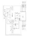
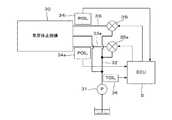
図1は本発明の第1の実施形態にかかる内燃機関及びその制御装置の構成を示す図である。V型6気筒の内燃機関(以下単に「エンジン」という)1は、#1,#2及び#3気筒が設けられた右バンクと、#4,#5及び#6気筒が設けられた左バンクとを備え、右バンクには#1〜#3気筒を一時的に休止させるための気筒休止機構30が設けられている。図2は、気筒休止機構30を油圧駆動するための油圧回路とその制御系を示す図であり、この図も図1と合わせて参照する。Embodiments of the present invention will be described below with reference to the drawings.
FIG. 1 is a diagram showing a configuration of an internal combustion engine and a control device thereof according to a first embodiment of the present invention. A V-type 6-cylinder internal combustion engine (hereinafter simply referred to as “engine”) 1 includes a right bank provided with # 1, # 2 and # 3 cylinders, and a left bank provided with # 4, # 5 and # 6 cylinders. And a
エンジン1の吸気管2の途中にはスロットル弁3が配されている。スロットル弁3には、スロットル弁3の開度THを検出するスロットル弁開度センサ4が設けられており、その検出信号が電子制御ユニット(以下「ECU」という)5に供給される。 A throttle valve 3 is arranged in the middle of the intake pipe 2 of the
燃料噴射弁6は図示しない吸気弁の少し上流側に各気筒毎に設けられており、各噴射弁は図示しない燃料ポンプに接続されていると共にECU5に電気的に接続されて当該ECU5からの信号により燃料噴射弁6の開弁時間が制御される。 A fuel injection valve 6 is provided for each cylinder slightly upstream of an intake valve (not shown). Each injection valve is connected to a fuel pump (not shown) and is electrically connected to the ECU 5 to receive a signal from the ECU 5. Thus, the valve opening time of the fuel injection valve 6 is controlled.
スロットル弁3の直ぐ下流には吸気圧(PBA)センサ7が設けられており、この吸気圧センサ7の検出信号はECU5に供給される。また、吸気圧センサ7の下流には吸気温(TA)センサ8が取付けられており、吸気温TAを検出して対応する電気信号をECU5に供給する。 An intake pressure (PBA) sensor 7 is provided immediately downstream of the throttle valve 3, and a detection signal of the intake pressure sensor 7 is supplied to the ECU 5. An intake air temperature (TA) sensor 8 is attached downstream of the intake pressure sensor 7 to detect the intake air temperature TA and supply a corresponding electric signal to the ECU 5.
エンジン1の本体に装着されたエンジン冷却水温(TW)センサ9はサーミスタ等から成り、エンジン冷却水温TWを検出して対応する温度信号を出力してECU5に供給する。 An engine coolant temperature (TW) sensor 9 mounted on the main body of the
ECU5には、エンジン1のクランク軸(図示せず)の回転角度を検出するクランク角度位置センサ10が接続されており、クランク軸の回転角度に応じた信号がECU5に供給される。クランク角度位置センサ10は、エンジン1の特定の気筒の所定クランク角度位置でパルス(以下「CYLパルス」という)を出力する気筒判別センサ、各気筒の吸入行程開始時の上死点(TDC)に関し所定クランク角度前のクランク角度位置で(6気筒エンジンではクランク角120度毎に)TDCパルスを出力するTDCセンサ及びTDCパルスより短い一定クランク角周期(例えば30度周期)でCRKパルスを発生するCRKセンサから成り、CYLパルス、TDCパルス及びCRKパルスがECU5に供給される。これらの信号パルスは、燃料噴射時期、点火時期等の各種タイミング制御及びエンジン回転数(エンジン回転速度)NEの検出に使用される。 A crank
気筒休止機構30は、エンジン1の潤滑油を作動油として使用し、油圧駆動される。オイルポンプ31により加圧された作動油は、油路32及び吸気側油路33i,排気側油路33eを介して、気筒休止機構30に供給される。油路32と、油路33i及び33eとの間に、吸気側電磁弁35i及び排気側電磁弁35eが設けられており、これらの電磁弁35i,35eはECU5に接続されてその作動がECU5により制御される。 The
油路33i,33eには、作動油圧が所定閾値より低下するとオンする油圧スイッチ34i,34eが設けられており、その検出信号は、ECU5に供給される。また、油路32の途中には、作動油温TOILを検出する作動油温センサ36が設けられており、その検出信号がECU5に供給される。 The
気筒休止機構30の具体的な構成例は、例えば特開平10−103097号公報に示されており、本実施形態でも同様の機構を用いている。この機構によれば、電磁弁35i,35eが閉弁され、油路33i,33e内の作動油圧が低いときは、各気筒(#1〜#3)の吸気弁及び排気弁が通常の開閉作動を行う一方、電磁弁35i,35eが開弁され、油路33i,33e内の作動油圧が高くなると、各気筒(#1〜#3)の吸気弁及び排気弁が閉弁状態を維持する。すなわち、電磁弁35i,35eの閉弁中は、全ての気筒を作動させる全気筒運転が行われ、電磁弁35i,35eを開弁させると、#1〜#3気筒を休止させ、#4〜#6気筒のみ作動させる一部気筒運転が行われる。 A specific configuration example of the
吸気管2のスロットル弁3の下流側と、排気管13との間には、排気還流通路21が設けられており、排気還流通路21の途中には排気還流量を制御する排気還流弁(以下「EGR弁」という)22が設けられている。EGR弁22は、ソレノイドを有する電磁弁であり、その弁開度はECU5により制御される。EGR弁22には、その弁開度(弁リフト量)LACTを検出するリフトセンサ23が設けられており、その検出信号はECU5に供給される。排気還流通路21及びEGR弁22より、排気還流機構が構成される。 An exhaust
エンジン1の各気筒毎に設けられた点火プラグ12は、ECU5に接続されており、点火プラグ12の駆動信号、すなわち点火信号がECU5から供給される。 A
ECU5には大気圧PAを検出する大気圧センサ14、エンジン1により駆動される車両の走行速度(車速)VPを検出する車速センサ15、及び当該車両の変速機のギヤ位置GPを検出するギヤ位置センサ16が接続されており、これらのセンサの検出信号がECU5に供給される。本実施形態では、変速機はロックアップクラッチを備える自動変速機である。 The ECU 5 includes an
ECU5は、各種センサからの入力信号波形を整形し、電圧レベルを所定レベルに修正し、アナログ信号値をデジタル信号値に変換する等の機能を有する入力回路、中央演算処理回路(以下「CPU」という)、CPUで実行される各種演算プログラム及び演算結果等を記憶する記憶回路、前記燃料噴射弁6に駆動信号を供給する出力回路等から構成される。ECU5は、各種センサの検出信号に基づいて、燃料噴射弁6の開弁時間、点火時期及びEGR弁22の開度を制御するとともに、電磁弁35i,35eの開閉を行って、エンジン1の全筒運転と、一部気筒運転との切り換え制御を行う。 The ECU 5 shapes input signal waveforms from various sensors, corrects the voltage level to a predetermined level, converts an analog signal value into a digital signal value, etc., and a central processing circuit (hereinafter referred to as “CPU”). A storage circuit that stores various calculation programs executed by the CPU, calculation results, and the like, an output circuit that supplies a drive signal to the fuel injection valve 6, and the like. The ECU 5 controls the valve opening time, the ignition timing, and the opening degree of the
図3は、一部の気筒を休止させる気筒休止(一部気筒運転)の実行条件を判定する処理のフローチャートである。この処理はECU5のCPUで所定時間(例えば10ミリ秒)毎に実行される。 FIG. 3 is a flowchart of processing for determining execution conditions of cylinder deactivation (partial cylinder operation) for deactivating some cylinders. This process is executed by the CPU of the ECU 5 every predetermined time (for example, 10 milliseconds).
ステップS11では、前条件フラグFCSCNDが「1」であるか否かを判別する。前条件フラグFCSCNDは、作動油温度TOIL、空燃比、エンジン冷却水温TW、大気圧PA、及び外気温が所定範囲内にあり、かつエンジン回転数NEの上限値に関する条件が満たされたとき、「1」に設定される。 In step S11, it is determined whether or not the precondition flag FCSCND is “1”. The precondition flag FCSCND indicates that the hydraulic oil temperature TOIL, the air-fuel ratio, the engine cooling water temperature TW, the atmospheric pressure PA, and the outside air temperature are within predetermined ranges, and the conditions regarding the upper limit value of the engine speed NE are satisfied. 1 ”.
FCSNCD=1であるときは、車速VPが所定下限車速VCS(例えば18km/h)以上であるか否かを判別する(ステップS12)。この答が肯定(YES)であるときは、高負荷運転フラグFWOTが「1」であるか否かを判別する。高負荷運転フラグFWOTは、スロットル弁3をほぼ全開とする所定高負荷運転時に「1」に設定される。 When FCSNCD = 1, it is determined whether or not the vehicle speed VP is equal to or higher than a predetermined lower limit vehicle speed VCS (for example, 18 km / h) (step S12). If the answer is affirmative (YES), it is determined whether or not a high load operation flag FWOT is “1”. The high load operation flag FWOT is set to “1” during a predetermined high load operation in which the throttle valve 3 is almost fully opened.
ステップS11若しくはS12の答が否定(NO)またはステップS13の答が肯定(YES)であるときは、一部気筒運転を行うエンジン運転状態ではない判定し、気筒休止フラグFCSAREAを「0」に設定する(図4,ステップS25)。したがって、全筒運転が実行される。 If the answer to step S11 or S12 is negative (NO) or the answer to step S13 is affirmative (YES), it is determined that the engine is not in an engine operating state in which partial cylinder operation is performed, and the cylinder deactivation flag FCSAREA is set to “0”. (FIG. 4, step S25). Therefore, all-cylinder operation is executed.
ステップS13の答が否定(NO)であるとき、すなわち前条件が成立し、車速VPが所定下限車速VCS以上であり、かつ所定高負荷運転中でないときは、図5に示す下限回転数算出処理を実行し、エンジン回転数NEと比較される下側下限回転数NECSLL及び上側下限回転数NECSLHを算出する(ステップS16)。 When the answer to step S13 is negative (NO), that is, when the precondition is satisfied, the vehicle speed VP is equal to or higher than the predetermined lower limit vehicle speed VCS, and the predetermined high load operation is not being performed, the lower limit rotational speed calculation process shown in FIG. Is executed to calculate the lower lower limit speed NECSLL and the upper lower limit speed NECSLH compared with the engine speed NE (step S16).
ステップS17では、気筒休止フラグFCSAREAが「1」であるか否かを判別する。気筒休止フラグFCSAREAは、エンジン運転状態が一部気筒運転を行うことができる運転領域にあるとき「1」に設定される(図4,ステップS26)。 In step S17, it is determined whether or not the cylinder deactivation flag FCSAREA is “1”. The cylinder deactivation flag FCSAREA is set to “1” when the engine operation state is in an operation region in which partial cylinder operation can be performed (FIG. 4, step S26).
気筒休止フラグFCSAREAが「0」であるときは、エンジン回転数NEが上側下限回転数NECSLH以上であるか否かを判別する(ステップS19)。その答が肯定(YES)であるときはステップS20に進む。また、気筒休止フラグFCSAREAが「1」であるときは、エンジン回転数NEが下側下限回転数NECSLL以上であるか否かを判別する(ステップS18)。その答が肯定(YES)であるときはステップS20に進む。一方、ステップS18またはS19の答が否定(NO)であるときは、ステップS25に進む。 When the cylinder deactivation flag FCSAREA is “0”, it is determined whether or not the engine speed NE is equal to or higher than the upper lower limit speed NECSLH (step S19). If the answer is affirmative (YES), the process proceeds to step S20. When the cylinder deactivation flag FCSAREA is “1”, it is determined whether or not the engine speed NE is equal to or higher than the lower lower limit speed NECSLL (step S18). If the answer is affirmative (YES), the process proceeds to step S20. On the other hand, if the answer to step S18 or S19 is negative (NO), the process proceeds to step S25.
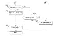
ステップS20では、負荷条件フラグFTHCSが「1」であるか否かを判別する。負荷条件フラグFTHCSは、スロットル弁開度THが所定閾値THCSより小さいとき「1」に設定される。ステップS20の答が肯定(YES)であるときは、ギヤ位置フラグFCSSFTが「1」であるか否かを判別する。ギヤ位置フラグFCSSFTは、ギヤGPに関する条件が成立しているとき「1」に設定される。ステップS20またはS21の答が否定(NO)であるときは、ステップS25に進み、ステップS21の答が肯定(YES)であるときは、ステップS22に進む。 In step S20, it is determined whether or not the load condition flag FTHCS is “1”. The load condition flag FTHCS is set to “1” when the throttle valve opening TH is smaller than the predetermined threshold THCS. If the answer to step S20 is affirmative (YES), it is determined whether or not a gear position flag FCSSFT is “1”. The gear position flag FCSSFT is set to “1” when a condition regarding the gear GP is satisfied. When the answer to step S20 or S21 is negative (NO), the process proceeds to step S25, and when the answer to step S21 is affirmative (YES), the process proceeds to step S22.
ステップS22では、気筒休止フラグFCSAREAが「1」であるか否かを判別する。その答が肯定(YES)であるときは、ダウンカウントタイマTCNCSを所定時間TMCNCS(例えば2秒)にセットしてスタートさせる(ステップS23)とともに、気筒休止フラグFCSAREAを「1」に設定する(ステップS26)。したがって、一部気筒運転が実行される。 In step S22, it is determined whether or not a cylinder deactivation flag FCSAREA is “1”. If the answer is affirmative (YES), the downcount timer TCNCS is set to a predetermined time TMCCS (for example, 2 seconds) and started (step S23), and the cylinder deactivation flag FCSAREA is set to “1” (step) S26). Therefore, partial cylinder operation is performed.
ステップS22でFCSAREA=0であるときは、ダウンカウントタイマTCNCSの値が「0」であるか否かを判別する(ステップS24)。TCNCS>0であるときはステップS25に進み、TCNCS=0となるとステップS26に進む。 If FCSAREA = 0 in step S22, it is determined whether or not the value of the downcount timer TCNCS is “0” (step S24). When TCNCS> 0, the process proceeds to step S25, and when TCNCS = 0, the process proceeds to step S26.
図5は、図3のステップS16で実行される下限回転数算出処理のフローチャートである。
ステップS41では、減速フュエルカットフラグFDECFCが「1」であるか否かを判別する。減速フュエルカットフラグFDECFCは、後述する図7の処理で設定され、エンジンの減速中にフュエルカット運転を実行するとき「1」に設定される。FIG. 5 is a flowchart of the lower limit rotational speed calculation process executed in step S16 of FIG.
In step S41, it is determined whether or not the deceleration fuel cut flag FDECFC is “1”. The deceleration fuel cut flag FDECFC is set in the process of FIG. 7 described later, and is set to “1” when the fuel cut operation is executed during engine deceleration.
FDECFC=0であってフュエルカット運転中でないときは、下側下限回転数NECSLLを通常運転中に適用される所定通常運転回転数NFCTN(例えば1000rpm、ただしエンジン1の負荷となる空調装置の作動中は1500rpm)に設定する(ステップS42)。ステップS46では、下側下限回転数NECSLLに所定加算値DNECS(例えば100rpm)を加算して、上側下限回転数NECSLHを算出する。 When FDECFC = 0 and fuel cut operation is not being performed, the lower limit rotation speed NECSLL is set to a predetermined normal operation speed NFCTN that is applied during normal operation (for example, 1000 rpm, but the air conditioner that is a load on the
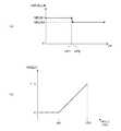
FDECFC=1であってフュエルカット運転中であるときは、車速VPに応じて図6(a)に示すNECSLLBテーブルを検索し、下側下限回転数基本値NECSLLBを算出する(ステップS43)。NECSLLBテーブルは、以下のように設定されている。すなわち、車速VPが第1所定車速VP1(例えば44km/h)より低いときは、下側下限回転数基本値NECSLLBが第1所定回転数NECS1(例えば1100rpm、ただし空調装置作動中は1600rpm)に設定され、車速VPが第2所定車速VP1(例えば46km/h)より高いときは、下側下限回転数基本値NECSLLBが第1所定回転数NECS1より低い第2所定回転数NECS2(例えば1000rpm、ただし空調装置作動中は1500rpm)に設定され、車速VPが第1所定車速VP1以上で第2所定車速VP2以下であるときは、車速VPが増加するほど下側下限回転数基本値NECSLLBが減少するように設定される。 When FDECFC = 1 and the fuel cut operation is being performed, the NECSLLB table shown in FIG. 6A is searched according to the vehicle speed VP, and the lower limit rotational speed basic value NECSLLB is calculated (step S43). The NECSLLB table is set as follows. That is, when the vehicle speed VP is lower than the first predetermined vehicle speed VP1 (for example, 44 km / h), the lower lower limit rotational speed basic value NECSLLB is set to the first predetermined rotational speed NECS1 (for example, 1100 rpm, but 1600 rpm during operation of the air conditioner). When the vehicle speed VP is higher than the second predetermined vehicle speed VP1 (for example, 46 km / h), the lower predetermined lower limit rotational speed basic value NECSLLB is lower than the first predetermined rotation speed NECS1 (for example, 1000 rpm, but air conditioning) When the vehicle speed VP is equal to or higher than the first predetermined vehicle speed VP1 and equal to or lower than the second predetermined vehicle speed VP2, the lower lower limit rotational speed basic value NECSLLB decreases as the vehicle speed VP increases. Is set.
ステップS44では、ロックアップクラッチの係合度合RELCに応じて図6(b)に示すKRELCテーブルを検索し、補正係数KRELCを算出する。KRELCテーブルは、係合度合RELCが90%以下であるときは補正係数KRELCが「0」となり、係合度合RELCが90%より高いときは、係合度合RELCが増加するほど補正係数KRELCが増加するように設定されている。なお、係合度合RELCは、車速VP、ギヤ位置GP及びエンジン回転数NEに応じて算出される。 In step S44, the KRELC table shown in FIG. 6B is searched according to the engagement degree RELC of the lockup clutch, and the correction coefficient KRELC is calculated. In the KRELC table, when the engagement degree RELC is 90% or less, the correction coefficient KRELC is “0”, and when the engagement degree RELC is higher than 90%, the correction coefficient KRELC increases as the engagement degree RELC increases. It is set to be. The engagement degree RELC is calculated according to the vehicle speed VP, the gear position GP, and the engine speed NE.
ステップS45では、下記式(1)に下側下限回転数基本値NECSLLB及び補正係数KRELCを適用し、下側下限回転数NECSLLを算出する。
NECSLL=(NECSLLB−NECS2)×KRELC+NECS2
(1)In step S45, the lower limit rotational speed NECSLL is calculated by applying the lower limit rotational speed basic value NECSLLB and the correction coefficient KRELC to the following equation (1).
NECSLL = (NECSLLB−NECS2) × KRELC + NECS2
(1)
式(1)によれば、係合度合RELCが90%より高いときは、係合度合RELCが増加するほど、下側下限回転数NECSLLが増加するように設定され、係合度合RELCが90%以下であるときは、下側下限回転数NECSLLは第2所定回転数NECS2に設定される。
ステップS45実行後はステップS46に進み、上側下限回転数NECSLHを算出する。According to the equation (1), when the engagement degree RELC is higher than 90%, the lower lower limit rotational speed NECSLL is set to increase as the engagement degree RELC increases, and the engagement degree RELC is 90%. When it is below, the lower limit rotational speed NECSLL is set to the second predetermined rotational speed NECS2.
After execution of step S45, the process proceeds to step S46, and the upper lower limit rotational speed NECSLH is calculated.
図5の処理によれば、一部気筒運転を許可するか否かを判定するための閾値である下限回転数(下側及び上側下限回転数)NECSLL,NECSLHは、フュエルカット運転を実行しているか否か及び車速VPに応じて設定される。フュエルカット運転を実行しており、かつ振動が発生し易い車速であるときに、下限回転数NECSLL,NECSLHを高めて全筒運転への移行を早めることにより、減速運転中における不快な車体振動を防止することができる。 According to the process of FIG. 5, the lower limit rotational speeds (lower and upper lower limit rotational speeds) NECSLL and NECSLH, which are threshold values for determining whether or not to permit partial cylinder operation, execute the fuel cut operation. It is set according to whether or not and the vehicle speed VP. When fuel cut operation is being performed and the vehicle speed is likely to generate vibration, the lower limit speeds NECSLL and NECSLH are increased to accelerate the transition to all-cylinder operation, thereby reducing unpleasant vehicle body vibration during deceleration operation. Can be prevented.
また、ロックアップクラッチの係合度合RELCに応じて設定される補正係数KRELCにより下限回転数NECSLL,NECSLHが補正される。ロックアップクラッチの係合度合RELCが低いときは、エンジンの出力トルク変動が発生しても車体振動は発生しないので、係合度合RECLが低くなるほど下限回転数NECSLL,NECSLHを低下させることにより、一部気筒運転を実行する運転領域を広げることができる。 Further, the lower limit rotational speeds NECSLL and NECSLH are corrected by a correction coefficient KRELC set according to the engagement degree RELC of the lockup clutch. When the engagement degree RELC of the lockup clutch is low, vehicle body vibration does not occur even if engine output torque fluctuations occur. Therefore, as the engagement degree RECL decreases, the lower limit rotational speeds NECSLL and NECSLH are reduced. The operation area in which the partial cylinder operation is executed can be expanded.
図7は、図5の処理で参照される減速フュエルカットフラグFDECFCの設定処理のフローチャートである。この処理は所定時間(例えば10ミリ秒)毎にECU5のCPUで実行される。 FIG. 7 is a flowchart of the deceleration fuel cut flag FDECFC setting process referred to in the process of FIG. This process is executed by the CPU of the ECU 5 every predetermined time (for example, 10 milliseconds).
ステップS51では、全閉フラグFTHFCOKが「1」であるか否かを判別する。全閉フラグFTHFCOKはスロットル弁3が全閉状態とき「1」に設定される。この答が肯定(YES)であるときは、全閉減速フラグFTHDECが「1」であるか否かを判別する。全閉減速フラグFTHDECは、スロットル弁3が全閉状態にあり、かつエンジンが減速中であるとき「1」に設定される。 In step S51, it is determined whether or not the fully closed flag FTHFCOK is “1”. The fully closed flag FTHFCOK is set to “1” when the throttle valve 3 is fully closed. If the answer is affirmative (YES), it is determined whether or not a fully closed deceleration flag FTHDEC is “1”. The fully closed deceleration flag FTHDEC is set to “1” when the throttle valve 3 is in the fully closed state and the engine is decelerating.
ステップS51でFTHFCOKが「0」であるとき、またはステップS52でFTHDECが「0」であるときは、吸気圧フラグFPBFCが「1」であるか否かを判別する(ステップS58)。吸気圧フラグFPBFCは、吸気圧PBAが所定圧PBTHL(例えば17.3kPa(130mmHg))以下であるとき「1」に設定される。ステップS58の答が否定(NO)であるときは、エンジン1が所定急減速状態にないと判定し、ステップS61に進み、急減速フラグFDECFCCNを「0」に設定する。 When FTHFCOK is “0” in step S51, or when FTHDEC is “0” in step S52, it is determined whether or not the intake pressure flag FPBFC is “1” (step S58). The intake pressure flag FPBFC is set to “1” when the intake pressure PBA is equal to or lower than a predetermined pressure PBTHL (for example, 17.3 kPa (130 mmHg)). If the answer to step S58 is negative (NO), it is determined that the
ステップS58でFPBFC=1であって吸気圧PBAが所定圧PBTHL以下であるときは、減速フュエルカットフラグFDECFCが「1」であるか否かを判別する(ステップS59)。この答が肯定(YES)であるときは、直ちにステップS63に進む。FDECFC=0であるときは、吸気圧変化量DPBACYLの絶対値が所定変化量DPBDLY(例えば1.6kPa(12mmHg))以上であるか否かを判別する(ステップS60)。吸気圧変化量DPBACYLは、吸気圧PBAの今回値PBA(k)と前回値PBA(k-1)の差(PBA(k)−PBA(k-1))として算出される。 If FPBFC = 1 in step S58 and the intake pressure PBA is equal to or lower than the predetermined pressure PBTHL, it is determined whether or not the deceleration fuel cut flag FDECFC is “1” (step S59). If the answer is affirmative (YES), the process immediately proceeds to step S63. When FDECFC = 0, it is determined whether or not the absolute value of the intake pressure change amount DPBACYL is equal to or greater than a predetermined change amount DPBDLY (for example, 1.6 kPa (12 mmHg)) (step S60). The intake pressure change amount DPBACYL is calculated as a difference between the current value PBA (k) and the previous value PBA (k-1) of the intake pressure PBA (PBA (k) -PBA (k-1)).
ステップS60の答が肯定(YES)であって、吸気圧PBAの変化が比較的大きいときは、エンジン1が所定急減速状態にないと判定し、前記ステップS61に進む。|DPBACYL|<DPBDLYであるときは、エンジン1が所定急減速状態にあると判定し、急減速フラグFDECFCCNを「1」に設定する(ステップS62)。ステップS61またはS62実行後は、ステップS63に進む。 If the answer to step S60 is affirmative (YES) and the change in the intake pressure PBA is relatively large, it is determined that the
一方ステップS52でFTHDEC=1であるときは、回転数フラグFNFCTが「1」であるか否かを判別する(ステップS53)。この答が肯定(YES)であって、エンジン回転数NEが比較的高いときは、エンジン回転数NEが下側フュエルカット回転数NEFCL(例えば950rpm、ただし空調装置の作動中は1450rpm)より低いか否かを判別する(ステップS54)。この答が肯定(YES)であるときは、回転数フラグFNFCTを「0」に設定し(ステップS55)、前記ステップS61に進む。またステップS54でNE≧NEFCLであるときは、前記ステップS59に進む。 On the other hand, if FTHDEC = 1 in step S52, it is determined whether or not the rotation speed flag FNFCT is “1” (step S53). If this answer is affirmative (YES) and the engine speed NE is relatively high, is the engine speed NE lower than the lower fuel cut speed NEFCL (for example, 950 rpm, but 1450 rpm when the air conditioner is in operation)? It is determined whether or not (step S54). If the answer is affirmative (YES), the rotational speed flag FNFCT is set to “0” (step S55), and the process proceeds to step S61. If NE ≧ NEFCL in step S54, the process proceeds to step S59.
ステップS53でFNFCT=0であって、エンジン回転数NEが比較的低いときは、エンジン回転数NEが上側フュエルカット回転数NEFCH(下側フュエルカット回転数NEFCLより例えば100rpm高い回転数に設定される)以上であるか否かを判別する。この答が肯定(YES)であるときは、回転数フラグFNFCTを「1」に設定し(ステップS57)、前記ステップS59に進む。またステップS56でNE<NEFCHであるときは、エンジン1が所定急減速状態ではないと判定し、前記ステップS61に進む。 If FNFCT = 0 in step S53 and the engine speed NE is relatively low, the engine speed NE is set to an upper fuel cut speed NEFCH (for example, 100 rpm higher than the lower fuel cut speed NEFCL). ) It is determined whether or not it is above. If the answer is affirmative (YES), the engine speed flag FNFCT is set to “1” (step S57), and the process proceeds to step S59. If NE <NEFCH in step S56, it is determined that the
ステップS63では、急減速フラグFDECFCCNが「1」であるか否かを判別し、その答が否定(NO)であるときは、減速フュエルカットフラグFDECFCを「0」に設定する。したがって、フュエルカット運転は実行されない。 In step S63, it is determined whether or not the rapid deceleration flag FDECCFCN is "1". If the answer is negative (NO), the deceleration fuel cut flag FDECFC is set to "0". Therefore, the fuel cut operation is not executed.
一方、FDECFCCN=1であるときは、遅延フラグFTFCDLYが「1」であるか否かを判別する。遅延フラグFTFCDLYは、フュエルカット運転の開始時期を所定時間TFCDLY(例えば0.5秒)だけ遅らせるために用いられるフラグであり、急減速フラグFDECFCCNが「0」から「1」に変化した時点から所定時間TFCDLYが経過するまで「1」に設定される。 On the other hand, when FDECCFCN = 1, it is determined whether or not the delay flag FTFCDLY is “1”. The delay flag FTFCDLY is a flag used to delay the start time of the fuel cut operation by a predetermined time TFCDLY (for example, 0.5 seconds), and is predetermined from the time when the rapid deceleration flag FDECCFCN changes from “0” to “1”. It is set to “1” until the time TFCDLY elapses.
ステップS64の答が肯定(YES)であるときは、前記ステップS65に進み、FTFCDLY=0となるとステップS66に進み、減速フュエルカットフラグFDECFCを「1」に設定する。したがって、フュエルカット運転が実行される。 If the answer to step S64 is affirmative (YES), the process proceeds to step S65, and if FTFCDLY = 0, the process proceeds to step S66, and the deceleration fuel cut flag FDECFC is set to “1”. Therefore, the fuel cut operation is executed.
下側フュエルカット回転数NEFCLは、フュエルカット運転を実行中の下側下限回転数NECSLLの最小値(=NEFCS2)より低く設定されており、一部気筒運転及びフュエルカット運転を実行中にエンジン回転数NEが徐々に低下していくときは、先ず一部気筒運転から全筒運転に移行し、その後フュエルカット運転を終了する(燃料供給を再開する)。 The lower fuel cut speed NEFCL is set lower than the minimum value (= NEFCS2) of the lower lower limit speed NECSLL during the fuel cut operation, and the engine speed during the partial cylinder operation and the fuel cut operation is performed. When the number NE gradually decreases, the operation first shifts from the partial cylinder operation to the all cylinder operation, and then ends the fuel cut operation (restarts the fuel supply).
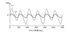
図8は、フュエルカット運転中におけるエンジン出力トルクTRQの変化の一例(エンジン回転数NE=1200rpm)を示す図であり、破線L1が一部気筒運転に対応し、実線L2が全筒運転に対応する。この図から明らかなように一部気筒運転中の方が、トルク変動が大きくなるため、フュエルカット運転中は、通常運転中に比べてより高い回転数で一部気筒運転から全筒運転へ移行することにより、フュエルカット運転中の不快な車体振動を防止することができる。 FIG. 8 is a diagram showing an example of a change in the engine output torque TRQ (engine speed NE = 1200 rpm) during the fuel cut operation, where the broken line L1 corresponds to the partial cylinder operation, and the solid line L2 corresponds to the all cylinder operation. To do. As is clear from this figure, the torque fluctuation is larger during partial cylinder operation, so during fuel cut operation, transition from partial cylinder operation to full cylinder operation is performed at a higher rotational speed than during normal operation. By doing so, unpleasant vehicle body vibration during the fuel cut operation can be prevented.
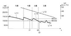
図9は、制御動作例を説明するためのタイムチャートである。実線L11及びL12は、それぞえエンジン回転数NE及び車速VPの推移を示す。また破線L13は、ロックアップクラッチの係合度合RECLが100%である場合の下側下限回転数NECSLLを示し、実線L14は係合度合RECLが90%以下である場合の下側下限回転数NECSLLを示す。図9に示される減速運転においては、当初ギヤ位置GPが5速にあり、フュエルカット運転及び一部気筒運転が行われており、車速VPの低下に伴ってシフトダウンが行われる。ロックアップクラッチの係合度合RECLが100%であるときは、時刻t1においてエンジン回転数NEが下側下限回転数NECSLLに達するため、一部気筒運転から全筒運転へ移行する。その後時刻t3において、フュエルカット運転を終了する。また係合度合RECLが90%以下であるときは、時刻t2においてエンジン回転数NEが下側下限回転数NECSLLに達するため、一部気筒運転から全筒運転へ移行する。係合度合RECLが90%と100%の間にあるときは、時刻t1より後で時刻t2より前に一部気筒運転から全筒運転への移行が行われる。このように係合度合RECLが高いほどより高いエンジン回転数NEで一部気筒運転から全筒運転への移行を行うことにより、不快な車体振動を確実に防止することができる。 FIG. 9 is a time chart for explaining an example of the control operation. Solid lines L11 and L12 indicate changes in the engine speed NE and the vehicle speed VP, respectively. A broken line L13 indicates a lower lower limit rotational speed NECSLL when the engagement degree RECL of the lockup clutch is 100%, and a solid line L14 indicates a lower lower limit rotational speed NECSLL when the engagement degree RECL is 90% or less. Indicates. In the deceleration operation shown in FIG. 9, the initial gear position GP is at the fifth speed, the fuel cut operation and the partial cylinder operation are performed, and the downshift is performed as the vehicle speed VP decreases. When the engagement degree RECL of the lockup clutch is 100%, the engine speed NE reaches the lower lower limit speed NECSLL at time t1, and therefore, the operation shifts from the partial cylinder operation to the all cylinder operation. Thereafter, at time t3, the fuel cut operation is terminated. When the degree of engagement RECL is 90% or less, the engine speed NE reaches the lower lower limit speed NECSLL at time t2, so that the operation shifts from partial cylinder operation to all cylinder operation. When the degree of engagement RECL is between 90% and 100%, the transition from the partial cylinder operation to the all cylinder operation is performed after time t1 and before time t2. As described above, the higher the degree of engagement RECL, the higher the engine speed NE and the transition from partial cylinder operation to all cylinder operation can reliably prevent unpleasant vehicle body vibration.
本実施形態では、気筒休止機構30が切換手段に相当し、クランク角度位置センサ10及び車速センサ15が回転数検出手段及び車速検出手段に相当する。またECU5がフュエルカット運転実行手段、一部気筒運転許可手段、下限回転数設定手段、及び補正手段を構成する。具体的には、図7の処理がフュエルカット運転実行手段に相当し、図3のステップS17〜S19,S26が一部気筒運転許可手段に相当し、図5の処理が下限回転数設定手段に相当し、図5のステップS44及びS45が補正手段に相当する。 In the present embodiment, the
なお本発明は上述した実施形態に限るものではなく、種々の変形が可能である。例えば、車速センサ15の故障が検出されたときは、通常は一部気筒運転を禁止するが、エンジン回転数NE及びギヤ位置GPに応じて一部気筒運転を許可するようにしてもよい。すなわち、車速センサ15の故障が検出されたときは、図3のステップS12の判別を行わないようにし、さらに下限回転数算出処理を図5の処理に代えて、図10に示す処理を適用する。 The present invention is not limited to the embodiment described above, and various modifications can be made. For example, when a failure of the
図10の処理は、図5のステップS43をステップS43aに代えたものである。ステップS43aでは、ギヤ位置GPに応じて下側下限回転数基本値NECSLLBの設定を行う。例えば、ギヤ位置GPが5速または4速であるときは、下側下限回転数基本値NECSLLBを第2所定回転数NECS2に設定し、ギヤ位置GPが3速〜1速であるときは、下側下限回転数基本値NECSLLBを第1所定回転数NECS1に設定する。 The process in FIG. 10 is obtained by replacing step S43 in FIG. 5 with step S43a. In step S43a, the lower limit rotational speed basic value NECSLLB is set according to the gear position GP. For example, when the gear position GP is 5th speed or 4th speed, the lower lower limit rotational speed basic value NECSLLB is set to the second predetermined rotational speed NECS2, and when the gear position GP is 3rd speed to 1st speed, The lower limit rotational speed basic value NECSLLB is set to the first predetermined rotational speed NECS1.
この変形例では、一部気筒運転の許可判定に適用する下限回転数NECSLLを、減速フュエルカットを実行しているか否か(減速フュエルカットフラグFDECFC)及びギヤ位置GPに応じて設定するようにしたので、車速センサ15の故障時においても不快な車体振動を防止することができる。 In this modification, the lower limit rotational speed NECSLL applied to the permission determination for partial cylinder operation is set according to whether or not the deceleration fuel cut is being executed (deceleration fuel cut flag FDECFC) and the gear position GP. Therefore, unpleasant vehicle body vibration can be prevented even when the
なお、車速センサ15が故障していないときでも、図10の処理により、下限回転数NECSLLを設定するようにしてもよい。 Even when the
1 内燃機関
5 電子制御ユニット(フュエルカット運転実行手段、一部気筒運転許可手段、下限回転数設定手段)
10 クランク角度位置センサ(回転数検出手段)
15 車速センサ(車速検出手段)
16 ギヤ位置センサ(ギヤ位置検出手段)
30 気筒休止機構(切換手段)1 Internal combustion engine 5 Electronic control unit (fuel cut operation execution means, partial cylinder operation permission means, lower limit rotational speed setting means)
10 Crank angle position sensor (rotational speed detection means)
15 Vehicle speed sensor (vehicle speed detection means)
16 Gear position sensor (Gear position detection means)
30 cylinder deactivation mechanism (switching means)
Claims (3)
Translated fromJapanese前記機関の回転数を検出する回転数検出手段と、
前記機関により駆動される車両の車速を検出する車速検出手段と、
前記機関の減速中に前記機関への燃料供給を遮断するフュエルカット運転を行うフュエルカット運転実行手段と、
検出した機関回転数が下限回転数以上であるとき、前記一部気筒運転を許可する一部気筒運転許可手段と、
前記フュエルカット運転を実行しているか否か及び前記車速に応じて、前記下限回転数を設定する下限回転数設定手段とを備えることを特徴とする内燃機関の制御装置。All-cylinder operation having a plurality of cylinders and operating all of the plurality of cylinders,and partial cylinder operation for stoppingthe operation ofsome cylinders by stopping the operation ofintake valves of some cylinders of the plurality of cylinders In a control device for an internal combustion engine provided with switching means for switching between
A rotational speed detecting means for detecting the rotational speed of the engine;
Vehicle speed detection means for detecting the vehicle speed of the vehicle driven by the engine;
A fuel cut operation execution means for performing a fuel cut operation for shutting off fuel supply to the engine during deceleration of the engine;
A partial cylinder operation permission means for permitting the partial cylinder operation when the detected engine rotational speed is equal to or greater than a lower limit rotational speed;
A control apparatus for an internal combustion engine, comprising: a lower limit rotational speed setting means for setting the lower limit rotational speed according to whether or not the fuel cut operation is being performed and the vehicle speed.
前記下限回転数設定手段は、前記車速検出手段の故障が検出されたときは、前記フュエルカット運転を実行しているか否か及び前記ギヤ位置に応じて、前記下限回転数を設定することを特徴とする請求項1または2に記載の内燃機関の制御装置。Further comprising a gear position detecting means for detecting a gear position of the transmissionprior SLengine,
The lower limit rotational speed setting means, when a failure of the vehicle speed detecting means is detected, the depending on whether or not and the gear position is running fuel cut operation, andTurkey set the lower limit rotation speed The control device foran internal combustion engine according toclaim 1 , wherein the control device isan internal combustion engine.
Priority Applications (1)
| Application Number | Priority Date | Filing Date | Title |
|---|---|---|---|
| JP2007227294AJP4884337B2 (en) | 2007-09-03 | 2007-09-03 | Control device for internal combustion engine |
Applications Claiming Priority (1)
| Application Number | Priority Date | Filing Date | Title |
|---|---|---|---|
| JP2007227294AJP4884337B2 (en) | 2007-09-03 | 2007-09-03 | Control device for internal combustion engine |
Publications (2)
| Publication Number | Publication Date |
|---|---|
| JP2009057932A JP2009057932A (en) | 2009-03-19 |
| JP4884337B2true JP4884337B2 (en) | 2012-02-29 |
Family
ID=40553885
Family Applications (1)
| Application Number | Title | Priority Date | Filing Date |
|---|---|---|---|
| JP2007227294AExpired - Fee RelatedJP4884337B2 (en) | 2007-09-03 | 2007-09-03 | Control device for internal combustion engine |
Country Status (1)
| Country | Link |
|---|---|
| JP (1) | JP4884337B2 (en) |
Families Citing this family (1)
| Publication number | Priority date | Publication date | Assignee | Title |
|---|---|---|---|---|
| JP6551445B2 (en)* | 2017-03-29 | 2019-07-31 | マツダ株式会社 | Engine control device |
Family Cites Families (5)
| Publication number | Priority date | Publication date | Assignee | Title |
|---|---|---|---|---|
| JP2600429B2 (en)* | 1990-03-28 | 1997-04-16 | 日産自動車株式会社 | Integrated control system for engine and automatic transmission |
| JP3039289B2 (en)* | 1994-09-14 | 2000-05-08 | トヨタ自動車株式会社 | Integrated control unit for engine and automatic transmission |
| JP3760545B2 (en)* | 1996-03-29 | 2006-03-29 | マツダ株式会社 | Control device for automatic transmission |
| JP2003054291A (en)* | 2001-08-17 | 2003-02-26 | Toyota Motor Corp | Vehicle integrated control device |
| JP4302565B2 (en)* | 2004-04-02 | 2009-07-29 | 本田技研工業株式会社 | Control device for internal combustion engine |
- 2007
- 2007-09-03JPJP2007227294Apatent/JP4884337B2/ennot_activeExpired - Fee Related
Also Published As
| Publication number | Publication date |
|---|---|
| JP2009057932A (en) | 2009-03-19 |
Similar Documents
| Publication | Publication Date | Title |
|---|---|---|
| US7509201B2 (en) | Sensor feedback control for noise and vibration | |
| US7934485B2 (en) | Internal combustion engine control device | |
| US20110208411A1 (en) | Stop control system for internal combustion engine | |
| KR100740478B1 (en) | Controller of internal combustion engine | |
| JP4326844B2 (en) | Control device for internal combustion engine | |
| JP4080372B2 (en) | Control device for internal combustion engine | |
| JP2011256774A (en) | Apparatus to control internal combustion engine | |
| JP3583324B2 (en) | Control device for internal combustion engine | |
| JP5305043B2 (en) | Engine combustion state detection device | |
| JP4884337B2 (en) | Control device for internal combustion engine | |
| JP4279717B2 (en) | Control device for internal combustion engine | |
| JP4120614B2 (en) | Start control device for internal combustion engine | |
| JP5566429B2 (en) | Control device for internal combustion engine | |
| JP4101715B2 (en) | Control device for internal combustion engine | |
| JPH09310627A (en) | Torque down control device for automatic transmission | |
| JP4656984B2 (en) | Control device for internal combustion engine | |
| JP2004100528A (en) | Ignition timing control device for internal combustion engine | |
| JP4020205B2 (en) | Internal combustion engine control device | |
| JP3760549B2 (en) | Variable intake control system for internal combustion engine | |
| JP4574699B2 (en) | Control device for internal combustion engine | |
| JP4302565B2 (en) | Control device for internal combustion engine | |
| JP2013117206A (en) | Device for controlling internal combustion engine for vehicle | |
| JP2008202524A (en) | Internal combustion engine | |
| JP4811305B2 (en) | Automatic stop device for vehicle engine | |
| JP2005282394A (en) | Fuel supply control device for internal combustion engine |
Legal Events
| Date | Code | Title | Description |
|---|---|---|---|
| A621 | Written request for application examination | Free format text:JAPANESE INTERMEDIATE CODE: A621 Effective date:20091127 | |
| A977 | Report on retrieval | Free format text:JAPANESE INTERMEDIATE CODE: A971007 Effective date:20110324 | |
| A131 | Notification of reasons for refusal | Free format text:JAPANESE INTERMEDIATE CODE: A131 Effective date:20110329 | |
| A521 | Written amendment | Free format text:JAPANESE INTERMEDIATE CODE: A523 Effective date:20110518 | |
| TRDD | Decision of grant or rejection written | ||
| A01 | Written decision to grant a patent or to grant a registration (utility model) | Free format text:JAPANESE INTERMEDIATE CODE: A01 Effective date:20111129 | |
| A01 | Written decision to grant a patent or to grant a registration (utility model) | Free format text:JAPANESE INTERMEDIATE CODE: A01 | |
| A61 | First payment of annual fees (during grant procedure) | Free format text:JAPANESE INTERMEDIATE CODE: A61 Effective date:20111206 | |
| FPAY | Renewal fee payment (event date is renewal date of database) | Free format text:PAYMENT UNTIL: 20141216 Year of fee payment:3 | |
| R150 | Certificate of patent or registration of utility model | Ref document number:4884337 Country of ref document:JP Free format text:JAPANESE INTERMEDIATE CODE: R150 Free format text:JAPANESE INTERMEDIATE CODE: R150 | |
| R250 | Receipt of annual fees | Free format text:JAPANESE INTERMEDIATE CODE: R250 | |
| LAPS | Cancellation because of no payment of annual fees |