JP4883246B2 - Object detection apparatus and object detection method - Google Patents
Object detection apparatus and object detection methodDownload PDFInfo
- Publication number
- JP4883246B2 JP4883246B2JP2011507732AJP2011507732AJP4883246B2JP 4883246 B2JP4883246 B2JP 4883246B2JP 2011507732 AJP2011507732 AJP 2011507732AJP 2011507732 AJP2011507732 AJP 2011507732AJP 4883246 B2JP4883246 B2JP 4883246B2
- Authority
- JP
- Japan
- Prior art keywords
- edge
- target
- reliability
- object detection
- deriving
- Prior art date
- Legal status (The legal status is an assumption and is not a legal conclusion. Google has not performed a legal analysis and makes no representation as to the accuracy of the status listed.)
- Active
Links
Images


Classifications
- G—PHYSICS
- G01—MEASURING; TESTING
- G01S—RADIO DIRECTION-FINDING; RADIO NAVIGATION; DETERMINING DISTANCE OR VELOCITY BY USE OF RADIO WAVES; LOCATING OR PRESENCE-DETECTING BY USE OF THE REFLECTION OR RERADIATION OF RADIO WAVES; ANALOGOUS ARRANGEMENTS USING OTHER WAVES
- G01S13/00—Systems using the reflection or reradiation of radio waves, e.g. radar systems; Analogous systems using reflection or reradiation of waves whose nature or wavelength is irrelevant or unspecified
- G01S13/88—Radar or analogous systems specially adapted for specific applications
- G01S13/93—Radar or analogous systems specially adapted for specific applications for anti-collision purposes
- G01S13/931—Radar or analogous systems specially adapted for specific applications for anti-collision purposes of land vehicles
- G—PHYSICS
- G01—MEASURING; TESTING
- G01S—RADIO DIRECTION-FINDING; RADIO NAVIGATION; DETERMINING DISTANCE OR VELOCITY BY USE OF RADIO WAVES; LOCATING OR PRESENCE-DETECTING BY USE OF THE REFLECTION OR RERADIATION OF RADIO WAVES; ANALOGOUS ARRANGEMENTS USING OTHER WAVES
- G01S13/00—Systems using the reflection or reradiation of radio waves, e.g. radar systems; Analogous systems using reflection or reradiation of waves whose nature or wavelength is irrelevant or unspecified
- G01S13/86—Combinations of radar systems with non-radar systems, e.g. sonar, direction finder
- G01S13/867—Combination of radar systems with cameras
- G—PHYSICS
- G08—SIGNALLING
- G08G—TRAFFIC CONTROL SYSTEMS
- G08G1/00—Traffic control systems for road vehicles
- G08G1/16—Anti-collision systems
- G08G1/166—Anti-collision systems for active traffic, e.g. moving vehicles, pedestrians, bikes
- B—PERFORMING OPERATIONS; TRANSPORTING
- B60—VEHICLES IN GENERAL
- B60R—VEHICLES, VEHICLE FITTINGS, OR VEHICLE PARTS, NOT OTHERWISE PROVIDED FOR
- B60R21/00—Arrangements or fittings on vehicles for protecting or preventing injuries to occupants or pedestrians in case of accidents or other traffic risks
- B60R21/01—Electrical circuits for triggering passive safety arrangements, e.g. airbags, safety belt tighteners, in case of vehicle accidents or impending vehicle accidents
- B60R21/013—Electrical circuits for triggering passive safety arrangements, e.g. airbags, safety belt tighteners, in case of vehicle accidents or impending vehicle accidents including means for detecting collisions, impending collisions or roll-over
- B60R21/0134—Electrical circuits for triggering passive safety arrangements, e.g. airbags, safety belt tighteners, in case of vehicle accidents or impending vehicle accidents including means for detecting collisions, impending collisions or roll-over responsive to imminent contact with an obstacle, e.g. using radar systems
- G—PHYSICS
- G01—MEASURING; TESTING
- G01S—RADIO DIRECTION-FINDING; RADIO NAVIGATION; DETERMINING DISTANCE OR VELOCITY BY USE OF RADIO WAVES; LOCATING OR PRESENCE-DETECTING BY USE OF THE REFLECTION OR RERADIATION OF RADIO WAVES; ANALOGOUS ARRANGEMENTS USING OTHER WAVES
- G01S13/00—Systems using the reflection or reradiation of radio waves, e.g. radar systems; Analogous systems using reflection or reradiation of waves whose nature or wavelength is irrelevant or unspecified
- G01S13/88—Radar or analogous systems specially adapted for specific applications
- G01S13/93—Radar or analogous systems specially adapted for specific applications for anti-collision purposes
- G01S13/931—Radar or analogous systems specially adapted for specific applications for anti-collision purposes of land vehicles
- G01S2013/932—Radar or analogous systems specially adapted for specific applications for anti-collision purposes of land vehicles using own vehicle data, e.g. ground speed, steering wheel direction
- G—PHYSICS
- G01—MEASURING; TESTING
- G01S—RADIO DIRECTION-FINDING; RADIO NAVIGATION; DETERMINING DISTANCE OR VELOCITY BY USE OF RADIO WAVES; LOCATING OR PRESENCE-DETECTING BY USE OF THE REFLECTION OR RERADIATION OF RADIO WAVES; ANALOGOUS ARRANGEMENTS USING OTHER WAVES
- G01S13/00—Systems using the reflection or reradiation of radio waves, e.g. radar systems; Analogous systems using reflection or reradiation of waves whose nature or wavelength is irrelevant or unspecified
- G01S13/88—Radar or analogous systems specially adapted for specific applications
- G01S13/93—Radar or analogous systems specially adapted for specific applications for anti-collision purposes
- G01S13/931—Radar or analogous systems specially adapted for specific applications for anti-collision purposes of land vehicles
- G01S2013/9327—Sensor installation details
- G01S2013/93271—Sensor installation details in the front of the vehicles
Landscapes
- Engineering & Computer Science (AREA)
- Radar, Positioning & Navigation (AREA)
- Remote Sensing (AREA)
- Physics & Mathematics (AREA)
- General Physics & Mathematics (AREA)
- Computer Networks & Wireless Communication (AREA)
- Electromagnetism (AREA)
- Traffic Control Systems (AREA)
- Radar Systems Or Details Thereof (AREA)
- Closed-Circuit Television Systems (AREA)
Description
Translated fromJapanese本発明は、レーダ及び画像センサによって取得される情報に基づいて物体を検出する物体検出装置及び物体検出方法に関する。 The present invention relates to an object detection apparatus and an object detection method for detecting an object based on information acquired by a radar and an image sensor.
近年、PCS(Pre-crash safety system)等の衝突回避又は衝突による被害の低減のための安全システムが開発されている。このような安全システムを好適に実現させるためには、自車両以外の車両や歩行者等の障害物の位置及び大きさ、並びに該障害物と自車との距離等を正確に把握する必要がある。これらを把握するための技術として、レーダ及びステレオ画像センサを用いた物体検出装置が知られている。 In recent years, safety systems such as PCS (Pre-crash safety system) have been developed for avoiding collisions or reducing damage caused by collisions. In order to suitably realize such a safety system, it is necessary to accurately grasp the position and size of obstacles such as vehicles and pedestrians other than the own vehicle, and the distance between the obstacle and the own vehicle. is there. As a technique for grasping these, an object detection device using a radar and a stereo image sensor is known.
レーダによれば、電磁波の反射点として物標(検出対象となる物体)を認識することができ、これによって、物標の位置を取得することができる。しかしながら、レーダでは物標のエッジを正確に取得することが困難である。一方、ステレオ画像センサによって撮像された画像からは物標のエッジを高精度で取得することができる。そこで、上記物体検出装置においては、レーダによって取得される物標情報と、ステレオ画像センサによって撮像された画像から取得される物標情報とをフュージョンさせる。これによって、物体検出装置の物体検出能力を向上させることができる。 According to the radar, a target (an object to be detected) can be recognized as an electromagnetic wave reflection point, and thereby the position of the target can be acquired. However, it is difficult for the radar to accurately acquire the edge of the target. On the other hand, the edge of the target can be acquired with high accuracy from the image captured by the stereo image sensor. Therefore, in the object detection device, the target information acquired by the radar and the target information acquired from the image captured by the stereo image sensor are fused. Thereby, the object detection capability of the object detection device can be improved.
しかしながら、画像センサとしてステレオ画像センサを使用すると、ステレオ画像センサを設置するために比較的大きいスペースを確保する必要が生じ、さらに、物体検出装置を実現させるためのコストも比較的高くなる。そのため、ステレオ画像センサに代えて単眼画像センサを用いて、ステレオ画像センサを用いた場合と同様の機能及び性能を有する物体検出装置を実現することが望まれている。 However, when a stereo image sensor is used as the image sensor, it is necessary to secure a relatively large space for installing the stereo image sensor, and the cost for realizing the object detection device is also relatively high. Therefore, it is desired to realize an object detection device having the same function and performance as when a stereo image sensor is used by using a monocular image sensor instead of the stereo image sensor.
特許文献1には、ミリ波レーダと単眼カメラとを使用した車両用障害物認識装置が開示されている。該車両用障害物認識装置は、物体情報演算手段、画像処理手段及び車両情報取得手段を備えている。物体情報演算手段は、ミリ波レーダの出力から検出物体との相対距離及び相対横位置等の物体情報を演算する。画像処理手段は、物体情報演算手段による演算結果に基づき、単眼カメラによって撮像された画像を処理する。そして、該車両用障害物認識装置は、少なくとも物体情報演算手段及び車両情報取得手段の出力に基づいて検出物体が障害物となる可能性を判定する。さらに、画像処理手段の出力が障害物の判定に有効であるか否かを物体情報演算手段による演算結果に基づいて判定し、有効な場合にのみ画像処理手段の出力も障害物の判定に用いる。
特許文献2には、カメラとレーダとから画像情報と距離情報とを取得する物体検出装置が開示されている。該物体検出装置では、画像情報からエッジの方向ベクトル、エッジの方向ベクトル分散、エッジ強度及びエッジ強度分散を算出する。そして、これらのうちの少なくとも1つと検出対象物体との距離とに基づいて対象物の種類を判定する。
物体検出装置において、画像センサとして単眼画像センサを用いた場合、省スペース化及び低コスト化を図ることができる。しかしながら、単眼画像センサによって撮像された画像からは正確な奥行き方向の情報を取得することが困難である。そのため、単眼画像センサによって撮像された画像から物標の左右のエッジを検出した場合、実際には自車両から見て該物標よりも奥に存在する物体又は模様のエッジが、該物標のエッジとして誤検出される場合がある。このように誤検出されたエッジに基づいて該物標の横方向の位置(横位置)を導出すると、該物標の横位置も誤検出する虞がある。 In the object detection device, when a monocular image sensor is used as the image sensor, space saving and cost reduction can be achieved. However, it is difficult to acquire accurate information in the depth direction from an image captured by a monocular image sensor. Therefore, when the left and right edges of a target are detected from an image captured by a monocular image sensor, the edge of an object or pattern that exists behind the target as viewed from the host vehicle is actually In some cases, it is erroneously detected as an edge. If the lateral position (lateral position) of the target is derived based on the erroneously detected edge as described above, the lateral position of the target may be erroneously detected.
本発明は、上記のような問題に鑑みてなされたものであって、レーダによって取得される物標情報と単眼画像センサによって撮像された画像から取得される物標情報とに基づいて物体を検出する物体検出装置において、物標の横位置の検出精度をより向上させることが可能な技術を提供することを目的とする。 The present invention has been made in view of the above problems, and detects an object based on target information acquired by a radar and target information acquired from an image captured by a monocular image sensor. An object of the present invention is to provide a technique capable of further improving the detection accuracy of the lateral position of a target.
本発明では、単眼画像センサによって撮像された画像から物標の右側エッジ及び左側エッジを取得する。さらに、右側エッジ及び左側エッジの軌跡を近似する直線又は所定の曲線である軌跡近似線を両エッジについて導出する。そして、右側エッジ及び左側エッジのうち軌跡近似線上に存在するエッジの数が多い方を物標の真のエッジとして選択し、選択された方のエッジの位置に基づいて物標の横位置を導出する。 In the present invention, the right edge and the left edge of the target are acquired from the image captured by the monocular image sensor. Furthermore, a straight line approximating the trajectory of the right edge and the left edge or a trajectory approximate line which is a predetermined curve is derived for both edges. Then, select the right edge or left edge that has more edges on the locus approximation line as the true edge of the target, and derive the lateral position of the target based on the position of the selected edge. To do.
より詳しくは、第一の発明に係る物体検出装置は、
レーダによって取得される物標情報と単眼画像センサによって撮像された画像から取得される物標情報とに基づいて物体を検出する物体検出装置であって、
前記レーダによって認識された物標に相当する物標を前記単眼画像センサによって撮像された画像から抽出するとともに、該抽出された物標の右側エッジ及び左側エッジを取得するエッジ取得手段と、
前記エッジ取得手段によって取得された右側エッジ及び左側エッジの軌跡を近似する直線又は所定の曲線である軌跡近似線を両エッジについて導出する軌跡近似線導出手段と、
前記エッジ取得手段によって取得された右側エッジ及び左側エッジのうち前記軌跡近似線上に存在するエッジの数が多い方を物標の真のエッジとして選択する選択手段と、
前記選択手段によって真のエッジとして選択された方のエッジの位置に基づいて物標の横位置を導出する横位置導出手段と、
を備えたことを特徴とする 。More specifically, the object detection device according to the first invention is
An object detection device that detects an object based on target information acquired by a radar and target information acquired from an image captured by a monocular image sensor,
An edge acquisition means for extracting a target corresponding to the target recognized by the radar from an image captured by the monocular image sensor, and acquiring a right edge and a left edge of the extracted target;
Trajectory approximate line deriving means for deriving a trajectory approximate line that is a straight line or a predetermined curve that approximates the trajectory of the right edge and the left edge acquired by the edge acquiring means, for both edges;
A selection unit that selects, as a true edge of a target, a larger number of edges existing on the locus approximate line among the right edge and the left edge acquired by the edge acquisition unit;
Lateral position deriving means for deriving the lateral position of the target based on the position of the edge selected as the true edge by the selecting means;
It is characterized by having.
本発明によれば、単眼画像センサによって撮像された画像から取得された物標の右側エッジ及び左側エッジのうち信頼度の高い方のエッジが物標の真のエッジとして選択される。そして、信頼度の高い方のエッジの位置に基づいて物標の横位置が導出される。従って、物標の横位置の検出精度をより向上させることができる。 According to the present invention, the edge having the higher reliability among the right edge and the left edge of the target acquired from the image captured by the monocular image sensor is selected as the true edge of the target. Then, the lateral position of the target is derived based on the position of the edge with the higher reliability. Therefore, the detection accuracy of the lateral position of the target can be further improved.
本発明に係る物体検出装置は、エッジ取得手段によって取得された右側エッジ及び左側エッジに対し信頼度の重み付けを行なう重み付け手段をさらに備えてもよい。この場合、重み付け手段は、右側エッジ及び左側エッジに対し、レーダによって認識された物標の位置からより近い方の信頼度がより高くなるように重み付けを行なう。さらに、本発明に係る物体検出装置は、重み付け手段によって重み付けられた信頼度を右側エッジ及び左側エッジそれぞれについて複数分合計することで両エッジについての信頼度の合計値を算出する信頼度合計値算出手段を備えてもよい。 The object detection apparatus according to the present invention may further include weighting means for weighting reliability on the right edge and the left edge acquired by the edge acquisition means. In this case, the weighting unit weights the right edge and the left edge so that the reliability closer to the position of the target recognized by the radar is higher. Furthermore, the object detection apparatus according to the present invention calculates a reliability total value for calculating a total value of reliability for both edges by adding a plurality of reliability weighted by the weighting means for each of the right edge and the left edge. Means may be provided.
本発明においては、右側エッジと左側エッジとで軌跡近似線上に存在するエッジの数が同数となる場合がある。この場合、選択手段は、右側エッジ及び左側エッジのうち、信頼度合計値算出手段によって算出された信頼度の合計値が大きい方を、物標の真のエッジとして選択してもよい。 In the present invention, the right edge and the left edge may have the same number of edges on the locus approximation line. In this case, the selection unit may select, as the true edge of the target, the larger of the reliability total values calculated by the reliability total value calculation unit among the right edge and the left edge.
これによっても、物標の右側エッジ及び左側エッジのうち信頼度の高い方のエッジを物標の真のエッジとして選択することができる。 This also makes it possible to select the edge having the higher reliability of the right edge and the left edge of the target as the true edge of the target.
本発明においては、横位置導出手段は、軌跡予測手段と衝突位置予測手段とを有してもよい。軌跡予測手段は、選択手段によって真のエッジとして選択された方のエッジの今後の軌跡を予測する。衝突位置予測手段は、軌跡予測手段によってよって予測された今後のエッジの軌跡に基づいて、該エッジと車両との前後方向の距離が零となる位置として、物標と車両との衝突位置を予測する。この場合、横位置導出手段は、衝突位置予測手段によって予測された衝突位置における、選択手段によって真のエッジとして選択された方のエッジの位置に基づいて、該衝突位置における物標の横方向の中心(以下、物標中心と称する)の横位置を導出してもよい。 In the present invention, the lateral position deriving unit may include a trajectory predicting unit and a collision position predicting unit. The trajectory predicting means predicts the future trajectory of the edge selected as the true edge by the selecting means. The collision position prediction means predicts the collision position between the target and the vehicle based on the future edge trajectory predicted by the trajectory prediction means as the position where the distance in the front-rear direction between the edge and the vehicle becomes zero. To do. In this case, the lateral position deriving means determines the lateral position of the target at the collision position based on the position of the edge selected as the true edge by the selection means at the collision position predicted by the collision position prediction means. The lateral position of the center (hereinafter referred to as the target center) may be derived.
これによれば、物標と車両との衝突位置における物標中心の横位置を検出することができる。 According to this, the lateral position of the target center at the collision position between the target and the vehicle can be detected.
本発明に係る物標検出装置においては、横位置導出手段が、物標の横幅を推定する横幅推定手段を有してもよい。この場合、横位置導出手段は、選択手段によって真のエッジとして選択された方のエッジの位置から、横幅推定手段によって推定された物標の横幅の1/2分他方のエッジ側にずれた位置を物標中心の横位置として導出してもよい。 In the target detection apparatus according to the present invention, the lateral position deriving unit may include a lateral width estimating unit that estimates the lateral width of the target. In this case, the lateral position deriving means shifts from the position of the edge selected as the true edge by the selecting means to the other edge side by 1/2 of the lateral width of the target estimated by the lateral width estimating means. May be derived as the lateral position of the target center.
これによれば、物標中心の横位置を高精度で検出することができる。 According to this, the lateral position of the target center can be detected with high accuracy.
また、第二の発明に係る物体検出方法は、
レーダによって取得される物標情報と単眼画像センサによって撮像された画像から取得される物標情報とに基づいて物体を検出する物体検出方法であって、
前記レーダによって認識された物標に相当する物標を前記単眼画像センサによって撮像された画像から抽出するとともに、該抽出された物標の右側エッジ及び左側エッジを取得するエッジ取得工程と、
前記エッジ取得工程において取得された右側エッジ及び左側エッジの軌跡を近似する直線又は所定の曲線である軌跡近似線を両エッジについて導出する軌跡近似線導出工程と、
前記エッジ取得工程において取得された右側エッジ及び左側エッジのうち前記軌跡近似線上に存在するエッジの数が多い方を物標の真のエッジとして選択する選択工程と、
前記選択工程において真のエッジとして選択された方のエッジの位置に基づいて物標の横位置を導出する横位置導出工程と、
を有することを特徴とする。An object detection method according to the second invention is
An object detection method for detecting an object based on target information acquired by a radar and target information acquired from an image captured by a monocular image sensor,
Extracting a target corresponding to the target recognized by the radar from an image captured by the monocular image sensor, and acquiring a right edge and a left edge of the extracted target; and
A locus approximation line deriving step for deriving a locus approximation line that is a straight line or a predetermined curve that approximates the locus of the right edge and the left edge acquired in the edge acquisition step for both edges;
A selection step of selecting, as the true edge of the target, the one having the larger number of edges existing on the locus approximate line among the right edge and the left edge acquired in the edge acquisition step;
A lateral position deriving step of deriving the lateral position of the target based on the position of the edge selected as the true edge in the selection step;
It is characterized by having.
本発明においても、信頼度の高い方のエッジの位置に基づいて物標の横位置が導出される。従って、物標の横位置の検出精度をより向上させることができる。 Also in the present invention, the lateral position of the target is derived based on the position of the edge with the higher reliability. Therefore, the detection accuracy of the lateral position of the target can be further improved.
本発明に係る物体検出方法は、エッジ取得工程において取得された右側エッジ及び左側エッジに対し信頼度の重み付けを行なう重み付け工程をさらに有してもよい。この場合、重み付け工程では、右側エッジ及び左側エッジに対し、レーダによって認識された物標の位置からより近い方の信頼度がより高くなるように重み付けを行なう。さらに、本発明に係る物体検出方法は、重み付け工程において重み付けられた信頼度を右側エッジ及び左側エッジそれぞれについて複数分合計することで両エッジについての信頼度の合計値を算出する信頼度合計値算出工程を有してもよい。 The object detection method according to the present invention may further include a weighting step of weighting reliability on the right edge and the left edge acquired in the edge acquisition step. In this case, in the weighting step, the right edge and the left edge are weighted so that the reliability closer to the position of the target recognized by the radar is higher. Furthermore, the object detection method according to the present invention calculates a reliability total value for calculating a total value of reliability for both edges by summing a plurality of reliability values weighted in the weighting step for each of the right edge and the left edge. You may have a process.
そして、本発明において、右側エッジ及び左側エッジとで軌跡近似線上に存在するエッジの数が同数のときは、選択工程において、信頼度合計値算出工程において算出された信頼度の合計値が大きい方を、物標の真のエッジとして選択してもよい。 In the present invention, when the right edge and the left edge have the same number of edges existing on the locus approximation line, in the selection process, the larger of the reliability total values calculated in the reliability total value calculation process May be selected as the true edge of the target.
これにより、物標の右側エッジ及び左側エッジのうち信頼度の高い方のエッジを物標の真のエッジとして選択することができる。 As a result, it is possible to select the edge having the higher reliability of the right edge and the left edge of the target as the true edge of the target.
尚、第一及び第二の発明において、「軌跡近似線上に存在するエッジ」には、軌跡近似線と完全に一致する位置に存在するエッジのみならず、軌跡近似線から予め定められた許容範囲内に位置するエッジが含まれてもよい。 In the first and second aspects of the invention, the “edge existing on the locus approximate line” includes not only an edge existing at a position that completely coincides with the locus approximate line but also an allowable range determined in advance from the locus approximate line. Edges located within may be included.
本発明によれば、レーダによって取得される物標情報と単眼画像センサによって撮像された画像から取得される物標情報とに基づいて物体を検出する物体検出装置において、物標の横位置の検出精度をより向上させることができる。 According to the present invention, in an object detection device that detects an object based on target information acquired by a radar and target information acquired from an image captured by a monocular image sensor, the lateral position of the target is detected. The accuracy can be further improved.
以下、本発明の具体的な実施形態について図面に基づいて説明する。本実施例に記載されている構成部品の寸法、材質、形状、その相対配置等は、特に記載がない限りは発明の技術的範囲をそれらのみに限定する趣旨のものではない。 Hereinafter, specific embodiments of the present invention will be described with reference to the drawings. The dimensions, materials, shapes, relative arrangements, and the like of the components described in the present embodiment are not intended to limit the technical scope of the invention to those unless otherwise specified.
<実施例1>
本発明の実施例1について図1〜9に基づいて説明する。<Example 1>
A first embodiment of the present invention will be described with reference to FIGS.
(概略構成)
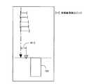
ここでは、本発明を衝突予測装置に適用した場合について説明する。図1及び2は、本実施例に係る衝突予測装置の概略構成を示すブロック図である。衝突予測装置200は、車両100に搭載されており、他車両や歩行者等の障害物と自車両100との衝突を予測する装置である。また、車両100には、該衝突予測装置200の他、障害物との衝突が予測されたときに作動する警告装置8及び衝突回避・衝突被害低減システム9が搭載されている。(Outline configuration)
Here, a case where the present invention is applied to a collision prediction apparatus will be described. 1 and 2 are block diagrams illustrating a schematic configuration of a collision prediction apparatus according to the present embodiment. The
衝突予測装置200は、ミリ波レーダ1、単眼画像センサ2、操舵角センサ3、ヨーレートセンサ4、車輪パルスセンサ5及びECU10を備えている。ミリ波レーダ1は、車両100の前側中央部に取り付けられている。ミリ波レーダ1は、車両100の前方及び斜め前方をミリ波帯の電磁波によって水平方向にスキャンすると共に車外の物体の表面で反射された電磁波を受信する。これにより、ミリ波レーダ1は物標を電磁波の反射点として認識する。そして、ミリ波の送受信データから得られた物標情報(自車両100に対する物標の相対位置等)がECU10に入力される。 The
単眼画像センサ2は、車両100の前側中央部に取り付けられている。単眼画像センサ2は、車両100の前方及び斜め前方の画像を撮像する。撮像された画像は画像信号としてECU10に入力される。 The
操舵角センサ3は、車両100のステアリングロッド等に取り付けられており、運転者が操作したステアリングホイールの操舵角を検出する。ヨーレートセンサ4は、車両100の車体の中央位置に設けられており、車体にかかるヨーレートを検出する。車輪パルスセンサ5は、車両100のホイール部分に取り付けられており、車両の車輪速度を検出する。これらのセンサの出力信号がECU10に入力される。 The
ECU10は、物体検出部6及び衝突判定部7を有している。物体検出部6は、ミリ波レーダ1によって取得された物標情報と単眼画像センサ2によって撮像された画像から取得される物標情報とに基づいて障害物を検出する。衝突判定部7は、物体検出部6によって検出された障害物と自車両100とが衝突するか否かを判定する。物体検出部6における物体検出方法及び衝突判定部7における衝突判定方法の詳細については後述する。 The
図2は、本実施例に係る物体検出部6の概略構成を示すブロック図である。図2(a)に示すように、物体検出部6は、エッジ検出部61、軌跡近似線導出部62、選択部63及び横位置導出部64を有している。また、図2(b)に示すように、横位置導出部64は、軌跡予測部641、衝突位置予測部642、横幅推定部643及び物標中心横位置導出部644を有している。各部61〜64及び641〜644の詳細については後述する。 FIG. 2 is a block diagram illustrating a schematic configuration of the object detection unit 6 according to the present embodiment. As illustrated in FIG. 2A, the object detection unit 6 includes an
ECU10は、さらに、推定カーブ半径演算部、自車速度演算部、自車軌道演算部、障害物速演算部及び障害物移動距離演算部等(図示略)の、衝突判定部での衝突判定のために必要となる各種パラメータを算出する演算部を有している。例えば、推定カーブ半径演算部は、操舵角センサ3から入力された操舵角信号およびヨーレートセンサ4から入力されたヨーレート信号に基いて、自車両100の推定カーブ半径を算出する。自車速演算部は、車輪パルスセンサ5から入力された車輪速度信号に基いて、自車両100の車速を算出する。自車軌道演算部は、推定カーブ半径演算部から入力された推定カーブ半径信号に基いて、自車両100の軌道を算出する。障害物速演算部は、物体検出部6によって検出された障害物の移動速度をその物標情報に基づいて算出する。障害物移動距離演算部は、物体検出部6によって検出された障害物の検出後の移動距離をその物標情報に基づいて算出する。 The
衝突判定部7によって障害物と衝突すると判定された場合、ECU10から警告装置8及び衝突回避・衝突被害低減システム9にON信号が送信される。警告装置8は、該ON信号を受信すると、モニタへの表示や音声等による運転者への警告を実行する。衝突回避・衝突被害低減システムは、該ON信号を受信すると、衝突回避制御や衝突被害低減制御を実行する。衝突回避・衝突被害低減システムとしては、自動操舵システム、シートベルト制御システム、シート位置制御システム及びブレーキ制御システム及びエアバッグ制御システム等を例示することができる。 When the collision determination unit 7 determines that the vehicle collides with the obstacle, an ON signal is transmitted from the
(横位置導出方法)
衝突予測装置200におけるECU10の物体検出部6は、衝突判定部7における衝突判定に用いるための障害物の横位置を導出する。以下、本実施例に係る障害物の横位置導出方法について図3〜7に基づいて説明する。(Horizontal position derivation method)
The object detection unit 6 of the
上述したように、物体検出部6は、ミリ波レーダ1によって取得された物標情報と単眼画像センサ2によって撮像された画像から取得される物標情報とに基づいて障害物を検出する。ミリ波レーダ1によれば、自車両100に対する物標の相対位置を検出することができる。しかしながら、ミリ波レーダ1では、物標のエッジを高精度で検出することが困難である。そこで、本実施例では、単眼画像センサ2によって撮像された画像を用いて物標のエッジを検出する。 As described above, the object detection unit 6 detects an obstacle based on the target information acquired by the
より詳しくは、物体検出部6のエッジ検出部61において、ミリ波レーダ1によって認識された物標に相当する物標、即ち、ミリ波レーダ1によって検出された物標の位置(以下、ミリ波検出位置と称する場合もある)に存在する物標を単眼画像センサ2によって撮像された画像から抽出する。さらに、抽出された物標の画像から該物標の右側エッジ及び左側エッジを検出する(以下、該エッジを単眼画像検出エッジと称する場合もある)。 More specifically, the
しかしながら、単眼画像センサ2によって撮像された画像からは正確な奥行き方向の情報(距離)を取得することが困難である。そのため、単眼画像センサ2によって撮像された画像から物標の左右のエッジを検出した場合、実際には自車両100から見て該物標よりも奥に存在する物体又は模様のエッジが該物標のエッジとして誤検出される場合がある。 However, it is difficult to obtain accurate information (distance) in the depth direction from the image captured by the
図3は、単眼画像センサによって撮像された画像におけるミリ波検出位置と単眼画像検出エッジとを示す図である。図3(a)は、物標のエッジが正常に検出された場合を示しており、図3(b)は、物標のエッジが誤検出された場合を示している。尚、図3(a)及び(b)においては、物標を「手前の電柱」とする。図3(b)に示すように、単眼画像センサによって撮像された画像からエッジを検出した場合、「奥の電柱」のエッジが「手前の電柱」のエッジとして誤検出される場合がある。 FIG. 3 is a diagram illustrating a millimeter wave detection position and a monocular image detection edge in an image captured by the monocular image sensor. FIG. 3A shows a case where the edge of the target is normally detected, and FIG. 3B shows a case where the edge of the target is erroneously detected. In FIGS. 3A and 3B, the target is “front pole”. As illustrated in FIG. 3B, when an edge is detected from an image captured by a monocular image sensor, an edge of “back utility pole” may be erroneously detected as an edge of “front power pole”.
ここで、本実施例とは異なり、ミリ波レーダとステレオ画像センサとを用いて障害物を検出した場合の検出結果について図4に基づいて説明する。この場合においても、ミリ波検出位置に存在する物標をステレオ画像センサによって撮像された画像から抽出する。そして、抽出された物標の画像から該物標の右側エッジ及び左側エッジを検出する(以下、これらのエッジをステレオ画像検出エッジと称する場合もある)。図4は、「手前の電柱」を物標とした場合のミリ波検出位置及びステレオ画像検出エッジの自車両に対する時間的な位置の変化を示す図である。尚、図4において、t=n+1の図は、t=nから50ms後の様子を示している。また、t=4の図において、白抜き矢印は、ミリ波検出位置及びステレオ画像検出エッジに基づいて導出された物標の軌跡を表している。 Here, unlike the present embodiment, a detection result when an obstacle is detected using a millimeter wave radar and a stereo image sensor will be described with reference to FIG. Even in this case, the target existing at the millimeter wave detection position is extracted from the image captured by the stereo image sensor. Then, the right edge and left edge of the target are detected from the extracted target image (hereinafter, these edges may be referred to as stereo image detection edges). FIG. 4 is a diagram illustrating temporal changes in the millimeter wave detection position and the stereo image detection edge with respect to the host vehicle when the “front utility pole” is the target. In FIG. 4, t = n + 1 shows a state 50 ms after t = n. In the figure at t = 4, the white arrow represents the trajectory of the target derived based on the millimeter wave detection position and the stereo image detection edge.
ステレオ画像センサによって撮像された画像からは正確な奥行き方向の情報を取得することができる。そのため、単眼画像センサによって撮像された画像からエッジを検出した場合、「手前の電柱」よりも奥に「奥の電柱」が存在しても、図4に示すように、「奥の電柱」のエッジを「手前の電柱」のエッジとして誤検出することがない。 Accurate information in the depth direction can be acquired from the image captured by the stereo image sensor. Therefore, when an edge is detected from an image captured by a monocular image sensor, even if there is a “back utility pole” behind the “front power pole”, as shown in FIG. The edge is not erroneously detected as the edge of the “front pole”.
従って、ステレオ画像検出エッジに基づいて物標中心の横位置を高精度で導出することができる。そのため、t=4の図に示すように、ミリ波検出位置及びステレオ画像検出エッジに基づいて物標の軌跡を高精度で導出することができる。その結果、今後の物標の軌跡も高精度で予測することが可能となる。 Therefore, the lateral position of the target center can be derived with high accuracy based on the stereo image detection edge. Therefore, as shown in the diagram at t = 4, the trajectory of the target can be derived with high accuracy based on the millimeter wave detection position and the stereo image detection edge. As a result, the trajectory of the future target can be predicted with high accuracy.
一方、本実施例のように、ミリ波レーダと単眼画像センサとを用いて障害物を検出した場合の検出結果について図5に基づいて説明する。図5は、「手前の電柱」を物標とした場合のミリ波検出位置及び単眼画像検出エッジの自車両に対する時間的な位置の変化を示す図である。尚、図5においては、図4と同様、t=n+1の図がt=nから50ms後の様子を示している。また、t=5の図において、白抜き矢印は、ミリ波検出位置及び単眼画像検出エッジに基づいて導出された物標の軌跡を表している。 On the other hand, a detection result when an obstacle is detected using a millimeter wave radar and a monocular image sensor as in this embodiment will be described with reference to FIG. FIG. 5 is a diagram illustrating temporal changes in the millimeter wave detection position and the monocular image detection edge with respect to the host vehicle when the “electric pole in front” is the target. In FIG. 5, similarly to FIG. 4, the diagram of t = n + 1 shows a state after 50 ms from t = n. In the figure at t = 5, the white arrow represents the trajectory of the target derived based on the millimeter wave detection position and the monocular image detection edge.
上述したように、単眼画像センサによって撮像された画像からエッジを検出すると、「奥の電柱」のエッジを「手前の電柱」のエッジとして誤検出する場合がある。従って、単眼画像検出エッジに基づいて物標中心の横位置を高精度で導出することは困難である。そのため、ミリ波検出位置及び単眼画像検出エッジに基づいて物標の軌跡を導出した場合、t=5の図に示すように、該軌跡を誤って導出する場合がある。このような場合、今後の物標の軌跡を高精度で予測することも困難となる。 As described above, when an edge is detected from an image captured by a monocular image sensor, the edge of the “back utility pole” may be erroneously detected as the edge of the “front pole”. Therefore, it is difficult to derive the lateral position of the target center with high accuracy based on the monocular image detection edge. Therefore, when the trajectory of the target is derived based on the millimeter wave detection position and the monocular image detection edge, the trajectory may be erroneously derived as shown in the diagram at t = 5. In such a case, it is difficult to predict the trajectory of the future target with high accuracy.
誤って予測された物標の軌跡に基づいて衝突判定部7における該物標と自車両100との衝突判定が行なわれると、誤判定を招く虞がある。そこで、本実施例では、物体検出部6において、衝突判定部7における衝突判定に用いるための物標の横位置を導出するために、単眼画像センサ2によって撮像された画像に対し以下のような横位置導出処理を行なう。尚、図6及び7は、本実施例に係る横位置導出処理のイメージを示す図である。 If a collision determination between the target and the
本実施例に係る横位置導出処理では、物体検出部6の軌跡近似線導出部62において、図6に示すように、エッジ検出部61によって所定時間毎(本実施例では50ms毎)に検出された複数の単眼画像検出エッジについて、右側エッジ及び左側エッジそれぞれの軌跡を近似する直線又は所定の曲線である軌跡近似線を導出する。図6(a)及び(b)はいずれも図5において検出された単眼画像検出エッジを示している。図6(a)における一転鎖線が、左側エッジについて導出された軌跡近似線を示しており、図6(b)における一転鎖線が、右側エッジについて導出された軌跡近似線を示している。尚、軌跡近似線を導出する方法は予め定められている。ここでは、最小二乗法やスプライン補間法等、既知のどのような方法を用いてもよい。「所定の曲線」とは、予め定められた近似方法で導出される曲線を意味する。 In the lateral position deriving process according to the present embodiment, the locus approximate
ここで、図6(a)に示すように、左側エッジは全て正常に検出されているため、5点のエッジ全てが軌跡近似線上に存在している。一方、図6(b)に示すように、右側エッジには誤検出されたエッジが含まれているため、5点のエッジ中、軌跡近似線上に存在するのは3点のみである。尚、ここでは、軌跡近似線と完全に一致する位置になくとも該軌跡近似線から予め定められた許容範囲内に存在するエッジは、軌跡近似線上に存在するものとしてカウントする。図6(a)及び(b)においては、丸で囲んだエッジが、「軌跡近似線上に存在するエッジ」を示している。 Here, as shown in FIG. 6 (a), since all the left edges are detected normally, all the five edges exist on the locus approximation line. On the other hand, as shown in FIG. 6B, the right edge includes an erroneously detected edge, and therefore, of the five points, only three points exist on the locus approximation line. Note that, here, an edge that exists within a predetermined allowable range from the locus approximate line even if it is not at a position that completely coincides with the locus approximate line is counted as existing on the locus approximate line. In FIGS. 6A and 6B, the circled edges indicate “edges existing on the locus approximate line”.
つまり、軌跡近似線上に存在するエッジの数が多い方のエッジは、軌跡近似線上に存在するエッジの数が少ない方のエッジに比べて信頼度が高いと判断できる。そこで、選択部63においては、軌跡近似線上に存在するエッジの数に基づいて右側エッジ及び左側エッジの信頼度を算出する。そして、右側エッジ及び左側エッジのうち信頼度の高い方(即ち、軌跡近似線上に存在するエッジの数が多い方(図6では左側エッジ))を物標の真のエッジとして選択する。 That is, it can be determined that the edge having the larger number of edges existing on the locus approximate line has higher reliability than the edge having the smaller number of edges existing on the locus approximate line. Therefore, the
そして、横位置導出部64において、選択部63で物標の真のエッジとして選択された方のエッジ(以下、選択エッジと称する場合もある)の位置に基づいて物標の横位置を導出する。より詳しくは、図7に示すように、先ず、軌跡予測部641において、選択エッジ(図7では左側エッジ)の今後の軌跡をこれまでの軌跡近似線に基づいて予測する。図7においては、一転鎖線で示す矢印が、選択エッジのこれまでの軌跡近似線及び予測される今後の軌跡を表している。 Then, the lateral
次に、衝突位置予測部642において、軌跡予測部641で予測された選択エッジの今後の軌跡とECU10の自車両軌道演算部において算出された自車両100の軌道に基づいて、選択エッジと自車両100との前後方向の距離が零となる位置として、物標と自車両100との衝突位置を予測する。図7においては、破線が衝突位置を表している。 Next, in the collision
さらに、横位置導出部64では、横幅推定部643において、物標の横幅Wtを推定する。ここで、横幅推定方法としては、既知のどのような方法を用いてもよい。具体的には、単眼画像検出エッジから導出される物標の横幅の平均値を物標の横幅Wtとして算出する方法や、ミリ波レーダ1における受信波の強度から推定される物標の種類に基づいて物標の横幅Wtを導出する方法等を例示することができる。 Further, in the lateral
そして、物標中心横位置導出部644において、衝突位置予測部642で予測された衝突位置における物標中心の横位置を導出する。具体的には、衝突位置における選択エッジの位置から、横幅推定部643で推定された物標の横幅Wtの1/2分他方のエッジ(図7では右側エッジ)側にずれた位置を、衝突位置における物標中心の横位置として導出する。図7においては、白抜き三角で示す位置が衝突位置における物標中心の横位置を表している。 Then, the target center lateral
上記のような横位置導出方法によれば、単眼画像検出エッジにおける右側エッジ及び左側エッジのうち信頼度の高い方のエッジが物標の真のエッジとして選択される。そして、信頼度の高い方のエッジの位置に基づいて、衝突位置における物標中心の横位置が導出される。従って、画像センサとして単眼画像センサを用いた場合であっても、衝突位置における物標中心の横位置を高精度で導出することができる。 According to the lateral position deriving method as described above, the edge having the higher reliability of the right edge and the left edge in the monocular image detection edge is selected as the true edge of the target. Then, based on the position of the edge having the higher reliability, the lateral position of the target center at the collision position is derived. Therefore, even when a monocular image sensor is used as the image sensor, the lateral position of the target center at the collision position can be derived with high accuracy.
そして、衝突判定部7においては、物体検出部6において導出された衝突位置における物標中心の横位置に基づいて衝突判定を実行する。これにより、自車両100と障害物とが衝突するか否かをより高精度で判定することが可能となる。 Then, the collision determination unit 7 performs the collision determination based on the lateral position of the target center at the collision position derived by the object detection unit 6. Thereby, it becomes possible to determine with high accuracy whether or not the
(衝突判定フロー)
本実施例に係る自車両と障害物との衝突判定のフローについて図8及び9に示すフローチャートに基づいて説明する。本フローは、ECU10によって所定の間隔で繰り返し実行される。(Collision judgment flow)
A collision determination flow between the host vehicle and the obstacle according to the present embodiment will be described with reference to flowcharts shown in FIGS. This flow is repeatedly executed by the
本フローでは、先ずステップS101において、単眼画像センサ2によって撮像された画像からミリ波検出位置に存在する物標が抽出される。 In this flow, first, in step S101, a target existing at a millimeter wave detection position is extracted from an image captured by the
次に、ステップS102において、ステップS101で抽出された物標の画像から右側エッジ及び左側エッジが検出される。尚、ステップS101及びステップS102の処理はエッジ検出部61によって実行される。 Next, in step S102, the right edge and the left edge are detected from the target image extracted in step S101. Note that the processing of steps S101 and S102 is executed by the
次に、ステップS103において、ステップS102で検出された複数の単眼画像検出エッジについて、右側エッジ及び左側エッジそれぞれの軌跡近似線が導出される。尚、ステップS103の処理は軌跡近似線導出部62によって実行される。 Next, in step S103, locus approximation lines for the right edge and the left edge are derived for the plurality of monocular image detection edges detected in step S102. The process of step S103 is executed by the locus approximate
次に、ステップS104において、ステップS103で導出された軌跡近似線上に存在するエッジの数に基づいて右側エッジ及び左側エッジの信頼度が算出される。 Next, in step S104, the reliability of the right edge and the left edge is calculated based on the number of edges existing on the locus approximation line derived in step S103.
次に、ステップS105において、右側エッジ及び左側エッジのうち、ステップS104で算出された信頼度の高い方のエッジが、物標の真のエッジとして選択される。尚、ステップS104及びS105の処理は選択部63によって実行される。 Next, in step S105, of the right edge and the left edge, the edge having the higher reliability calculated in step S104 is selected as the true edge of the target. Note that the processing of steps S104 and S105 is executed by the
次に、ステップS106において、ステップS105で選択された選択エッジの今後の軌跡が予測される。尚、ステップS106の処理は軌跡予測部641によって実行される。 Next, in step S106, the future trajectory of the selected edge selected in step S105 is predicted. Note that the process of step S106 is executed by the
次に、ステップS107において、ステップS106で予測された選択エッジの今後の軌跡と自車両軌道演算部において算出された自車両100の軌道に基づいて、物標と自車両100との衝突位置が予測される。尚、ステップS107の処理は衝突位置予測部642によって実行される。 Next, in step S107, the collision position between the target and the
次に、ステップS108において、物標の横幅Wtが推定される。尚、ステップS108の処理は横幅推定部643によって実行される。 Next, in step S108, the lateral width Wt of the target is estimated. Note that the processing in step S108 is executed by the lateral
次に、ステップS109において、ステップS107で予測された衝突位置における選択エッジの位置から、ステップS108で推定された物標の横幅Wtの1/2分他方のエッジ側にずれた位置が、衝突位置における物標中心の横位置として導出される。尚、ステップS109の処理は物標中心横位置導出部644によって実行される。 Next, in step S109, the position shifted from the position of the selected edge at the collision position predicted in step S107 to the other edge side by ½ of the lateral width Wt of the target estimated in step S108 is the collision position. Derived as the lateral position of the target center at. Note that the processing in step S109 is executed by the target center lateral
次に、ステップS110において、ステップS109で導出された衝突位置における物標中心の横位置に基づいて、該物標と自車両100との衝突確率Pcが算出される。 Next, in step S110, the collision probability Pc between the target and the
次に、ステップS111において、ステップS110で算出された衝突確率Pcが基準確率Pcbase以上であるか否かが判別される。ここで、基準確率Pcbaseは、物標と自車両100とが衝突すると判定すべき閾値として予め設定された値である。 Next, in step S111, it is determined whether or not the collision probability Pc calculated in step S110 is greater than or equal to the reference probability Pcbase. Here, the reference probability Pcbase is a value set in advance as a threshold value to be determined that the target and the
ステップS111において、肯定判定された場合、次にステップS112において、物標と自車両100とが衝突すると判定される。一方、ステップS111において、否定判定された場合、次にステップS113において、物標と自車両100とは衝突しないと判定される。尚、ステップS110〜S113の処理は衝突判定部7によって実行される。そして、ステップS112において物標と自車両100とが衝突すると判定された場合、衝突判定部7は、警告装置8及び衝突回避・衝突被害低減システム9にON信号を送信する。 If an affirmative determination is made in step S111, it is then determined in step S112 that the target and the
(本実施例の構成要素と本発明の構成要件との関係)
尚、本実施例においては、物体検出部6が本発明に係る物体検出装置に相当する。また、本実施例に係る物体検出部6の構成要素と本発明の構成要件との関係は次のとおりである。エッジ検出部61が本発明に係るエッジ取得手段に相当する。軌跡近似線導出部62が本発明に係る軌跡近似線導出手段に相当する。選択部63が本発明に係る選択手段に相当する。横位置導出部64が本発明に係る横位置導出手段に相当する。軌跡予測部641が本発明に係る軌跡予測手段に相当する。衝突位置予測部642が本発明に係る衝突位置予測手段に相当する。横幅推定部643が本発明に係る横幅推定手段に相当する。(Relationship between constituent elements of the present embodiment and constituent requirements of the present invention)
In this embodiment, the object detection unit 6 corresponds to the object detection apparatus according to the present invention. Moreover, the relationship between the component of the object detection part 6 which concerns on a present Example, and the component requirement of this invention is as follows. The
また、本実施例においては、図8に示すフローチャートにおけるステップS101及びS102が、本発明に係るエッジ取得工程に相当する。図8に示すフローチャートにおけるステップS103が本発明に係る軌跡近似線導出工程に相当する。図8に示すフローチャートにおけるステップS104及びS105が本発明に係る選択工程に相当する。図8に示すフローチャートにおけるステップS106〜S109が本発明に係る横位置導出工程に相当する。 In this embodiment, steps S101 and S102 in the flowchart shown in FIG. 8 correspond to the edge acquisition process according to the present invention. Step S103 in the flowchart shown in FIG. 8 corresponds to the locus approximate line deriving step according to the present invention. Steps S104 and S105 in the flowchart shown in FIG. 8 correspond to the selection step according to the present invention. Steps S106 to S109 in the flowchart shown in FIG. 8 correspond to the lateral position deriving step according to the present invention.
<実施例2>
本発明の実施例1について図10〜14に基づいて説明する。尚、ここでは、実施例1と異なる点についてのみ説明する。<Example 2>
A first embodiment of the present invention will be described with reference to FIGS. Here, only differences from the first embodiment will be described.
(概略構成)
図10は、本実施例に係る物体検出部6の概略構成を示すブロック図である。図10に示すように、本実施例に係る物体検出部6は、エッジ検出部61、軌跡近似線導出部62、選択部63及び横位置導出部64に加えて、重み付け部65及び信頼度合計値算出部66を有している。重み付け部65及び信頼度合計値算出部66の詳細については後述する。(Outline configuration)
FIG. 10 is a block diagram illustrating a schematic configuration of the object detection unit 6 according to the present embodiment. As shown in FIG. 10, the object detection unit 6 according to the present embodiment includes a
(横位置導出方法)
本実施例に係る障害物の横位置導出方法について図11〜13に基づいて説明する。図11は、本実施例に係る、ミリ波レーダと単眼画像センサとを用いて障害物を検出した場合の検出結果を示す図である。図11は、図5と同様、「手前の電柱」を物標とした場合のミリ波検出位置及び単眼画像検出エッジの自車両に対する時間的な位置の変化を示す図である。尚、図11においては、図5と同様、t=n+1の図がt=nから50ms後の様子を示している。(Horizontal position derivation method)
A method for deriving the lateral position of the obstacle according to the present embodiment will be described with reference to FIGS. FIG. 11 is a diagram illustrating a detection result when an obstacle is detected using the millimeter wave radar and the monocular image sensor according to the present embodiment. FIG. 11 is a diagram illustrating a change in the temporal position of the millimeter wave detection position and the monocular image detection edge with respect to the subject vehicle when the “front pole” is the target, as in FIG. 5. In FIG. 11, as in FIG. 5, the diagram at t = n + 1 shows a state 50 ms after t = n.
図11の場合、「手前の電柱」よりも奥に「横断車両」が存在している。この場合、単眼画像センサによって撮像された画像からエッジを検出すると、「横断車両」のエッジを「手前の電柱」のエッジとして誤検出する場合がある。そして、図11においては、右側エッジを毎回誤検出している。このような誤検出は、図5の場合のように、物標たる「手前の電柱」よりも奥に「奥の電柱」のような固定物体が存在する場合でも起り得るが、物標よりも奥に存在する物体が「横断車両」のような横方向に移動する移動物体の場合により生じ易い。 In the case of FIG. 11, there is a “crossing vehicle” behind the “electric pole in front”. In this case, when an edge is detected from the image captured by the monocular image sensor, the edge of the “crossing vehicle” may be erroneously detected as the edge of the “front pole”. In FIG. 11, the right edge is erroneously detected every time. Such a false detection can occur even when a fixed object such as a “back utility pole” exists behind the target “front pole” as in the case of FIG. This is more likely to occur when the object in the back is a moving object that moves in a lateral direction, such as a “crossing vehicle”.
本実施例では、物体検出部6において、衝突判定部7における衝突判定に用いるための物標の横位置を導出するために、単眼画像センサ2によって撮像された画像に対し以下のような横位置導出処理を行なう。図12及び13は、本実施例に係る横位置導出処理のイメージを示す図である。 In this embodiment, in the object detection unit 6, the following lateral position is obtained with respect to an image captured by the
本実施例に係る横位置導出処理でも、物体検出部6の軌跡近似線導出部62において、図12に示すように、エッジ検出部61によって所定時間毎(本実施例では50ms毎)に検出された複数の単眼画像検出エッジについて、右側エッジ及び左側エッジそれぞれの軌跡を近似する直線又は所定の曲線である軌跡近似線を導出する。図12(a)及び(b)はいずれも図11において検出されたミリ波検出位置及び単眼画像検出エッジを示している。図12(a)における一転鎖線が、左側エッジについて導出された軌跡近似線を示しており、図12(b)における一転鎖線が、右側エッジについて導出された軌跡近似線を示している。尚、軌跡近似線を導出する方法は実施例1の場合と同様である。 Also in the lateral position deriving process according to the present embodiment, the locus approximate
ここで、右側エッジが毎回誤検出された場合、図12(b)に示すように、誤検出であっても、図12(a)に示す正常に検出された左側エッジと同様、5点のエッジ全てが軌跡近似線上に存在することになる。尚、本実施例でも、実施例1の場合と同様、軌跡近似線と完全に一致する位置になくとも該軌跡近似線から所定の許容範囲内に存在するエッジは軌跡近似線上に存在するものとしてカウントする。図12(a)及び(b)においては、丸で囲んだエッジが、「軌跡近似線上に存在するエッジ」を示している。 Here, if the right edge is erroneously detected every time, as shown in FIG. 12 (b), even if it is a false detection, five points are detected as in the case of the normally detected left edge shown in FIG. 12 (a). All edges will be on the locus approximation line. In this embodiment as well, as in the case of the first embodiment, it is assumed that an edge existing within a predetermined allowable range from the locus approximate line is present on the locus approximate line even if the position is not completely coincident with the locus approximate line. Count. In FIGS. 12A and 12B, the circled edges indicate “edges existing on the locus approximate line”.
そのため、軌跡近似線上に存在するエッジの数に基づいて該エッジの信頼度を算出すると、毎回正常に検出された方のエッジの信頼度と毎回誤検出された方のエッジの信頼度とが同等となる。この場合、実施例1に係る横位置導出処理では物標の真のエッジを選択することが困難である。 Therefore, if the reliability of the edge is calculated based on the number of edges existing on the locus approximate line, the reliability of the edge that is normally detected each time is equal to the reliability of the edge that is erroneously detected each time. It becomes. In this case, it is difficult to select the true edge of the target in the lateral position derivation process according to the first embodiment.
そこで、本実施例に係る横位置導出処理では、重み付け部65において、エッジ検出部61で検出された右側エッジ及び左側エッジそれぞれに対し、ミリ波検出位置からの距離に基づいて信頼度の重み付けを行なう。ここで、ミリ波検出位置から遠いエッジは、ミリ波検出位置から近いエッジに比べて誤検出したエッジである可能性が高い。そのため、重み付け部65では、右側エッジ及び左側エッジに対し、ミリ波検出位置からより近い方の信頼度がより高くなるように重み付けを行なう。 Therefore, in the lateral position derivation process according to the present embodiment, the
さらに、信頼度合計値算出部66において、重み付け部65で重み付けられた信頼度を右側エッジ及び左側エッジそれぞれについて複数分合計することで両エッジについての信頼度の合計値を算出する。 Further, the reliability total
例えば、図12に示すような場合は、5回とも、左側エッジの方が右側エッジよりもミリ波検出位置から近い。ここで、右側エッジ及び左側エッジのうち、ミリ波検出位置からより近い方の重み付けを1.1ポイントとし、ミリ波検出位置からより遠い方の重み付けを0.9ポイントとすると、左側エッジの信頼度の合計値は5.5ポイントとなり、右側エッジの信頼度の合計値は4.5ポイントとなる。 For example, in the case shown in FIG. 12, the left edge is closer to the millimeter wave detection position than the right edge in all five times. Here, of the right edge and the left edge, if the weight closer to the millimeter wave detection position is 1.1 points and the weight farther from the millimeter wave detection position is 0.9 points, the reliability of the left edge is assumed. The total value of degrees is 5.5 points, and the total reliability value of the right edge is 4.5 points.
そして、選択部63においては、右側エッジ及び左側エッジのうち、信頼度合計値算出部66で算出された信頼度の合計値が大きい方(図12では左側エッジ)を物標の真のエッジとして選択する。これによれば、図11に示すように一方のエッジが毎回誤検出された場合であっても、単眼画像検出エッジにおける右側エッジ及び左側エッジのうち信頼度の高い方のエッジを物標の真のエッジとして選択することができる。 Then, in the
そして、本実施例では、横位置導出部64において、上記のように選択された選択エッジの位置に基づいて、実施例1と同様の方法により、物標の横位置を導出する。つまり、図13に示すように、軌跡予測部641において、選択エッジの今後の軌跡を予測する。次に、衝突位置予測部642において、物標と自車両100との衝突位置を予測する。また、横幅推定部643において、物標の横幅Wtを推定する。そして、物標中心横位置導出部644において、衝突位置における物標中心の横位置を導出する。尚、図13においては、図7と同様、一転鎖線で示す矢印が選択エッジの選択エッジのこれまでの軌跡近似線及び予測される今後の軌跡を表しており、破線が衝突位置を表しており、白抜き三角で示す位置が衝突位置における物標中心の横位置を表している。 In the present embodiment, the lateral
上記のような横位置導出方法によっても、実施例1と同様、単眼画像検出エッジにおける右側エッジ及び左側エッジのうち信頼度の高い方のエッジの位置に基づいて、衝突位置における物標中心の横位置が導出される。従って、画像センサとして単眼画像センサを用いた場合であっても、衝突位置における物標中心の横位置を高精度で導出することができる。 Also by the lateral position deriving method as described above, as in the first embodiment, the lateral position of the target center at the collision position is determined based on the position of the edge having the higher reliability of the right edge and the left edge in the monocular image detection edge. A position is derived. Therefore, even when a monocular image sensor is used as the image sensor, the lateral position of the target center at the collision position can be derived with high accuracy.
(衝突判定フロー)
本実施例に係る自車両と障害物との衝突判定のフローについて図14に示すフローチャートに基づいて説明する。本フローは、ECU10よって所定の間隔で繰り返し実行される。尚、本フローは、図8に示すフローチャートにステップS201からS203を追加したものである。そのため、ステップS201からS203についてのみ説明し、その他のステップについての説明は省略する。(Collision judgment flow)
A collision determination flow between the host vehicle and the obstacle according to the present embodiment will be described based on a flowchart shown in FIG. This flow is repeatedly executed by the
本フローでは、ステップS104の次に、ステップS201の処理が実行される。ステップS201においては、ステップS104で算出された右側エッジの信頼度と左側エッジの信頼度とが同等であるか否かが判別される。ここで、軌跡近似線上に存在するエッジの数が右側エッジと左側エッジとで同数の場合は、両エッジの信頼度が同等と判定される。ステップS201において、否定判定された場合、次にステップS105の処理が実行される。この場合、その後の処理は実施例1と同様である。一方、ステップS201において、肯定判定された場合、次にステップS202の処理が実行される。 In this flow, the process of step S201 is executed after step S104. In step S201, it is determined whether or not the reliability of the right edge calculated in step S104 is equal to the reliability of the left edge. Here, when the number of edges existing on the locus approximation line is the same for the right edge and the left edge, it is determined that the reliability of both edges is equal. If a negative determination is made in step S201, then the process of step S105 is executed. In this case, the subsequent processing is the same as in the first embodiment. On the other hand, if an affirmative determination is made in step S201, the process of step S202 is executed next.
ステップS202においては、ステップS102で検出された複数の単眼画像検出エッジそれぞれについて、右側エッジ及び左側エッジに対する信頼度の重み付けが実行される。ここでは、上述したように、ミリ波検出位置からより近い方の信頼度がより高くなるように重み付けが行なわれる。尚、ステップS201の処理は重み付け部65によって実行される。 In step S202, reliability weighting is performed on the right edge and the left edge for each of the plurality of monocular image detection edges detected in step S102. Here, as described above, weighting is performed so that the reliability closer to the millimeter wave detection position is higher. The process of step S201 is executed by the
次に、ステップS203において、ステップS202で重み付けられた複数の右側エッジ及び左側エッジの信頼度がそれぞれ合計され、両エッジについての信頼度の合計値が算出される。尚、ステップS203の処理は信頼度合計値算出部66によって実行される。 Next, in step S203, the reliability of each of the plurality of right and left edges weighted in step S202 is summed, and the total value of the reliability for both edges is calculated. Note that the processing in step S203 is executed by the reliability total
次に、ステップS105において、物標の真のエッジの選択が行なわれる。この場合、該ステップS105では、右側エッジ及び左側エッジのうち、ステップ203で算出された信頼度の合計値が高い方のエッジが、物標の真のエッジとして選択される。その後の処理は実施例1と同様である。 Next, in step S105, the true edge of the target is selected. In this case, in step S105, of the right edge and the left edge, the edge having the higher reliability value calculated in step 203 is selected as the true edge of the target. Subsequent processing is the same as in the first embodiment.
(本実施例の構成要素と本発明の構成要件との関係)
尚、本実施例においては、重み付け部65が本発明に係る重み付け手段に相当し、信頼度合計値算出部66が本発明に係る信頼度合計値算出手段に相当する。(Relationship between constituent elements of the present embodiment and constituent requirements of the present invention)
In this embodiment, the
また、本実施例においては、図14に示すフローチャートにおけるステップS202が本発明に係る重み付け工程に相当し、該フローチャートにおけるステップS203が本発明に係る信頼度合計値算出工程に相当する。 In this embodiment, step S202 in the flowchart shown in FIG. 14 corresponds to the weighting step according to the present invention, and step S203 in the flowchart corresponds to the reliability total value calculation step according to the present invention.
1・・・ミリ波レーダ
2・・・単眼画像センサ
3・・・操舵角センサ
4・・・ヨーレートセンサ
5・・・車輪パルスセンサ
6・・・物体検出部
7・・・衝突判定部
8・・・警告装置
9・・・衝突回避・衝突被害低減システム
10・・ECU
61・・エッジ検出部
62・・軌跡近似線導出部
63・・選択部
64・・横位置導出部
65・・重み付け部
66・・信頼度合計値算出部
100・・車両
200・・衝突予測装置
641・・軌跡予測部
642・・衝突位置予測部
643・・横幅推定部
644・・物標中心横位置導出部DESCRIPTION OF
61 ..
Claims (6)
Translated fromJapanese前記レーダによって認識された物標に相当する物標を前記単眼画像センサによって撮像された画像から抽出するとともに、該抽出された物標の右側エッジ及び左側エッジを取得するエッジ取得手段と、
前記エッジ取得手段によって取得された右側エッジ及び左側エッジの軌跡を近似する直線又は所定の曲線である軌跡近似線を両エッジについて導出する軌跡近似線導出手段と、
前記エッジ取得手段によって取得された右側エッジ及び左側エッジのうち前記軌跡近似線上に存在するエッジの数が多い方を物標の真のエッジとして選択する選択手段と、
前記選択手段によって真のエッジとして選択された方のエッジの位置に基づいて物標の横位置を導出する横位置導出手段と、
を備えたことを特徴とする物体検出装置。An object detection device that detects an object based on target information acquired by a radar and target information acquired from an image captured by a monocular image sensor,
An edge acquisition means for extracting a target corresponding to the target recognized by the radar from an image captured by the monocular image sensor, and acquiring a right edge and a left edge of the extracted target;
Trajectory approximate line deriving means for deriving a trajectory approximate line that is a straight line or a predetermined curve that approximates the trajectory of the right edge and the left edge acquired by the edge acquiring means, for both edges;
A selection unit that selects, as a true edge of a target, a larger number of edges existing on the locus approximate line among the right edge and the left edge acquired by the edge acquisition unit;
Lateral position deriving means for deriving the lateral position of the target based on the position of the edge selected as the true edge by the selecting means;
An object detection apparatus comprising:
前記重み付け手段によって重み付けられた信頼度を右側エッジ及び左側エッジそれぞれについて複数分合計することで両エッジについての信頼度の合計値を算出する信頼度合計値算出手段と、をさらに備え、
前記選択手段が、前記エッジ取得手段によって取得された右側エッジと左側エッジとで前記軌跡近似線上に存在するエッジの数が同数の場合、該右側エッジ及び左側エッジのうち、前記信頼度合計値算出手段によって算出された信頼度の合計値が大きい方を、物標の真のエッジとして選択することを特徴とする請求項1に記載の物体検出装置。Weighting means for weighting the reliability so that the reliability closer to the position of the target recognized by the radar is higher with respect to the right edge and the left edge acquired by the edge acquisition means;
A reliability total value calculating means for calculating a total value of reliability for both edges by totaling a plurality of reliability weighted by the weighting means for each of the right edge and the left edge; and
When the selection means has the same number of edges present on the locus approximation line between the right edge and the left edge acquired by the edge acquisition means, the reliability total value calculation is performed among the right edge and the left edge. 2. The object detection apparatus according to claim 1, wherein the one having a larger total reliability calculated by the means is selected as a true edge of the target.
前記選択手段によって真のエッジとして選択された方のエッジの今後の軌跡を予測する軌跡予測手段と、
前記軌跡予測手段によってよって予測された今後のエッジの軌跡に基づいて、該エッジと車両との前後方向の距離が零となる位置として物標と車両との衝突位置を予測する衝突位置予測手段と、を有し、
前記選択手段によって真のエッジとして選択された方のエッジの前記衝突位置における位置に基づいて、前記衝突位置における物標の横方向の中心の横位置を導出することを特徴とする請求項1又は2に記載の物体検出装置。The lateral position deriving means,
A trajectory prediction means for predicting a future trajectory of the edge selected as the true edge by the selection means;
Collision position prediction means for predicting the collision position between the target and the vehicle as a position where the distance in the front-rear direction between the edge and the vehicle becomes zero based on the future edge trajectory predicted by the trajectory prediction means; Have
The lateral position of the center in the lateral direction of the target at the collision position is derived based on the position at the collision position of the edge selected as the true edge by the selection means. 3. The object detection apparatus according to 2.
物標の横幅を推定する横幅推定手段を有し、
前記選択手段によって真のエッジとして選択された方のエッジの位置から、前記横幅推定手段によって推定された物標の横幅の1/2分他方のエッジ側にずれた位置を、物標の横方向の中心の横位置として導出することを特徴とする請求項1又は2に記載の物体検出装置。The lateral position deriving means,
Having a width estimating means for estimating the width of the target;
The position shifted from the position of the edge selected as the true edge by the selecting means to the other edge side by ½ of the width of the target estimated by the width estimating means is the horizontal direction of the target. The object detection device according to claim 1, wherein the object detection device is derived as a lateral position of the center of the object.
前記レーダによって認識された物標に相当する物標を前記単眼画像センサによって撮像された画像から抽出するとともに、該抽出された物標の右側エッジ及び左側エッジを取得するエッジ取得工程と、
前記エッジ取得工程において取得された右側エッジ及び左側エッジの軌跡を近似する直線又は所定の曲線である軌跡近似線を両エッジについて導出する軌跡近似線導出工程と、
前記エッジ取得工程において取得された右側エッジ及び左側エッジのうち前記軌跡近似線上に存在するエッジの数が多い方を物標の真のエッジとして選択する選択工程と、
前記選択工程において真のエッジとして選択された方のエッジの位置に基づいて物標の横位置を導出する横位置導出工程と、
を有することを特徴とする物体検出方法。An object detection method for detecting an object based on target information acquired by a radar and target information acquired from an image captured by a monocular image sensor,
Extracting a target corresponding to the target recognized by the radar from an image captured by the monocular image sensor, and acquiring a right edge and a left edge of the extracted target; and
A locus approximation line deriving step for deriving a locus approximation line that is a straight line or a predetermined curve that approximates the locus of the right edge and the left edge acquired in the edge acquisition step for both edges;
A selection step of selecting, as the true edge of the target, the one having the larger number of edges existing on the locus approximate line among the right edge and the left edge acquired in the edge acquisition step;
A lateral position deriving step of deriving the lateral position of the target based on the position of the edge selected as the true edge in the selection step;
An object detection method characterized by comprising:
前記重み付け工程において重み付けられた信頼度を右側エッジ及び左側エッジそれぞれについて複数分合計することで両エッジについての信頼度の合計値を算出する信頼度合計値算出工程と、をさらに有し、
前記選択工程において、前記エッジ取得工程において取得された右側エッジ及び左側エッジとで前記軌跡近似線上に存在するエッジの数が同数の場合は、該右側エッジ及び左側エッジのうち、前記信頼度合計値算出工程において算出された信頼度の合計値が大きい方を、物標の真のエッジとして選択することを特徴とする請求項5に記載の物体検出方法。A weighting step for weighting the reliability so that the reliability closer to the position of the target recognized by the radar is higher for the right edge and the left edge acquired in the edge acquisition step;
A reliability total value calculating step of calculating a total value of reliability for both edges by summing a plurality of reliability values weighted in the weighting step for each of the right edge and the left edge; and
In the selection step, when the right edge and the left edge acquired in the edge acquisition step have the same number of edges existing on the locus approximation line, the reliability total value among the right edge and the left edge 6. The object detection method according to claim 5, wherein the one having the larger total reliability calculated in the calculation step is selected as a true edge of the target.
Applications Claiming Priority (1)
| Application Number | Priority Date | Filing Date | Title |
|---|---|---|---|
| PCT/JP2009/070562WO2011070650A1 (en) | 2009-12-08 | 2009-12-08 | Object detection apparatus and object detection method |
Publications (2)
| Publication Number | Publication Date |
|---|---|
| JP4883246B2true JP4883246B2 (en) | 2012-02-22 |
| JPWO2011070650A1 JPWO2011070650A1 (en) | 2013-04-22 |
Family
ID=44145222
Family Applications (1)
| Application Number | Title | Priority Date | Filing Date |
|---|---|---|---|
| JP2011507732AActiveJP4883246B2 (en) | 2009-12-08 | 2009-12-08 | Object detection apparatus and object detection method |
Country Status (5)
| Country | Link |
|---|---|
| US (1) | US8610620B2 (en) |
| JP (1) | JP4883246B2 (en) |
| CN (1) | CN102696060B (en) |
| DE (1) | DE112009005424B4 (en) |
| WO (1) | WO2011070650A1 (en) |
Cited By (1)
| Publication number | Priority date | Publication date | Assignee | Title |
|---|---|---|---|---|
| JP2013190421A (en)* | 2012-03-14 | 2013-09-26 | Honda Motor Co Ltd | Method for improving detection of traffic-object position in vehicle |
Families Citing this family (64)
| Publication number | Priority date | Publication date | Assignee | Title |
|---|---|---|---|---|
| US10609335B2 (en)* | 2012-03-23 | 2020-03-31 | Magna Electronics Inc. | Vehicle vision system with accelerated object confirmation |
| US9495874B1 (en)* | 2012-04-13 | 2016-11-15 | Google Inc. | Automated system and method for modeling the behavior of vehicles and other agents |
| DE112012006790B4 (en)* | 2012-08-08 | 2022-09-29 | Toyota Jidosha Kabushiki Kaisha | collision prediction device |
| EP2894618B1 (en)* | 2012-09-03 | 2016-10-26 | Toyota Jidosha Kabushiki Kaisha | Speed calculating device and speed calculating method, and collision determination device |
| EP2894619A4 (en)* | 2012-09-03 | 2016-03-16 | Toyota Motor Co Ltd | DEVICE AND METHOD FOR COLLISION DETERMINATION |
| CN102945602B (en)* | 2012-10-19 | 2015-04-15 | 上海交通大学无锡研究院 | Vehicle trajectory classifying method for detecting traffic incidents |
| JP5812064B2 (en)* | 2012-11-22 | 2015-11-11 | 株式会社デンソー | Target detection device |
| JP5939357B2 (en)* | 2013-05-31 | 2016-06-22 | トヨタ自動車株式会社 | Moving track prediction apparatus and moving track prediction method |
| JP5812061B2 (en)* | 2013-08-22 | 2015-11-11 | 株式会社デンソー | Target detection apparatus and program |
| JP5929870B2 (en)* | 2013-10-17 | 2016-06-08 | 株式会社デンソー | Target detection device |
| EP2865576B1 (en)* | 2013-10-22 | 2018-07-04 | Honda Research Institute Europe GmbH | Composite confidence estimation for predictive driver assistant systems |
| JP5991332B2 (en)* | 2014-02-05 | 2016-09-14 | トヨタ自動車株式会社 | Collision avoidance control device |
| CN103927437B (en)* | 2014-04-04 | 2016-10-26 | 东南大学 | The method measuring space headway in non-rectilinear section |
| JP6209797B2 (en)* | 2014-05-20 | 2017-10-11 | 本田技研工業株式会社 | Travel control device |
| WO2016003473A1 (en)* | 2014-07-03 | 2016-01-07 | GM Global Technology Operations LLC | Vehicle radar methods and systems |
| CN104269070B (en)* | 2014-08-20 | 2017-05-17 | 东风汽车公司 | Active vehicle safety pre-warning method and safety pre-warning system with same applied |
| JP6380232B2 (en)* | 2015-05-19 | 2018-08-29 | 株式会社デンソー | Object detection apparatus and object detection method |
| CA2993421C (en)* | 2015-07-27 | 2019-05-14 | Nissan Motor Co., Ltd. | Object detecting method and object detecting device |
| JP6027659B1 (en)* | 2015-08-27 | 2016-11-16 | 富士重工業株式会社 | Vehicle travel control device |
| CN206758622U (en) | 2015-11-05 | 2017-12-15 | 日本电产艾莱希斯株式会社 | Slot array antenna, radar device, radar system and wireless communication system |
| CN207542369U (en) | 2015-11-05 | 2018-06-26 | 日本电产株式会社 | Radar system and wireless communication system |
| JP2017188867A (en) | 2015-12-24 | 2017-10-12 | 日本電産エレシス株式会社 | Waveguide device, slot antenna, and radar with the slot antenna, radar system, and wireless communications system |
| DE102016125412B4 (en) | 2015-12-24 | 2023-08-17 | Nidec Elesys Corporation | Slot array antenna and radar, radar system and wireless communication system using the slot array antenna |
| CN207781857U (en) | 2016-01-15 | 2018-08-28 | 日本电产株式会社 | Digital communication system |
| DE112017000573B4 (en) | 2016-01-29 | 2024-01-18 | Nidec Corporation | Waveguide device and antenna device with the waveguide device |
| DE102017102284A1 (en) | 2016-02-08 | 2017-08-10 | Nidec Elesys Corporation | Waveguide device and antenna device with the waveguide device |
| DE102017102559A1 (en) | 2016-02-12 | 2017-08-17 | Nidec Elesys Corporation | Waveguide device and antenna device with the waveguide device |
| JP2019047141A (en) | 2016-03-29 | 2019-03-22 | 日本電産エレシス株式会社 | Microwave IC waveguide device module, radar device and radar system |
| CN208093768U (en) | 2016-04-05 | 2018-11-13 | 日本电产株式会社 | radar |
| JP2019054315A (en) | 2016-04-28 | 2019-04-04 | 日本電産エレシス株式会社 | Mounting board, waveguide module, integrated circuit mounting board, microwave module, radar device and radar system |
| DE102016211730A1 (en)* | 2016-06-29 | 2018-01-04 | Continental Teves Ag & Co. Ohg | Method for predicting a lane course of a roadway |
| US10830605B1 (en)* | 2016-10-18 | 2020-11-10 | Allstate Insurance Company | Personalized driving risk modeling and estimation system and methods |
| JP6787102B2 (en)* | 2016-12-14 | 2020-11-18 | 株式会社デンソー | Object detection device, object detection method |
| CN106740465B (en)* | 2016-12-30 | 2020-07-24 | 南通市台盈新材料科技有限公司 | Automobile collision avoidance method based on width detection |
| JP2018112461A (en)* | 2017-01-11 | 2018-07-19 | いすゞ自動車株式会社 | Probability calculation device and probability calculation method |
| EP3364211B1 (en)* | 2017-02-21 | 2022-08-17 | Continental Autonomous Mobility Germany GmbH | Method and device for detecting a possible collision, and vehicle |
| JP2018164252A (en) | 2017-03-24 | 2018-10-18 | 日本電産株式会社 | Slot array antenna, and radar having the same |
| CN108695585B (en) | 2017-04-12 | 2021-03-16 | 日本电产株式会社 | Method for manufacturing high-frequency component |
| JP7020677B2 (en) | 2017-04-13 | 2022-02-16 | 日本電産エレシス株式会社 | Slot antenna device |
| US10608345B2 (en) | 2017-04-13 | 2020-03-31 | Nidec Corporation | Slot array antenna |
| CN108736166B (en) | 2017-04-14 | 2020-11-13 | 日本电产株式会社 | Slot antenna device and radar device |
| DE112018002020T5 (en) | 2017-05-11 | 2020-01-09 | Nidec Corporation | WAVE GUIDE DEVICE AND ANTENNA DEVICE WITH THE WAVE GUIDE DEVICE |
| WO2018207796A1 (en) | 2017-05-11 | 2018-11-15 | Nidec Corporation | Waveguide device, and antenna device including the waveguide device |
| US10547122B2 (en) | 2017-06-26 | 2020-01-28 | Nidec Corporation | Method of producing a horn antenna array and antenna array |
| JP2019009779A (en) | 2017-06-26 | 2019-01-17 | 株式会社Wgr | Transmission line device |
| JP7103860B2 (en) | 2017-06-26 | 2022-07-20 | 日本電産エレシス株式会社 | Horn antenna array |
| DE102018115610A1 (en) | 2017-06-30 | 2019-01-03 | Nidec Corporation | Waveguide device module, microwave module, radar device and radar system |
| JP7294608B2 (en) | 2017-08-18 | 2023-06-20 | ニデックエレシス株式会社 | antenna array |
| JP2019050568A (en) | 2017-09-07 | 2019-03-28 | 日本電産株式会社 | Directional coupler |
| DE102018124924A1 (en) | 2017-10-10 | 2019-04-11 | Nidec Corporation | Waveguiding device |
| EP3518001B1 (en)* | 2018-01-25 | 2020-09-16 | Aptiv Technologies Limited | Method for increasing the reliability of determining the position of a vehicle on the basis of a plurality of detection points |
| CN110443819B (en)* | 2018-05-03 | 2022-04-15 | 比亚迪股份有限公司 | Method and device for detecting track of monorail train |
| JP7298808B2 (en) | 2018-06-14 | 2023-06-27 | ニデックエレシス株式会社 | slot array antenna |
| JP6596804B1 (en)* | 2018-08-24 | 2019-10-30 | 独立行政法人日本スポーツ振興センター | Position tracking system and position tracking method |
| CN109343041B (en)* | 2018-09-11 | 2023-02-14 | 昆山星际舟智能科技有限公司 | Monocular distance measuring method for advanced intelligent auxiliary driving |
| CN109254289B (en)* | 2018-11-01 | 2021-07-06 | 百度在线网络技术(北京)有限公司 | Detection method and detection equipment for road guardrail |
| JP7379176B2 (en) | 2019-01-16 | 2023-11-14 | 太陽誘電株式会社 | Waveguide devices, electromagnetic wave confinement devices, antenna devices, microwave chemical reaction devices, and radar devices |
| CN110636266B (en)* | 2019-10-10 | 2020-10-16 | 珠海格力电器股份有限公司 | Security monitoring method and device based on electric appliance and storage medium |
| CN113093176B (en)* | 2019-12-23 | 2022-05-17 | 北京三快在线科技有限公司 | Linear obstacle detection method, linear obstacle detection device, electronic apparatus, and storage medium |
| CN112927509B (en)* | 2021-02-05 | 2022-12-23 | 长安大学 | A road safety risk assessment system based on traffic conflict technology |
| CN114706080B (en)* | 2021-04-23 | 2024-08-23 | 长城汽车股份有限公司 | Vehicle chassis obstacle detection method and device and terminal equipment |
| US12269371B2 (en) | 2022-05-30 | 2025-04-08 | Toyota Connected North America, Inc. | In-cabin detection framework |
| US20230382350A1 (en) | 2022-05-30 | 2023-11-30 | Toyota Connected North America, Inc. | Vehicle security mode |
| JP2024079068A (en)* | 2022-11-30 | 2024-06-11 | トヨタ自動車株式会社 | Vehicle control device, vehicle control method and program |
Citations (4)
| Publication number | Priority date | Publication date | Assignee | Title |
|---|---|---|---|---|
| JPH08122432A (en)* | 1994-10-20 | 1996-05-17 | Honda Motor Co Ltd | Mobile object detection device |
| JP2007288460A (en)* | 2006-04-17 | 2007-11-01 | Nissan Motor Co Ltd | Object detection method and object detection apparatus |
| JP2008276689A (en)* | 2007-05-07 | 2008-11-13 | Mitsubishi Electric Corp | Obstacle recognition device for vehicles |
| JP2009186260A (en)* | 2008-02-05 | 2009-08-20 | Nissan Motor Co Ltd | Object detection apparatus and distance measuring method |
Family Cites Families (16)
| Publication number | Priority date | Publication date | Assignee | Title |
|---|---|---|---|---|
| US5168530A (en)* | 1988-08-29 | 1992-12-01 | Raytheon Company | Confirmed boundary pattern matching |
| US5018218A (en)* | 1988-08-29 | 1991-05-21 | Raytheon Company | Confirmed boundary pattern matching |
| US5052045A (en)* | 1988-08-29 | 1991-09-24 | Raytheon Company | Confirmed boundary pattern matching |
| US5027422A (en)* | 1988-08-29 | 1991-06-25 | Raytheon Company | Confirmed boundary pattern matching |
| US5173949A (en)* | 1988-08-29 | 1992-12-22 | Raytheon Company | Confirmed boundary pattern matching |
| US5168529A (en)* | 1988-08-29 | 1992-12-01 | Rayethon Company | Confirmed boundary pattern matching |
| JP2001134772A (en)* | 1999-11-04 | 2001-05-18 | Honda Motor Co Ltd | Object recognition device |
| JP4205825B2 (en)* | 1999-11-04 | 2009-01-07 | 本田技研工業株式会社 | Object recognition device |
| JP4193765B2 (en)* | 2004-01-28 | 2008-12-10 | トヨタ自動車株式会社 | Vehicle travel support device |
| CN1914060B (en)* | 2004-01-28 | 2013-05-29 | 丰田自动车株式会社 | Vehicle Driving Support System |
| JP4396400B2 (en)* | 2004-06-02 | 2010-01-13 | トヨタ自動車株式会社 | Obstacle recognition device |
| JP4595833B2 (en)* | 2006-02-24 | 2010-12-08 | トヨタ自動車株式会社 | Object detection device |
| JP5088669B2 (en)* | 2007-03-23 | 2012-12-05 | 株式会社デンソー | Vehicle periphery monitoring device |
| JP5098563B2 (en)* | 2007-10-17 | 2012-12-12 | トヨタ自動車株式会社 | Object detection device |
| US8320615B2 (en)* | 2008-02-27 | 2012-11-27 | Honeywell International Inc. | Systems and methods for recognizing a target from a moving platform |
| US8818703B2 (en)* | 2009-01-29 | 2014-08-26 | Toyota Jidosha Kabushiki Kaisha | Object recognition device and object recognition method |
- 2009
- 2009-12-08WOPCT/JP2009/070562patent/WO2011070650A1/ennot_activeCeased
- 2009-12-08USUS13/057,217patent/US8610620B2/enactiveActive
- 2009-12-08DEDE112009005424.2Tpatent/DE112009005424B4/ennot_activeExpired - Fee Related
- 2009-12-08JPJP2011507732Apatent/JP4883246B2/enactiveActive
- 2009-12-08CNCN200980132832.6Apatent/CN102696060B/enactiveActive
Patent Citations (4)
| Publication number | Priority date | Publication date | Assignee | Title |
|---|---|---|---|---|
| JPH08122432A (en)* | 1994-10-20 | 1996-05-17 | Honda Motor Co Ltd | Mobile object detection device |
| JP2007288460A (en)* | 2006-04-17 | 2007-11-01 | Nissan Motor Co Ltd | Object detection method and object detection apparatus |
| JP2008276689A (en)* | 2007-05-07 | 2008-11-13 | Mitsubishi Electric Corp | Obstacle recognition device for vehicles |
| JP2009186260A (en)* | 2008-02-05 | 2009-08-20 | Nissan Motor Co Ltd | Object detection apparatus and distance measuring method |
Cited By (1)
| Publication number | Priority date | Publication date | Assignee | Title |
|---|---|---|---|---|
| JP2013190421A (en)* | 2012-03-14 | 2013-09-26 | Honda Motor Co Ltd | Method for improving detection of traffic-object position in vehicle |
Also Published As
| Publication number | Publication date |
|---|---|
| US20120313806A1 (en) | 2012-12-13 |
| CN102696060B (en) | 2015-01-07 |
| JPWO2011070650A1 (en) | 2013-04-22 |
| WO2011070650A1 (en) | 2011-06-16 |
| US8610620B2 (en) | 2013-12-17 |
| DE112009005424B4 (en) | 2015-12-24 |
| DE112009005424T8 (en) | 2013-02-07 |
| DE112009005424T5 (en) | 2012-12-06 |
| CN102696060A (en) | 2012-09-26 |
Similar Documents
| Publication | Publication Date | Title |
|---|---|---|
| JP4883246B2 (en) | Object detection apparatus and object detection method | |
| JP5316549B2 (en) | Object recognition apparatus and object recognition method | |
| EP2302412B1 (en) | System and method for evaluation of an automotive vehicle forward collision threat | |
| US7889116B2 (en) | Object detecting apparatus | |
| US10967857B2 (en) | Driving support device and driving support method | |
| US9102329B2 (en) | Tracking control apparatus | |
| US11312371B2 (en) | Apparatus and method for controlling vehicle | |
| US20070285305A1 (en) | Obstacle detection system for vehicle | |
| JP6380232B2 (en) | Object detection apparatus and object detection method | |
| US10787170B2 (en) | Vehicle control method and apparatus | |
| JP6432538B2 (en) | Collision prediction device | |
| JP5471195B2 (en) | Object detection device | |
| JP6432423B2 (en) | Object detection apparatus and object detection method | |
| CN105549017A (en) | Object detection apparatus | |
| JP5078944B2 (en) | Vehicle travel control device | |
| EP2894618B1 (en) | Speed calculating device and speed calculating method, and collision determination device | |
| US8730089B2 (en) | Vehicle radar system | |
| JP6429360B2 (en) | Object detection device | |
| JP2012064026A (en) | Vehicular object detection device and vehicular object detection method | |
| KR20180069019A (en) | A method for capturing a peripheral area of an automobile by object classification, a control device, a driver assistance system, and an automobile | |
| WO2011036807A1 (en) | Object detection device and object detection method | |
| JP2009075650A (en) | Collision determination device | |
| JP4683910B2 (en) | Collision prevention support device | |
| JP2010249641A (en) | Object detection device | |
| JP2014109944A (en) | Target detection device |
Legal Events
| Date | Code | Title | Description |
|---|---|---|---|
| TRDD | Decision of grant or rejection written | ||
| A01 | Written decision to grant a patent or to grant a registration (utility model) | Free format text:JAPANESE INTERMEDIATE CODE: A01 Effective date:20111108 | |
| A01 | Written decision to grant a patent or to grant a registration (utility model) | Free format text:JAPANESE INTERMEDIATE CODE: A01 | |
| A61 | First payment of annual fees (during grant procedure) | Free format text:JAPANESE INTERMEDIATE CODE: A61 Effective date:20111121 | |
| FPAY | Renewal fee payment (event date is renewal date of database) | Free format text:PAYMENT UNTIL: 20141216 Year of fee payment:3 | |
| R151 | Written notification of patent or utility model registration | Ref document number:4883246 Country of ref document:JP Free format text:JAPANESE INTERMEDIATE CODE: R151 | |
| FPAY | Renewal fee payment (event date is renewal date of database) | Free format text:PAYMENT UNTIL: 20141216 Year of fee payment:3 |