JP4880753B2 - Analysis tool - Google Patents
Analysis toolDownload PDFInfo
- Publication number
- JP4880753B2 JP4880753B2JP2009513017AJP2009513017AJP4880753B2JP 4880753 B2JP4880753 B2JP 4880753B2JP 2009513017 AJP2009513017 AJP 2009513017AJP 2009513017 AJP2009513017 AJP 2009513017AJP 4880753 B2JP4880753 B2JP 4880753B2
- Authority
- JP
- Japan
- Prior art keywords
- hole
- biosensor
- skin
- cover
- laser light
- Prior art date
- Legal status (The legal status is an assumption and is not a legal conclusion. Google has not performed a legal analysis and makes no representation as to the accuracy of the status listed.)
- Expired - Fee Related
Links
Images


Classifications
- A—HUMAN NECESSITIES
- A61—MEDICAL OR VETERINARY SCIENCE; HYGIENE
- A61B—DIAGNOSIS; SURGERY; IDENTIFICATION
- A61B5/00—Measuring for diagnostic purposes; Identification of persons
- A—HUMAN NECESSITIES
- A61—MEDICAL OR VETERINARY SCIENCE; HYGIENE
- A61B—DIAGNOSIS; SURGERY; IDENTIFICATION
- A61B5/00—Measuring for diagnostic purposes; Identification of persons
- A61B5/14—Devices for taking samples of blood ; Measuring characteristics of blood in vivo, e.g. gas concentration within the blood, pH-value of blood
- A—HUMAN NECESSITIES
- A61—MEDICAL OR VETERINARY SCIENCE; HYGIENE
- A61B—DIAGNOSIS; SURGERY; IDENTIFICATION
- A61B5/00—Measuring for diagnostic purposes; Identification of persons
- A61B5/145—Measuring characteristics of blood in vivo, e.g. gas concentration or pH-value ; Measuring characteristics of body fluids or tissues, e.g. interstitial fluid or cerebral tissue
- A61B5/1455—Measuring characteristics of blood in vivo, e.g. gas concentration or pH-value ; Measuring characteristics of body fluids or tissues, e.g. interstitial fluid or cerebral tissue using optical sensors, e.g. spectral photometrical oximeters
- A61B5/1459—Measuring characteristics of blood in vivo, e.g. gas concentration or pH-value ; Measuring characteristics of body fluids or tissues, e.g. interstitial fluid or cerebral tissue using optical sensors, e.g. spectral photometrical oximeters invasive, e.g. introduced into the body by a catheter
- A—HUMAN NECESSITIES
- A61—MEDICAL OR VETERINARY SCIENCE; HYGIENE
- A61B—DIAGNOSIS; SURGERY; IDENTIFICATION
- A61B5/00—Measuring for diagnostic purposes; Identification of persons
- A61B5/15—Devices for taking samples of blood
- A61B5/150007—Details
- A61B5/150015—Source of blood
- A61B5/150022—Source of blood for capillary blood or interstitial fluid
- A—HUMAN NECESSITIES
- A61—MEDICAL OR VETERINARY SCIENCE; HYGIENE
- A61B—DIAGNOSIS; SURGERY; IDENTIFICATION
- A61B5/00—Measuring for diagnostic purposes; Identification of persons
- A61B5/15—Devices for taking samples of blood
- A61B5/150007—Details
- A61B5/150358—Strips for collecting blood, e.g. absorbent
- A—HUMAN NECESSITIES
- A61—MEDICAL OR VETERINARY SCIENCE; HYGIENE
- A61B—DIAGNOSIS; SURGERY; IDENTIFICATION
- A61B5/00—Measuring for diagnostic purposes; Identification of persons
- A61B5/15—Devices for taking samples of blood
- A61B5/150007—Details
- A61B5/150954—Means for the detection of operative contact with patient, e.g. by temperature sensitive sensor
- A—HUMAN NECESSITIES
- A61—MEDICAL OR VETERINARY SCIENCE; HYGIENE
- A61B—DIAGNOSIS; SURGERY; IDENTIFICATION
- A61B5/00—Measuring for diagnostic purposes; Identification of persons
- A61B5/15—Devices for taking samples of blood
- A61B5/151—Devices specially adapted for taking samples of capillary blood, e.g. by lancets, needles or blades
- A61B5/15101—Details
- A61B5/15103—Piercing procedure
- A61B5/15107—Piercing being assisted by a triggering mechanism
- A61B5/15109—Fully automatically triggered, i.e. the triggering does not require a deliberate action by the user, e.g. by contact with the patient's skin
- A—HUMAN NECESSITIES
- A61—MEDICAL OR VETERINARY SCIENCE; HYGIENE
- A61B—DIAGNOSIS; SURGERY; IDENTIFICATION
- A61B5/00—Measuring for diagnostic purposes; Identification of persons
- A61B5/15—Devices for taking samples of blood
- A61B5/151—Devices specially adapted for taking samples of capillary blood, e.g. by lancets, needles or blades
- A61B5/15134—Bladeless capillary blood sampling devices, i.e. devices for perforating the skin in order to obtain a blood sample but not using a blade, needle, canula, or lancet, e.g. by laser perforation, suction or pressurized fluids
- A61B5/15136—Bladeless capillary blood sampling devices, i.e. devices for perforating the skin in order to obtain a blood sample but not using a blade, needle, canula, or lancet, e.g. by laser perforation, suction or pressurized fluids by use of radiation, e.g. laser
- A—HUMAN NECESSITIES
- A61—MEDICAL OR VETERINARY SCIENCE; HYGIENE
- A61B—DIAGNOSIS; SURGERY; IDENTIFICATION
- A61B5/00—Measuring for diagnostic purposes; Identification of persons
- A61B5/15—Devices for taking samples of blood
- A61B5/157—Devices characterised by integrated means for measuring characteristics of blood
- A—HUMAN NECESSITIES
- A61—MEDICAL OR VETERINARY SCIENCE; HYGIENE
- A61B—DIAGNOSIS; SURGERY; IDENTIFICATION
- A61B5/00—Measuring for diagnostic purposes; Identification of persons
- A61B5/68—Arrangements of detecting, measuring or recording means, e.g. sensors, in relation to patient
- A61B5/6801—Arrangements of detecting, measuring or recording means, e.g. sensors, in relation to patient specially adapted to be attached to or worn on the body surface
- A61B5/6813—Specially adapted to be attached to a specific body part
- A61B5/6825—Hand
- A61B5/6826—Finger
- A—HUMAN NECESSITIES
- A61—MEDICAL OR VETERINARY SCIENCE; HYGIENE
- A61B—DIAGNOSIS; SURGERY; IDENTIFICATION
- A61B5/00—Measuring for diagnostic purposes; Identification of persons
- A61B5/68—Arrangements of detecting, measuring or recording means, e.g. sensors, in relation to patient
- A61B5/6801—Arrangements of detecting, measuring or recording means, e.g. sensors, in relation to patient specially adapted to be attached to or worn on the body surface
- A61B5/683—Means for maintaining contact with the body
- A61B5/6838—Clamps or clips
Landscapes
- Health & Medical Sciences (AREA)
- Life Sciences & Earth Sciences (AREA)
- Physics & Mathematics (AREA)
- Medical Informatics (AREA)
- Surgery (AREA)
- Biophysics (AREA)
- Pathology (AREA)
- Engineering & Computer Science (AREA)
- Biomedical Technology (AREA)
- Heart & Thoracic Surgery (AREA)
- Veterinary Medicine (AREA)
- Molecular Biology (AREA)
- Public Health (AREA)
- Animal Behavior & Ethology (AREA)
- General Health & Medical Sciences (AREA)
- Hematology (AREA)
- Optics & Photonics (AREA)
- Dermatology (AREA)
- Spectroscopy & Molecular Physics (AREA)
- Measurement Of The Respiration, Hearing Ability, Form, And Blood Characteristics Of Living Organisms (AREA)
- Investigating Or Analysing Biological Materials (AREA)
Description
Translated fromJapanese本発明は、レーザ光の照射により皮膚から出液させた体液中の特定成分(たとえばグルコース、コレステロールあるいは乳酸)を分析するための分析用具に関する。 The present invention relates to an analysis tool for analyzing a specific component (for example, glucose, cholesterol or lactic acid) in a body fluid discharged from the skin by laser light irradiation.
血液中のグルコースなどの濃度を測定する場合、簡易な手法として、使い捨てとして構成された分析用具を利用する方法が採用されている(たとえば特許文献1参照)。分析用具としては、電気化学的手法あるいは光学的手法により分析を行なうことが可能なように構成されたものがある。 When measuring the concentration of glucose or the like in blood, as a simple method, a method using an analysis tool configured as a disposable is adopted (for example, see Patent Document 1). Some analysis tools are configured so that analysis can be performed by an electrochemical method or an optical method.
その一方で、血液などの試料は、たとえばランセットなどを用いて皮膚を切開することにより得ることができる。ランセットとしては、穿刺針を皮膚に突き刺すものが一般的であるが、レーザ光を照射することにより、皮膚から血液を出液させるレーザランセットもある(たとえば特許文献2参照)。 On the other hand, a sample such as blood can be obtained by incising the skin using a lancet, for example. As a lancet, a puncture needle is generally pierced into the skin, but there is also a laser lancet that emits blood from the skin by irradiating laser light (see, for example, Patent Document 2).
レーザランセットは、たとえばレーザ光を出射するレーザダイオードと、レーザ光を集光するための集光レンズを備えたものとして構成されている。 The laser lancet is configured to include, for example, a laser diode that emits laser light and a condensing lens for condensing the laser light.
しかしながら、レーザ光を皮膚に照射して血液を出液させる場合、皮膚からの煙や埃などの異物が集光レンズやレーザダイオードの光出射部に付着することがある。このような事態が生じた場合には、皮膚に対して適切にレーザ光を照射することができず、十分な量の血液を皮膚から出液させることができなくなる。 However, when blood is emitted by irradiating the skin with laser light, foreign matter such as smoke or dust from the skin may adhere to the light emitting portion of the condenser lens or laser diode. When such a situation occurs, the skin cannot be appropriately irradiated with laser light, and a sufficient amount of blood cannot be discharged from the skin.
その一方で、集光レンズにおけるレーザ光の出射面を保護するために保護カバーを設けることも提案されている(たとえば特許文献3参照)。保護カバーを設ける構成では、集光レンズやレーザダイオードを保護することができるが、保護カバーをクリーニングする必要があり、メインテナンスが必要となるために使用者は煩わしい作業を強いられる。そればかりか、使用者がメインテナンスを怠った場合には、結局、皮膚に対して適切にレーザ光を出射することができなくなる。保護カバーを使い捨てとすることもできるが、その場合には、保護カバーの取替え作業が必要となって、使用者の負担が大きくなる。 On the other hand, it has also been proposed to provide a protective cover in order to protect the laser light emission surface of the condenser lens (see, for example, Patent Document 3). In the configuration in which the protective cover is provided, the condensing lens and the laser diode can be protected. However, since the protective cover needs to be cleaned and maintenance is required, the user is forced to perform troublesome work. In addition, if the user neglects maintenance, the laser beam cannot be appropriately emitted to the skin after all. Although the protective cover can be made disposable, in that case, the replacement work of the protective cover is required, which increases the burden on the user.
本発明は、レーザランセットを用いて皮膚から血液などの体液を出液させる場合に、使用者に負担を強いることなく、適切に皮膚にレーザ光を照射できるようにすることを課題としている。 An object of the present invention is to appropriately irradiate the skin with laser light without imposing a burden on a user when a body fluid such as blood is discharged from the skin using a laser lancet.
本発明では、体液を出液させるために皮膚に照射されるレーザ光が進行する孔部と、上記孔部における上記レーザ光が入射する開口部を塞ぐとともに、上記レーザ光を透過可能なカバーと、を備えた、分析用具が提供される。 In the present invention, a hole through which laser light applied to the skin travels to discharge body fluid, and a cover that closes the opening of the hole through which the laser light is incident and that can transmit the laser light; An analytical tool is provided.
本発明の分析用具は、たとえば互いに電気的に絶縁した状態で積層されているとともに、上記孔部を規定する貫通孔を有する複数の電極を備えている。本発明の分析用具は、孔部の気体を外部に排出するための排気流路をさらに備えていてもよい。排気流路は、たとえば電極とカバーとの間に介在する絶縁層に対して、孔部に連通するスリットを形成することにより設けられる。 The analysis tool according to the present invention includes, for example, a plurality of electrodes that are stacked in a state of being electrically insulated from each other and that have through holes that define the hole portions. The analysis tool of the present invention may further include an exhaust passage for discharging the gas in the hole to the outside. The exhaust passage is provided, for example, by forming a slit communicating with the hole in the insulating layer interposed between the electrode and the cover.
孔部は、たとえば皮膚からの体液を吸引するための毛細管力を作用させるためのものである。 The hole is for, for example, applying a capillary force for sucking body fluid from the skin.
本発明の分析用具は、たとえば孔部の内面に形成された試薬部をさらに備えている。 The analysis tool of the present invention further includes, for example, a reagent part formed on the inner surface of the hole.
本発明の分析用具は、孔部において吸引された体液を移動させるための流路と、流路に形成された試薬部と、をさらに備えたものであってもよい。 The analysis tool of the present invention may further include a flow path for moving the body fluid sucked in the hole and a reagent part formed in the flow path.
本発明の分析用具は、カバーを支持し、かつ複数の電極が設けられた基板をさらに有しているものであってもよい。この場合、上記分析用具は、基板とカバーとの間に介在し、かつ流路を規定するスペーサをさらに備えたものであるのが好ましい。 The analysis tool of the present invention may further include a substrate that supports the cover and is provided with a plurality of electrodes. In this case, it is preferable that the analysis tool further includes a spacer that is interposed between the substrate and the cover and that defines the flow path.
2,8A,8B,8C バイオセンサ(分析用具)
20,81A,82B,82C 作用極(電極)
21,82A,82B,82C 対極(電極)
23 キャピラリ(分析用具の孔部)
23B (キャピラリの)開口部
24,86A,86B,87C 試薬部
25,25′,84A,84B,85C カバー
26 排気流路
28 絶縁層
28A (絶縁層の)スリット
85A,85B,86C 流路2,8A, 8B, 8C Biosensor (analysis tool)
20, 81A, 82B, 82C Working electrode (electrode)
21, 82A, 82B, 82C Counter electrode (electrode)
23 Capillary (hole of analytical tool)
23B (capillary) opening 24, 86A, 86B,
以下、本発明に係る分析用具について、この分析用具を使用する分析装置とともに図面を参照しつつ説明する。 Hereinafter, an analysis tool according to the present invention will be described with reference to the drawings together with an analysis apparatus using the analysis tool.
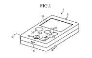
図1および図2に示した分析装置1は、バイオセンサ2を用いて電気化学的手法により試料の分析を行うためのものであり、持ち運びが可能な携帯型として構成されている。この分析装置1は、複数のバイオセンサ2を内部に収容したものであり、筐体3、コネクタ4、センサ供給機構50,51、レーザ発振機構6およびセンサ検知機構7を備えている。 The analysis apparatus 1 shown in FIGS. 1 and 2 is for analyzing a sample by an electrochemical method using a
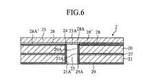
図3ないし図6に示したように、バイオセンサ2は、使い捨てとして構成されたものであり、血液や間質液といった体液における特定成分(たとえばグルコース、コレステロールあるいは乳酸)を分析するために使用されるものである。このバイオセンサ2は、全体として矩形板状に形成されており、その寸法は、たとえば(2〜10mm)×(2〜10mm)×(0.5〜2mm)とされている。バイオセンサ2は、作用極20および対極21を積層したものであり、キャピラリ23、試薬層24、カバー25および排気流路26をさらに備えている。 As shown in FIGS. 3 to 6, the
作用極20および対極21は、キャピラリ23に導入された体液に電圧を印加するとともに、そのときの応答電流を測定するために利用されるものである。作用極20および対極21は、貫通孔20A,21Aを有するとともに、同一または略同一の形状とされている。貫通孔20A,21Aは、キャピラリ23を規定するものであり、作用極20および対極21の中央部において、直径が0.2〜1mmの円形に形成されている。作用極20および対極21は、導電性を有する磁性材料、たとえばニッケルにより、(2〜10mm)×(2〜10mm)×(0.2〜1mm)に形成されている。 The working
作用極20と対極21との間には、絶縁層27が介在しており、この絶縁層27により作用極20と対極21とが接合されている。絶縁層27は、キャピラリ23を規定する貫通孔27Aが中央部に形成されたものであり、たとえば公知のホットメルトシートにより厚みが20〜100μmに形成されている。貫通孔27Aの直径は、作用極20および対極21の貫通孔20A,21Aと同一または略同一とされる。 An
作用極20および対極21の表面には、絶縁層28,28′,29が形成されている。絶縁層28,29は、体液が作用極20および対極21の表面20B,21Bに付着するのを抑制するためのものである。これらの絶縁層28,29もまた、絶縁層27と同様に、公知のホットメルトシートにより形成されている。絶縁層28,29にはキャピラリ23を規定する貫通孔28A,29Aが形成されている。貫通孔28A,29Aの直径は、作用極20および対極21の貫通孔20A,21Aと同一または略同一とされる。絶縁層28′には排気流路26を規定するスリット28A′が形成されている。絶縁層28,28′,29にはさらに、作用極20または対極21の表面20B,21Bを露出させるための孔部28B,28B′29Bが形成されている。これらの孔部28B,28B′,29Bにより、後述するコネクタ4の測定用端子42,43が作用極20または対極21に接触可能とされている。
キャピラリ23は、開口23Aから導入された体液を、毛細管現象を利用して開口23Bに向けて移動させて保持するためのものであるとともに、後述するレーザ発振機構6からのレーザ光の進行を許容するためのものである。キャピラリ23は、作用極20、対極21および絶縁層27〜29の貫通孔20A,21A,27A〜29Aにより規定されており、その容積は、たとえば0.03〜10μLに設定されている。 The capillary 23 is used to move and hold the body fluid introduced from the
試薬層24は、体液中の特定成分の分析に必要な試薬を含んだものであり、キャピラリ23の内面を覆うように形成されている。この試薬層24は、たとえば電子伝達物質および酸化還元酵素を含んでいるとともに、体液に対して容易に溶解する固体状に形成されている。したがって、キャピラリ23に体液を導入した場合には、試薬層24が溶解し、キャピラリ23の内部には、電子伝達物質、酸化還元酵素および体液を含む液相反応系が構築される。 The
酸化還元酵素としては、分析すべき特定成分の種類により選択され、たとえばグルコースの分析を行なう場合には、グルコースデヒドロゲナーゼ(GDH)やグルコースオキシダーゼ(GOD)を用いることができる。電子伝達物質としては、たとえばルテニウム錯体や鉄錯体を使用することができ、典型的には[Ru(NH3)6]Cl3やK3[Fe(CN)6]を使用することができる。The oxidoreductase is selected depending on the type of the specific component to be analyzed. For example, when glucose is analyzed, glucose dehydrogenase (GDH) or glucose oxidase (GOD) can be used. As the electron transfer substance, for example, a ruthenium complex or an iron complex can be used, and typically [Ru (NH3 )6 ] Cl3 or K3 [Fe (CN)6 ] can be used.
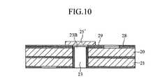
カバー25は、キャピラリ23の開口部23Bを封止するものであり、貫通孔25Aを有している。貫通孔25Aは、絶縁層28,28′の孔部28B,28B′とともに作用極20を露出させるためのものである。カバー25は、レーザ光を透過可能な材料、たとえば透明なガラスやPETにより、作用極20の全体を覆うように形成されている。 The
排気流路26は、絶縁層28′のスリット28A′により規定されている。スリット28A′は、絶縁層28′の縁にまで形成されているとともに、キャピラリ23に繋がるものである。すなわち、排気流路26は、キャピラリ23の気体を排出することができる。 The
図1および図2に示した筐体3は、分析装置1の外観形状を規定するものであり、複数の操作ボタン30、表示パネル31、センサ収容部32および廃棄口33が設けられたものである。複数の操作ボタン30は、分析動作などを行わせるための信号を生成させ、あるいは各種の設定(分析条件の設定や被験者のID入力など)を行うためのものである。表示パネル31は、分析結果やエラーである旨を表示するとともに、設定時における操作手順や操作状況などを表示するためのものである。センサ収容部32は、複数のバイオセンサ2を積層状態で収容するためのものであり、載置部34および開閉可能な蓋35を有している。載置部34は、コイルバネ37により上方(蓋35の方向)に向けて付勢されている。廃棄口33は、分析の終了したバイオセンサ2を分析装置1から廃棄するための部分である。 The housing 3 shown in FIG. 1 and FIG. 2 defines the external shape of the analyzer 1, and is provided with a plurality of
図7に示したように、コネクタ4は、分析対象となるバイオセンサ2を保持するとともに、バイオセンサ2の作用極20と対極21との間に電圧を印加するためのものである。このコネクタ4は、固定体40、可動体41、および測定用端子42,43を備えている。 As shown in FIG. 7, the
固定体40は、測定用端子42を支持したものであり、貫通孔40Aを有している。この貫通孔40Aは、レーザ発振機構6からのレーザ光の進行を許容するためのものである。固定体40には、後述するセンサ検知機構7(弾性体70およびスイッチ71)が配置されている。 The fixed
可動体41は、測定用端子43を支持したものである。この可動体41は、コイルバネ48を介して固定体40に連結されており、上方に向けて付勢されているとともに、上下方向に変位可能とされている。可動体41は、凸部41Aおよび貫通孔41Bを有している。凸部41Aは、体液を採取するときに指先などの皮膚を押し付ける部分であり、筐体3の貫通孔36(図1参照)を介して露出している。すなわち、可動体41は、凸部41Aに指先などの皮膚を押し付けることにより下方に変位するように構成されている。貫通孔41Bは、レーザ発振機構6からのレーザ光の進行を許容するためのものである。この貫通孔41Bは、凸部41Aにまで連続して設けられており、凸部41Aの端面において装置外部と連通している。すなわち、貫通孔41Bの開口部41Baは体液採取口として機能する。 The
測定用端子42,43は、板バネとして構成されている。測定用端子42,43は、バイオセンサ2の作用極20と対極21との間に電圧を印加するためのものである。測定用端子42は、作用極20に接触させるためのものであり、接点42Aが上方に向けて突出している。測定用端子43は、対極21に接触させるためのものであり、接点43Aが下方に向けて突出している。 The
コネクタ4では、固定体40から板バネとして構成された測定用端子42の接点42Aが上方に向けて突出している一方で、可動体41から測定用端子43の接点43Aが下方に向けて突出している。そのため、コネクタ4においては、固定体40と可動体41との間には、バイオセンサ2を保持させることができる。 In the
図8Aないし図8Cに示したように、センサ供給機構50,51は、センサ収容部32に積層された複数のバイオセンサ2のうち、最上層に位置するバイオセンサ2を、コネクタ4に供給するためのものである。このセンサ供給機構50,51は、電磁石50,51を備えている。電磁石50は、センサ収容部32に隣接して設けられたものであり、電磁石51はコネクタ4に隣接して設けられたものである。電磁石50は、バイオセンサ2を磁化させるとともに、磁化させたバイオセンサ2との間に反発力を作用させるためのものである。電磁石51は、磁化させたバイオセンサ2との間に引力を作用させるためのものである。 As shown in FIGS. 8A to 8C, the
図9Aおよび図9Bに示したように、レーザ発振機構6は、皮膚から血液などの体液を出液させるときに、皮膚に照射すべきレーザ光を出射するものである。このレーザ発振機構6は、レーザダイオードなどのレーザ光発振部60および集光レンズ61を備えている。 As shown in FIGS. 9A and 9B, the
図7、図9Aおよび図9Bに示したように、センサ検知機構7は、コネクタ4の目的位置にバイオセンサ2が存在するか否かを検知するためのものであり、弾性体70およびスイッチ71を備えている。弾性体70は、コネクタ4における固定体40に固定されたものであり、スイッチ71と短絡させるためのものである。弾性体70は、可動体41が下方に移動させられたときにスイッチ71をオンするように構成されている。スイッチ71は、分析装置1における所定の動作をオン・オフするためのものであり、スイッチ71がオンのときに、レーザ光発振部60を制御してレーザ光を出射させるように構成されている。 As shown in FIGS. 7, 9A, and 9B, the
なお、弾性体70は、可動体41に固定してもよく、また板バネ状以外の形状あるいは材料の性状により弾性を付与したものであってもよい。 The
次に、分析装置1の動作について説明する。 Next, the operation of the analyzer 1 will be described.
図8Aないし図8Cに示したように、分析装置1では、センサ収容部32に複数のバイオセンサ2がセットされた場合に、あるいは分析が終了した場合には、センサ供給機構50,51によってセンサ収容部32からコネクタ4に対してバイオセンサ2が供給する。 As shown in FIGS. 8A to 8C, in the analyzer 1, when a plurality of
より具体的には、センサ供給機構50,51では、図8Aに示したように、まず電磁石50によりバイオセンサ2を磁化させる。図示した例では、電磁石50はN極がバイオセンサ2と隣接させられており、バイオセンサ2は電磁石50に近い側がS極、遠い側がN極として磁化される。このとき、電磁石51は磁極が発生しない状態とされている。 More specifically, in the
次に、図8Bおよび図8Cに示したように、電磁石50の極性を反転させてバイオセンサ2と電磁石50との間に反発力を発生させる。その一方で、電磁石51に磁極を発生させて電磁石50と逆極性としてバイオセンサ2との間に引力を発生させる。このようにして、電磁石50による反発力と電磁石51による引力によりバイオセンサ2はコネクタ4に向けて移動させられ、コネクタ4にバイオセンサ2が保持される。このとき、コネクタ4における測定用端子42は作用極20に、測定用端子43は対極21にそれぞれ接触する。 Next, as shown in FIGS. 8B and 8C, the repulsive force is generated between the
センサ供給機構50,51は、電磁石50,51を利用したものに限らず、たとえば公知のアクチュエータを利用したものであってもよい。この場合、バイオセンサ2は、必ずしも作用極20および対極21を磁性材料により形成する必要はない。 The
図9Aおよび図9Bに示したように、分析装置1を用いて体液中の特定成分の分析を行う場合には、可動体41の凸部41Aに指先などの皮膚を押し付け、可動体41を下方に移動させる。これにより、センサ検知機構7における弾性体70が可動体41(バイオセンサ2)とともに下方に変位する。弾性体70の下方変位により、弾性体70がスイッチ71をオンさせ、分析装置1の電源がオンされる。このとき、レーザ発振機構6からレーザ光が出射される。 As shown in FIGS. 9A and 9B, when analyzing a specific component in a body fluid using the analyzer 1, skin such as a fingertip is pressed against the
図7に示したように、バイオセンサ2はキャピラリ23を有するものであり、固定体40および可動体41は貫通孔40A,41Bを有するものである。そのため、レーザ発振機構60から出射されたレーザ光は、凸部41Aに載置された皮膚に照射される。皮膚にレーザ光を照射した場合には、皮膚から血液などの体液が出液される。このとき、皮膚が凸部41Aに押し付けられているため、皮膚が鬱血させられ、血液などの体液の出液が促進される。 As shown in FIG. 7, the
また、バイオセンサ2は、カバー25により封止されたキャピラリ23の開口部23Aがレーザ光の入射側となるように分析装置1のコネクタ4に装着されている。すなわち、バイオセンサ2では、皮膚にレーザ光を照射したときに生じる煙あるいは血液や皮膚の飛散によりレーザ発振機構6における集光レンズ61やレーザ光発振部60における光出射面が汚れてしまうことを抑制することができる。そのため、皮膚に対して適切にレーザ光を照射することができる。 The
また、使い捨てのバイオセンサ2によって煙、血液あるいは皮膚などによる汚れの付着が防止されているため、集光レンズ61などの洗浄を行なう必要がなくなる。そのため、使用者の負担が軽減されるとともに、集光レンズ61などの洗浄を行なった場合に生じるレーザ出力の不均一さが生じることを抑制することができる。 Further, since the
皮膚からの体液は、バイオセンサ2のキャピラリ23において生じる毛細管力により、キャピラリ23に導入される。キャピラリ23においては、試薬層24が溶解して液相反応系が構築される。 Body fluid from the skin is introduced into the capillary 23 by the capillary force generated in the
一方、スイッチ71がオンされた場合には、コネクタ4における測定用端子42、43との間に電圧が印加されることにより、作用極20と対極21との間に電圧が印加され、液相反応系に対しても電圧が印加される。これにより、酸化還元酵素によって、たとえば体液中のグルコースなどの特定成分が還元され(電子が取り出され)、その電子が電子伝達物質を介して作用極20に供給される。作用極20に供給された電子の量は、測定用端子42,43を介して応答電流として測定される。分析装置1においては、先の応答電流に基づいて、グルコースなどの特定成分の濃度が演算される。この演算結果は、図1に示した表示パネル31において表示される。 On the other hand, when the
体液の分析が終了した場合には、使用済みのバイオセンサ2が廃棄口33を介して廃棄される。このようなバイオセンサ2の廃棄は、分析装置1に設けられた廃棄機構において自動的に行うようにしてもよく、また使用者によるレバー操作などにより手動で行うようにしてもよい。また、使用済みのバイオセンサ2を廃棄した場合には、センサ供給機構50,51によってコネクタ4に対して新たなバイオセンサ2が供給される。 When the analysis of the body fluid is finished, the used
なお、バイオセンサ2は、必ずしも分析装置1に予め収容しておいたものを使用する必要はなく、分析時に分析装置1におけるコネクタ4に装着するようにしてもよい。 The
図10に示したように、カバー25′は、作用極20の全体を覆うように形成する必要はなく、キャピラリ23における開口部23Bを選択的に封止するものであってもよい。 As shown in FIG. 10, the
本発明は、上述した実施の形態には限定されず、種々に変更可能である。たとえば、本発明は、図11ないし図19に示したように、絶縁性基板上に作用極および対極を設けたバイオセンサに対しても適用可能である。 The present invention is not limited to the embodiments described above, and can be variously modified. For example, the present invention can be applied to a biosensor in which a working electrode and a counter electrode are provided on an insulating substrate as shown in FIGS.
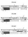
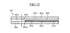
図11ないし図13に示したバイオセンサ8Aは、絶縁性基板80Aに作用極81Aおよび対極82Aを設けたものであり、絶縁性基板80Aに対して、一定間隔離れて配置された一対のスペーサ83Aを介してカバー84Aが接合されている。このバイオセンサ8Aでは、一対のスペーサ83Aの間にキャピラリ85Aが設けられており、このキャピラリ85Aの内部に試薬部86Aが形成されている。 The
絶縁性基板80Aには、貫通孔80Aaが設けられている。この貫通孔80Aaは、一対のスペーサ83Aの隙間とともに、レーザ光の進行を許容する貫通孔87Aが規定されている。貫通孔87Aは、カバー84Aにより塞がれている。カバー84Aは、レーザ光を透過可能なようにガラスやPETにより透明に形成されている。 The insulating
バイオセンサ8Aにおいても、レーザ光を進行させる貫通孔87Aがカバー84Aにより塞がれているため、レーザ発振機構6における集光レンズ61(図7参照)などが汚れてしまうことを抑制することができる。 Also in the
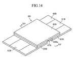
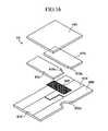
図14ないし図16に示したバイオセンサ8Bは、絶縁性基板80Bに作用極81Bおよび対極82Bを設けたものであり、絶縁性基板80Bに対して、一定間隔離れて配置された一対のスペーサ83Bを介して、カバー84Bが接合されている。このバイオセンサ8Bでは、一対のスペーサ83Bの間にキャピラリ85Bが設けられており、このキャピラリ85Bの内部に試薬部86Bが形成されている。 The
絶縁性基板80Bには、切欠80Baが設けられている。この切欠80Baは、一対のスペーサ83Bの切欠83Baとともに、レーザ光の進行を許容する切欠87Bを規定するものである。切欠87Bは、カバー84Bにより塞がれている。カバー84Bは、レーザ光を透過可能なようにガラスやPETにより透明に形成されている。 The insulating
バイオセンサ8Bにおいても、レーザ光を進行させる切欠87Bがカバー84Bにより塞がれているため、レーザ発振機構6における集光レンズ61(図7参照)などが汚れてしまうことを抑制することができる。 Also in the
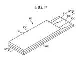
図17ないし図19に示したバイオセンサ8Cは、絶縁性基板80Cに作用極81Cおよび対極82Cを設けたものであり、絶縁性基板80Cに対して、スリット83Cが設けられたスペーサ84Cを介して、カバー85Cが接合されている。このバイオセンサ8Cでは、スリット83Cによりキャピラリ86Cが設けられており、このキャピラリ86Cの内部に試薬部87Cが形成されている。 The
絶縁性基板80Cには、貫通孔80Caが設けられている。この貫通孔80Caは、スリット83Cとともに、レーザ光の進行を許容する貫通孔88Cを規定するものである。貫通孔86Cは、カバー85Cにより塞がれている。カバー85Cは、レーザ光を透過可能なようにガラスやPETにより透明に形成されている。 A through hole 80Ca is provided in the insulating
絶縁性基板80Cにはさらに、貫通孔80Cbが設けられている、この貫通孔80Cbは、キャピラリ86Cの気体を排出するためのものである。 The insulating
バイオセンサ8Cにおいても、レーザ光を進行させる貫通孔88Cがカバー85Cにより塞がれているため、レーザ発振機構6における集光レンズ61(図7参照)などが汚れてしまうことを抑制することができる。 Also in the
本発明はさらに、作用極および対極を備えたバイオセンサに限らず、比色により体液の分析を行なうように構成されたバイオセンサなどの分析用具に対しても適用することができる。 The present invention can be applied not only to a biosensor having a working electrode and a counter electrode, but also to an analysis tool such as a biosensor configured to analyze a body fluid by colorimetry.
Claims (4)
Translated fromJapanese上記孔部における上記レーザ光が入射する開口部を塞ぐとともに、上記レーザ光を透過可能なカバーと、
互いに電気的に絶縁した状態で積層されているとともに、上記孔部を規定する貫通孔を有する複数の電極と、
上記電極と上記カバーとの間に介在する絶縁層に対して、上記孔部に連通するスリットを形成することにより設けられ、上記孔部の気体を外部に排出するための排気流路と、
を備えた、分析用具。A hole through which laser light applied to the skin travels to discharge body fluid;
A cover that closes the opening of the hole where the laser beam is incident and that can transmit the laser beam;
A plurality of electrodes that are stacked in a state of being electrically insulated from each other, and that have a through hole that defines the hole,
For the insulating layer interposed between the electrode and the cover, provided by forming a slit that communicates with the hole, an exhaust passage for discharging the gas in the hole to the outside,
An analytical tool with
上記流路に形成された試薬部と、
をさらに備えている、請求項1又は請求項2に記載の分析用具。A flow path for moving the body fluid sucked in the hole,
A reagent part formed in the flow path;
The analysis tool according toclaim 1 or 2 , further comprising:
Priority Applications (1)
| Application Number | Priority Date | Filing Date | Title |
|---|---|---|---|
| JP2009513017AJP4880753B2 (en) | 2007-04-29 | 2008-04-29 | Analysis tool |
Applications Claiming Priority (4)
| Application Number | Priority Date | Filing Date | Title |
|---|---|---|---|
| JP2007120396 | 2007-04-29 | ||
| JP2007120396 | 2007-04-29 | ||
| JP2009513017AJP4880753B2 (en) | 2007-04-29 | 2008-04-29 | Analysis tool |
| PCT/JP2008/058222WO2008136473A1 (en) | 2007-04-29 | 2008-04-29 | Analysis instrument |
Publications (2)
| Publication Number | Publication Date |
|---|---|
| JPWO2008136473A1 JPWO2008136473A1 (en) | 2010-07-29 |
| JP4880753B2true JP4880753B2 (en) | 2012-02-22 |
Family
ID=39943580
Family Applications (1)
| Application Number | Title | Priority Date | Filing Date |
|---|---|---|---|
| JP2009513017AExpired - Fee RelatedJP4880753B2 (en) | 2007-04-29 | 2008-04-29 | Analysis tool |
Country Status (6)
| Country | Link |
|---|---|
| US (1) | US20100292608A1 (en) |
| EP (1) | EP2153775A1 (en) |
| JP (1) | JP4880753B2 (en) |
| KR (1) | KR20100031568A (en) |
| TW (1) | TW200911204A (en) |
| WO (1) | WO2008136473A1 (en) |
Families Citing this family (2)
| Publication number | Priority date | Publication date | Assignee | Title |
|---|---|---|---|---|
| WO2009031313A1 (en) | 2007-09-04 | 2009-03-12 | Panasonic Corporation | Blood analysis device and blood analysis system using the same |
| WO2016152225A1 (en)* | 2015-03-24 | 2016-09-29 | テルモ株式会社 | Bodily fluid measurement chip and component measurement device set |
Citations (6)
| Publication number | Priority date | Publication date | Assignee | Title |
|---|---|---|---|---|
| JPH0629874B2 (en)* | 1985-06-28 | 1994-04-20 | マイルス ラボラトリ−ズ インコ−ポレ−テッド | Electrode for electrochemical sensor |
| US5554153A (en)* | 1994-08-29 | 1996-09-10 | Cell Robotics, Inc. | Laser skin perforator |
| WO1998047435A1 (en)* | 1997-04-22 | 1998-10-29 | Cell Robotics Inc. | Device for use with a laser perforator apparatus |
| WO2003025559A1 (en)* | 2001-09-11 | 2003-03-27 | Arkray, Inc. | Measuring instrument, installation body, and density measurer |
| JP2003265444A (en)* | 2002-03-15 | 2003-09-24 | Shimadzu Corp | Biological measurement device |
| WO2006093206A1 (en)* | 2005-03-02 | 2006-09-08 | National Institute Of Advanced Industrial Science And Technology | Biosensor coupled with needle |
Family Cites Families (9)
| Publication number | Priority date | Publication date | Assignee | Title |
|---|---|---|---|---|
| US5030310A (en)* | 1985-06-28 | 1991-07-09 | Miles Inc. | Electrode for electrochemical sensors |
| JPH0810208B2 (en) | 1990-07-20 | 1996-01-31 | 松下電器産業株式会社 | Biosensor and biosensor measuring device |
| JPH07102209B2 (en) | 1991-04-12 | 1995-11-08 | 株式会社ヒューテック | Laser device for blood collection |
| JPH0739542A (en)* | 1993-07-30 | 1995-02-10 | Shibuya Kogyo Co Ltd | Device for collecting blood |
| US6233269B1 (en)* | 1998-12-16 | 2001-05-15 | Cell Robotics, Inc. | Apparatus and method for protecting components of a light source |
| US9101302B2 (en)* | 2004-05-03 | 2015-08-11 | Abbott Diabetes Care Inc. | Analyte test device |
| JPWO2006057225A1 (en)* | 2004-11-25 | 2008-06-05 | 松下電器産業株式会社 | Sensor device |
| JP4952078B2 (en)* | 2006-06-15 | 2012-06-13 | パナソニック株式会社 | Blood test equipment |
| JP4844251B2 (en)* | 2006-06-15 | 2011-12-28 | パナソニック株式会社 | Blood test equipment |
- 2008
- 2008-04-29EPEP08752232Apatent/EP2153775A1/ennot_activeWithdrawn
- 2008-04-29JPJP2009513017Apatent/JP4880753B2/ennot_activeExpired - Fee Related
- 2008-04-29TWTW097115756Apatent/TW200911204A/enunknown
- 2008-04-29USUS12/451,175patent/US20100292608A1/ennot_activeAbandoned
- 2008-04-29WOPCT/JP2008/058222patent/WO2008136473A1/enactiveApplication Filing
- 2008-04-29KRKR1020097024686Apatent/KR20100031568A/ennot_activeWithdrawn
Patent Citations (6)
| Publication number | Priority date | Publication date | Assignee | Title |
|---|---|---|---|---|
| JPH0629874B2 (en)* | 1985-06-28 | 1994-04-20 | マイルス ラボラトリ−ズ インコ−ポレ−テッド | Electrode for electrochemical sensor |
| US5554153A (en)* | 1994-08-29 | 1996-09-10 | Cell Robotics, Inc. | Laser skin perforator |
| WO1998047435A1 (en)* | 1997-04-22 | 1998-10-29 | Cell Robotics Inc. | Device for use with a laser perforator apparatus |
| WO2003025559A1 (en)* | 2001-09-11 | 2003-03-27 | Arkray, Inc. | Measuring instrument, installation body, and density measurer |
| JP2003265444A (en)* | 2002-03-15 | 2003-09-24 | Shimadzu Corp | Biological measurement device |
| WO2006093206A1 (en)* | 2005-03-02 | 2006-09-08 | National Institute Of Advanced Industrial Science And Technology | Biosensor coupled with needle |
Also Published As
| Publication number | Publication date |
|---|---|
| KR20100031568A (en) | 2010-03-23 |
| WO2008136473A1 (en) | 2008-11-13 |
| TW200911204A (en) | 2009-03-16 |
| JPWO2008136473A1 (en) | 2010-07-29 |
| EP2153775A1 (en) | 2010-02-17 |
| US20100292608A1 (en) | 2010-11-18 |
Similar Documents
| Publication | Publication Date | Title |
|---|---|---|
| EP1997431A1 (en) | Biosensor and apparatus for measuring concentration of components | |
| JPWO2002048703A1 (en) | Analytical element, measuring instrument and substrate quantification method using the same | |
| JP5002266B2 (en) | Body fluid collection device | |
| JPWO2007063948A1 (en) | Sensor-lancet integrated device and body fluid collecting method using the same | |
| JP2009525794A (en) | Personal portable blood glucose meter with replaceable specimen cartridge | |
| US8128981B2 (en) | Biosensor manufacturing method | |
| JP4443718B2 (en) | Biological sample measuring device | |
| JPWO2008136472A1 (en) | Analysis system | |
| JPWO2004113927A1 (en) | Analytical tool with liquid reservoir | |
| JP2015508900A (en) | Coplanar analysis test strip with stacked unidirectional contact pads | |
| CN105556298A (en) | Anomalous signal error trap for an analyte measurement | |
| JP5216930B2 (en) | Sensor chip, measuring instrument using the same, and blood test apparatus | |
| US20140326599A1 (en) | Electrochemical test sensor with light guide | |
| JP4352152B2 (en) | Analysis tool | |
| JP5357876B2 (en) | Test sensor and instrument contacts attached to the side | |
| JP4880753B2 (en) | Analysis tool | |
| JP5212990B2 (en) | Analysis equipment | |
| JP2006284481A (en) | Biosensor detector | |
| JP5303475B2 (en) | Blood sensor and blood test apparatus | |
| US8357106B2 (en) | Analysis device | |
| JP2005261960A (en) | Blood analyzer | |
| JP2014102144A (en) | Glycosylated hemoglobin measuring kit and glycosylated hemoglobin measuring method | |
| CN201075107Y (en) | biochemical sensor | |
| JP6668477B2 (en) | Measuring pipette tip, measuring device and measuring method using the measuring pipette tip |
Legal Events
| Date | Code | Title | Description |
|---|---|---|---|
| RD01 | Notification of change of attorney | Free format text:JAPANESE INTERMEDIATE CODE: A7421 Effective date:20100520 | |
| A621 | Written request for application examination | Free format text:JAPANESE INTERMEDIATE CODE: A621 Effective date:20110204 | |
| A131 | Notification of reasons for refusal | Free format text:JAPANESE INTERMEDIATE CODE: A131 Effective date:20110830 | |
| A521 | Request for written amendment filed | Free format text:JAPANESE INTERMEDIATE CODE: A523 Effective date:20110922 | |
| TRDD | Decision of grant or rejection written | ||
| A01 | Written decision to grant a patent or to grant a registration (utility model) | Free format text:JAPANESE INTERMEDIATE CODE: A01 Effective date:20111108 | |
| A01 | Written decision to grant a patent or to grant a registration (utility model) | Free format text:JAPANESE INTERMEDIATE CODE: A01 | |
| A61 | First payment of annual fees (during grant procedure) | Free format text:JAPANESE INTERMEDIATE CODE: A61 Effective date:20111201 | |
| R150 | Certificate of patent or registration of utility model | Free format text:JAPANESE INTERMEDIATE CODE: R150 | |
| FPAY | Renewal fee payment (event date is renewal date of database) | Free format text:PAYMENT UNTIL: 20141209 Year of fee payment:3 | |
| LAPS | Cancellation because of no payment of annual fees |