JP4876019B2 - Defect inspection apparatus and method - Google Patents
Defect inspection apparatus and methodDownload PDFInfo
- Publication number
- JP4876019B2 JP4876019B2JP2007115005AJP2007115005AJP4876019B2JP 4876019 B2JP4876019 B2JP 4876019B2JP 2007115005 AJP2007115005 AJP 2007115005AJP 2007115005 AJP2007115005 AJP 2007115005AJP 4876019 B2JP4876019 B2JP 4876019B2
- Authority
- JP
- Japan
- Prior art keywords
- illumination
- defect
- light
- defect inspection
- inspection method
- Prior art date
- Legal status (The legal status is an assumption and is not a legal conclusion. Google has not performed a legal analysis and makes no representation as to the accuracy of the status listed.)
- Expired - Fee Related
Links
Images


Classifications
- G—PHYSICS
- G01—MEASURING; TESTING
- G01N—INVESTIGATING OR ANALYSING MATERIALS BY DETERMINING THEIR CHEMICAL OR PHYSICAL PROPERTIES
- G01N21/00—Investigating or analysing materials by the use of optical means, i.e. using sub-millimetre waves, infrared, visible or ultraviolet light
- G01N21/84—Systems specially adapted for particular applications
- G01N21/88—Investigating the presence of flaws or contamination
- G01N21/95—Investigating the presence of flaws or contamination characterised by the material or shape of the object to be examined
- G01N21/9501—Semiconductor wafers
- G—PHYSICS
- G01—MEASURING; TESTING
- G01N—INVESTIGATING OR ANALYSING MATERIALS BY DETERMINING THEIR CHEMICAL OR PHYSICAL PROPERTIES
- G01N21/00—Investigating or analysing materials by the use of optical means, i.e. using sub-millimetre waves, infrared, visible or ultraviolet light
- G01N21/84—Systems specially adapted for particular applications
- G01N21/88—Investigating the presence of flaws or contamination
- G01N21/95—Investigating the presence of flaws or contamination characterised by the material or shape of the object to be examined
- G01N21/956—Inspecting patterns on the surface of objects
- G01N21/95623—Inspecting patterns on the surface of objects using a spatial filtering method
- G—PHYSICS
- G01—MEASURING; TESTING
- G01N—INVESTIGATING OR ANALYSING MATERIALS BY DETERMINING THEIR CHEMICAL OR PHYSICAL PROPERTIES
- G01N21/00—Investigating or analysing materials by the use of optical means, i.e. using sub-millimetre waves, infrared, visible or ultraviolet light
- G01N21/84—Systems specially adapted for particular applications
- G01N21/88—Investigating the presence of flaws or contamination
- G01N21/8851—Scan or image signal processing specially adapted therefor, e.g. for scan signal adjustment, for detecting different kinds of defects, for compensating for structures, markings, edges
- G01N2021/8896—Circuits specially adapted for system specific signal conditioning
- G—PHYSICS
- G01—MEASURING; TESTING
- G01N—INVESTIGATING OR ANALYSING MATERIALS BY DETERMINING THEIR CHEMICAL OR PHYSICAL PROPERTIES
- G01N21/00—Investigating or analysing materials by the use of optical means, i.e. using sub-millimetre waves, infrared, visible or ultraviolet light
- G01N21/84—Systems specially adapted for particular applications
- G01N21/88—Investigating the presence of flaws or contamination
- G01N21/95—Investigating the presence of flaws or contamination characterised by the material or shape of the object to be examined
- G01N21/956—Inspecting patterns on the surface of objects
- G01N21/95607—Inspecting patterns on the surface of objects using a comparative method
Landscapes
- Physics & Mathematics (AREA)
- Health & Medical Sciences (AREA)
- Life Sciences & Earth Sciences (AREA)
- Chemical & Material Sciences (AREA)
- Analytical Chemistry (AREA)
- Biochemistry (AREA)
- General Health & Medical Sciences (AREA)
- General Physics & Mathematics (AREA)
- Immunology (AREA)
- Pathology (AREA)
- Investigating Materials By The Use Of Optical Means Adapted For Particular Applications (AREA)
- Testing Or Measuring Of Semiconductors Or The Like (AREA)
Description
Translated fromJapanese本発明は、半導体製造工程、液晶表示素子製造工程プリント基板製造工程等、基板上にパターンを形成して対象物を製作していく製造工程で発生する異物等の欠陥を検出し、分析して対策を施す製造工程における異物等の欠陥の発生状況を検査する欠陥検査装置およびその方法に関する。 The present invention detects and analyzes defects such as foreign matter generated in a manufacturing process of forming an object by forming a pattern on a substrate, such as a semiconductor manufacturing process, a liquid crystal display element manufacturing process, a printed circuit board manufacturing process, etc. The present invention relates to a defect inspection apparatus and method for inspecting the occurrence of defects such as foreign matters in a manufacturing process for which countermeasures are taken.
従来の半導体製造工程では、半導体基板(被検査対象基板)上に異物が存在すると配線の絶縁不良や短絡などの不良原因になり、さらに半導体素子が、微細化して半導体基板中に微細な異物が存在した場合にこの異物が、キャパシタの絶縁不良やゲート酸化膜などの破壊の原因にもなる。これらの異物は、搬送装置の可動部から発生するものや、人体から発生するもの、プロセスガスによる処理装置内で反応生成されたもの、薬品や材料に混入していたものなど種々の原因により種々の状態で混入される。 In a conventional semiconductor manufacturing process, if foreign matter exists on a semiconductor substrate (substrate to be inspected), it may cause a failure such as a wiring insulation failure or a short circuit. Further, the semiconductor element is miniaturized and fine foreign matter is generated in the semiconductor substrate. If present, this foreign substance also causes a failure of insulation of the capacitor and a breakdown of the gate oxide film. These foreign substances are various due to various causes such as those generated from the moving part of the transfer device, those generated from the human body, those generated by reaction in the processing apparatus by the process gas, those mixed in chemicals and materials, etc. It is mixed in the state of.
同様の液晶表示素子製造工程でも、パターン上に異物が混入するなど、何らかの欠陥が生じると、表示素子として使えないものになってしまう。プリント基板の製造工程でも状況は同じであって、異物の混入はパターンの短絡、不良接続の原因になる。 Even in the same liquid crystal display element manufacturing process, if any defect occurs such as foreign matter mixed in the pattern, it cannot be used as a display element. The situation is the same in the manufacturing process of the printed circuit board, and mixing of foreign matters causes short-circuiting of the pattern and defective connection.
従来のこの種の半導体基板上の異物を検出する技術の1つとして、特開昭62−89336号公報(特許文献1)に記載されているように、半導体基板上にレーザを照射して半導体基板上に異物が付着している場合に発生する異物からの散乱光を検出し、直前に検査した同一品種半導体基板の検査結果と比較することにより、パターンによる虚報を無くし、高感度かつ高信頼度な異物及び欠陥検査を可能にするものがある。また、特開昭63−135848号公報(特許文献2)に開示されているように、半導体基板上にレーザを照射して半導体基板上に異物が付着している場合に発生する異物からの散乱光を検出し、この検出した異物をレーザフォトルミネッセンスあるいは2次X線分析(XMR)などの分析技術で分析するものがある。 As one of the conventional techniques for detecting foreign matter on this type of semiconductor substrate, as described in Japanese Patent Application Laid-Open No. 62-89336 (Patent Document 1), a semiconductor is irradiated with a laser to irradiate a semiconductor. By detecting scattered light from foreign matter generated when foreign matter is attached to the substrate and comparing it with the inspection result of the same type semiconductor substrate inspected immediately before, there is no false information due to the pattern, and high sensitivity and high reliability There are those that allow frequent foreign object and defect inspection. Further, as disclosed in Japanese Patent Application Laid-Open No. 63-135848 (Patent Document 2), the scattering from the foreign matter generated when the semiconductor substrate is irradiated with a laser and the foreign matter adheres to the semiconductor substrate. There is one that detects light and analyzes the detected foreign matter by an analysis technique such as laser photoluminescence or secondary X-ray analysis (XMR).
また、上記異物を検査する技術として、被検査対象基板にコヒーレント光を照射して被検査対象基板上の繰り返しパターンから射出する光を空間フィルタで除去し繰り返し性を持たない異物や欠陥を強調して検出する方法が知られている。 In addition, as a technique for inspecting the above foreign matter, the substrate to be inspected is irradiated with coherent light, and the light emitted from the repetitive pattern on the substrate to be inspected is removed by a spatial filter to emphasize foreign matters and defects having no repeatability. There are known methods for detecting them.
また、被検査対象基板上に形成された回路パターンに対して該回路パターンの主要な直線群に対して45度傾けた方向から照射して主要な直線群からの0次回折光を対物レンズの開口内に入力させないようにした異物検査装置が、特開平1−117024号公報(特許文献3)において知られている。この従来技術3においては、主要な直線群ではない他の直線群を空間フィルタで遮光することについても記載されている。 Further, the circuit pattern formed on the substrate to be inspected is irradiated from a direction inclined by 45 degrees with respect to the main line group of the circuit pattern, and the 0th-order diffracted light from the main line group is opened in the objective lens. A foreign substance inspection apparatus which is not allowed to be input to the inside is disclosed in Japanese Patent Laid-Open No. 1-117024 (Patent Document 3). This
また、異物等の欠陥検査装置およびその方法に関する従来技術としては、特開平1−250847号公報(特許文献4)、特開平6−258239号公報(特許文献5)、特開平6−324003号公報(特許文献6)、特開平8−210989号公報(特許文献7)、および特開平8−271437号公報(特許文献8)が知られている。 Further, as prior art relating to a defect inspection apparatus and method for foreign matter, etc., Japanese Patent Laid-Open No. 1-250847 (Patent Document 4), Japanese Patent Laid-Open No. 6-258239 (Patent Document 5), and Japanese Patent Laid-Open No. 6-324003. (Patent Document 6), JP-A-8-210989 (Patent Document 7), and JP-A-8-271437 (Patent Document 8) are known.
また、明視野照明と暗視野照明を同時に行い、各々の検出結果におけるダイ間輝度差を用いて欠陥を検出する欠陥検査装置およびその方法が、米国特許5822055号公報(特許文献9)において知られている。 In addition, a defect inspection apparatus and method for detecting defects by performing bright-field illumination and dark-field illumination at the same time and using a luminance difference between dies in the respective detection results are known from US Pat. No. 5,820,055 (Patent Document 9). ing.
しかしながら、上記特許文献1〜8の従来技術では、不規則な回路パターン部分では、パターンからの散乱光によって欠陥信号が見落とされ、感度が低下する課題があった。 However, in the prior arts of Patent Documents 1 to 8, there is a problem that in an irregular circuit pattern portion, a defect signal is overlooked by scattered light from the pattern, and sensitivity is lowered.
また、上記特許文献9は、明視野画像を用いることで高精度な位置合せを実現しているが、明視野画像においてて欠陥部のコントラストを得るためには、拡大倍率を高めて欠陥寸法と同等あるいは数倍以下の小さな画素寸法にて像を得る必要がある。このため単位時間当たりの検査面積が小さく、スループットが低下する課題があった。また、明視野照明と暗視野照明で同一箇所を同時に照明するため、それにより発生する散乱光分布は一通りであり、明視野照明により発生する散乱光分布と暗視野照明により発生する散乱光分布それぞれの特徴を個別に検出することができない、という課題があった。また、各々の検出結果におけるダイ間輝度差のみを用いるため、それ以外の光学的特徴(偏光、位相等)あるいは画像上の特徴(コントラスト等)を検出することができないという課題があった。 Moreover, although the said patent document 9 implement | achieves highly accurate alignment by using a bright-field image, in order to obtain the contrast of a defect part in a bright-field image, it raises a magnification and raises a defect dimension. It is necessary to obtain an image with a small pixel size equivalent or several times smaller. Therefore, there is a problem that the inspection area per unit time is small and the throughput is lowered. Also, since the same spot is illuminated simultaneously with bright field illumination and dark field illumination, the scattered light distribution generated by this is one way. The scattered light distribution generated by bright field illumination and the scattered light distribution generated by dark field illumination. There was a problem that each feature could not be detected individually. Further, since only the luminance difference between the dies in each detection result is used, there is a problem that other optical characteristics (polarization, phase, etc.) or image characteristics (contrast, etc.) cannot be detected.
本発明の目的は、上記課題を解決すべく、欠陥と同等の強度の散乱光を発するパターンを有する被検査対象基板上の欠陥を、高速で、しかも高精度に検査できるようにした欠陥検査装置およびその方法を提供することにある。 SUMMARY OF THE INVENTION An object of the present invention is to provide a defect inspection apparatus capable of inspecting a defect on a substrate to be inspected having a pattern that emits scattered light having the same intensity as that of a defect at high speed and with high accuracy in order to solve the above-described problems. And providing a method thereof.
上記目的を達成するために、本発明は、光源から出射した光を検査対象基板上の所定の領域に所定の複数の光学条件をもって導く照明工程と、前記所定領域において、前記複数の光学条件に対応して生じる複数の散乱光分布の各々につき、所定の方位角範囲および所定の仰角範囲に伝播する散乱光成分を受光器に導き電気信号を得る検出工程と、該検出工程において得られる複数の電気信号に基づいて欠陥を判定する欠陥判定工程とを有することを特徴とする。 In order to achieve the above object, the present invention provides an illumination process for guiding light emitted from a light source to a predetermined area on a substrate to be inspected with a plurality of predetermined optical conditions, and the predetermined area satisfies the plurality of optical conditions. For each of a plurality of scattered light distributions generated correspondingly, a detection step for obtaining an electrical signal by guiding a scattered light component propagating to a predetermined azimuth angle range and a predetermined elevation angle range to a light receiver, and a plurality of obtained in the detection step A defect determination step of determining a defect based on the electrical signal.
また、光源から出射した光を検査対象基板上の所定の領域に所定の複数の光学条件をもって導く照明工程と、前記所定領域において、前記複数の光学条件に対応して生じる複数の散乱光分布の各々につき、所定の複数の光学条件範囲に含まれる散乱光成分を受光器に導き複数の電気信号を得る検出工程と、該検出工程において得られる複数の電気信号に基づいて欠陥を判定する欠陥判定工程とを有することを特徴とする。 An illumination process for guiding light emitted from a light source to a predetermined area on a substrate to be inspected with a predetermined plurality of optical conditions, and a plurality of scattered light distributions corresponding to the plurality of optical conditions in the predetermined area For each, a detection process for obtaining a plurality of electrical signals by guiding scattered light components included in a predetermined plurality of optical condition ranges to a light receiver, and a defect determination for determining a defect based on the plurality of electrical signals obtained in the detection process And a process.
光源から出射した光を検査対象基板上の所定の領域に所定の光学条件をもって導く照明工程と、前記所定領域において生じる散乱光分布を、所定の複数の光学条件範囲に含まれる散乱光成分を受光器に導き複数の電気信号を得る検出工程と、該検出工程において得られる複数の電気信号に基づいて欠陥を判定する欠陥判定工程とを有することを特徴とする。 An illumination process for guiding light emitted from a light source to a predetermined region on a substrate to be inspected with a predetermined optical condition, and scattered light distribution generated in the predetermined region, and receiving scattered light components included in a predetermined plurality of optical condition ranges And a defect determination step of determining a defect based on the plurality of electrical signals obtained in the detection step.
前記検出工程において、前記照明工程にて発生した光成分のうち正反射光成分を除いた光成分のみを検出することを特徴とする。 In the detection step, only the light component excluding the specular reflection light component from the light component generated in the illumination step is detected.
本発明によれば、散乱光を発するパターンが存在する検査対象基板に対して、微小な欠陥を高速で、しかも高精度に検査することができる。 ADVANTAGE OF THE INVENTION According to this invention, a micro defect can be test | inspected at high speed and with high precision with respect to the test object board | substrate with the pattern which emits scattered light.
本発明の実施の形態を図1から図20を用いて説明する。以下では、半導体ウェハ上の欠陥検査を例にとって説明する。 Embodiments of the present invention will be described with reference to FIGS. Hereinafter, a defect inspection on a semiconductor wafer will be described as an example.
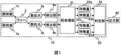
本発明の構成を図1に示す。光学部10は、複数の照明部1a、1b、および複数の検出部4a、4bからなる。照明部1aと照明部1bは互いに異なる照明光を検査対象基板2に照射する。照明部1aおよび照明光1b各々による照明光にて、散乱光3aおよび3bが発生し、各々検出部4aおよび4bにより散乱光強度信号として検出される。検出した散乱光強度信号は処理部20に入力される。処理部20は前処理部21、判定部23からなる。光学部10にて検出された複数の散乱光強度信号が前処理部21に入力される。前処理部21では各々の入力信号に対し、信号補正、位置合せ、特徴量抽出など後述する前処理を行い、入力信号に1つあるいは複数の特徴量22a、22b、22c、22dを出力する。判定部23において、前処理部21より入力された複数の特徴量22a、22b、22c、22dを用いて後述する欠陥判定処理を行い、欠陥情報を出力する。出力部40は、処理部20より得られた欠陥情報を、ユーザに分かる形で出力する。 The configuration of the present invention is shown in FIG. The
散乱光3aおよび3bは、各々照明部1aおよび1bに対応して発生する散乱光分布を指す。照明部1aによる照明光の光学条件と照明部1bによる照明光の光学条件が異なれば、各々によって発生する散乱光3aと散乱光3bは互いに異なる。本明細書において、ある照明光によって発生した散乱光の光学的性質およびその特徴を、その散乱光の散乱光分布と呼ぶ。散乱光分布とは、より具体的には、散乱光の出射位置・出射方位・出射角度に対する、強度・振幅・位相・偏光・波長・コヒーレンシなどの光学パラメータ値の分布を指す。
図1の構成を実現する具体的な装置構成を図2に示す。図2に示す装置は、照明部101a、101b、対物レンズ102、光路分岐素子103、フィルタ部104a、104b、結像レンズ105a、105b、検出部106a、106b、処理部20、全体制御部301、表示部302、演算部303、記憶部304、ステージ駆動部151、X-Y-Z-θステージ152から構成されている。照明部101a、101b、対物レンズ102、光路分岐素子103、フィルタ部104a、104b、結像レンズ105a、105b、検出部106a、106b、ステージ駆動部151、X-Y-Z-θステージ152が光学部10を構成する。また、検査対象基板2上の任意の位置の静止画像(光学顕微像あるいは電子顕微像)を得ることが可能なレビュー顕微鏡(図示せず)を備える。 A specific apparatus configuration for realizing the configuration of FIG. 1 is shown in FIG. 2 includes an
動作の概略を説明する。照明部101a、101bにより検査対象基板2に対して照明光が照射される。検査対象基板2から発した散乱光は対物レンズ3で集光された後、光路分岐素子103により光路が分岐され、一方は空間フィルタ104a、結像レンズ105aを介して、検出部106aにて電気信号に変換される。一方は空間フィルタ104b、結像レンズ105bを介して、検出部106bにて電気信号に変換される。得られた複数の電気信号に基づき、処理部20において欠陥が判定される。判定された結果は全体制御部301を介し、記憶部304に記憶され、表示部302に表示される。 An outline of the operation will be described. Illumination light is irradiated to the
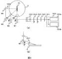
照明部の構成を図3(a)に示す。ここでは互いに異なる複数の波長の照明を行う例を示す。照明光源1010は、互いに異なる複数の波長の光を発する光源1010a、1010bから成り、光軸をほぼ同じくした互いに異なる複数の波長の光を射出する。照明光源1010としては単一光源で複数の波長の光を発するものを用いれば光軸を一致させる調整が不要である。照明光源1010に用いる光源としては、検査対象基板2を高照度で照明するためには、レーザ光源が適している。微小な欠陥の散乱効率を上げるためには、短波長の、深紫外光レーザ(Deep Ultraviolet光)・真空紫外光レーザ・YAGレーザ第3あるいは第4高調波・水銀ランプ・キセノンランプなどの光源が適している。また、光学部を構成する部品コストおよびメンテナンスコストを抑えるにはYAGレーザ第2高調波・ハロゲンランプ・水銀ランプ・キセノンランプなどの可視光波長の光源が適している。 The structure of the illumination unit is shown in FIG. Here, an example in which illumination with a plurality of different wavelengths is performed is shown. The
光源1010より発した照明光は、アッテネータ1011により強度が制御される。偏光板1012が必要に応じて設置され、光源より発する照明光の偏光が直線偏光に揃えられる。位相板1013、1014により、照明光の偏光状態が任意に設定される。位相板1013、1014は、光軸の周りに回転可能なλ/2板あるいはλ/4板あるいは特定方位の振動成分の位相量を制御可能な光学素子で構成される。ビームエキスパンダ1015によって、照明光のビーム径が拡大される。照明光はミラー群M1〜M7によりビーム成型素子1017を介して検査対象基板2上の照野F1に導かれる。以下、光路1016をとった場合を例にとって説明する。ミラーM1およびM2を光路より退避することで、照明光はミラーM3、ミラーM4により反射され、光路1016をとる。図3(b)は、ミラーM4反射後の、検査対象基板2までの構成を示す側面図である。ビーム成型光学素子1017としてシリンドリカルレンズを、光路中の適切に配置することで、照明光が検査対象基板2上で細長い楕円状の照野領域F1に集光される。線状あるいは広面積の矩形状・円形状の照野を形成することで、単位時間当たりの検査面積を増やし、高速検査を実現する。あるいはビーム成型光学素子1017としてレンズを用いて点状のスポットに集光し、スポットを走査することで、高解像度の検査が行われる。あるいはビーム成型光学素子1017として回折光学素子(DOE)、ホモジナイザなどを用いることで、検査対象基板2上に回折限界の範囲内で任意の形状、任意の照度分布の照野F1が形成される。また、ミラー群M1〜M7の配置および挿入、退避機構により、検査対象基板2に対する照明の入射角および方位角を、光学部の他の部分と機械的に干渉しない範囲内で、後述する光学条件設定に基づいて設定される。 The intensity of illumination light emitted from the
図4に検出部の構成を示す。前記照明部により照射された検査対象物2上の照野F1にて発生した散乱光は対物レンズ102により集光され、光路分岐素子103により分岐された後、結像レンズ105a、105bにより各々検出器106a、106bに結像される。オートフォーカス照明部107およびオートフォーカス検出部108がオートフォーカス光学系を成す。オートフォーカス照明部107による投影像の変位をオートフォーカス検出部108にて計測することで、検査対象物2の高さ方向の変位が計測される。デフォーカスによる欠陥検査感度の低下を防ぐため、検査対象物2の高さ変位が所定の許容値を越えた場合に、変位を抑えるように、X-Y-Z-θステージ152に対しステージ駆動部151による制御がなされる。 FIG. 4 shows the configuration of the detection unit. Scattered light generated in the illumination field F1 on the
対物レンズ102は、互いに異なる複数の波長を用いる場合は、色収差を抑えるために、反射式対物レンズあるいは反射屈折式(カタディオプトリック式)対物レンズを用いるのが望ましい。また、対物レンズ102は、対物レンズ102を挟んで検査対象物2と反対側に射出瞳面あるいはその共役面104を形成する。対物レンズ102としてフーリエ変換レンズを用いることで、検査対象物2表面において直交する格子パターンによる回折光の像が、射出瞳面上において直交する格子状に形成され、後述する空間フィルタリングが有効に機能する。また、検査対象物2あるいは検出器106a、106bの相対高さ変動による倍率の変動を防ぐため、対物レンズ102と結像レンズ105aあるいは対物レンズ102と結像レンズ105bは、物体側テレセントリック光学系あるいは両側テレセントリック光学系を成す。 When a plurality of different wavelengths are used for the
光路分岐素子103として、ダイクロイックミラーを用いて波長により光路を分岐することで、照明波長ごとに発生した散乱光が分離され、検出器106a、106bで各々独立に検出される。あるいは、光路分岐素子103として偏光ビームスプリッタを用いることで、偏光ごとに光路を分岐して各々が独立に検出される。また、光路分岐素子103としてハーフミラーを用いれば、フィルタ部104a、104b各々で設定したフィルタに応じた散乱光成分が検出される。 As the optical
フィルタ部104a、104bは、それぞれ対物レンズ102による射出瞳面104、104’に設置する。フィルタ部104aの構成を図5(a)に示す。なお、フィルタ部104bも構成は共通である。フィルタ部104において、通過する散乱光成分に対して、強度フィルタ(NDフィルタ)、偏光フィルタ、あるいは空間フィルタを作用させる。強度フィルタは複数の検出器に入射する光量間のバランスを取るため任意に設置される。検出器106aと検出器106bに到達する散乱光強度が大きく異なり、散乱光強度の大きい検出器が飽和する場合に、そちらの光路に強度フィルタを作用させて減光することで、飽和が回避される。また、偏光フィルタを設けることで、特定の偏光成分のみを透過し、欠陥検出感度を向上することができる。偏光フィルタは選択方位の直線偏光成分を透過する偏光板、波長板、任意の位相差を与える位相板あるいは位相差が可変の位相板からなる。偏光フィルタにより楕円偏光を含む任意の状態が選択的に遮光あるいは減光される。偏光フィルタの面上で光束が透過する領域内にて、位置によって互いに異なる偏光を透過する場合には、液晶や空間光変調素子などが用いられる。偏光を利用したフィルタリングを行わない場合は、偏光フィルタが光路上から退避する。また、射出瞳面104において、ある散乱光成分が到達した位置は、その散乱光が検査対象物から出射した角度に対応する。したがって、射出瞳面104において特定の面積領域を通過する散乱光成分を遮光あるいは透過する空間フィルタを設けることで、特定の散乱角度の散乱光成分を選択的に遮光あるいは透過させることができる。瞳観察レンズ110a、瞳観察カメラ111aにより、射出瞳面104上の光強度分布が観察される。瞳観察カメラ111aによりモニタされた光強度分布の情報に基づいて、オペレータが手動で入力した設定値か、あるいは自動で設定された設定値により、空間フィルタの設定がなされる。射出瞳面104を実時間で観察しながら、空間フィルタを設定するために、瞳観察カメラ111aとしてTVカメラなどが用いられる。 The
図5(a)(b)に、欠陥検出感度を向上する空間フィルタの遮光部および透過部の形状の例を示す。なおここでは、対物レンズ102がフーリエ変換レンズである場合の射出瞳面、すなわちフーリエ変換面における空間フィルタの形状を示す。図5(a)(b)に、フーリエ変換面にてNA1.0に相当する領域121、その中で検出NAが占める範囲122と空間フィルタによる遮光部および透過部の形状を示す。検査対象基板上に形成されたパターンによる0次の回折光は、照明光の基板による正反射光が向かう位置123を基準として、縦方向パターンならば横方向に(124)、斜め方向パターンであれば斜め方向に(125)、横方向パターンであれば縦方向に(126)向かって出てくる。したがって、斜線で示した領域を遮光すれば、主要なパターンからの0次回折光が遮光され、欠陥検出感度を向上することができる。パターンが縦方向および横方向に周期性を持つ場合には、上記縦方向および横方向のパターンに対応する0次回折光に加え、高次の回折光が、フーリエ変換面上にてパターンの繰り返しピッチに応じたピッチで発生する。したがって、図5(b)のようにこれらを遮光するような格子状の遮光フィルタを設ければ、パターンからの回折光が遮光され、欠陥検出感度を向上することができる。このような遮光フィルタを実現するには、遮光板を機械的に駆動するか、あるいはアレイ状の素子でセル毎に遮光するか透過(あるいは反射)するかを選択可変できる素子を用いてもよい。後者の例としては、2次元のアレイ(図5(c))の例としてDMD(デジタルミラーデバイス)、SLM(空間光変調素子)、液晶、1次元のアレイ(図5(d))の例として液晶やGLV(グレーティングバルブ)などがある。 FIGS. 5A and 5B show examples of the shape of the light shielding part and the transmission part of the spatial filter that improves the defect detection sensitivity. Here, the shape of the spatial filter on the exit pupil plane, that is, the Fourier transform plane when the
照明部による照明光の進行方向と検出部との関係を図6に示す。図6(a)に示したように、照明部101a、101bによる照明光の正反射光が対物レンズ102に入射しない構成、すなわち暗視野検出の構成をとる。これにより、検査対象基板2上において欠陥部と散乱光が対物レンズに入射するパターン部のみが明、それらを除いた部分が暗となる画像が検出器106a、106bにて得られる。このため、正反射光成分を検出する明視野検出と比較して、欠陥部において高いコントラストが得られることから、欠陥検出感度を保ちつつ大画素による高速検査を行うことが可能となる。具体例として、100nm以下の寸法の欠陥を検出を行う場合、明視野検出では0.2μm程度の微小画素で撮像しつつ検査する必要があるのに対し、暗視野検出では検査対象基板上でパターン部からの散乱光が抑えられる場合には0.5μmから2.0μmで検出が可能であり、単位時間当たりに処理できる画素数が同等と仮定すると6.3から100倍の高スループット検査が可能である。図6(b)(c)に暗視野検出の構成の変形例を示す。図6(b)は上方の対物レンズ102に加えて、斜方に配置した対物レンズ102でも検出を行う構成である。いずれも暗視野検出系であり、この構成により、上方の対物レンズ102のみの構成より低い仰角に出射する散乱光成分を検出することができる。図6(c)は対物レンズ102を通す同軸落射照明を行う構成である。上方の対物レンズ102は正反射光成分も通過するが、前述の空間フィルタによりこれを遮光することで暗視野検出が可能である。図6(c)の落射照明を含む高仰角の照明は、高アスペクト比のパターンの間の低段差ショートなどの欠陥を検出するのに有効である。 The relationship between the traveling direction of the illumination light by the illumination unit and the detection unit is shown in FIG. As shown in FIG. 6A, a configuration in which the specularly reflected light of the illumination light from the
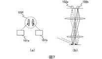
照明部101a、101bおよび検出部の変形例を図7に示す。図7(a)に示すように、照明部101a、101b各々により、対物レンズ102の視野102f内で照野が互いに重ならないように照明する。図7(b)に示すように、各々の照野が結像面上で互いに重ならないように結像される。これを各々検出器106a、106bで検出する。照明部101a、101bによる照明条件(仰角、方位角、偏光状態、波長)が互いに異なるように図3において設定することで、互いに異なる複数の照明条件に対応して発生した複数の散乱光が検出器106a、106b各々にて個別に検出される。このように、複数の照明部による照野を互いに空間的に分離し、各々の照野領域を複数の検出器で個別に検出する構成をとることで、互いに異なる複数の照明条件に対応して発生した複数の散乱光分布が検出器ごとに個別に検出される
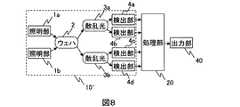
図8に図1に示した光学部の構成の変形例を示す。光学部10’は、複数の照明部1a、1b、および複数の検出部4a、4b、4c、4dからなる。照明部1aと照明部1bは互いに異なる照明光を検査対象基板2に照射する。照明部1aおよび照明光1bによる照明にて、散乱光3aおよび3bが各々発生し、各々検出部4a、4bおよび検出部4c、4dにより散乱光強度信号として検出される。検出した散乱光強度信号は処理部20に入力される。処理部20は入力された複数の散乱光強度信号に基づき欠陥情報を出力する。出力部40は処理部20より得られた欠陥情報を出力する。A modification of the
図2に示した装置構成において、検出器106a、106bとして、複数の光学成分を一括に検出可能な検出器を用いることで、図8に示した構成が実現される。複数の光学成分を一括に検出可能な検出器の例を図9に示す。図9(a)は、偏光ビームスプリッタ601により散乱光を偏光状態で分離し、検出器603a、603b各々で検出する構成である。任意の変更を選択するための波長板602a、602bが必要に応じて設置される。偏光ビームスプリッタ601をダイクロイックミラーなど波長選択機能を持つ光学素子に置き換えれば3板式CCDセンサと同等の構成となり、これを用いれば複数波長を含む散乱光を波長ごとに分離して個別に検出することができる。図9(b)は、検出器の受光画素ごとに異なる偏光状態を検出することで、互い偏光成分の異なる複数の検出信号を得る検出器の例である。線状に配列した受光画素611にて、画素毎に互いに異なる2種類の偏光を検出するよう、交互に偏光子が配置されている。このような受光器は、特許第3325825号に述べられている方法などで作成した偏光子アレイをリニアセンサの画素に合わせて貼り付けることで実現される。リニアCCDセンサとして図9(b)に示したように、奇数番目画素の信号を片側の水平転送レジスタ612に、偶数番目画素の信号をもう一方の水平転送レジスタ613に出力する構成のものを用いれば、各々のレジスタの出力が偏光成分ごとの検出信号に対応する。図9(a)の構成は図9(b)と比較して高解像度が実現できる特徴がある。一方、図9(b)の構成は、センサが1つで済むため安価に実現できる特徴がある。 In the apparatus configuration shown in FIG. 2, the configuration shown in FIG. 8 is realized by using a detector capable of detecting a plurality of optical components at once as the
図8の構成を実現する別の装置構成例を図10に示す。照明部101c、対物レンズ102、フィルタ部104c、結像レンズ105c、検出部106c、ステージ駆動部152、X-Y-Z-θステージ152が光学部10を構成する。他の構成は図2に示した装置の構成例と共通である。本構成により、照明条件および検出条件を時間的に切替えることで、単一の光源および単一の検出器を用いて図8の構成が実現される。 FIG. 10 shows another device configuration example that realizes the configuration of FIG. The
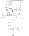
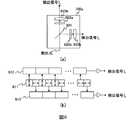
照明条件および検出条件を時間的に切替える方法の具体例について図11を用いて説明する。図11(a)は照明条件を切替える方法の具体例を示す。光源1011cとして周期的にストロボ発光するパルスレーザあるいはフラッシュランプを用いる。偏光変調素子1012cは、光源のストロボ発光の周期またはその整数倍の周期に合わせて、与える位相差を時間的に変化させるもの、例えば電気光学素子、磁気光学素子、音響光学素子、液晶素子などを用いる。偏光変調素子1012cにより、光源から出た周期的なパルス光の偏光状態が時間的に切り替わる。偏光ビームスプリッタ1013cによって偏光状態に応じて光路を分岐することで、パルス光の通る光路が時間的に切り替わる。これにより、偏光状態、照明方位、照明入射角などを時間的に切り替えながら同一箇所が照明される。図3に示した照明部の構成において、位相板1013、1014の代わりに偏光変調素子を用いて偏光状態を切替え、ミラーM1、M2の代わりに偏光ビームスプリッタを用いて偏光状態による光路の分離をすることによっても、照明条件を時間的に切替えるという点において同等の機能が実現できることは自明である。検出側にも空間変調素子104cを用いて、透過する光の偏光分布、位相分布、強度分布を時間的に切替えることで、検出する光学条件を時間的に切替えることができる。空間変調素子104cとしては、液晶素子、電気光学素子、磁気光学素子、音響光学素子、マイクロミラーデバイス、GLV(グレーティングバルブ)、機械的に駆動する遮光板などが用いられる。 A specific example of a method for temporally switching the illumination condition and the detection condition will be described with reference to FIG. FIG. 11A shows a specific example of a method for switching illumination conditions. As the light source 1011c, a pulse laser or a flash lamp that periodically emits strobe light is used. The
図11(b)に、パルス照明出力、照明条件(例として照明方位)、検出条件(例として検出する偏光成分)、検出器の露光のON/OFFの時間的関係の例を、横軸を時間軸として示す。ステージ駆動部151が出す同期信号を基準とし、照明がパルス的に発光し、照明方位、検出偏光が切り替わり、それぞれのパルス光に対する散乱光分布が単一の検出器で各々個別に検出される。照明条件をN通り(N=1、2、・・・)、検出条件をM通り(M=1、2、・・・)とすると、最大N×M通りの光学条件の組合せに対応する検出信号が得られる。 FIG. 11B shows an example of the temporal relationship of pulse illumination output, illumination conditions (illumination direction as an example), detection conditions (polarization component to be detected as an example), detector exposure ON / OFF, and the horizontal axis. Shown as time axis. Based on the synchronization signal output from the
図12に図1に示した光学部の構成の別の変形例を示す。図12は照明部による照明にて発生した散乱光を複数の検出部で検出する構成である。照明部は複数の照明条件で検査対象物の同一箇所を同時に照明するか、あるいは単一の照明条件にて照明する。発生する散乱光分布は一通りであり、これを複数の検出部で検出し、複数の検出信号を得る。本構成においては、照明部による照明条件を時間的(図11)あるいは空間的(図7)に切替える、あるいは波長で分離する(図3)構成を備えず、装置が安価に構成できるメリットがある。 FIG. 12 shows another modification of the configuration of the optical unit shown in FIG. FIG. 12 shows a configuration in which scattered light generated by illumination by the illumination unit is detected by a plurality of detection units. The illumination unit illuminates the same part of the inspection object simultaneously under a plurality of illumination conditions, or illuminates under a single illumination condition. The generated scattered light distribution is one way, and this is detected by a plurality of detection units to obtain a plurality of detection signals. In this configuration, there is an advantage that the apparatus can be configured at low cost without providing a configuration in which the illumination conditions by the illumination unit are switched temporally (FIG. 11) or spatially (FIG. 7) or separated by wavelength (FIG. 3). .
図13(a)に、前処理部21の構成を示す。互いに異なる複数の光学条件各々で得られた検出信号が前処理部21に入力される。ここでは検出信号が2つの場合を説明する。位置合せ部211にて、一つの検出信号を基準とし、それに対しその他の検出信号を補正して位置合せを行う。予め定めた時間間隔あるいは位置間隔ごとに、基準の検出信号とその他の検出信号とを比較して、補正すべき位置ずれ量を算出する。比較の方法としては、所定の範囲で切り出した信号間の相関値や差の絶対値和などを用いる。比較対象とする信号として、光学条件の違いによる信号強度の差異を吸収するよう元の検出信号強度を正規化あるいは2値化した値や、検出信号にフィルタを適用して抽出したエッジ位置、あるいは信号強度勾配方向に対応する符号などを用いることで、よりロバストな位置合せが可能となる。時間的な複数検出器間の位置ずれが小さい場合には、あらかじめ同一箇所の検出信号を複数の検出器で得て位置ずれ量を算出しておき、それに基づいて位置合せを行えば、前記のような実時間での位置合せは不要となる。 FIG. 13A shows the configuration of the
位置合せをした後の検出信号は、各々特徴量抽出部212a、212bに入力される。特徴量抽出部212a、212bにて、検出信号が処理され、1つの検出信号に対して対応する座標ごとに1つあるいは複数の画像特徴量の値が出力される。特徴量としてはその画素の特徴を表すものであればよい。その一例としては、明るさ(信号強度そのもの)、コントラスト、濃淡差、近傍画素の明るさ分散値、相関係数、近傍画素との明るさの増減、2次微分値などがある。 The detection signals after the alignment are input to the feature
図13(b)に、前処理部21の別の構成例を示す。図13(a)と異なる部分を説明する。検査対象物の上に繰返し同じパターンが形成されている場合、繰返しの1つの単位に含まれる信号を蓄積しておき、次の繰返しに現れる同一箇所と比較処理することで、欠陥を強調することができる。位置合せをした後の検出信号を、遅延部213aに蓄積し、次の繰返しに現れる同一箇所と位置合せ部214aにて位置を合わせることで、同一パターンが形成されるべき2箇所の信号が得られ、これらが特徴量演算部212aに入力される。遅延部213aに蓄積された信号を参照信号と呼ぶ。特徴量抽出部212aにて、検出信号と対応する位置の参照信号が合せて処理され、座標ごとに1つあるいは複数の画像特徴量の値が出力される。特徴量の一例としては、検出信号の明るさ(信号強度そのもの)、コントラスト、濃淡差、近傍画素の明るさ分散値、相関係数、近傍画素との明るさの増減、2次微分値、あるいはこれらの値の参照信号との差分絶対値あるいは符号付き差分などがある。 FIG. 13B shows another configuration example of the
図14(a)に判定部23の構成を示す。判定部23は欠陥判定処理部231からなる。欠陥判定処理部231は、複数の特徴量の入力に基づき、欠陥判定処理を行い、欠陥情報を出力する。欠陥判定処理部231において行われる、複数の特徴量に基づく欠陥判定の方法について図15を用いて説明する。 FIG. 14A shows the configuration of the
図15(a)に、特徴量が2つ(特徴量A、特徴量B)の場合の欠陥判定方法の一例を示す。処理対象領域の範囲内の各座標について、特徴量Aと特徴量Bを2軸にとってプロットした散布図が図15(a)である。 FIG. 15A shows an example of a defect determination method when there are two feature quantities (feature quantity A and feature quantity B). FIG. 15A is a scatter diagram in which the feature amount A and the feature amount B are plotted on two axes for each coordinate within the range of the processing target region.
処理対象領域とは、処理の単位とする領域であり、図16に半導体ウェハあるいは半導体ウェハを製造するのに用いるレチクルを検査対象とする場合の例を示す。欠陥判定処理部231にメモリを多く備えれば、ダイ全領域を処理単位とすることが可能である。処理単位の領域が広ければ統計処理の対象となるサンプル数が多くなるため、欠陥判定の信頼度が向上する。あるいは、検査対象物を走査する中で、順次取込まれる画像を逐次切り出した領域を処理単位とすれば、比較的少ないメモリで実行できる。あるいは、ダイ内で傾向の似た領域を切り出して処理単位とすれば、欠陥以外の正常部分の特徴量のばらつきが小さくなり、欠陥検出感度向上に有利である。あるいは、複数ダイにわたって各ダイ内で対応する領域を切り出して処理単位としても、欠陥以外の正常部分の特徴量のばらつきが小さくなり、欠陥検出感度向上に有利である。 The processing target area is an area as a unit of processing, and FIG. 16 shows an example in which a semiconductor wafer or a reticle used for manufacturing a semiconductor wafer is an inspection target. If the defect
欠陥部以外の正常部は、同様の物理的特徴すなわち形状あるいは材質などを備えた部分が、処理対象領域内に複数存在することが期待される。それに対し、欠陥部は正常部以外の特異な点であり、処理対象領域内に同様の物理的特徴を備えた部分が存在する確率が低い。従って、図15(a)に示した散布図において、複数の位置に対応する散布図上の点が近くに集まればその位置は正常部であり、ある位置に対応する散布図上の点が他の多数の点の集まりから外れて孤立していればその位置が欠陥部であると判定することで、欠陥判定がなされる。図15(b)はより多数の特徴量を使った場合の例を示す。2つの特徴量を用いた場合と同様の考え方で、N個の特徴量を用いた場合は、散布図がN次元空間となり、N次元空間における距離の大小をもとに少数で孤立した点が欠陥と判定される。 The normal part other than the defective part is expected to have a plurality of parts having similar physical characteristics, that is, shapes or materials, in the processing target area. On the other hand, the defective part is a peculiar point other than the normal part, and the probability that a part having the same physical characteristic exists in the processing target region is low. Therefore, in the scatter diagram shown in FIG. 15A, if points on the scatter diagram corresponding to a plurality of positions are gathered nearby, the position is a normal part, and the points on the scatter diagram corresponding to a certain position are other points. If the position is isolated from the collection of a large number of points, it is determined that the position is a defective portion, thereby determining the defect. FIG. 15B shows an example in which a larger number of feature quantities are used. In the same way as when two feature quantities are used, when N feature quantities are used, the scatter diagram becomes an N-dimensional space, and there are a small number of isolated points based on the distance in the N-dimensional space. Determined as a defect.
図15(c)は、多数の特徴量による散布図を2次元に圧縮したものを示す。複数の特徴量を演算した値を軸にとることに対応する。これにより外れ値を欠陥とする判定処理の負荷が軽減できる。複数の特徴量の演算には、複数の特徴量の中から欠陥判定に有効な特徴量を選択すること、あるいは複数の特徴量の線形結合によりそれらの影響を重み付けして抽出することなどが含まれる。使用する特徴量の選択や重み付けは、散布図上で欠陥部に対応する点が正常部に対応する点の集合に対して離れたり、あるいは特徴的な分布を示したりすることで、欠陥部の判別がしやすくなるようになされる。欠陥部は正常部に対し、その形状(凹凸、周囲の縦構造・横構造、周期性、方向性)、材質、あるいは大きさなどに関して物理的、光学的、あるいは統計的な特性に特徴を持つ。このような欠陥部の特徴すなわち欠陥部の正常部との差異は、照明に対する応答である散乱光分布に情報として含まれ、検出部にて検出信号としてその情報の一部が検出され、さらに特徴量抽出部にて画像特徴量として一部が検出される。欠陥を高感度に検出するには、欠陥部の特徴が散乱光分布により多く表れるような照明条件、あるいは散乱光分布に表れた欠陥部の特徴を逃さず捉える検出条件、さらに画像上に現れる欠陥部の特徴をよりよく抽出する特徴量抽出条件を備えることが必要である。前述の照明部、検出部、特徴量抽出部の構成によれば、互いに異なる複数の照明条件、検出条件、特徴量抽出条件の組合せに対応する複数の特徴量を一度に検出することができるため、単一の照明条件、検出条件、あるいは特徴量抽出条件しか備えない構成と比較して、欠陥部の特徴を捉えられる可能性が高く、さらに、一度に検出した複数の特徴量の中から図15(c)に示したような方法で有効な照明条件、検出条件、あるいは画像処理条件に対応する特徴量あるいは特徴量の組合せを選択することで、散布図上の分布として欠陥部の特徴が表れるため、それに基づいて欠陥を判定することで、欠陥を高感度、高捕捉率で検出することができる。 FIG. 15C shows a two-dimensionally compressed scatter diagram with a large number of features. This corresponds to taking the value obtained by calculating a plurality of feature values as an axis. Thereby, it is possible to reduce the load of determination processing in which an outlier is a defect. Calculation of multiple feature values includes selecting effective feature values for defect determination from multiple feature values, or extracting the weighted effects by linearly combining multiple feature values. It is. The selection and weighting of the feature quantity to be used is based on the fact that the point corresponding to the defective part on the scatter diagram is separated from the set of points corresponding to the normal part or shows a characteristic distribution. It is made easier to discriminate. Defects are characterized by physical, optical, or statistical characteristics with respect to the normal part in terms of shape (unevenness, surrounding vertical / horizontal structure, periodicity, directionality), material, or size. . Such a feature of the defective portion, that is, a difference from the normal portion of the defective portion is included as information in the scattered light distribution that is a response to illumination, and a part of the information is detected as a detection signal by the detection unit. A part is detected as an image feature amount by the amount extraction unit. In order to detect defects with high sensitivity, the illumination conditions in which the features of the defect part appear more in the scattered light distribution, the detection conditions for capturing the defect part feature in the scattered light distribution without missing, and the defects that appear on the image It is necessary to provide a feature amount extraction condition for better extracting the feature of the part. According to the configuration of the illumination unit, the detection unit, and the feature amount extraction unit, a plurality of feature amounts corresponding to a combination of a plurality of different illumination conditions, detection conditions, and feature amount extraction conditions can be detected at a time. Compared to a configuration with only a single illumination condition, detection condition, or feature quantity extraction condition, there is a higher possibility that the feature of the defective part will be captured. By selecting a feature amount or a combination of feature amounts corresponding to effective illumination conditions, detection conditions, or image processing conditions by the method as shown in FIG. 15C, the feature of the defective portion is distributed as a distribution on the scatter diagram. Since it appears, it is possible to detect the defect with high sensitivity and high capture rate by determining the defect based on it.
図15(c)(d)(e)は、互いに異なる条件間の特徴量の変化により欠陥を判定する方法を示す。図15(c)の散布図に対し、図15(d)は図15(c)とは異なる特徴量、あるいは特徴量の重み付けによる組合せを2軸に取った散布図を示す。図15(e)に示すように、図15(c)と(d)との間の特徴量の変化量をプロットすることで、欠陥部と正常部との分布を引き離し、欠陥を判定することも可能である。この方法は例えば、ある照明条件Aでの欠陥部あるいは正常部の散乱光分布の振る舞いと、それと異なる照明条件Bでの散乱光分布の振る舞いが大きく異なるような場合に有効であり、照明条件Aに対応する特徴量を図15(c)のf、gで選択し、照明条件Bに対応する特徴量を図15(d)のf’、g’で選択し、それらの間の散布図上の変化量を図15(e)のようにプロットすればよい。 FIGS. 15C, 15D, and 15E show a method for determining a defect based on a change in feature amount between different conditions. In contrast to the scatter diagram of FIG. 15 (c), FIG. 15 (d) shows a scatter diagram with two axes of feature amounts different from those in FIG. 15 (c) or combinations by weighting of feature amounts. As shown in FIG. 15E, by plotting the amount of change in the feature amount between FIGS. 15C and 15D, the distribution between the defective portion and the normal portion is separated to determine the defect. Is also possible. This method is effective when, for example, the behavior of the scattered light distribution in a defective part or a normal part under a certain illumination condition A and the behavior of the scattered light distribution under a different illumination condition B are significantly different. 15C is selected by f and g in FIG. 15C, and feature quantities corresponding to the illumination condition B are selected by f ′ and g ′ in FIG. The amount of change may be plotted as shown in FIG.
欠陥部の特徴を顕在化するのに有効な照明条件、検出条件の一例として、例えばX方向とY方向に関して対称的な形状を持つ正常部の中にX方向に長くY方向に短い形状的特徴を持つ欠陥部が存在する場合には、X方向に対し垂直なY方向の方位から照明光を照射する照明条件と、上方に出る散乱光を検出するような検出条件が有効である。この場合、正常部の散乱光分布に対して欠陥部の散乱光分布は上方にて散乱強度が強くなり、欠陥部の特徴が正常部より強い輝度信号として検出される。また、方向性のある欠陥には、その方向性に対応した偏光成分を持つ照明条件、あるいはその方向性に対応した検光状態を持つ検出条件を選択することも有効である。これらの例のように、欠陥部の特徴を顕在化するのに有効な照明条件、検出条件、特徴量抽出条件が明らかな場合は、用いる照明条件、検出条件、特徴量抽出条件をあらかじめ絞っておくか、あるいは図15(c)に示したように検出した特徴量の中で判定に使用するものをあらかじめ絞っておけば、照明、検出、特徴量抽出、あるいは欠陥判定の負荷が小さくなり、検査を短時間で行うことが可能となる。一方、有効な条件が明らかでない場合においても、前述の構成により一度に検出した複数の特徴量を様々な組合せあるいは重み付けで用いて判定処理をし、それらによる欠陥判定結果を比較し、適した結果を出力する判定処理方法を選択することで、欠陥を高感度、高捕捉率で検出することができる。上記の適した結果を出力する判定方法を選択するために必要な手順と情報の入出力については、図17を用いて後述する。 As an example of illumination conditions and detection conditions effective for revealing the features of the defective part, for example, in a normal part having a symmetrical shape with respect to the X direction and the Y direction, a geometric feature that is long in the X direction and short in the Y direction In the case where there is a defect portion having, illumination conditions for irradiating illumination light from a direction in the Y direction perpendicular to the X direction and detection conditions for detecting scattered light emitted upward are effective. In this case, the scattered light distribution of the defective part has a higher scattering intensity in the upper part than the scattered light distribution of the normal part, and the characteristic of the defective part is detected as a luminance signal stronger than that of the normal part. It is also effective to select an illumination condition having a polarization component corresponding to the directionality or a detection condition having a light detection state corresponding to the directionality for a directional defect. As in these examples, if the illumination conditions, detection conditions, and feature quantity extraction conditions that are effective for revealing the features of the defective part are clear, the illumination conditions, detection conditions, and feature quantity extraction conditions to be used should be narrowed down in advance. If the features to be used for determination are narrowed down in advance as shown in FIG. 15C, the load of illumination, detection, feature extraction, or defect determination is reduced. Inspection can be performed in a short time. On the other hand, even when the effective conditions are not clear, a plurality of feature amounts detected at a time by the above-described configuration are used in various combinations or weightings, and the determination results are compared, and suitable results are compared. By selecting a determination processing method that outputs, defects can be detected with high sensitivity and high capture rate. The procedure and information input / output necessary for selecting the determination method for outputting the suitable result will be described later with reference to FIG.
欠陥判定部23の別の構成例を図14(b)を用いて説明する。前述の特徴量抽出部より出力された複数の特徴量のうち一部(図14(b)では特徴量1と特徴量3)が欠陥判定処理部231’に入力される。欠陥判定処理部231’では、前述の欠陥判定処理231における欠陥判定処理と同様の方法で欠陥判定が行われる。ただし欠陥判定処理部231’では、欠陥判定処理部231より低い判断基準、しきい値による欠陥判定がなされ、欠陥部と正常部が入り混じった集合すなわち欠陥候補の集合の情報(対応する座標)232が出力される。後段の擬似欠陥除去処理部233では欠陥候補の集合の座標232と、前述の特徴量抽出部より出力された複数の特徴量が入力され、擬似欠陥判定処理が行われる(図15(f))。擬似欠陥判定処理は、欠陥候補の集合のみを対象として、各々の欠陥候補の特徴量にもとづいて、前述の欠陥判定処理部231と同様の処理を行い、欠陥部の判定、ここではすなわち欠陥候補に含まれる正常部(擬似欠陥)の除去がなされる。前述の図14(a)の構成では、検査対象物上の多数の位置に関して多数の特徴量にもとづいた欠陥判定を行うため、処理負荷が大きくなるのに対し、図14(b)の構成では、前段の欠陥判定処理部231’にて、検査対象物上の多数の位置に関して少数の特徴量をもとに欠陥候補位置を絞り込み、絞り込んだ後の少数の欠陥候補位置に関してのみ多数の特徴量にもとづく欠陥判定を行うことで、正味の処理負荷が低減する。 Another configuration example of the
検査条件(光学条件、特徴量抽出条件、および欠陥判定処理方法)設定のフローを図17に示す。ユーザの入力などに基づき、光学条件の組合せ(セット)があらかじめ備えられた複数の光学条件(照明条件および検出条件)の組合せの中から選択される(F1)。次に、ユーザの入力などに基づき、光学条件および特徴量抽出条件および欠陥判定処理方法を決めるために行う試し検査の対象とする領域が設定される(F2)。試し検査対象領域を含む領域が走査され、選択された光学条件セットにて検出信号が検出される(F3)。検出信号が図15に示したような1種類以上の処理方法にて処理される(F4)。試し検査対象領域内の欠陥候補のリストと、各々の位置や特徴量を含めた欠陥候補に関する情報が表示される(F5)。欠陥候補リストに含まれる欠陥候補位置が、試し検査と同等以上の解像度で、装置に備えられたレビュー顕微鏡によりレビューされる、すなわちその位置の静止画像が取得される。欠陥候補位置の静止画像を装置に備えられたレビュー顕微鏡を用いて得るほかに、試し検査の走査時に得られた画像を記憶部に蓄えておいて用いても、装置が出力した欠陥候補位置をもとに欠陥レビューSEM、測長SEM、あるいは卓上SEM、AFMなどにより得た画像を用いてもよい(F6)。欠陥候補ごとに、レビューで得られた画像が表示部に表示され、画像を元にした判断によりそれが実際の欠陥であるかそうでないかが教示入力される(F7)。教示結果にもとづいて、欠陥判定処理のパラメータを変更し、再処理がなされる(F8)。再処理の結果が表示部に出力され、欠陥検出個数、欠陥捕捉率(欠陥と教示された欠陥候補個数に対して、再処理で欠陥として検出された個数の比率)、擬似欠陥の割合(再処理で欠陥として検出された個数のうち、欠陥でないと教示された欠陥候補個数の割合)などが製造工程管理上許容範囲内であるか判定がなされる(F9)。許容範囲内であれば、そこで検査条件が決定される(F11)。許容範囲外であれば、試し検査の条件と結果(各欠陥候補について位置情報、教示結果、光学条件・特徴量抽出条件ごとに対応する特徴量)が記憶部に保存され、F1に戻り、過去の試し検査の条件と結果と照らし合わせて別の光学条件セットが選択され、再度試し検査が行われる。 FIG. 17 shows a flow of setting inspection conditions (optical conditions, feature amount extraction conditions, and defect determination processing method). Based on a user input or the like, a combination (set) of optical conditions is selected from a plurality of combinations of optical conditions (illumination conditions and detection conditions) prepared in advance (F1). Next, based on a user input or the like, a region to be subjected to a trial inspection performed to determine an optical condition, a feature extraction condition, and a defect determination processing method is set (F2). An area including the trial inspection target area is scanned, and a detection signal is detected in the selected optical condition set (F3). The detection signal is processed by one or more processing methods as shown in FIG. 15 (F4). A list of defect candidates in the trial inspection target area and information on the defect candidates including their positions and feature amounts are displayed (F5). A defect candidate position included in the defect candidate list is reviewed by a review microscope provided in the apparatus with a resolution equal to or higher than that of the trial inspection, that is, a still image at that position is acquired. In addition to obtaining a still image of the defect candidate position using the review microscope provided in the apparatus, the defect candidate position output by the apparatus can be obtained even if the image obtained during the scan of the trial inspection is stored in the storage unit and used. An image obtained by a defect review SEM, a length measurement SEM, a desktop SEM, an AFM, or the like may be used (F6). For each defect candidate, the image obtained in the review is displayed on the display unit, and whether or not it is an actual defect is input based on the determination based on the image (F7). Based on the teaching result, the parameter of the defect determination process is changed, and reprocessing is performed (F8). The result of the reprocessing is output to the display unit, and the number of detected defects, the defect capture rate (the ratio of the number of defects detected as a defect to the number of defect candidates taught as defects), the ratio of pseudo defects (recycled) It is determined whether or not the ratio of the number of defect candidates taught as non-defect among the number detected as defects in the process is within an allowable range in manufacturing process management (F9). If it is within the allowable range, the inspection condition is determined there (F11). If it is outside the allowable range, the condition and result of the trial inspection (position information, teaching result, and feature quantity corresponding to each optical condition / feature quantity extraction condition for each defect candidate) are stored in the storage unit, and the process returns to F1. Another optical condition set is selected in light of the test inspection conditions and results, and the test inspection is performed again.
以上、本発明者によってなされた発明を実施形態に基づき具体的に説明したが、本発明は上記実施形態に限定されるものではなく、その要旨を逸脱しない範囲で種々変更可能であることはいうまでもない。 As mentioned above, the invention made by the present inventor has been specifically described based on the embodiment. However, the present invention is not limited to the above embodiment, and various modifications can be made without departing from the scope of the invention. Not too long.
1…光源、
1a、1b…照明部
2…ウェハ
3a、3b…散乱光
4a、4b…検出部
10、10’、10’’…光学部
20…処理部
21…前処理部
22a〜d…特徴量
23…判定部
40…出力部
101a、101b…照明系
102…対物レンズ
103…光路分岐素子
104a、104b…フィルタ部
105a、105b…結像レンズ
106a、106b…検出器
107…オートフォーカス照明部
108…オートフォーカス検出部
151…ステージ駆動部
152…X-Y-Z-θステージ152
301…全体制御部
302…表示部
303…演算部
304…記憶部
1010…照明光源
1010a、1010b…光源
1011…アッテネータ
1012…偏光板
1013…位相板
1014…位相板
1015…ビームエキスパンダ
1016…光路
1017…ビーム成型光学素子
M1〜M7…ミラー1 ... light source,
1a, 1b ... Lighting section
2 ... wafer
3a, 3b ... scattered light
4a, 4b ... Detector
10, 10 ', 10''... optics
20 ... Processing section
21 ... Pre-processing section
22a to d ... Features
23 ... Judgment part
40 ... Output section
101a, 101b ... Lighting system
102 ... Objective lens
103: Optical path branching element
104a, 104b ... Filter section
105a, 105b ... Imaging lens
106a, 106b ... Detector
107… Autofocus lighting
108… Auto focus detector
151… Stage drive unit
152 ... XYZ-
301 ... Overall control unit
302 ... Display section
303… Calculation unit
304: Memory unit
1010 ... Illumination light source
1010a, 1010b ... Light source
1011 ... Attenuator
1012 ... Polarizing plate
1013… Phase plate
1014 Phase plate
1015 ... Beam expander
1016: Light path
1017 ... Beam shaping optical element
M1 ~ M7 ... Mirror
Claims (8)
Translated fromJapanese前記所定領域において、前記複数の光学条件に対応して生じる複数の散乱光分布の各々につき、所定の方位角範囲および所定の仰角範囲に伝播する散乱光成分のうち正反射光成分を除いた光成分のみを受光器に導き複数の画像として検出する検出工程と、
前記検出された複数の画像から複数の画像特徴量を抽出し、前記抽出された複数の画像特徴量の特徴量空間における分布から正常部とは異なる欠陥部を欠陥として検出する欠陥検出工程と、
を有することを特徴とする欠陥検査方法。An illumination step of irradiating a predetermined region on the inspection target substrate with light emitted from the light source under a plurality of predetermined optical conditions;
Light obtained by removing the specularly reflected light component from the scattered light component propagating to a predetermined azimuth angle range and a predetermined elevation angle range for each of the plurality of scattered light distributions generated corresponding to the plurality of optical conditions in the predetermined region. A detection process in which only components are guided to a light receiver and detected as a plurality of images;
A defectdetection step of extracting a plurality of image feature amounts from the plurality of detected images, anddetecting a defectportion different from a normal portionas a defectfrom a distribution in the feature amount space of the extracted plurality of image feature amounts;
A defect inspection method characterized by comprising:
前記照明工程では、前記複数の光学条件として互いに異なる波長の光を照射することを特徴とする欠陥検査方法。The defect inspection method according to claim 1,
In the illumination step, the defect inspection method is characterized by irradiating light having different wavelengths as the plurality of optical conditions.
前記照明工程では、前記複数の光学条件として互いに異なる偏光状態の光を照射することを特徴とする欠陥検査方法。A defect inspection method according to claim 1 or 2,
In the illumination step, the defect inspection method is characterized by irradiating light having different polarization states as the plurality of optical conditions.
前記照明工程では、前記複数の光学条件の光を同時に照射することを特徴とする欠陥検査方法。A defect inspection method according to any one of claims 1 to 3,
In the illumination step, the defect inspection method is characterized by simultaneously irradiating light having the plurality of optical conditions.
前記照明工程では、前記光源としてランプ光源を用いることを特徴とする欠陥検査方法。A defect inspection method according to any one of claims 1 to 4,
In the illumination process, a lamp light source is used as the light source.
前記検出工程では、空間フィルタを用いて前記散乱光成分の一部を遮光あるいは透過させた後に前記受光器に導くことを特徴とする欠陥検査方法。A defect inspection method according to any one of claims 1 to 5,
In the detecting step, a part of the scattered light component is shielded or transmitted using a spatial filter and then guided to the light receiver.
前記照明工程では、照野が線状となるように光を照射することを特徴とする欠陥検査方法。A defect inspection method according to any one of claims 1 to 6,
In the illumination step, the defect inspection method is characterized by irradiating light so that the illumination field is linear.
前記照明工程では、シリンドリカルレンズを用いて前記照野が線状となるような光を照射することを特徴とする欠陥検査方法。The defect inspection apparatus according to claim7 ,
In the illumination step, a defect inspection method characterized by irradiating the illumination field with a linear lens using a cylindrical lens.
Priority Applications (2)
| Application Number | Priority Date | Filing Date | Title |
|---|---|---|---|
| JP2007115005AJP4876019B2 (en) | 2007-04-25 | 2007-04-25 | Defect inspection apparatus and method |
| US12/109,363US8274652B2 (en) | 2007-04-25 | 2008-04-25 | Defect inspection system and method of the same |
Applications Claiming Priority (1)
| Application Number | Priority Date | Filing Date | Title |
|---|---|---|---|
| JP2007115005AJP4876019B2 (en) | 2007-04-25 | 2007-04-25 | Defect inspection apparatus and method |
Related Child Applications (1)
| Application Number | Title | Priority Date | Filing Date |
|---|---|---|---|
| JP2011258430ADivisionJP5452571B2 (en) | 2011-11-28 | 2011-11-28 | Defect inspection method and defect inspection apparatus |
Publications (2)
| Publication Number | Publication Date |
|---|---|
| JP2008268141A JP2008268141A (en) | 2008-11-06 |
| JP4876019B2true JP4876019B2 (en) | 2012-02-15 |
Family
ID=40047826
Family Applications (1)
| Application Number | Title | Priority Date | Filing Date |
|---|---|---|---|
| JP2007115005AExpired - Fee RelatedJP4876019B2 (en) | 2007-04-25 | 2007-04-25 | Defect inspection apparatus and method |
Country Status (2)
| Country | Link |
|---|---|
| US (1) | US8274652B2 (en) |
| JP (1) | JP4876019B2 (en) |
Families Citing this family (49)
| Publication number | Priority date | Publication date | Assignee | Title |
|---|---|---|---|---|
| US8385997B2 (en)* | 2007-12-11 | 2013-02-26 | Tokitae Llc | Spectroscopic detection of malaria via the eye |
| US8585567B2 (en)* | 2007-12-11 | 2013-11-19 | Tokitae Llc | Systems, devices, and methods including paramagnetic oscillation, rotation and translation of hemozoin asymmetric nanoparticles in response to multi-harmonic optical detection of the presence of hemozoin |
| JP5156413B2 (en)* | 2008-02-01 | 2013-03-06 | 株式会社日立ハイテクノロジーズ | Defect inspection method and defect inspection apparatus |
| JP5022959B2 (en)* | 2008-03-24 | 2012-09-12 | 株式会社日立製作所 | Defect inspection system using catadioptric objective lens |
| JP5174535B2 (en)* | 2008-05-23 | 2013-04-03 | 株式会社日立ハイテクノロジーズ | Defect inspection method and apparatus |
| JP2010190722A (en)* | 2009-02-18 | 2010-09-02 | Hitachi High-Technologies Corp | Method and device for inspecting defect |
| JP2010236966A (en)* | 2009-03-31 | 2010-10-21 | Hitachi High-Technologies Corp | Defect inspection apparatus and method |
| JP2010236968A (en)* | 2009-03-31 | 2010-10-21 | Hitachi High-Technologies Corp | Inspection method and inspection apparatus |
| JP5237874B2 (en)* | 2009-04-24 | 2013-07-17 | 株式会社日立ハイテクノロジーズ | Defect inspection method and defect inspection apparatus |
| JP5331586B2 (en)* | 2009-06-18 | 2013-10-30 | 株式会社日立ハイテクノロジーズ | Defect inspection apparatus and inspection method |
| JP5171744B2 (en)* | 2009-07-01 | 2013-03-27 | 株式会社日立ハイテクノロジーズ | Defect inspection method and apparatus |
| JP2011047724A (en)* | 2009-08-26 | 2011-03-10 | Hitachi High-Technologies Corp | Apparatus and method for inspecting defect |
| JP5216752B2 (en)* | 2009-11-18 | 2013-06-19 | 株式会社日立ハイテクノロジーズ | Defect detection method, defect detection apparatus, and defect observation apparatus provided with the same |
| JP2011122990A (en)* | 2009-12-14 | 2011-06-23 | Hitachi High-Technologies Corp | Defect inspection apparatus and defect inspection method |
| KR101021691B1 (en)* | 2009-12-28 | 2011-03-17 | 한국기계연구원 | Lens inspection device |
| JP5292323B2 (en) | 2010-01-25 | 2013-09-18 | 株式会社リガク | Micro X-ray measuring device |
| WO2011100065A2 (en)* | 2010-02-10 | 2011-08-18 | Tokitae Llc | Systems, devices, and methods including a dark-field reflected-illumination apparatus |
| US8781184B2 (en)* | 2010-02-10 | 2014-07-15 | Tokitae Llc | Systems, devices, and methods for detection of malaria |
| US9044141B2 (en)* | 2010-02-10 | 2015-06-02 | Tokitae Llc | Systems, devices, and methods including a dark-field reflected-illumination apparatus |
| KR101830679B1 (en)* | 2010-07-29 | 2018-02-22 | 삼성디스플레이 주식회사 | Apparatus for testing a display panel and method thereof |
| JP5525421B2 (en)* | 2010-11-24 | 2014-06-18 | 株式会社日立ハイテクノロジーズ | Image capturing apparatus and image capturing method |
| JP5417306B2 (en)* | 2010-11-29 | 2014-02-12 | 株式会社日立ハイテクノロジーズ | Defect inspection method and defect inspection apparatus |
| SG10201510329VA (en)* | 2010-12-16 | 2016-01-28 | Kla Tencor Corp | Wafer inspection |
| US9063097B2 (en) | 2011-02-11 | 2015-06-23 | Taiwan Semiconductor Manufacturing Company, Ltd. | Systems and methods eliminating false defect detections |
| US20130341310A1 (en)* | 2012-06-22 | 2013-12-26 | Coherent Lasersystems Gmbh & Co. Kg | Monitoring method and apparatus for excimer laser annealing process |
| US9916653B2 (en)* | 2012-06-27 | 2018-03-13 | Kla-Tenor Corporation | Detection of defects embedded in noise for inspection in semiconductor manufacturing |
| US9012862B2 (en)* | 2012-09-21 | 2015-04-21 | Industrial Technology Research Institute | Material aging test apparatus and method thereof |
| JP5993691B2 (en) | 2012-09-28 | 2016-09-14 | 株式会社日立ハイテクノロジーズ | Defect inspection apparatus and defect inspection method |
| US9234836B2 (en)* | 2012-11-15 | 2016-01-12 | Fraunhofer-Gesellschaft Zur Foerderung Der Angewandten Forschung E.V. | Measurement of a fiber direction of a carbon fiber material and fabrication of an object in carbon fiber composite technique |
| JP5997039B2 (en)* | 2012-12-26 | 2016-09-21 | 株式会社日立ハイテクノロジーズ | Defect inspection method and defect inspection apparatus |
| TW201430336A (en)* | 2013-01-23 | 2014-08-01 | Huang Tian Xing | Defect detection method, device and system |
| US9619876B2 (en)* | 2013-03-12 | 2017-04-11 | Kla-Tencor Corp. | Detecting defects on wafers based on 2D scatter plots of values determined for output generated using different optics modes |
| US9581554B2 (en)* | 2013-05-30 | 2017-02-28 | Seagate Technology Llc | Photon emitter array |
| JP6069133B2 (en) | 2013-08-30 | 2017-02-01 | 株式会社日立ハイテクノロジーズ | Defect inspection apparatus and defect inspection method |
| US20150120220A1 (en)* | 2013-10-29 | 2015-04-30 | Kla-Tencor Corporation | Detecting IC Reliability Defects |
| US9335276B2 (en) | 2014-03-03 | 2016-05-10 | Coherent Lasersystems Gmbh & Co. Kg | Monitoring method and apparatus for control of excimer laser annealing |
| JP6328468B2 (en)* | 2014-03-31 | 2018-05-23 | 株式会社日立ハイテクノロジーズ | Defect inspection apparatus and inspection method |
| JP2015224912A (en)* | 2014-05-27 | 2015-12-14 | 株式会社レイテックス | Defect measurement device and defect measurement method |
| JP6369860B2 (en)* | 2014-07-15 | 2018-08-08 | 株式会社日立ハイテクノロジーズ | Defect observation method and apparatus |
| US9625385B2 (en)* | 2015-02-24 | 2017-04-18 | Tokitae Llc | Photothermal spectroscopy systems for offset synchronous testing of flow assays and methods of using same |
| US9767548B2 (en)* | 2015-04-24 | 2017-09-19 | Kla-Tencor Corp. | Outlier detection on pattern of interest image populations |
| JP6742413B2 (en)* | 2015-12-31 | 2020-08-19 | エーエスエムエル ホールディング エヌ.ブイ. | Focusing method and apparatus for inspection system |
| JP6517734B2 (en)* | 2016-06-09 | 2019-05-22 | 列真株式会社 | Scattered light detection head |
| KR20180042649A (en)* | 2016-10-18 | 2018-04-26 | 삼성전자주식회사 | Inspection appartus of semiconductor device and driving method of the same |
| US9976969B1 (en) | 2016-10-28 | 2018-05-22 | Coherent Lasersystems Gmbh & Co. Kg | Monitoring method and apparatus for excimer-laser annealing process |
| US20180232875A1 (en)* | 2017-02-13 | 2018-08-16 | Pervacio Inc | Cosmetic defect evaluation |
| CN112485272B (en)* | 2020-12-14 | 2021-11-09 | 紫创(南京)科技有限公司 | Semiconductor detection device and detection method |
| EP4361615A4 (en)* | 2021-07-08 | 2024-10-23 | JFE Steel Corporation | INSPECTION METHOD, CLASSIFICATION METHOD, MANAGEMENT METHOD, STEEL MATERIAL MANUFACTURING METHOD, INSTRUCTION MODEL GENERATING METHOD, INSTRUCTION MODEL, INSPECTION DEVICE AND STEEL MATERIAL MANUFACTURING FACILITY |
| CN119827522B (en)* | 2025-03-17 | 2025-06-06 | 江西华视光电有限公司 | A method for detecting defects in liquid crystal display screen |
Family Cites Families (39)
| Publication number | Priority date | Publication date | Assignee | Title |
|---|---|---|---|---|
| JPH0781956B2 (en) | 1985-10-16 | 1995-09-06 | 株式会社日立製作所 | Foreign object detection device on semiconductor substrate |
| JP2609594B2 (en) | 1986-11-28 | 1997-05-14 | 株式会社日立製作所 | Defect inspection equipment |
| JPS63226937A (en)* | 1987-03-16 | 1988-09-21 | Hitachi Electronics Eng Co Ltd | Foreign object inspection device |
| JPH0786465B2 (en) | 1987-10-30 | 1995-09-20 | 株式会社日立製作所 | Foreign object detection method and apparatus |
| US4877326A (en) | 1988-02-19 | 1989-10-31 | Kla Instruments Corporation | Method and apparatus for optical inspection of substrates |
| US5076692A (en)* | 1990-05-31 | 1991-12-31 | Tencor Instruments | Particle detection on a patterned or bare wafer surface |
| DE4021541C1 (en)* | 1990-07-06 | 1991-12-19 | Fraunhofer-Gesellschaft Zur Foerderung Der Angewandten Forschung Ev, 8000 Muenchen, De | |
| JPH0491452A (en)* | 1990-08-01 | 1992-03-24 | Mitsubishi Electric Corp | Inspecting device for forming matter |
| US5317380A (en)* | 1991-02-19 | 1994-05-31 | Inspex, Inc. | Particle detection method and apparatus |
| JPH05129399A (en)* | 1991-11-01 | 1993-05-25 | Toshiba Corp | Surface attached particle detector |
| JP3275425B2 (en) | 1993-03-09 | 2002-04-15 | 株式会社日立製作所 | Defect detection apparatus and method |
| JP3435187B2 (en) | 1993-05-12 | 2003-08-11 | 株式会社日立製作所 | Defect inspection method and apparatus |
| JP3593375B2 (en) | 1995-02-07 | 2004-11-24 | 株式会社日立製作所 | Micro defect detection method and device |
| JP3686160B2 (en)* | 1995-04-10 | 2005-08-24 | 株式会社日立ハイテクノロジーズ | Wafer surface inspection method and inspection apparatus |
| WO1996039619A1 (en) | 1995-06-06 | 1996-12-12 | Kla Instruments Corporation | Optical inspection of a specimen using multi-channel responses from the specimen |
| JP2956651B2 (en)* | 1997-05-20 | 1999-10-04 | 日本電気株式会社 | Fine pattern inspection apparatus and inspection method |
| JPH11142127A (en)* | 1997-11-11 | 1999-05-28 | Topcon Corp | Wafer surface inspection method and apparatus |
| US6104481A (en) | 1997-11-11 | 2000-08-15 | Kabushiki Kaisha Topcon | Surface inspection apparatus |
| US6800859B1 (en)* | 1998-12-28 | 2004-10-05 | Hitachi, Ltd. | Method and equipment for detecting pattern defect |
| US6366352B1 (en)* | 1999-06-10 | 2002-04-02 | Applied Materials, Inc. | Optical inspection method and apparatus utilizing a variable angle design |
| JP3784603B2 (en)* | 2000-03-02 | 2006-06-14 | 株式会社日立製作所 | Inspection method and apparatus, and inspection condition setting method in inspection apparatus |
| JP3895194B2 (en)* | 2002-02-25 | 2007-03-22 | 株式会社日立ハイテクノロジーズ | Method for detecting relative dielectric constant of porous material and foreign substance inspection apparatus |
| US6833913B1 (en)* | 2002-02-26 | 2004-12-21 | Kla-Tencor Technologies Corporation | Apparatus and methods for optically inspecting a sample for anomalies |
| JP4387089B2 (en)* | 2002-08-30 | 2009-12-16 | 株式会社日立製作所 | Defect inspection apparatus and defect inspection method |
| US7116413B2 (en)* | 2002-09-13 | 2006-10-03 | Kla-Tencor Corporation | Inspection system for integrated applications |
| WO2004031753A1 (en)* | 2002-09-30 | 2004-04-15 | Applied Materials Israel, Ltd. | Inspection system with oblique viewing angle |
| US7379175B1 (en)* | 2002-10-15 | 2008-05-27 | Kla-Tencor Technologies Corp. | Methods and systems for reticle inspection and defect review using aerial imaging |
| US7123356B1 (en)* | 2002-10-15 | 2006-10-17 | Kla-Tencor Technologies Corp. | Methods and systems for inspecting reticles using aerial imaging and die-to-database detection |
| US7068363B2 (en)* | 2003-06-06 | 2006-06-27 | Kla-Tencor Technologies Corp. | Systems for inspection of patterned or unpatterned wafers and other specimen |
| JP2005158780A (en)* | 2003-11-20 | 2005-06-16 | Hitachi Ltd | Pattern defect inspection method and apparatus |
| US7471382B2 (en)* | 2004-10-04 | 2008-12-30 | Kla-Tencor Technologies Corporation | Surface inspection system with improved capabilities |
| JP4751617B2 (en)* | 2005-01-21 | 2011-08-17 | 株式会社日立ハイテクノロジーズ | Defect inspection method and apparatus |
| JP4637642B2 (en)* | 2005-05-18 | 2011-02-23 | 株式会社日立ハイテクノロジーズ | Device and method for inspecting defects between patterns |
| JP4716827B2 (en)* | 2005-09-13 | 2011-07-06 | 株式会社東京精密 | Appearance inspection apparatus and appearance inspection method |
| JP2007101401A (en)* | 2005-10-05 | 2007-04-19 | Tokyo Seimitsu Co Ltd | Visual examination device and method |
| JP4988224B2 (en)* | 2006-03-01 | 2012-08-01 | 株式会社日立ハイテクノロジーズ | Defect inspection method and apparatus |
| JP4939843B2 (en) | 2006-06-07 | 2012-05-30 | 株式会社日立ハイテクノロジーズ | Defect inspection method and apparatus |
| JP2008020374A (en) | 2006-07-14 | 2008-01-31 | Hitachi High-Technologies Corp | Defect inspection method and apparatus |
| JP5221858B2 (en)* | 2006-08-30 | 2013-06-26 | 株式会社日立ハイテクノロジーズ | Defect inspection apparatus and defect inspection method |
- 2007
- 2007-04-25JPJP2007115005Apatent/JP4876019B2/ennot_activeExpired - Fee Related
- 2008
- 2008-04-25USUS12/109,363patent/US8274652B2/ennot_activeExpired - Fee Related
Also Published As
| Publication number | Publication date |
|---|---|
| US8274652B2 (en) | 2012-09-25 |
| US20080297783A1 (en) | 2008-12-04 |
| JP2008268141A (en) | 2008-11-06 |
Similar Documents
| Publication | Publication Date | Title |
|---|---|---|
| JP4876019B2 (en) | Defect inspection apparatus and method | |
| JP5452571B2 (en) | Defect inspection method and defect inspection apparatus | |
| JP4988224B2 (en) | Defect inspection method and apparatus | |
| JP5303217B2 (en) | Defect inspection method and defect inspection apparatus | |
| JP5132982B2 (en) | Pattern defect inspection apparatus and method | |
| JP5171744B2 (en) | Defect inspection method and apparatus | |
| JP5211242B2 (en) | Dynamic illumination in optical inspection systems | |
| US9678021B2 (en) | Method and apparatus for inspecting defects | |
| JP5132866B2 (en) | Surface inspection apparatus and surface inspection method | |
| JP4600476B2 (en) | Defect inspection method and defect inspection apparatus for fine structure | |
| JP2005283190A (en) | Foreign object inspection method and apparatus | |
| JP5416600B2 (en) | Defect inspection apparatus and method | |
| US20080204736A1 (en) | Defect Inspection Method and Defect Inspection Apparatus | |
| KR101445463B1 (en) | Defect inspection method and device thereof | |
| US20080043313A1 (en) | Spatial filter, a system and method for collecting light from an object | |
| JP5276833B2 (en) | Defect inspection method and defect inspection apparatus | |
| JP5593209B2 (en) | Inspection device | |
| JPH0536726B2 (en) | ||
| JP5301293B2 (en) | Defect inspection apparatus and method | |
| JP2012163422A (en) | Inspection device |
Legal Events
| Date | Code | Title | Description |
|---|---|---|---|
| A621 | Written request for application examination | Free format text:JAPANESE INTERMEDIATE CODE: A621 Effective date:20090213 | |
| A521 | Request for written amendment filed | Free format text:JAPANESE INTERMEDIATE CODE: A523 Effective date:20090213 | |
| A977 | Report on retrieval | Free format text:JAPANESE INTERMEDIATE CODE: A971007 Effective date:20090710 | |
| A131 | Notification of reasons for refusal | Free format text:JAPANESE INTERMEDIATE CODE: A131 Effective date:20090714 | |
| A521 | Request for written amendment filed | Free format text:JAPANESE INTERMEDIATE CODE: A523 Effective date:20090911 | |
| A521 | Request for written amendment filed | Free format text:JAPANESE INTERMEDIATE CODE: A523 Effective date:20090911 | |
| A131 | Notification of reasons for refusal | Free format text:JAPANESE INTERMEDIATE CODE: A131 Effective date:20100323 | |
| A521 | Request for written amendment filed | Free format text:JAPANESE INTERMEDIATE CODE: A523 Effective date:20100524 | |
| A131 | Notification of reasons for refusal | Free format text:JAPANESE INTERMEDIATE CODE: A131 Effective date:20101130 | |
| A521 | Request for written amendment filed | Free format text:JAPANESE INTERMEDIATE CODE: A523 Effective date:20110127 | |
| TRDD | Decision of grant or rejection written | ||
| A01 | Written decision to grant a patent or to grant a registration (utility model) | Free format text:JAPANESE INTERMEDIATE CODE: A01 Effective date:20111101 | |
| A01 | Written decision to grant a patent or to grant a registration (utility model) | Free format text:JAPANESE INTERMEDIATE CODE: A01 | |
| A61 | First payment of annual fees (during grant procedure) | Free format text:JAPANESE INTERMEDIATE CODE: A61 Effective date:20111128 | |
| FPAY | Renewal fee payment (event date is renewal date of database) | Free format text:PAYMENT UNTIL: 20141202 Year of fee payment:3 | |
| R150 | Certificate of patent or registration of utility model | Ref document number:4876019 Country of ref document:JP Free format text:JAPANESE INTERMEDIATE CODE: R150 Free format text:JAPANESE INTERMEDIATE CODE: R150 | |
| S531 | Written request for registration of change of domicile | Free format text:JAPANESE INTERMEDIATE CODE: R313531 | |
| S533 | Written request for registration of change of name | Free format text:JAPANESE INTERMEDIATE CODE: R313533 | |
| R350 | Written notification of registration of transfer | Free format text:JAPANESE INTERMEDIATE CODE: R350 | |
| LAPS | Cancellation because of no payment of annual fees |