JP4875791B2 - Method and apparatus for navigation and measurement in a multidimensional image data set - Google Patents
Method and apparatus for navigation and measurement in a multidimensional image data setDownload PDFInfo
- Publication number
- JP4875791B2 JP4875791B2JP2008528361AJP2008528361AJP4875791B2JP 4875791 B2JP4875791 B2JP 4875791B2JP 2008528361 AJP2008528361 AJP 2008528361AJP 2008528361 AJP2008528361 AJP 2008528361AJP 4875791 B2JP4875791 B2JP 4875791B2
- Authority
- JP
- Japan
- Prior art keywords
- image data
- data set
- measurement
- navigation
- target
- Prior art date
- Legal status (The legal status is an assumption and is not a legal conclusion. Google has not performed a legal analysis and makes no representation as to the accuracy of the status listed.)
- Active
Links
Images


Classifications
- G—PHYSICS
- G06—COMPUTING OR CALCULATING; COUNTING
- G06T—IMAGE DATA PROCESSING OR GENERATION, IN GENERAL
- G06T19/00—Manipulating 3D models or images for computer graphics
- G—PHYSICS
- G06—COMPUTING OR CALCULATING; COUNTING
- G06T—IMAGE DATA PROCESSING OR GENERATION, IN GENERAL
- G06T2210/00—Indexing scheme for image generation or computer graphics
- G06T2210/41—Medical
- G—PHYSICS
- G06—COMPUTING OR CALCULATING; COUNTING
- G06T—IMAGE DATA PROCESSING OR GENERATION, IN GENERAL
- G06T2219/00—Indexing scheme for manipulating 3D models or images for computer graphics
- G06T2219/008—Cut plane or projection plane definition
Landscapes
- Engineering & Computer Science (AREA)
- Computer Graphics (AREA)
- Computer Hardware Design (AREA)
- General Engineering & Computer Science (AREA)
- Software Systems (AREA)
- Physics & Mathematics (AREA)
- General Physics & Mathematics (AREA)
- Theoretical Computer Science (AREA)
- Ultra Sonic Daignosis Equipment (AREA)
- Measuring And Recording Apparatus For Diagnosis (AREA)
- Investigating Or Analyzing Materials By The Use Of Ultrasonic Waves (AREA)
- Analysing Materials By The Use Of Radiation (AREA)
Abstract
Description
Translated fromJapanese本発明は、目標物の多次元画像データセット、特に、医療用イメージング方法によって取得/捕捉された目標物の多次元画像データセット内でナビゲーションと測定を行う方法及び装置に関する。 The present invention relates to a multi-dimensional image data set of a target, and more particularly to a method and apparatus for navigation and measurement within a multi-dimensional image data set of a target acquired / captured by a medical imaging method.
多くの医療技術イメージング方法、例えば超音波断層撮影法、磁気共鳴断層撮影法、又は光コヒーレンス断層撮影法(OCT)等を用いて、検査対象である目標物の三次元(3D)又は四次元(4D)の画像データセットを取得することができる。四次元のデータセットとは、複数の三次元画像のタイムシーケンスのことである。ところで、器官を表示するこのような従来の3D又は4Dの画像データセット内における方向決めは、一般に、かなり困難であり、心臓病専門医/放射線専門医又は顧問医であるユーザ側にかなりの経験が要求されるものである。 Using many medical technology imaging methods, such as ultrasonic tomography, magnetic resonance tomography, or optical coherence tomography (OCT), the three-dimensional (3D) or four-dimensional ( 4D) image data sets can be acquired. A four-dimensional data set is a time sequence of a plurality of three-dimensional images. By the way, orientation in such conventional 3D or 4D image data sets displaying organs is generally quite difficult and requires considerable experience on the part of the cardiologist / radiologist or advisor. It is what is done.
画像データセットを利用してこのデータセット内で測定及びその検証では、多くの場合、二次元の断面画像上で観察が行われている。画像データセットを通じて断面平面画像をナビゲートする方法として、既知の方法に、ユーザは断面平面を、三次元の画像データセットで示される空間内で全6方向に移動させることができるというものがある。この方法では、多くの場合、互いに垂直な3つの断面画像を表示できるようになっており、ユーザはそれらの画像をスライド及び回転させることができるようになっている。このタイプのナビゲーションでは、ユーザは3D/4Dの画像データ内でこのようなナビゲーションを行うことについて、慣れかつ習熟しなければならない。 In the measurement and verification in this data set using an image data set, observation is often performed on a two-dimensional cross-sectional image. One known method for navigating a cross-sectional plane image through an image data set is that the user can move the cross-sectional plane in all six directions within the space represented by the three-dimensional image data set. . In this method, in many cases, three cross-sectional images perpendicular to each other can be displayed, and the user can slide and rotate these images. With this type of navigation, the user must be accustomed and familiar with performing such navigation within 3D / 4D image data.
また、「表面レンダリング」又は「ボリュームレンダリング」によって、目標物のうちの関心ある構造体を表示する手法が知られている。この場合は、陰影付けされた表面を持つ目標物の2Dビューを3Dデータボリュームから生成する。ただし、関心構造体は、前記目標物を構成する他の構造体によって覆われていることが多く、関心構造体を表示するためには、当該他の構造体を「外科用メス」ツールとして知られる手段を用いて除去しなければならない。これに対応する方法は、ドイツ特許第DE 103 39 979 A1号明細書に開示されている。この方法では、まず、断面画像上で関心構造体上に延在するベクトルが設定される。次に、このベクトルの始点と終点のいずれか又は両方を通って、ベクトルに対して垂直な角度で平面が設定される。その後、その平面を境として必要な側とは反対側にある画像データが消去され、設定された平面の間に位置する画像データのみが表示される。ところで、この方法では、平面の形状的性質に起因して、毎回、スライス状の領域しか鮮明に切り出すことができない。そして、この切り出された領域は、関心構造体の形状に対応しないことが多い。 Further, a technique for displaying a structure of interest in a target by “surface rendering” or “volume rendering” is known. In this case, a 2D view of the target with a shaded surface is generated from the 3D data volume. However, the structure of interest is often covered by other structures that make up the target, and in order to display the structure of interest, the other structure is known as a “surgical scalpel” tool. Must be removed using any means available. A corresponding method is disclosed in German Patent DE 103 39 979 A1. In this method, first, a vector extending on the structure of interest on the cross-sectional image is set. Next, a plane is set at an angle perpendicular to the vector through either or both of the start and end points of the vector. Thereafter, the image data on the opposite side from the necessary side with the plane as a boundary is erased, and only the image data located between the set planes is displayed. By the way, in this method, due to the shape property of the plane, only the sliced region can be clearly cut out every time. And this cut-out area | region often does not respond | correspond to the shape of a structure of interest.
また、動画像データによる検査や診察においてユーザが測定を実行したい場合、例えば構造体内の特定の距離を測定しようとする場合や、特定の解剖学的境界標識にマーカーを設定しようとする場合等に、さらなる問題が生じる。つまり、従来の技術では、このような行為は、静止画像においてのみ可能であるため、測定の実行時に構造体の動態を考慮することができない。例えば、心臓の超音波検査において、検査医は、動いている心臓を見ることに慣れている。心臓の多くの疾患は、鼓動している心臓を観察した場合にのみ認識され得る。したがって、精密かつ解剖学的に適正な測定は、多くの場合、構造体の動態が観察される場合にのみ実現できるものである。
したがって、本発明は、多次元、特に、3D及び4Dの画像データセット内でナビゲーション及び測定を実行するために利用でき、かつ、前述した欠点を持たない付加機能を利用できるようにすることを目的とする。 Accordingly, the present invention aims to make available additional functions that can be used to perform navigation and measurement within multi-dimensional, especially 3D and 4D image data sets, and that do not have the disadvantages described above. And
この目的は、本発明において、請求項1に係る方法に関する第1の知見に基づく発明で実現されており、当該方法は、多次元の画像データセット内でのナビゲーションに関するステップを含む。このステップにおいて、ユーザは、入力装置を利用して、画像データセット内でビュー平面を移動させることができ、その間、前記ビュー平面に対応した断面画像が表示される。本方法では、前記ビュー平面は、対話型イメージング検査の実行中に挿入されたビュー角度に対応する角度で前記画像データセットと交差するものであり、前記ビュー平面の移動の自由度は、対話型イメージング検査実行中の「プローブ」又は検査装置の移動の自由度に対応していることとを特徴とする。したがって、本発明に係るナビゲーションでは、ユーザが慣れている移動や目視の方式を模式的に再現(シミュレート)できる。移動の自由度については、対話型イメージング検査の実行中に利用できる自由度、たとえば超音波検査装置で利用できる自由度に意識的に制限する。医師によるこのようなナビゲーションは、直覚的で、すばやく習得することができる。さらに、医師は通常の視野及び断面画像に対応する断面画像のみを見ることになるので、3D又は4Dの画像データセット内で自身の視線の方向を見失うおそれがない。 This object is achieved in the present invention by an invention based on the first finding relating to the method according to
前述のビュー平面は、超音波トランスデューサの音場に対応すると特に好ましく、前記音場は、例えば二次元の扇形であってよい。これにより、ビュー平面の移動は、超音波トランスデューサの移動に好ましく対応する。すなわち、前記ビュー平面は、仮想記録面上で、旋回、回転又はスライド移動させることができる。移動の自由度は、単一の入力装置、例えばコンピュータのマウス等を介して好ましく制御され、前述の旋回動作、回転及びスライド移動は、例えば左側又は右側のマウスボタン、又はマウスのスクロールホイールによって制御される。したがって、ナビゲーションを実行する間中、画像データ上に視線を置いておくことができる。 The aforementioned view plane particularly preferably corresponds to the sound field of an ultrasonic transducer, which may be for example a two-dimensional sector. Thereby, the movement of the view plane preferably corresponds to the movement of the ultrasonic transducer. That is, the view plane can be turned, rotated, or slid on the virtual recording surface. The degree of freedom of movement is preferably controlled via a single input device, such as a computer mouse, and the aforementioned pivoting, rotation and sliding movements are controlled by, for example, the left or right mouse button or the mouse scroll wheel. Is done. Therefore, it is possible to keep a line of sight on the image data during navigation.
例えば、画像データセットが動いている心臓を表示しているものである場合、ユーザは、通常、最初にビュー平面で四チャンバービュー(四心房表示)を表示しようと探索する。2チャンバービュー(二心房表示)及び縦軸断面として知られるビューはそれぞれ、4チャンバービューに対して約60度まで回転される。したがって、本発明の好ましい実施形態によれば、それぞれ1つ又は2つの追加断面画像が個別に表示される。そして、これらの断面画像は前記ビュー平面に対して固定の角度に回転される。 For example, if the image data set is displaying a moving heart, the user typically searches to display a four chamber view (four atrial display) in the view plane first. Each view, known as a two-chamber view (two-atrial view) and a longitudinal section, is rotated up to about 60 degrees for a four-chamber view. Thus, according to a preferred embodiment of the present invention, one or two additional cross-sectional images are each displayed individually. These cross-sectional images are rotated at a fixed angle with respect to the view plane.
好ましくは、本方法は、関心構造体を明瞭に切り出す方法についての追加のステップを含み、このステップでは、断面画像上でベクトルを関心構造体の上にさしわたすように設定する。真直平面、湾曲平面、又は自由形状曲面は、画像データセット内を通って、前記ベクトルの始点及び/又は終点を通り、ベクトルに対して垂直に伸びるように設定される。この場合、設定された平面によって区切られる2つの領域のうちの片側にある画像データは消去され、その結果、例えば、その平面の間に位置する構造体が鮮明に切り出される。従来の技術とは異なり、本発明では、この平面として、自由形状の曲面や湾曲した曲面、特に、各種の半径を持つ球面を利用することができるので、前記平面として関心構造体の形状に合わせ形状の面を用いることができる。 Preferably, the method includes an additional step for a method of unambiguously cutting out the structure of interest, in which step a vector is set on the cross-sectional image to touch the structure of interest. A straight plane, curved plane, or freeform curved surface is set to extend perpendicular to the vector through the image data set, through the start point and / or end point of the vector. In this case, the image data on one side of the two areas separated by the set plane is erased, and as a result, for example, a structure located between the planes is clearly cut out. Unlike the prior art, in the present invention, a free-form curved surface or a curved surface, in particular, a spherical surface having various radii can be used as this plane, so that the plane matches the shape of the structure of interest. Shaped surfaces can be used.
さらに、他の知見によれば、本発明は請求項8に記載の方法に関するものであり、この方法は、目標物の多次元動画像データセット内で、測定及び/又は標識設定を行うステップを含む。このステップは、連続して取得された二次元又は三次元のフレームからなるシーケンスを含む。本方法では、シーケンスを構成する複数のフレームから測定の実行に用いられる関心フレームが選択され、前記シーケンスが個別フレームの連続表示によって再生され、前記関心フレームにおいて予め定義された時間のあいだ連続表示動作が停止して関心画面が表示される状態になり、その間にユーザは、マーカーを設定したり、あるいは測定を実行したりできることを特徴とする。このように、ユーザには、目標物を動的に観察できると同時に、約1〜2秒というあらかじめ定義された時間内で特定のフレームをより詳細に検討したり、さらに例えばマウスを用いて、測定するポイント又は標識を設定したり、あるいは距離を測定したりする選択肢が与えられる。 Furthermore, according to another finding, the present invention relates to a method according to
この表示ループは、1回より多く繰り返されると特に好ましく、その際の表示では、毎回、関心フレームにおいて予め定義された時間停止させることができる。他の実施形態としては、表示ループは1回より多く同様に実行され、その際の表示では、各表示ループで、異なるフレームにおいて連続表示動作を停止させてもよい。このタイプの表示は、4Dデータセットのさまざまなビュー平面について繰り返すことができる。 This display loop is particularly preferably repeated more than once, and the display at that time can be stopped each time for a predefined time in the frame of interest. In another embodiment, the display loop is executed in the same manner more than once, and in the display at that time, the continuous display operation may be stopped in different frames in each display loop. This type of display can be repeated for different view planes of the 4D dataset.
各種の断面平面において得られた種々の測定値及び/又は各種の時刻や期間について得られた様々な測定値に基づいて、任意に、空間的及び/又は時間的に測定値をリンクさせることができる。これらのリンクに基づいて、追加の測定値、例えば、特定の測定値の時間的及び/又は空間的変化をさらに導出してもよい。これは、例えば、面積、角度、体積及びこれらの経時変化、例えば、鼓動している心臓の体積の経時変化、又は僧帽弁リングの直径の経時変化等、に関わるものであってよい。 Based on various measured values obtained at various cross-sectional planes and / or various measured values obtained at various times and periods, the measured values can optionally be linked spatially and / or temporally. it can. Based on these links, additional measurements may be further derived, eg, temporal and / or spatial changes of specific measurements. This may involve, for example, area, angle, volume, and their aging, such as aging of the volume of the beating heart, or mitral valve ring diameter.
このような測定結果を表示するために、好ましい実施形態としては、表面レンダリング又はボリュームレンダリングによって、関心構造体の二次元レンダリングを生成する形態がある。このレンダリングにおいて、少なくとも1つのボクセルを、測定結果又は派生的測定結果に基づいて、色調により強調表示してもよい。
請求項14及び請求項18によれば、本発明は、第1の知見と第2の知見に係る方法を実行するのに適した装置にも関する。In order to display such measurement results, a preferred embodiment is to generate a two-dimensional rendering of the structure of interest by surface rendering or volume rendering. In this rendering, at least one voxel may be highlighted by tone based on the measurement result or derivative measurement result.
According to claims 14 and 18, the present invention also relates to an apparatus suitable for carrying out the method according to the first knowledge and the second knowledge.
最後に、本発明は、請求項19に係るコンピュータプログラム製品にも関し、このコンピュータプログラム製品はコンピュータ可読媒体に保存され、前記コンピュータプログラム製品がコンピュータにインストールされた場合に、前述した方法をコンピュータに実行させることが可能なソフトウェアコードを含むものである。 Finally, the present invention also relates to a computer program product according to claim 19, wherein the computer program product is stored on a computer readable medium, and when the computer program product is installed on a computer, the method described above is applied to the computer. It contains software code that can be executed.
本発明について、添付の図面を参照しながら、実施形態を利用してより完全に説明する。 The invention will be described more fully with the aid of embodiments with reference to the accompanying drawings.
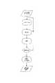
図1は、三次元の動的(すなわち、四次元の)画像データセット8を用いた診察方法全体の一例についてその概要を示すものである。なお、少なくともステップ14、18及び20は、この事例の任意構成である。 FIG. 1 shows an outline of an example of an entire diagnosis method using a three-dimensional dynamic (that is, four-dimensional)
ステップ12では、ユーザは、画像データセット内におけるナビゲート(誘導動作)により、関心構造体が有利に示される断面画像を見つけ出そうとする。任意の構成として、ユーザは、ステップ14において、画像データセットを細分化、すなわち、関心構造体を明瞭に切り出すことができる。次に、ステップ16において、実際の測定が実行されて、例えば、標識の設定、又は断面画像上の距離又は面積の測定が行われる。これら3つのステップは、追加の測定を実行する場合には、必要に応じて繰り返される。次に、ステップ18において、測定結果は、空間と時間の少なくともいずれかにリンク付けされ、ステップ20において表示される。表示においては、画像データセット内で色調を付けて測定結果を強調表示する選択肢が存在する。 In step 12, the user attempts to find a cross-sectional image in which the structure of interest is advantageously shown by navigating in the image data set. As an optional configuration, the user can subdivide the image data set in step 14, i.e., clearly cut out the structure of interest. Next, in step 16, an actual measurement is performed, for example, setting a marker or measuring a distance or area on a cross-sectional image. These three steps are repeated as necessary to perform additional measurements. Next, in step 18, the measurement result is linked to space and / or time and displayed in step 20. In the display, there is an option for highlighting the measurement result with a color tone in the image data set.
次に、ナビゲーション方法におけるステップ12について、図2と図6を参照しながらより詳細に説明する。図2は、三次元超音波測定によってデータ取得/捕捉された三次元画像ボリューム8等を模式的に再現した状態を示している。この例では、患者の身体表面上で超音波トランスデューサを旋回することで、円錐形のデータボリュームから画像データを取得している。この画像ボリュームでのビュー平面のナビゲーションは、ここでは、超音波ヘッドの移動によって模式的に再現されている。したがって、この図には、仮想プローブ2が表示されており、この仮想プローブ2は、仮想サウンド平面1であるビュー平面にしっかりと結合されている。この例では、追加のビュー平面も同時にナビゲートすることができ、例えば、心臓の取り込みにおいて、2つの縦軸断面と1つの短軸断面とを同時にナビゲートすることができる。図2の参照方向3に従って行われる仮想プローブ2の旋回は、基準点4を中心に行われる。この旋回動作は、例えば、約80°に制限されるものであり、この制限により、対話型測定実行中の移動における制約が模式的に再現される。 Next, step 12 in the navigation method will be described in more detail with reference to FIGS. FIG. 2 shows a state in which the three-
図6に示されるように、ビュー平面1に対応する断面画像32が、画面28に表示される。この画面はコンピュータ30に接続されており、そのコンピュータ30には、更に、例えば、コンピュータマウス22の形式の入力装置が接続されている。このマウスは、左側のマウスボタン24、右側のマウスボタン26及びスクロールホイール25を備える。ビュー平面1に対応する断面画像32の他に、画面28は、具体的には、2つの追加の断面画像33,34が表示されている。これらの画像33,34は、仮想プローブ2の入射角度に関して、断面画像32と同一の入射角度に対応したものであるが、ビュー平面1の断面画像32に対して角度α又はβだけ回転されている。このことは、画像データセット8の断面を表示する追加のウィンドウ35に表示されている。つまり、このウィンドウ35では、断面画像32,33,34の位置が破線で示されている。ただし、画面28のこのようなタイプの分割は、単に、好ましい例示にすぎない。 As shown in FIG. 6, a
図2に戻って説明する。仮想プローブ2の基準点4は、仮想記録面5に沿って移動できるのみである。この仮想記録面は、対話型イメージング検査実行中にプローブ又はデータ取得装置のヘッドが存在する面であり、かつ、前記プローブ又は取得装置のヘッドの移動面を模式的に再現したものである。超音波画像検査において、この面は患者の皮膚表面であることが多いが、身体の内側表面、例えば、超音波トランスデューサが気管に挿入された場合は、その気管の表面等であっても、骨の表面であっても、あるいは、取り込む画像のタイプによって規定される身体の外部表面であってもよい。仮想記録面5は、平面であっても、あるいは特定の曲率を持っていてもよく、例えば、走査の対象である目標物を模式的に再現するものであればよい。Returning to FIG. The
プローブ2の縦軸を中心とした回転は、矢印6に従って、例えばマウスのスクロールホイールを用いて実行され、より有利なものでは回転範囲が例えば±90°に制限される。矢印7の方向に対応した、皮膚5の仮想平面に沿った平行移動は、例えば右側のマウスボタンを用いて実現される。 The rotation of the
皮膚の仮想平面5は球面としても実現でき、この場合、球は少なくとも画像ボリューム8を取り囲む状態が好ましい。このように、原理的には任意の断面平面を利用できるが、このことはデータボリュームにおける方向決めを妨げる可能性がある。 The
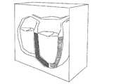
図3に、本方法における任意構成であるステップ16を示す。このステップ16では、関心構造体38、この例では、例えば胎児の頭部を明瞭に切り出す。左側の図は、画像データセットからの断面画像を示すものである。この図では、頭部38は、網掛けして図示されている構造体39、例えば子宮等によって覆われている。これらの構造体を切り取るためには、ユーザは、まず矢印40として表示されているベクトルを断面画像上に固定する。平面43が、ベクトルの始点を通って延在しており、球面42がベクトルの終点を通る状態で延在している。そして、右側の図に示されているように、2つの面43と42の外側に位置する画像データがすべて切り取られる。面42の球面形状を用いたことで、細分化された関心ボリュームは、ほぼ占有的に頭部38のみを含むものとなる。そして、中央の図に従って、頭部の表面ビューをボリュームレンダリングによって生成すると、顔が子宮39の壁面に隠れなくなる。 FIG. 3 shows step 16 which is an optional configuration in the present method. In this step 16, the structure of
このようにして、ユーザが測定を実行したい画像領域を特定し、その領域を明確に切り出すと、その切り出された領域を動的に表示することができる。そして、ここで、動画像データセット内で測定を実行するステップ10について、図4を利用してより詳細に説明する。ここでは、まず、関心フレームFpが、2D又は3Dの画像(フレーム)のタイムシーケンスを基に設定され、あるいは算定される。次に、画像の動的シーケンスが通常の再生速度で表示される。心臓の画像の場合、例えば、1回の拍動の間に取得された20〜30個のフレームが再生される。この例では、通常の再生速度は毎秒20フレームである。 In this way, when the user specifies an image area to be measured and clearly cuts out the area, the cut out area can be dynamically displayed. Here, step 10 of performing measurement in the moving image data set will be described in more detail with reference to FIG. Here, first, the frame of interest Fp is set or calculated based on the time sequence of a 2D or 3D image (frame). The dynamic sequence of images is then displayed at normal playback speed. In the case of a heart image, for example, 20 to 30 frames acquired during one beat are reproduced. In this example, the normal playback speed is 20 frames per second.
そして、関心フレームFpに到達すると、シーケンス動作が停止されて、所定の時間のあいだ、関心フレームが表示される。図4で、このフレームは「延長フレームFp」として示されている。この時間の中でユーザはマーカーLM1とLM2とを設定でき、より長く表示させれば、画像Fp内において、例えばこれらのマーカーにより設定された標識の間の距離を測定できる。表示が中断される時間の長さは、例えば0.5〜5秒、特に好ましくは1〜2秒というような、予め定義された時間であってよい。あるいは、他の実施形態としては、この停止時間は測定が行われている限り存続されるものでもよい。所定の継続時間の後と、測定の完了後の少なくともいずれかにおいて、表示ループの再生が続行される。これにより、ユーザは、シーケンス表示に基づく動的印象と、シーケンスからの静止画像の両方を利用できるようになり、測定の正確な描画を実現できる。このプロセスは、各種の画像平面において1回より多く繰り返すことができる。ポイントを設定した後で、本方法は、その設定されたポイントの調整処理にも利用できる。 When the interest frame Fp is reached, the sequence operation is stopped and the interest frame is displayed for a predetermined time. In FIG. 4, this frame is indicated as “extension frame Fp”. During this time, the user can set the markers LM1 and LM2, and if they are displayed longer, for example, the distance between the labels set by these markers can be measured in the image Fp. The length of time during which the display is interrupted may be a predefined time, for example 0.5-5 seconds, particularly preferably 1-2 seconds. Alternatively, as another embodiment, the stop time may be maintained as long as the measurement is performed. The display loop continues to be played after a predetermined duration and / or after completion of the measurement. As a result, the user can use both the dynamic impression based on the sequence display and the still image from the sequence, and can realize accurate drawing of the measurement. This process can be repeated more than once at various image planes. After setting the points, the method can be used for adjusting the set points.
更に他の実施形態によれば、表示ループは1回より多く実行され、その表示は、毎回異なるフレーム、例えばF1,F2,・・・Fnで停止する。したがって、例えば同一の構造体を移動の各段階で測定することができる。 According to yet another embodiment, the display loop is executed more than once, and the display stops at a different frame each time, eg F1, F2,... Fn. Thus, for example, the same structure can be measured at each stage of movement.
このように、各種の断面平面及び/又は各種の時刻において測定された測定値に基づいて、場所と時刻の両方に測定値をリンクさせることができる。これらのリンクから、追加の読み取り値、例えば、ある測定値の経時変化等を引き出すことができる(ステップ18)。そして、任意構成のステップ20において、これらの測定結果を、表面レンダリングによって取得される二次元のビュー内で、例えば色調を用いて強調表示する。図5に、このようなものの例として、例えば心臓のビューを示す。図において網掛け領域45は、例えば赤色に着色され、点線領域46は明るい青緑色に着色される。このカラーコーディングは、例えば、これに対応して色分けされた心腔壁面の収縮の瞬間に対応する。 Thus, based on measured values measured at various cross-sectional planes and / or at various times, the measured values can be linked to both location and time. From these links, additional readings can be derived, such as changes in certain measurements over time (step 18). Then, in optional step 20, these measurement results are highlighted using, for example, color tone, in a two-dimensional view acquired by surface rendering. FIG. 5 shows, for example, a view of the heart as an example of such a thing. In the figure, the shaded area 45 is colored, for example, red, and the dotted line area 46 is colored light blue-green. This color coding corresponds to the moment of contraction of the heart chamber wall color-coded correspondingly, for example.
図6に、本発明に係る装置の実施形態を模式的に示す。この装置は、画面28、入力装置22、及び、例えばコンピュータであってよい計算ユニット30を含む。また、本発明はコンピュータプログラム製品に組み込むこともでき、このコンピュータプログラム製品はコンピュータ30にインストールされて、そのコンピュータ30に再書込みされた方法を実行させるソフトウェアコード部を含む。 FIG. 6 schematically shows an embodiment of the apparatus according to the present invention. The device includes a
したがって、本発明は、多次元画像データ内での簡単なナビゲーションの方法、構造体を細分化する任意構成のステップ、動的データ上で測定を実行する方法、四次元の測定値をリンクさせるステップ、及び四次元のデータセット内に動的測定結果を表示するステップ20を利用可能にするものである。 Accordingly, the present invention provides a method for simple navigation within multidimensional image data, an arbitrarily structured step for subdividing structures, a method for performing measurements on dynamic data, and a step for linking four-dimensional measurements. And a step 20 of displaying the dynamic measurement results in a four-dimensional data set.
Claims (19)
Translated fromJapanese多次元画像データセット(8)内でのナビゲーションステップ(12)を含むものであり、当該ステップでは、ユーザは入力装置(22)を利用して画像データセット(8)内でビュー平面(1)を移動させることができ、その間、当該ビュー平面に対応する断面画像(32)が表示されるようになっており、
前記ビュー平面(1)は、対話型イメージング検査実行中のビュー角度に対応する角度で、前記ビュー平面(1)の移動の自由度を制限する態様で前記画像データセット(8)と交差し、ユーザが慣れている移動を再現するために、前記ビュー平面(1)の移動の自由度(3,6,7)は、対話型イメージング検査実行中のプローブ(2)の移動の自由度に対応していることを特徴とする方法。A method for navigation and measurement in a multi-dimensional image data set (8) of a target acquired by a medical imaging method , comprising:
It includes a navigation step (12) in the multi-dimensional image data set (8), in which the user uses the input device (22) to view the view plane (1) in the image data set (8). In the meantime, a cross-sectional image (32) corresponding to the view plane is displayed,
The view plane (1) intersects the image data set (8) ina manner that limits the freedom of movement of the view plane (1) at an angle corresponding to the view angle during the execution of an interactive imaging examination.In order to reproduce the movement that the user is accustomed to, the degree of freedom (3, 6, 7) of the view plane (1) corresponds to the degree of freedom of movement of the probe (2) during the interactive imaging examination. A method characterized by that.
前記ベクトル(40)の終点及び/又は始点を通り、且つ前記ベクトルに対して垂直に伸びる真直平面(43)、湾曲平面(42)又は自由形状曲面が、前記画像データセット内に設定される工程と、
前記平面(43,42)で区切られた領域の片側にある画像データが消去される工程とを有するものであることを特徴とする目標物の多次元画像データセット内におけるナビゲーション及び測定の方法。7. The method according to any one of claims 1 to 6, comprising an additional step (14) of unambiguously cutting out a structure of interest (38) in the target. Setting a vector (40) to be pointed over the structure of interest (38) on the cross-sectional image;
A straight plane (43), a curved plane (42) or a free-form curved surface that passes through the end point and / or start point of the vector (40) and extends perpendicular to the vector is set in the image data set. When,
A method for navigation and measurement of a target in a multi-dimensional image data set, the method further comprising: erasing image data on one side of an area partitioned by the plane (43, 42).
目標物について複数の連続した二次元又は三次元のフレーム(F1,F2,・・・Fn)のシーケンスを含む多次元動画像データセット(8)内で測定及び/又は標識設定を行うステップ(16)を含み、当該ステップは、
測定を実行しようとする関心フレーム(Fp)の選択と、
前記個々のフレームの連続表示による前記シーケンス再生の実行とを有するものであり、当該再生では、前記関心フレーム(Fp)の表示のときに、予め定義された時間のあいだ連続表示動作が停止され、その間に、ユーザは関心フレーム上で、測定及び/又は標識(LM1,LM2)の設定を行うことできることを特徴とする目標物の多次元画像データセット内におけるナビゲーション及び測定の方法。A method according to any one of claims 1 to 7, comprising
Measuring and / or labeling in a multi-dimensional video data set (8) comprising a sequence of a plurality of consecutive two-dimensional or three-dimensional frames (F1, F2,... Fn) for a target (16 )
Selecting a frame of interest (Fp) to perform the measurement;
Execution of the sequence reproduction by continuous display of the individual frames. In the reproduction, the continuous display operation is stopped for a predetermined time when the frame of interest (Fp) is displayed, In the meantime, a method for navigation and measurement in a multi-dimensional image data set of a target, characterized in that the user can perform measurement and / or setting of signs (LM1, LM2) on the frame of interest.
ビュー平面(1)のナビゲーション手段であり、ユーザが前記画像データセット(8)内で移動させるときに用いられる入力装置(22)と、
前記画像データセットから前記ビュー平面(1)に対応する断面画像(32)を生成する演算手段(30)と、
前記断面画像(32)を表示する画面(28)とを含み、
前記ビュー平面(1)は、対話型イメージング検査実行中のビュー角度に対応する角度で、前記ビュー平面(1)の移動の自由度を制限する態様で、前記画像データセット(8)と交差しているものであり、ユーザが慣れている移動を再現するために、前記ビュー平面(1)の移動の自由度(3,6,7)は、対話型イメージング検査実行中のプローブ(2)の移動の自由度に対応していることとを特徴とする装置。An apparatus for performing navigation and measurement in a multi-dimensional image data set (8) of a target acquired by a medical imaging method,
An input device (22) which is a navigation means of the view plane (1) and is used when a user moves in the image data set (8);
Computing means (30) for generating a cross-sectional image (32) corresponding to the view plane (1) from the image data set;
A screen (28) for displaying the cross-sectional image (32),
The view plane (1) intersects the image data set (8) ina manner that limits the degree of freedom of movement of the view plane (1) at an angle corresponding to the view angle during an interactive imaging examination. Inorder to reproduce the movement that theuser is accustomed to, the degree of freedom (3, 6, 7) of the view plane (1) A device characterized by corresponding to the degree of freedom of movement.
断面画像上に、関心構造体(38)にさしわたすように表示されるベクトル(40)を設定することができ、
前記ベクトル(40)の終点及び/又は始点を通り、前記ベクトル(40)に対して垂直に伸びる真直平面(43)、湾曲平面(42)又は自由形状曲面を、前記画像データセット内に設定することができ、
前記平面の片側に位置する画像データが消去されて、前記目標物内の前記関心構造体(38)を明瞭に切り出すことができることを特徴とする目標物の多次元画像データセット(8)内におけるナビゲーション及び測定を行う装置。The apparatus according to any one of claims 14 to 16, comprising:
On the cross-sectional image, a vector (40) displayed so as to touch the structure of interest (38) can be set,
A straight plane (43), curved plane (42), or free-form curved surface that passes through the end point and / or start point of the vector (40) and extends perpendicularly to the vector (40) is set in the image data set. It is possible,
In the multi-dimensional image data set (8) of the target object, the image data located on one side of the plane is erased and the structure of interest (38) in the target object can be clearly cut out. A device for navigation and measurement.
ユーザがフレーム(Fp)内にマーカー(LM1,LM2)を設定したり、測定を実行したりするために利用できる入力装置(22)と、
前記フレームそれぞれの連続表示により前記シーケンス再生を実行するための画面(28)とを含むものであり、
測定が行われる関心フレーム(Fp)の選択が可能であると共に前記連続表示動作が前記関心フレーム(Fp)において予め定義された時間のあいだ停止し、その間に、ユーザは、マーカー(LM1,LM2)を設定したり、あるいは測定を実行したりすることができることを特徴とする目標物の多次元画像データセット(8)内におけるナビゲーション及び測定を行う装置。The apparatus according to any one of claims 14 to 17, wherein the image data set includes a plurality of two-dimensional or three-dimensional frames (F1, F2,. ), And the apparatus comprises:
An input device (22) that can be used by the user to set markers (LM1, LM2) in the frame (Fp) and to perform measurements;
A screen (28) for executing the sequence reproduction by continuous display of each of the frames,
The frame of interest (Fp) on which the measurement is to be made can be selected and the continuous display operation stops for a predefined time in the frame of interest (Fp), during which time the user can select the marker (LM1, LM2) A device for performing navigation and measurement in a multi-dimensional image data set (8) of a target, characterized in that it can be set or measurement can be performed.
Applications Claiming Priority (3)
| Application Number | Priority Date | Filing Date | Title |
|---|---|---|---|
| DE102005041581.4 | 2005-09-01 | ||
| DE102005041581ADE102005041581A1 (en) | 2005-09-01 | 2005-09-01 | Method and device for navigation and measurement in a multi-dimensional image data set |
| PCT/EP2006/007061WO2007025608A1 (en) | 2005-09-01 | 2006-07-18 | Method and device for navigating and measuring in a multidimensional image data set |
Publications (2)
| Publication Number | Publication Date |
|---|---|
| JP2009506808A JP2009506808A (en) | 2009-02-19 |
| JP4875791B2true JP4875791B2 (en) | 2012-02-15 |
Family
ID=37071718
Family Applications (1)
| Application Number | Title | Priority Date | Filing Date |
|---|---|---|---|
| JP2008528361AActiveJP4875791B2 (en) | 2005-09-01 | 2006-07-18 | Method and apparatus for navigation and measurement in a multidimensional image data set |
Country Status (6)
| Country | Link |
|---|---|
| US (1) | US8155407B2 (en) |
| EP (1) | EP1920422B1 (en) |
| JP (1) | JP4875791B2 (en) |
| AT (1) | ATE498171T1 (en) |
| DE (2) | DE102005041581A1 (en) |
| WO (1) | WO2007025608A1 (en) |
Families Citing this family (7)
| Publication number | Priority date | Publication date | Assignee | Title |
|---|---|---|---|---|
| US8494250B2 (en)* | 2008-06-06 | 2013-07-23 | Siemens Medical Solutions Usa, Inc. | Animation for conveying spatial relationships in three-dimensional medical imaging |
| DE102008055132A1 (en) | 2008-12-23 | 2010-07-01 | Tomtec Imaging Systems Gmbh | Method and device for navigating in a multi-dimensional image data record |
| CN102356408A (en)* | 2009-03-20 | 2012-02-15 | 皇家飞利浦电子股份有限公司 | Visualization of the scene view |
| JP5950619B2 (en)* | 2011-04-06 | 2016-07-13 | キヤノン株式会社 | Information processing device |
| KR101487688B1 (en)* | 2012-11-23 | 2015-01-29 | 삼성메디슨 주식회사 | Ultrasound system and method of providing navigator for guiding position of plane |
| DE102014206328A1 (en)* | 2014-04-02 | 2015-10-08 | Andreas Brückmann | Method for imitating a real guide of a diagnostic examination device, arrangement and program code therefor |
| CN112545565B (en)* | 2020-11-30 | 2023-02-21 | 深圳开立生物医疗科技股份有限公司 | Intravascular ultrasound image construction method and device, ultrasound equipment and storage medium |
Citations (9)
| Publication number | Priority date | Publication date | Assignee | Title |
|---|---|---|---|---|
| JPH0360648A (en)* | 1989-07-28 | 1991-03-15 | Hitachi Medical Corp | Ct device |
| JPH07222742A (en)* | 1994-02-09 | 1995-08-22 | Aloka Co Ltd | Ultrasonic diagnostic system |
| JPH0984786A (en)* | 1995-09-25 | 1997-03-31 | Ge Yokogawa Medical Syst Ltd | Operating method of ultrasonic diagnostic device, and ultrasonic diagnostic device |
| JPH1085210A (en)* | 1996-09-12 | 1998-04-07 | Aloka Co Ltd | Ultrasonic diagnostic device |
| JP2001128975A (en)* | 1999-08-20 | 2001-05-15 | Toshiba Corp | Ultrasound diagnostic equipment |
| JP2001145631A (en)* | 1999-11-22 | 2001-05-29 | Aloka Co Ltd | Ultrasonic diagnostic device |
| JP2002330968A (en)* | 2001-03-05 | 2002-11-19 | Matsushita Electric Ind Co Ltd | Ultrasound diagnostic device and image processing device |
| JP2004141612A (en)* | 2002-08-30 | 2004-05-20 | Hitachi Medical Corp | Method and apparatus for image processing |
| WO2004098414A1 (en)* | 2003-05-08 | 2004-11-18 | Hitachi Medical Corporation | Reference image display method for ultrasonography and ultrasonograph |
Family Cites Families (7)
| Publication number | Priority date | Publication date | Assignee | Title |
|---|---|---|---|---|
| JPH07114652A (en)* | 1993-10-18 | 1995-05-02 | Hitachi Medical Corp | Device and method for moving picture display for three-dimensional image |
| US5609485A (en)* | 1994-10-03 | 1997-03-11 | Medsim, Ltd. | Medical reproduction system |
| US6524246B1 (en)* | 2000-10-13 | 2003-02-25 | Sonocine, Inc. | Ultrasonic cellular tissue screening tool |
| US7123766B2 (en)* | 2002-02-11 | 2006-10-17 | Cedara Software Corp. | Method and system for recognizing and selecting a region of interest in an image |
| DE10222655A1 (en) | 2002-05-22 | 2003-12-18 | Dino Carl Novak | Training system, especially for teaching use of a medical ultrasonic system, whereby a computer program is used to output medical sectional image data corresponding to the position of a control probe on a human body model |
| DE10258952A1 (en)* | 2002-12-16 | 2004-08-19 | Novak, Dino Carl, Dr. | Input device, especially for training operators in the use of medical ultrasonic imaging technology, whereby a mouse-type device is used that is moved over a surface and its position reproduced on a computer monitor |
| KR100697728B1 (en)* | 2004-10-22 | 2007-03-21 | 주식회사 메디슨 | Apparatus and method for improving image quality of ultrasonic cross-sectional images |
- 2005
- 2005-09-01DEDE102005041581Apatent/DE102005041581A1/ennot_activeWithdrawn
- 2006
- 2006-07-18EPEP06776289Apatent/EP1920422B1/enactiveActive
- 2006-07-18DEDE502006008885Tpatent/DE502006008885D1/enactiveActive
- 2006-07-18ATAT06776289Tpatent/ATE498171T1/enactive
- 2006-07-18USUS12/064,710patent/US8155407B2/enactiveActive
- 2006-07-18JPJP2008528361Apatent/JP4875791B2/enactiveActive
- 2006-07-18WOPCT/EP2006/007061patent/WO2007025608A1/enactiveApplication Filing
Patent Citations (9)
| Publication number | Priority date | Publication date | Assignee | Title |
|---|---|---|---|---|
| JPH0360648A (en)* | 1989-07-28 | 1991-03-15 | Hitachi Medical Corp | Ct device |
| JPH07222742A (en)* | 1994-02-09 | 1995-08-22 | Aloka Co Ltd | Ultrasonic diagnostic system |
| JPH0984786A (en)* | 1995-09-25 | 1997-03-31 | Ge Yokogawa Medical Syst Ltd | Operating method of ultrasonic diagnostic device, and ultrasonic diagnostic device |
| JPH1085210A (en)* | 1996-09-12 | 1998-04-07 | Aloka Co Ltd | Ultrasonic diagnostic device |
| JP2001128975A (en)* | 1999-08-20 | 2001-05-15 | Toshiba Corp | Ultrasound diagnostic equipment |
| JP2001145631A (en)* | 1999-11-22 | 2001-05-29 | Aloka Co Ltd | Ultrasonic diagnostic device |
| JP2002330968A (en)* | 2001-03-05 | 2002-11-19 | Matsushita Electric Ind Co Ltd | Ultrasound diagnostic device and image processing device |
| JP2004141612A (en)* | 2002-08-30 | 2004-05-20 | Hitachi Medical Corp | Method and apparatus for image processing |
| WO2004098414A1 (en)* | 2003-05-08 | 2004-11-18 | Hitachi Medical Corporation | Reference image display method for ultrasonography and ultrasonograph |
Also Published As
| Publication number | Publication date |
|---|---|
| EP1920422A1 (en) | 2008-05-14 |
| ATE498171T1 (en) | 2011-02-15 |
| EP1920422B1 (en) | 2011-02-09 |
| WO2007025608A1 (en) | 2007-03-08 |
| DE102005041581A1 (en) | 2007-03-15 |
| US20080240534A1 (en) | 2008-10-02 |
| US8155407B2 (en) | 2012-04-10 |
| DE502006008885D1 (en) | 2011-03-24 |
| JP2009506808A (en) | 2009-02-19 |
Similar Documents
| Publication | Publication Date | Title |
|---|---|---|
| EP3003161B1 (en) | Method for 3d acquisition of ultrasound images | |
| US6049622A (en) | Graphic navigational guides for accurate image orientation and navigation | |
| JP5963736B2 (en) | Video to convey spatial relationships in 3D medical images | |
| CN101467894B (en) | Flashlight view of anatomical structure | |
| JP4676021B2 (en) | Diagnosis support apparatus, diagnosis support program, and diagnosis support method | |
| JP4875791B2 (en) | Method and apparatus for navigation and measurement in a multidimensional image data set | |
| JP2020522827A (en) | Use of augmented reality in surgical navigation | |
| RU2419882C2 (en) | Method of visualising sectional planes for arched oblong structures | |
| JP2000500679A (en) | 3D image forming system | |
| CN109313698A (en) | Synchronous surface and internal tumours detection | |
| JP7216131B2 (en) | Method, computer program product and ultrasound system for visualizing a sequence of ultrasound images | |
| CN101849843A (en) | Three-dimensional echocardiography virtual endoscopic navigation method | |
| Boctor et al. | PC-based system for calibration, reconstruction, processing, and visualization of 3D ultrasound data based on a magnetic-field position and orientation sensing system | |
| Krapichler et al. | VR interaction techniques for medical imaging applications | |
| JP2008515520A (en) | Method and system for maintaining a consistent anatomical view of displayed image data | |
| JP2021531122A (en) | Ultrasound Systems and Methods for Induced Shear Wave Elastography of Anisotropic Tissues | |
| JP7504942B2 (en) | Representation device for displaying a graphical representation of an augmented reality - Patent Application 20070123633 | |
| JP2022090787A (en) | Ultrasonic diagnostic system and operation support method | |
| JP4786307B2 (en) | Image processing device | |
| JP4936281B2 (en) | Ultrasonic diagnostic equipment | |
| EP3843637B1 (en) | Ultrasound system and methods for smart shear wave elastography | |
| JP7172086B2 (en) | Surgery simulation device and surgery simulation program | |
| Krapichler et al. | Human-machine interface for a VR-based medical imaging environment | |
| JPH10132516A5 (en) | ||
| JP2005270351A (en) | Method and device for ultrasonic three-dimensional imaging |
Legal Events
| Date | Code | Title | Description |
|---|---|---|---|
| A529 | Written submission of copy of amendment under article 34 pct | Free format text:JAPANESE INTERMEDIATE CODE: A529 Effective date:20080422 | |
| A621 | Written request for application examination | Free format text:JAPANESE INTERMEDIATE CODE: A621 Effective date:20080508 | |
| A977 | Report on retrieval | Free format text:JAPANESE INTERMEDIATE CODE: A971007 Effective date:20110124 | |
| A131 | Notification of reasons for refusal | Free format text:JAPANESE INTERMEDIATE CODE: A131 Effective date:20110222 | |
| A601 | Written request for extension of time | Free format text:JAPANESE INTERMEDIATE CODE: A601 Effective date:20110511 | |
| A602 | Written permission of extension of time | Free format text:JAPANESE INTERMEDIATE CODE: A602 Effective date:20110518 | |
| A601 | Written request for extension of time | Free format text:JAPANESE INTERMEDIATE CODE: A601 Effective date:20110621 | |
| A602 | Written permission of extension of time | Free format text:JAPANESE INTERMEDIATE CODE: A602 Effective date:20110628 | |
| A521 | Request for written amendment filed | Free format text:JAPANESE INTERMEDIATE CODE: A523 Effective date:20110715 | |
| A521 | Request for written amendment filed | Free format text:JAPANESE INTERMEDIATE CODE: A523 Effective date:20110819 | |
| TRDD | Decision of grant or rejection written | ||
| A01 | Written decision to grant a patent or to grant a registration (utility model) | Free format text:JAPANESE INTERMEDIATE CODE: A01 Effective date:20111115 | |
| A01 | Written decision to grant a patent or to grant a registration (utility model) | Free format text:JAPANESE INTERMEDIATE CODE: A01 | |
| A61 | First payment of annual fees (during grant procedure) | Free format text:JAPANESE INTERMEDIATE CODE: A61 Effective date:20111126 | |
| FPAY | Renewal fee payment (event date is renewal date of database) | Free format text:PAYMENT UNTIL: 20141202 Year of fee payment:3 | |
| R150 | Certificate of patent or registration of utility model | Ref document number:4875791 Country of ref document:JP Free format text:JAPANESE INTERMEDIATE CODE: R150 Free format text:JAPANESE INTERMEDIATE CODE: R150 | |
| R250 | Receipt of annual fees | Free format text:JAPANESE INTERMEDIATE CODE: R250 | |
| R250 | Receipt of annual fees | Free format text:JAPANESE INTERMEDIATE CODE: R250 | |
| R250 | Receipt of annual fees | Free format text:JAPANESE INTERMEDIATE CODE: R250 | |
| R250 | Receipt of annual fees | Free format text:JAPANESE INTERMEDIATE CODE: R250 | |
| R250 | Receipt of annual fees | Free format text:JAPANESE INTERMEDIATE CODE: R250 | |
| R250 | Receipt of annual fees | Free format text:JAPANESE INTERMEDIATE CODE: R250 | |
| R250 | Receipt of annual fees | Free format text:JAPANESE INTERMEDIATE CODE: R250 | |
| R250 | Receipt of annual fees | Free format text:JAPANESE INTERMEDIATE CODE: R250 | |
| R250 | Receipt of annual fees | Free format text:JAPANESE INTERMEDIATE CODE: R250 | |
| R250 | Receipt of annual fees | Free format text:JAPANESE INTERMEDIATE CODE: R250 | |
| R250 | Receipt of annual fees | Free format text:JAPANESE INTERMEDIATE CODE: R250 |