JP4875117B2 - Image processing device - Google Patents
Image processing deviceDownload PDFInfo
- Publication number
- JP4875117B2 JP4875117B2JP2009062044AJP2009062044AJP4875117B2JP 4875117 B2JP4875117 B2JP 4875117B2JP 2009062044 AJP2009062044 AJP 2009062044AJP 2009062044 AJP2009062044 AJP 2009062044AJP 4875117 B2JP4875117 B2JP 4875117B2
- Authority
- JP
- Japan
- Prior art keywords
- image
- recognition
- unit
- character
- business card
- Prior art date
- Legal status (The legal status is an assumption and is not a legal conclusion. Google has not performed a legal analysis and makes no representation as to the accuracy of the status listed.)
- Expired - Fee Related
Links
Images


Classifications
- G—PHYSICS
- G06—COMPUTING OR CALCULATING; COUNTING
- G06V—IMAGE OR VIDEO RECOGNITION OR UNDERSTANDING
- G06V30/00—Character recognition; Recognising digital ink; Document-oriented image-based pattern recognition
- G06V30/40—Document-oriented image-based pattern recognition
- G06V30/41—Analysis of document content
- G06V30/414—Extracting the geometrical structure, e.g. layout tree; Block segmentation, e.g. bounding boxes for graphics or text
- G—PHYSICS
- G06—COMPUTING OR CALCULATING; COUNTING
- G06V—IMAGE OR VIDEO RECOGNITION OR UNDERSTANDING
- G06V10/00—Arrangements for image or video recognition or understanding
- G06V10/20—Image preprocessing
- G06V10/24—Aligning, centring, orientation detection or correction of the image
- G06V10/245—Aligning, centring, orientation detection or correction of the image by locating a pattern; Special marks for positioning
- G—PHYSICS
- G06—COMPUTING OR CALCULATING; COUNTING
- G06V—IMAGE OR VIDEO RECOGNITION OR UNDERSTANDING
- G06V30/00—Character recognition; Recognising digital ink; Document-oriented image-based pattern recognition
- G06V30/10—Character recognition
Landscapes
- Engineering & Computer Science (AREA)
- Physics & Mathematics (AREA)
- Computer Vision & Pattern Recognition (AREA)
- General Physics & Mathematics (AREA)
- Multimedia (AREA)
- Theoretical Computer Science (AREA)
- Computer Graphics (AREA)
- Geometry (AREA)
- Artificial Intelligence (AREA)
- Studio Devices (AREA)
- Character Discrimination (AREA)
Description
Translated fromJapanese本発明は、カメラで撮影した画像を処理する画像処理装置に関する。 The present invention relates to an image processing apparatus that processes an image captured by a camera.
最近では、携帯端末やPCなどの情報機器に高解像度のカメラが内蔵されるようになり、このようなカメラを使い人物の顔を認識したり、またバーコードやQRコードに代表されるコードパターンを認識したり、名刺内容などの文字を認識するなど、さまざまな認識処理を携帯端末やPCで行うことが可能となっている。 Recently, high-resolution cameras have been built into information devices such as portable terminals and PCs, and human faces can be recognized using such cameras, and code patterns represented by barcodes and QR codes can be used. Various recognition processes such as recognizing characters and characters such as business card contents can be performed on a portable terminal or a PC.
このようにカメラで撮影した画像を携帯端末やPC等の情報機器で認識処理を行う場合、カメラまたは認識対象物(被写体)のどちらかは手持ちである場合が多く、手ぶれが発生したり、フォーカスが合わない画像が入力されてしまったりすることがある。手ぶれやフォーカスが合わない画像を認識処理した場合、認識性能が低下するという問題があった。 In this way, when an image captured by a camera is recognized by an information device such as a portable terminal or a PC, either the camera or the recognition target (subject) is often held by hand, causing camera shake or focusing. Images that do not match may be entered. When an image that is out of focus or in-focus is recognized, there is a problem that the recognition performance deteriorates.
そこで、近年では、カメラから連続的に入力される画像に対してフォーカス状態の検出を行い、認識対象物(被写体)にフォーカスが合った状態がユーザに分かるようにする、あるいはフォーカスが合うとシステムが自動的に撮影を行うことにより、手ぶれやフォーカスずれのない静止画を撮影するシステムが考えられている(例えば特許文献1参照) Therefore, in recent years, the focus state is detected for images continuously input from the camera so that the user can know the state in which the recognition object (subject) is in focus or the system is in focus. A system for taking a still image free of camera shake and focus deviation by automatically taking a picture is considered (for example, see Patent Document 1).
しかしながら、上記した技術の場合、ある程度、広い領域を撮影対象とする際に、画像内の一部はフォーカスが合っていても他の部分のフォーカスが合っていないことも多いため、認識対象物(被写体)全体のフォーカスが合った画像が撮影できない、あるいは撮影が完了するまでに長い時間やユーザの試行錯誤を要するといった問題があった。 However, in the case of the above-described technique, when a large area is captured to some extent, there are many cases where a part of the image is in focus but the other part is not in focus. (Subject) There is a problem that an image in which the entire focus is incapable of being photographed, or a long time and a trial and error of the user are required until the photographing is completed.
また、カメラで画像を撮影する場合、レンズ特性などの原因で、画像の中心部の画質はよいが、周辺部ではぼやけたり、ゆがんだり、または輝度が暗くなるなど、画像の画質が部分的に劣化している場合がある。 Also, when taking an image with a camera, the image quality at the center of the image is good due to lens characteristics, etc., but the image quality of the image is partially, such as blurred, distorted, or darkened at the periphery. May have deteriorated.
さらに、画像を認識する場合は、被写体である認識対象物をなるべく大きい状態で撮影範囲の中心に入れるように撮影することが必要であるが、認識対象物が中心になるとは限らず、特に撮影範囲の中心から離れた画像領域(周辺部)を認識する場合、その部分では認識性能が低下するという問題があった。 Furthermore, when recognizing an image, it is necessary to shoot so that the recognition target object, which is a subject, is placed in the center of the shooting range as much as possible. However, the recognition target is not always at the center. When recognizing an image region (peripheral portion) that is distant from the center of the range, there is a problem that the recognition performance deteriorates in that portion.
本発明はこのような課題を解決するためになされたもので、認識対象物(被写体)やカメラがぶれやすい状態で撮影される画像から所望の情報を高精度に認識することができる画像処理装置を提供することを目的とする。 The present invention has been made to solve such a problem, and is an image processing apparatus capable of accurately recognizing desired information from a recognition target object (subject) or an image photographed in a state in which the camera is likely to shake. The purpose is to provide.
上記の課題を解決するために、本発明の画像処理装置は、カメラで認識対象物が撮影された画像を記憶可能なメモリと、前記画像を前記メモリに記録する画像入力部と、前記画像内に存在する前記認識対象物が認識可能な状態か否かを、予め設定された判定条件に従って判定する認識対象状態判定部と、前記認識対象状態判定部により認識可能な状態と判定された前記認識対象物の画像領域を検出する認識対象検出部と、前記メモリに記憶された複数の画像から前記認識対象物の移動量を検出する移動量検出部と、前記メモリから読み出した前記認識対象物の画像領域から、前記移動量検出部により検出された前記認識対象物の移動量に従って画像領域間の位置の対応をとり、前記画像領域内の認識すべき少なくとも一つの部分領域を検出する部分領域検出部と、前記部分領域検出部により検出された個々の部分領域に対して認識処理を行い、認識された文字および/またはパターンとその信頼度を前記部分領域毎の認識結果として前記メモリに記憶する認識部と、撮影時刻の異なる画像領域を認識して得られた同じ部分領域の文字認識結果を前記メモリから読み出し、部分領域毎に時系列として得られる文字認識結果から、部分領域に含まれる文字毎に最も出現割合の高い文字をそれぞれ決定し、それらを連結した文字列を認識結果として出力する認識結果統合部とを具備することを特徴とする。In order to solve the above problems, an image processing apparatus according to the present invention includes a memory capable of storing an image obtained by photographing a recognition object with a camera, an image input unit that records the image in the memory, The recognition target state determination unit that determines whether or not the recognition target object existing in the state is recognizable according to a predetermined determination condition, and the recognition that is determined to be recognizable by the recognition target state determination unit A recognition target detection unit for detecting an image area of the target object, a movement amount detection unit for detecting a movement amount of the recognition target object from a plurality of images stored in the memory, and the recognition target object read from the memory the image areatakes a corresponding position between the image area according to the movement amount of the recognition target object detected by the moving amount detecting unit, detecting the at least one partial area to be recognized in the image area A recognition process is performed on each partial area detected by the partial area detection unit and the partial area detection unit, and the recognized character and / or pattern and its reliability are recognized as the recognition result for each partial area. The character recognition result of the same partial area obtained by recognizing the image area having a different shooting time from the recognition unit stored in the memory is read from the memory, and the partial area is obtained from the character recognition result obtained as a time series for each partial area. And a recognition result integration unit thatdetermines a character having the highest appearance rate for each included character and outputsa character string obtained by connecting the characters as a recognition result.
本発明によれば、認識対象物(被写体)やカメラがぶれやすい状態で撮影される画像から所望の情報を高精度に認識することができる。 ADVANTAGE OF THE INVENTION According to this invention, desired information can be recognized with high precision from the image image | photographed in the state which is easy to shake the recognition target object (object) and the camera.
以下、図面を参照して、本発明の一つの実施の形態の画像処理装置を詳細に説明する。 Hereinafter, an image processing apparatus according to an embodiment of the present invention will be described in detail with reference to the drawings.
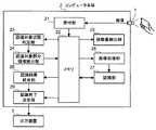
この実施形態の画像処理装置は、図1に示すように、カメラ搭載型のノートPCなどであり、機能的には、例えばCCDカメラなどの入力装置(以下これをカメラ1という)と、コンピュータ本体2と、例えば液晶表示装置などの出力装置3とを備えている。The image processing apparatus of this embodiment, as shown in FIG. 1, and the like cameras mounted typenotes PC, functionally, for example, an input device such as a CCD camera (hereinafter this is called camera 1), the computer A main body 2 and an
この他、画像処理装置としては、例えば(Universal Serial Bus:USB)接続タイプの外付けWEBカメラなどをUSBコードなどで接続したデスクトップ型のコンピュータやカメラ付携帯電話機などであってもよい。 In addition, the image processing apparatus may be, for example, a desktop computer or a mobile phone with a camera in which a (Universal Serial Bus: USB) connection type external WEB camera or the like is connected by a USB cord or the like.
カメラ1は、例えば手などで両端を掴んでレンズの視野(撮影範囲)内にかざした被写体(名刺、葉書、写真などの矩形の帳票などの認識対象物)を撮影しデジタル画像としてコンピュータ本体2に入力する撮像手段である。 The camera 1, for example, grabs both ends with a hand or the like and shoots a subject (a recognition object such as a business card, a postcard, a rectangular form such as a photograph) held in the field of view (shooting range) of the lens, and the computer body 2 as a digital image. It is an imaging means to input to.
この実施形態では、入力装置として、カメラ1自体を例示したが、「カメラ1により撮影された画像」をコンピュータ本体2に入力するものであれば、ネットワーク上のサーバやネットワーク回線、その通信インターフェースなども含まれる。この他、入力装置1としては、様々なものを許容する。 In this embodiment, the camera 1 itself is exemplified as the input device. However, as long as the “image captured by the camera 1” is input to the computer main body 2, a server on the network, a network line, a communication interface thereof, and the like. Is also included. In addition, various types of input device 1 are allowed.
出力装置3は、コンピュータ本体2で画像認識処理された結果を画面に表示(出力)する。この他、カメラ1によって撮影された画像や認識結果を出力できるものであれば、液晶表示装置以外のものであってもよい。 The
以下の説明では、認識対象物として、名刺を一例にあげ、カメラ1で撮影された名刺の画像や認識結果を出力装置3の画面に表示する例について説明する。 In the following description, a business card is taken as an example of a recognition target, and an example of displaying a business card image taken by the camera 1 and a recognition result on the screen of the
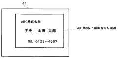
出力装置3は、図4に示すようなプレビュー画面41を備えている。プレビュー画面41には、カメラ1で撮影された名刺画像43が連続して表示される。また、このプレビュー画面41には、ユーザが名刺の位置合わせを適切に行えるように、名刺の外縁部の位置合わせ用のガイドライン(名刺枠)42が表示される。 The
ユーザはプレビュー画面41に表示された名刺枠42内に、撮影およびプレビューされる名刺画像43が収まるように、手に持った名刺をカメラ1のレンズの視野方向(撮影範囲内)にかざすものとする。名刺枠42内に名刺画像43が収まるのであれば、名刺を固定してカメラ1の側を移動してもよい。 The user holds the business card held in his / her hand in the viewing direction of the lens of the camera 1 (within the photographing range) so that the
ユーザが、プレビュー画面41内における名刺画像43の位置を直感的に合わせやすいように、例えば手に持った名刺を右に動かすと、プレビュー画面41に映る名刺画像43(プレビュー画像という)も右に移動するように、カメラ1からコンピュータ本体2に入力された画像をそのまま画面に表示するのではなく、図5に示すように、名刺を裏返して透かした状態の画像44(これを鏡像44という)を表示するようにしてもよい。 For example, when the user moves a business card held in his hand to the right so that the position of the
図2に示すように、コンピュータ本体2は、受付部21、メモリ22、認識対象状態判定部23、認識対象部分領域検出部24、移動量検出部25、画像処理部26、認識部27、認識結果統合部28、認識終了決定部29などを備えている。メモリ22以外の要素は、ハードディスク装置にインストールされたプログラムにより実現される。なお上記各要素はソフトウェアに限らずハードウェアで実現してもよい。 As shown in FIG. 2, the computer main body 2 includes a
受付部21は、カメラ1から入力される画像をメモリ22の異なるバッファ領域に順次記憶する画像入力部として機能する。メモリ22に記憶される画像には、撮影時刻(受付時刻)が付与される。また受付部21は、処理対象の画像をメモリ22から順に読み出して画像パターンを認識するのに適した形式に変換する入力画像処理手段として機能する。 The receiving
なお、画像のファイルタイプが予め定めた形式に適さない場合や画像全体が歪んでいた場合など、そのままでは認識に不都合が生じる。この場合、受付部21は、適したファイルタイプへの変換や理想的なカメラレンズと実際のレンズとの画像の差から得た補正用パラメータの使用による歪み補正などの既知の画像処理技術を用いて画像を修正する。 In addition, when the file type of the image is not suitable for a predetermined format or when the entire image is distorted, the recognition is inconvenient. In this case, the
カメラ1により撮影された画像(以下これを撮影画像という)がコンピュータ本体2に入力されると、その撮影画像は受付部21により受け付けられてメモリ22にバッファリングされる。メモリ22には、画像が記憶される他、予め認識終了条件、処理条件、判定条件などが設定されている。 When an image captured by the camera 1 (hereinafter referred to as a captured image) is input to the computer main body 2, the captured image is received by the receiving
認識対象状態判定部23は、メモリ22に記憶された撮影画像を読み出して、撮影画像内の名刺が認識可能な状態か否かを、予め設定された判定条件に従って判定する。
この例のように認識対象物が名刺である場合、判定条件としては、図4に示すガイド枠42付近に名刺画像43の縁が検出できているか否か、および/または名刺の部分にフォーカスがある程度合っているか否かが判定される。ガイド枠42付近に名刺画像43の縁が存在しているか、またはフォーカスがある程度合っていれば、名刺が認識可能な状態と判定される。また撮影された名刺の大きさが撮影範囲よりも広い場合や、ガイド枠42内付近に名刺画像43の縁が存在していない場合には、名刺が認識不可能な状態と判定される。The recognition target
When the recognition target is a business card as in this example, the determination condition is whether or not the edge of the
認識対象状態判定部23は、撮影画像内の名刺が認識不可能な状態であると判定した場合、予めメモリ22に設定されている処理条件に従って次の処理を行う。
処理条件として、例えば「名刺が認識不可能な状態は次の撮影画像を判定する」と設定されていた場合、次の撮影画像をメモリ22から読み出して撮影画像の状態を判定する。また「名刺が認識不可能な状態は画像の高画質化処理を行い再判定する」と設定されていた場合、画像処理部26に対して画像の品質向上のための高画質化処理を行わせる。そして高画質化処理された当該撮影画像またはその一部の名刺画像の部分をメモリ22から読み出して名刺が認識可能な状態か否かを再判定する。When the recognition target
For example, if the processing condition is set to “determine the next captured image when the business card cannot be recognized”, the next captured image is read from the
認識対象状態判定部23は、名刺が認識不可能な状態と判定した場合、カメラ1の撮影範囲内で名刺が認識可能となるよう移動を促す情報を出力装置3へ出力する。移動を促す情報としては、例えば移動方向を指示する文字や図形などの表示メッセージ、音声メッセージ等である。 When the recognition target
ガイド枠42付近に名刺画像43の縁が存在しているか否かについては、撮影画像に対してハフ変換などの手法を用いて直線検出を行い、名刺ガイド枠近傍に名刺の縁の直線が存在しているか否かを調べることによって実現する。この他、名刺画像がガイド枠42と重なるようにかざされているか否かを判定してもよい。 As to whether or not the edge of the
名刺の部分にフォーカスが合っているか否かは、撮影画像中の名刺の画像(以下これを名刺画像という)をいくつかに区分したそれぞれ小領域に対して周波数成分変換を行い、高周波成分が、ある一定値以上含まれているかどうかを調べることによって実現する。 Whether or not the business card portion is in focus is determined by performing frequency component conversion on each small area obtained by dividing the business card image (hereinafter referred to as business card image) in the captured image into This is realized by checking whether or not a certain value is included.
認識対象部分領域検出部24は、認識対象状態判定部23より名刺の内容が認識可能な状態と判定された名刺画像の領域を検出および切り出し撮影順にメモリ22に記憶する。また、認識対象部分領域検出部24は、メモリ22から一つずつ読み出した名刺画像から、移動量検出部25により検出された名刺の移動量に従って、名刺画像内の認識すべき少なくとも一つの部分領域(文字行領域)を検出する。 The recognition target partial
本実施形態では、ユーザがガイド枠42に名刺画像43が映るように、手で掴んでいる名刺の位置を動かすものとしたが、カメラ1自体にパン、チルト、ズームなどの駆動機構を持つ場合には、認識対象状態判定部23で検出した名刺画像情報を用いて、名刺画像43とガイド枠42が重なるように駆動機構でカメラ1側を駆動し自動調整してもよい。 In the present embodiment, the position of the business card held by the user is moved so that the
移動量検出部25は、メモリ22に撮影順に記憶された複数の名刺画像から名刺の移動量を検出し、フレーム画像間での認識対象の動きを検出する。
画像処理部26は、文字認識対象の名刺画像を文字認識する前処理として、文字認識の性能を向上させるために認識対象部分領域およびその一部に対して超解像処理などの高画質化処理を施す。すなわち、画像処理部26は、認識不可能な状態の画像に対して画像品質向上のための処理を行う。なお画像処理部26として利用される画像処理用のエンジン(グラフィックチップなどのハードウェア)に余力があれば、認識対象状態判定部23により「名刺が認識不可能な状態」と判定された撮影画像そのものを高画質化してもよい。The movement
The
超解像処理は、1枚あるいは複数毎の低解像度の画像からより高解像度、高精細な像を推定および生成する処理であり、撮像素子の解像度不足やレンズの光学ぼけなどによる画像劣化を軽減することができる。超解像技術自体は、「画像の自己合同性を利用した再構成型超解像」(電子情報通信学会技術報告 IE2007-135, 2007-12 p. 135-140)などの手法を用いることで実現可能である。 Super-resolution processing is a process that estimates and generates a high-resolution, high-definition image from one or more low-resolution images, reducing image degradation due to insufficient resolution of the image sensor or optical blurring of the lens. can do. Super-resolution technology itself can be achieved by using techniques such as “Reconstruction-type super-resolution using self-congruity of images” (IEICE Technical Report IE2007-135, 2007-12 p. 135-140). It is feasible.
また、超解像処理は、比較的計算コストの高い処理であるため、認識結果が所定時間内に得られない場合(認識結果がなかなか確定しない場合)、あるいは文字サイズが小さいなど、特定の条件を満たす認識対象部分領域にのみ超解像処理を行うようにしてもよい。 In addition, since the super-resolution process is a process with a relatively high calculation cost, a specific condition such as when the recognition result cannot be obtained within a predetermined time (when the recognition result is difficult to determine) or the character size is small. Super-resolution processing may be performed only on the recognition target partial region that satisfies the above.
認識部27は、認識対象部分領域検出部24により抽出された文字行領域内の単位文字領域に対して文字認識を行う。認識部27は、認識対象部分領域検出部24により検出された個々の文字行領域に対して認識処理を行い、認識された文字(キャラクタ)および/または符号、図形およびコードなどのパターンとその信頼度を文字行領域毎の認識結果としてメモリ22に記憶する。認識対象は文字だけに限らず、例えば符号や図形などのキャラクタであってもよい。 The
認識結果統合部28は、時系列情報として得られる認識対象部分領域の認識結果(文字と信頼度)に基づき、その時点での最も信頼度の高い(もっともらしいと思われる)文字認識結果を求め、その統合結果で認識結果の文字と信頼度を確定し、認識対象部分領域の文字列を決定する(この一連の処理を認識結果の統合という)。統合した認識結果(文字と信頼度)は、メモリ22の該当認識対象部分領域の情報として記憶する。すなわち、認識結果統合部28は、撮影時刻の異なる画像領域を認識して得られた同じ部分領域の文字認識結果をメモリ22から読み出してそれぞれの信頼度に従って統合し、その統合した結果を、認識結果としてメモリ22に記憶すると共に出力装置3へ出力する。 Based on the recognition result (character and reliability) of the recognition target partial area obtained as time series information, the recognition
認識終了決定部29は、認識部により前記部分領域の認識処理が行われ、予め設定された認識終了条件が満たされた場合、認識処理を終了させる。
認識終了条件としては、メモリ22に記憶された各画像の全ての認識対象部分領域で予め設定された信頼度よりも高い認識結果が得られた、または一定回数以上認識処理を継続したが認識状態がある一定レベルを超えず改善がみられない、またはユーザが名刺をかざすのをやめた(カメラ1からの画像に名刺画像が存在しない)、ユーザが認識終了操作を行い認識終了命令が発行されたといったイベントの発生などである。ユーザが名刺をかざしているか否かの判定については、認識対象状態判定部23で得られる情報(名刺ガイド枠近傍に名刺の縁の直線が存在しているか否かなど)を用いて行うものとする。The recognition
As the recognition end condition, a recognition result higher than the reliability set in advance in all recognition target partial areas of each image stored in the
以下、図3乃至図14を参照してこの画像処理装置の動作を説明する。カメラ1により、例えば1/15秒程度の間隔で撮影された画像が、コンピュータ本体2に順次入力されると、コンピュータ本体2では、受付部21が、入力された画像を受け付けて入力順にメモリ22にバッファリングする。つまり受付部21への画像の入力が一定時間間隔で連続して行われる。画像入力やその後の処理は、認識終了条件を満たすまで平行して行われる。なお1/15秒とは一例であり、1/30秒でもよく、それ以外の間隔であってもよい。 The operation of this image processing apparatus will be described below with reference to FIGS. When images taken at intervals of, for example, about 1/15 seconds are sequentially input to the computer main body 2 by the camera 1, in the computer main body 2, the
図4に示すように、出力装置3には、受付部21により受け付けられた名刺を含む画像43(以下これを名刺画像43という))がプレビュー画面41に表示される。名刺画像43は一旦メモリ22にバッファリングされ、それが出力装置3へ出力され、出力装置3の画面に表示される。 As shown in FIG. 4, on the
プレビュー画面41には、ユーザが画面に対して名刺を撮影した画像(以下これを名刺画像という)の位置を適切に合わせられるように、名刺の外縁の大きさのガイドライン(以下これをガイド枠42という)が表示されており、ユーザは表示されたガイド枠42内に名刺画像43がちょうど収まるように、名刺をカメラ1にかざすものとする。 On the
撮影された名刺画像43をプレビュー画面41に表示する位置をユーザが直感的に合わせやすいように、例えば手に持った名刺を右に動かすと、プレビュー画面41に表示される名刺画像43も右に移動するよう、カメラ1で撮影された画像をそのまま表示するのではなく、図5のように、プレビュー画面41に鏡像44を表示してもよい。 For example, when the business card held in the hand is moved to the right so that the user can easily adjust the position where the photographed
受付部21によって画像が取得されると(ステップS101)、認識対象状態判定部23は、メモリ22から画像を読み出して、撮影画像内の名刺画像を検出する(ステップS102)。入力画像に対してハフ変換などの手法を用いて直線を検出し、名刺ガイド枠近傍に名刺の縁の直線が存在しているか否かを調べることによって名刺画像を検出する(ステップS102)。 When the image is acquired by the reception unit 21 (step S101), the recognition target
直線の有無を調べた結果、名刺の縁の直線が4本(上辺、左辺、下辺、右辺)検出されなかった場合など、名刺画像の検出が失敗したと判断される場合(ステップS103のNo)は、S101の処理に戻り、画像取得から再度処理をやり直す。 As a result of examining the presence or absence of a straight line, when it is determined that business card image detection has failed, such as when four straight lines (upper side, left side, lower side, right side) of the business card edge are not detected (No in step S103) Returns to the processing of S101 and starts again from the image acquisition.
本実施形態では、ユーザが名刺ガイド枠に名刺が映るように名刺の位置を動かすものとしたが、カメラ自体にパン、チルト、ズームなどの機能を持つ場合には、認識対象状態判定部での名刺画像情報を用いて、名刺画像と名刺ガイドが重なるようにカメラの自動調整をしてもよい。 In this embodiment, the user moves the position of the business card so that the business card appears in the business card guide frame. However, if the camera itself has functions such as pan, tilt, and zoom, the recognition target state determination unit Using the business card image information, the camera may be automatically adjusted so that the business card image and the business card guide overlap.
名刺画像の検出が成功すると(ステップS103のYes)、次に、認識対象部分領域検出部24は、検出された名刺画像の中から認識対象の文字行領域である認識対象部分領域を検出する。本実施例においては、認識対象は名刺の印字内容であり、認識対象部分領域は名刺に印字された文字列の領域である。
文字行領域は、検出された認識対象部分領域を認識対象部分領域検出部24がレイアウト解析することで(ステップS104,S105,S106)、検出される。文字行領域はさらに細かく解析されて単位文字の領域が検出される。文字認識の際は、検出された単位文字の領域を切り出し、予め登録されている辞書とマッチングすることで、文字列(テキスト)を出力する。辞書には、大量の文字パタンから抽出された文字特徴量が文字コードと対応して登録されている。If the detection of the business card image is successful (Yes in step S103), the recognition target partial
The character line area is detected when the recognition target partial
レイアウト解析とは、文書画像の構成要素を抽出することであって、文書に含まれる単位文字領域やそれらを統合して求められる文字行領域、図表領域、さらにはそれらの属性を求めることである。 Layout analysis is to extract the constituent elements of a document image, and to determine the unit character area included in the document, the character line area obtained by integrating them, the chart area, and further their attributes. .
文字行領域を検出する場合は、行の位置や幅、高さなどの情報が属性として抽出される。また単位文字領域の場合は、文字の位置や幅、高さ、および文字が含まれる文字行領域の位置や幅、高さなどが属性として抽出される。このようなレイアウト解析結果の情報(名刺画像のどの位置に文字行領域が存在するという位置や幅、高さの情報)は、名刺画像に紐付けされてメモリ22に記憶される。文書画像に対するレイアウト解析は、文字認識の分野では一般的な技術であり、名刺画像のような比較的レイアウトが単純な文字列領域を持つものに対しては容易に文字認識が可能である。 When a character line area is detected, information such as line position, width, and height is extracted as an attribute. In the case of a unit character area, the position, width and height of the character, the position, width and height of the character line area including the character are extracted as attributes. Information on the layout analysis result (information on the position, width, and height at which the character line area exists in the business card image) is stored in the
本実施形態では、名刺画像内に適応二値化を施すことによって名刺画像内で文字を構成する画素(濃度の濃い画素、以降黒画素と呼ぶ)と背景画素(濃度の薄い画素)とを分離し、黒画素に対してラベリング処理を行いラベリングされた黒画素外接矩形のうち、文字と見なせる大きさの外接矩形領域を単位文字領域として抽出することにより、単位文字抽出を行う。さらに近傍の単位文字領域を連結することにより文字行領域を抽出する。 In the present embodiment, adaptive binarization is performed on the business card image to separate pixels (dark pixels with high density, hereinafter referred to as black pixels) and background pixels (light pixels with low density) from the business card image. Then, by performing a labeling process on the black pixels and extracting a circumscribed rectangular area having a size that can be regarded as a character from the labeled black pixel circumscribed rectangles, unit character extraction is performed. Further, character line regions are extracted by connecting adjacent unit character regions.
外接矩形領域(単位文字領域)は、上記のように画素の配置から求めてもよく、基準の文字のサイズ情報として予めメモリ22に登録しておいてもよい。なお、名刺画像43に対してレイアウト解析を行うことで、初めに文字行領域を検出した後、個々の文字行領域45に含まれる個々の文字の画像領域(これを単位文字領域という)を検出してもよい。 The circumscribed rectangular area (unit character area) may be obtained from the pixel arrangement as described above, or may be registered in advance in the
この具体例として、認識対象部分領域検出部24は、図6に示すような名刺画像43に対してレイアウト解析を行うことで、図7に示すような文字行領域45を抽出(切出)し、その文字行領域45から、図8に示すように、文字行領域45に含まれる個々の単位文字領域46を検出する。 As a specific example, the recognition target partial
レイアウト解析の結果、文字行が抽出できなかった場合、またはレイアウト解析が失敗したと判定した場合、つまり、レイアウト解析が成功しなかった場合(ステップS106のNo)、認識対象部分領域検出部24は、ステップS101の処理に戻り、メモリ22から次の画像を読み出し、画像処理をやり直す(ステップS101〜S106)。 As a result of the layout analysis, when the character line cannot be extracted or when it is determined that the layout analysis has failed, that is, when the layout analysis is not successful (No in step S106), the recognition target partial
レイアウト解析処理は、1フレーム毎の画像に対して行ってもよいが、認識対象が変わらない場合、つまり同一の名刺認識を継続中の場合は、名刺画像が適切に名刺枠内と重なった最初の一度だけ、あるいは数フレームに1度行い、それ以外のフレームでは後に抽出される移動量情報を用いてレイアウト情報の更新を行う方が効率的である。ここではレイアウト情報の更新は、移動量情報を用いて自動的に行うものとする。 The layout analysis process may be performed on the image for each frame. However, if the recognition target is not changed, that is, if the same business card recognition is being continued, the first time that the business card image appropriately overlaps with the business card frame It is more efficient to update the layout information only once or every few frames and update the layout information using the movement amount information extracted later in other frames. Here, the layout information is automatically updated using the movement amount information.
レイアウト解析が成功すると(ステップS106のYes)、次に、移動量検出部25は、認識対象物(名刺画像)の移動量を検出し、フレーム画像間での認識対象の動きを検出する(ステップS107)。具体的には、図9のように、時刻k-1の時点で撮影(取得)された画像47の中から、ある位置の特徴点をいくつか検出してメモリ22に記憶し、図10のように、次の時刻kの時点で撮影(取得)された画像48の中から上記と同じ特徴点を検出してメモリ22に記憶し、図11に示すように、時系列を追って取得された二つの画像47,48間で特徴点がどのように動いたかを検出、つまりフレーム画像間でのオプティカルフロー(光学的流動)を検出することによって、認識対象の動き成分49(方向と距離)を求める。 If the layout analysis is successful (Yes in step S106), the movement
入力された画像がぼけていたなどの原因でフレーム画像間の特徴点の位置が確定できずに移動量の検出に失敗した場合(ステップS108のNo)、S101の処理に戻り、画像取得から、処理を再度やり直す。 When the position of the feature point between the frame images cannot be determined due to the input image being blurred or the like and the detection of the movement amount fails (No in step S108), the process returns to S101, and from the image acquisition, Try the process again.
このようにオプティカルフローを求めることで、ユーザがかざす名刺の位置が多少移動しても、オプティカルフローに応じてレイアウト情報を更新することで(ステップS109)、フレーム画像間での文字位置の対応をとることができる。 By obtaining the optical flow in this way, even if the position of the business card held by the user slightly moves, the layout information is updated according to the optical flow (step S109), and the correspondence of the character position between the frame images can be improved. Can take.
移動量の検出が成功すると(ステップS108のYes)、移動量検出部25は、検出した移動量に従って、メモリ22のレイアウト解析情報を更新する(ステップS109)。
次に、認識部27は、認識対象部分領域検出部24で抽出された文字行領域内の文字に対して、文字認識が行われる(ステップS110)。認識部27は、文字認識を行う前に、メモリ22から読み出した認識対象部分領域に対して認識が可能か否かの画像の状態の判定を行い、画像にノイズ成分が多く含まれていたり、または画像がぼけていた場合など、その認識対象部分領域の画像の状態が悪い場合は文字認識を行わない。If the movement amount is successfully detected (Yes in step S108), the movement
Next, the
この場合、認識部27は、画像処理部26に指示し、その認識対象部分領域に対して、高画質化処理を施させてメモリ22に記憶させる。その後、認識部27は、高画質化処理が施された認識対象部分領域をメモリ22から読み出して、再度文字認識を行う。なお、この高画質化処理は必須ではなく、オプション設定としてもよい。 In this case, the recognizing
認識部27は、切り出された文字の画像またはその画像から抽出した特徴情報と文字認識用の辞書のデータとのマッチングを行い、最も信頼度の高い文字を辞書から読み出すことにより文字認識処理を行う。認識部27は、個々の文字の認識結果として、切り出した文字画像に対する文字コードとその信頼度とをメモリ22に記憶する。これを文字列の文字数分行うことで、メモリ22には、一つの文字行領域に対して文字毎の認識結果のデータが記憶される。これを順次取得される画像毎に行うことで、同じ文字の認識結果が時系列で得られる。 The
続いて、認識結果統合部28は、文字行領域の各文字毎の認識結果のデータを、時系列で得た文字認識結果を統合する(ステップS111)。 Subsequently, the recognition
具体的には、認識結果統合部28は、時系列情報として得られる認識対象部分領域の複数の認識結果のデータの中から、その時点での最も多く認識されたデータを信頼度の高いデータ(もっともらしいと思われる認識結果)として文字認識結果とその信頼度を確定する。 Specifically, the recognition
認識結果を統合するにあたり、認識結果統合部28は、過去k(k>0)フレームに対する文字認識結果のうち信頼度がしきい値TH_rより大きいものの中での多数決をとり、信頼度として、過去k(k>0)フレームに対する文字認識結果のうちもっともらしいと判断される文字となったパーセンテージをとる。 In integrating the recognition results, the recognition
図12に示すように、認識対象の文字行領域が「山田太郎」などであり、信頼度の幅として、例えば0〜100の値をとり(値が大きいと信頼度が高い)、k = 5, TH_r = 30とする場合、認識結果統合部28は、時系列的にk-4〜kまで5回認識した認識結果(文字とその信頼度)のうち、最も確からしいと思われる認識結果を選定する。 As shown in FIG. 12, the character line area to be recognized is “Taro Yamada” or the like, and the reliability range is, for example, 0 to 100 (the higher the value, the higher the reliability), and k = 5. , TH_r = 30, the recognition
図12の例では、初めの「山」という文字について、しきい値TH_rが30より大きい信頼度を持つ文字は「山」が4つなので、最も確からしい文字認識結果を「山」と決定し、その信頼度は80(4/5*100)となる。また「田」という文字について、しきい値TH_rが30より大きいものは「田」が2つ、「口」が1つなので、最も確からしい文字認識結果は「田」と決定し、その信頼度は40(2/5*100)となる。 In the example of FIG. 12, since there are four “mountains” for the first character “mountain” having a reliability with a threshold TH_r greater than 30, the most likely character recognition result is determined to be “mountain”. The reliability is 80 (4/5 * 100). In addition, for the character “Ta”, those with a threshold TH_r greater than 30 are two “Ta” and one “mouth”, so the most probable character recognition result is determined as “Ta”, and its reliability Is 40 (2/5 * 100).
「太」という文字についてはしきい値TH_rが30より大きいものは「太」が1つ、「大」が2つなので、最も確からしい文字認識結果は「大」と決定し、その信頼度は40(2/5*100)となる。「郎」という文字については、しきい値TH_rが30より大きいものは「郎」が5つなので、最も確からしい文字認識結果は「郎」と決定し、その信頼度は100(5/5*100)となる。 For the word “thick”, if the threshold TH_r is greater than 30, there is one “thick” and two “large”, so the most probable character recognition result is determined to be “large” and its reliability is 40 (2/5 * 100). For the character “Buro”, if the threshold value TH_r is greater than 30, there are five “Buro”, so the most probable character recognition result is decided as “Buro” and its reliability is 100 (5/5 * 100).
すなわち、文字行領域「山田太郎」のこの時点の統合結果は、文字列(「山」、「田」、「大」、「郎」)となり、その信頼度はそれぞれの文字毎に80, 40, 40, 100とされる。 That is, the integration result of the character line area “Taro Yamada” at this time is a character string (“mountain”, “da”, “large”, “ro”), and the reliability is 80, 40 for each character. , 40, 100.
一つの認識対象部分領域(文字行領域)の認識結果の統合処理が終了すると、メモリ22の該当認識対象部分領域に対して処理済みのフラグを付し、このフラグと認識結果のデータを確認することで、認識対象部分領域の認識が済んでいるか否かを判定できる。 When the integration process of the recognition results of one recognition target partial area (character line area) is completed, a processed flag is attached to the corresponding recognition target partial area in the
続いて、認識終了決定部29は、予めメモリ22に設定された認識終了条件を参照し認識処理を終了するか否かを判定する(ステップS112)。現在の認識処理の状態が認識終了条件を満たしていれば(ステップS112のYes)、処理を終了する。 Subsequently, the recognition
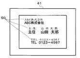
出力装置3は、認識結果または認識信頼度を画面に表示することによって、認識結果をプレビュー画面41に表示してユーザに確認させるための一例としては、図13に示すように、例えば名刺画像中の各文字行領域に沿って、認識した文字(テキスト)50を表示するなどの例がある。この他、文字(テキスト)50の色を変える、文字(テキスト)50を枠で囲んで表示するなど、認識した文字自体を強調するようにしてもよい。 As an example for displaying the recognition result or the recognition reliability on the screen and causing the user to confirm the recognition result by displaying the recognition result on the
また、カメラ1で画像を撮影する場合、レンズ特性などの原因により、画像中心部の画質はよいが、周辺部ではぼやけたり、ゆがんだり、輝度が暗くなるなど画質が劣る場合がある。このようなカメラ1では画像周辺部の画質が悪いため、認識が収束しないことが考えられる。 Further, when an image is taken with the camera 1, the image quality at the center of the image is good due to lens characteristics and the like, but the image quality may be inferior, such as blurring, distortion, or darkness at the periphery. In such a camera 1, since the image quality in the peripheral portion of the image is poor, it is conceivable that the recognition does not converge.
そのように、名刺が認識不可能な状態と判定した場合、認識対象状態判定部23は、カメラ1の撮影範囲内で名刺が認識可能となるよう移動を促す情報を出力装置3へ出力することで、プレビュー画面41に、名刺の位置の移動を促すメッセージを表示させるなどしてユーザに移動指示を与え(ステップS113)、この移動指示(報知)により、ユーザが、未認識の認識対象部分領域の位置を移動させることで、認識の改善を図ることができる。 As such, when it is determined that the business card is unrecognizable, the recognition target
ユーザに対して名刺の位置の移動を促すための表示例としては、例えば図14に示すように、名刺の移動方向の矢印(この例では点線矢印51)および/またはマーク(この例では星印52)などを表示する他、例えば「星が画面中心となるように名刺を移動させてください」などといった文字(この例ではメッセージ53)を表示してもよい。また名刺のガイド枠を移動する、音声を発生して報知するなどの形態をとってもよく、これらの例のうちいずれの方法を用いてもよい。 As a display example for prompting the user to move the position of the business card, for example, as shown in FIG. 14, an arrow (in this example, a dotted arrow 51) and / or a mark (in this example, an asterisk) 52) or the like, for example, characters such as “Please move the business card so that the star is at the center of the screen” (
このようにこの実施形態の画像処理装置によれば、画質の安定した画像が撮りにくい環境で、画像を認識するにあたり、まず名刺画像が得られるたびに認識が可能な認識対象部分領域を検出し、その認識が可能な部分領域から認識処理を行い、部分領域毎に認識結果を蓄積しておき、撮影された順に得られる複数の画像を認識した結果、同じ部分領域の認識結果を統合することで、より安定した高精度の認識結果を得ることができる。 As described above, according to the image processing apparatus of this embodiment, when recognizing an image in an environment where it is difficult to capture an image with stable image quality, first, a recognition target partial region that can be recognized is detected every time a business card image is obtained. , Recognition processing from partial areas that can be recognized, accumulating recognition results for each partial area, recognizing multiple images obtained in the order taken, and integrating the recognition results of the same partial area Thus, a more stable and highly accurate recognition result can be obtained.
なお、本願発明は上記実施形態のみに限定されるものではなく、実施段階ではその要旨を逸脱しない範囲で構成要素を変形してもよい。すなわち、上記実施形態に開示されている複数の構成要素を適宜組み合わせることにより種々の発明を構成できる。また実施形態に示される全構成要素から幾つかの構成要素を削除してもよい。 In addition, this invention is not limited only to the said embodiment, You may deform | transform a component in the range which does not deviate from the summary in an implementation stage. That is, various inventions can be configured by appropriately combining a plurality of constituent elements disclosed in the embodiment. Moreover, you may delete some components from all the components shown by embodiment.
この他、例えばコンピュータのハードディスク装置などのストレージにインストールしたプログラムで各構成要素を実現してもよく、上記プログラムを、コンピュータ読取可能なCD−ROMなどの記憶媒体に記憶しておき、プログラムを記憶媒体からコンピュータに読み取らせることで実現してもよい。さらに、ネットワークを介して接続した異なるコンピュータに構成要素を分散して記憶し、各構成要素を機能させたコンピュータ間で通信することで実現してもよい。 In addition, for example, each component may be realized by a program installed in a storage such as a hard disk device of a computer, and the program is stored in a storage medium such as a computer-readable CD-ROM. You may implement | achieve by making a computer read from a medium. Further, the configuration may be realized by distributing and storing components in different computers connected via a network, and communicating between computers in which the components are functioning.
1…カメラ、2…コンピュータ本体、3…出力装置、20…メモリ、21…受付部、22…メモリ、23…認識対象状態判定部、24…認識対象部分領域検出部、25…移動量検出部、26…画像処理部、27…認識部、28…認識結果統合部、29…認識終了決定部、41…プレビュー画面、42…ガイド枠、43…名刺画像。 DESCRIPTION OF SYMBOLS 1 ... Camera, 2 ... Computer main body, 3 ... Output device, 20 ... Memory, 21 ... Reception part, 22 ... Memory, 23 ... Recognition target state determination part, 24 ... Recognition target partial area detection part, 25 ... Movement amount detection part , 26 ... image processing unit, 27 ... recognition unit, 28 ... recognition result integration unit, 29 ... recognition end determination unit, 41 ... preview screen, 42 ... guide frame, 43 ... business card image.
Claims (7)
Translated fromJapanese前記画像を前記メモリに記録する画像入力部と、
前記画像内に存在する前記認識対象物が認識可能な状態か否かを、予め設定された判定条件に従って判定する認識対象状態判定部と、
前記認識対象状態判定部により認識可能な状態と判定された前記認識対象物の画像領域を検出する認識対象検出部と、
前記メモリに記憶された複数の画像から前記認識対象物の移動量を検出する移動量検出部と、
前記メモリから読み出した前記認識対象物の画像領域から、前記移動量検出部により検出された前記認識対象物の移動量に従って画像領域間の位置の対応をとり、前記画像領域内の認識すべき少なくとも一つの部分領域を検出する部分領域検出部と、
前記部分領域検出部により検出された個々の部分領域に対して認識処理を行い、認識された文字および/またはパターンとその信頼度を前記部分領域毎の認識結果として前記メモリに記憶する認識部と、
撮影時刻の異なる画像領域を認識して得られた同じ部分領域の文字認識結果を前記メモリから読み出し、部分領域毎に時系列として得られる文字認識結果から、部分領域に含まれる文字毎に最も出現割合の高い文字をそれぞれ決定し、それらを連結した文字列を認識結果として出力する認識結果統合部と
を具備することを特徴とする画像処理装置。A memory capable of storing an image of a recognition object photographed by the camera;
An image input unit for recording the image in the memory;
A recognition target state determination unit that determines whether or not the recognition target existing in the image is in a recognizable state according to a predetermined determination condition;
A recognition target detection unit that detects an image area of the recognition target determined to be recognizable by the recognition target state determination unit;
A movement amount detection unit for detecting a movement amount of the recognition object from a plurality of images stored in the memory;
Based on the movement amount of the recognition object detected by the movement amount detection unit from the image area of the recognition object read from the memory,the position between the image areas is matched, and at least the recognition in the image area should be performed. A partial region detection unit for detecting one partial region;
A recognition unit that performs recognition processing on each partial region detected by the partial region detection unit and stores the recognized character and / or pattern and its reliability in the memory as a recognition result for each partial region; ,
The character recognition result of the same partial area obtained by recognizing image areas with different shooting times is read from the memory, and thecharacter recognition result obtained as a time series for each partial area appears most for each character included in the partial area. An image processing apparatus comprising: a recognition result integration unit thatdetermines characters having a high ratio and outputsa character string obtained by connecting the characters as a recognition result.
前記認識対象物を認識不可能な状態と判定した場合、前記画像処理部により高画質化処理された前記認識対象物の画像またはその一部の画像領域を用いて前記認識対象物が認識可能な状態か否かを再判定することを特徴とする請求項2記載の画像処理装置。The recognition target state determination unit
When it is determined that the recognition object is in an unrecognizable state, the recognition object can be recognized using an image of the recognition object or a part of the image area of which the image quality is improved by the image processing unit. The image processing apparatus according to claim2 , wherein the image processing apparatus re-determines whether or not the state is satisfied.
前記認識対象状態判定部が前記認識対象物を認識不可能な状態と判定した場合、前記画像処理部により高画質化処理された前記認識対象物の画像またはその一部の画像領域を用いて再認識することを特徴とする請求項2記載の画像処理装置。The recognition unit
When the recognition target state determination unit determines that the recognition target is in an unrecognizable state, the recognition target state determination unit re-uses the recognition target image or a part of the image area that has been subjected to high image quality processing by the image processing unit. The image processing apparatus according to claim2 , wherein the image processing apparatus recognizes the image.
前記認識対象物の画像領域が認識不可能な状態と判定した場合、前記カメラの撮影範囲内で前記認識対象物が認識可能となるよう移動を促す情報を出力することを特徴とする請求項1記載の画像処理装置。The recognition target state determination unit
2. When it is determined that the image area of the recognition object is in an unrecognizable state, information for urging movement is output so that the recognition object can be recognized within a shooting range of the camera. The image processing apparatus described.
Priority Applications (2)
| Application Number | Priority Date | Filing Date | Title |
|---|---|---|---|
| JP2009062044AJP4875117B2 (en) | 2009-03-13 | 2009-03-13 | Image processing device |
| US12/723,000US8289403B2 (en) | 2009-03-13 | 2010-03-12 | Image processing system |
Applications Claiming Priority (1)
| Application Number | Priority Date | Filing Date | Title |
|---|---|---|---|
| JP2009062044AJP4875117B2 (en) | 2009-03-13 | 2009-03-13 | Image processing device |
Publications (2)
| Publication Number | Publication Date |
|---|---|
| JP2010218061A JP2010218061A (en) | 2010-09-30 |
| JP4875117B2true JP4875117B2 (en) | 2012-02-15 |
Family
ID=42730369
Family Applications (1)
| Application Number | Title | Priority Date | Filing Date |
|---|---|---|---|
| JP2009062044AExpired - Fee RelatedJP4875117B2 (en) | 2009-03-13 | 2009-03-13 | Image processing device |
Country Status (2)
| Country | Link |
|---|---|
| US (1) | US8289403B2 (en) |
| JP (1) | JP4875117B2 (en) |
Cited By (1)
| Publication number | Priority date | Publication date | Assignee | Title |
|---|---|---|---|---|
| RU2727464C1 (en)* | 2016-12-28 | 2020-07-21 | Омрон Хэлткэа Ко., Лтд. | Terminal device |
Families Citing this family (403)
| Publication number | Priority date | Publication date | Assignee | Title |
|---|---|---|---|---|
| US20070084897A1 (en) | 2003-05-20 | 2007-04-19 | Shelton Frederick E Iv | Articulating surgical stapling instrument incorporating a two-piece e-beam firing mechanism |
| US9060770B2 (en) | 2003-05-20 | 2015-06-23 | Ethicon Endo-Surgery, Inc. | Robotically-driven surgical instrument with E-beam driver |
| US11890012B2 (en) | 2004-07-28 | 2024-02-06 | Cilag Gmbh International | Staple cartridge comprising cartridge body and attached support |
| US8215531B2 (en) | 2004-07-28 | 2012-07-10 | Ethicon Endo-Surgery, Inc. | Surgical stapling instrument having a medical substance dispenser |
| US11998198B2 (en) | 2004-07-28 | 2024-06-04 | Cilag Gmbh International | Surgical stapling instrument incorporating a two-piece E-beam firing mechanism |
| US9072535B2 (en) | 2011-05-27 | 2015-07-07 | Ethicon Endo-Surgery, Inc. | Surgical stapling instruments with rotatable staple deployment arrangements |
| US9237891B2 (en) | 2005-08-31 | 2016-01-19 | Ethicon Endo-Surgery, Inc. | Robotically-controlled surgical stapling devices that produce formed staples having different lengths |
| US11484312B2 (en) | 2005-08-31 | 2022-11-01 | Cilag Gmbh International | Staple cartridge comprising a staple driver arrangement |
| US10159482B2 (en) | 2005-08-31 | 2018-12-25 | Ethicon Llc | Fastener cartridge assembly comprising a fixed anvil and different staple heights |
| US7669746B2 (en) | 2005-08-31 | 2010-03-02 | Ethicon Endo-Surgery, Inc. | Staple cartridges for forming staples having differing formed staple heights |
| US7934630B2 (en) | 2005-08-31 | 2011-05-03 | Ethicon Endo-Surgery, Inc. | Staple cartridges for forming staples having differing formed staple heights |
| US11246590B2 (en) | 2005-08-31 | 2022-02-15 | Cilag Gmbh International | Staple cartridge including staple drivers having different unfired heights |
| US20070106317A1 (en) | 2005-11-09 | 2007-05-10 | Shelton Frederick E Iv | Hydraulically and electrically actuated articulation joints for surgical instruments |
| US8186555B2 (en) | 2006-01-31 | 2012-05-29 | Ethicon Endo-Surgery, Inc. | Motor-driven surgical cutting and fastening instrument with mechanical closure system |
| US20120292367A1 (en) | 2006-01-31 | 2012-11-22 | Ethicon Endo-Surgery, Inc. | Robotically-controlled end effector |
| US11278279B2 (en) | 2006-01-31 | 2022-03-22 | Cilag Gmbh International | Surgical instrument assembly |
| US7845537B2 (en) | 2006-01-31 | 2010-12-07 | Ethicon Endo-Surgery, Inc. | Surgical instrument having recording capabilities |
| US8708213B2 (en) | 2006-01-31 | 2014-04-29 | Ethicon Endo-Surgery, Inc. | Surgical instrument having a feedback system |
| US8820603B2 (en) | 2006-01-31 | 2014-09-02 | Ethicon Endo-Surgery, Inc. | Accessing data stored in a memory of a surgical instrument |
| US7753904B2 (en) | 2006-01-31 | 2010-07-13 | Ethicon Endo-Surgery, Inc. | Endoscopic surgical instrument with a handle that can articulate with respect to the shaft |
| US20110024477A1 (en) | 2009-02-06 | 2011-02-03 | Hall Steven G | Driven Surgical Stapler Improvements |
| US11793518B2 (en) | 2006-01-31 | 2023-10-24 | Cilag Gmbh International | Powered surgical instruments with firing system lockout arrangements |
| US20110295295A1 (en) | 2006-01-31 | 2011-12-01 | Ethicon Endo-Surgery, Inc. | Robotically-controlled surgical instrument having recording capabilities |
| US11224427B2 (en) | 2006-01-31 | 2022-01-18 | Cilag Gmbh International | Surgical stapling system including a console and retraction assembly |
| US8992422B2 (en) | 2006-03-23 | 2015-03-31 | Ethicon Endo-Surgery, Inc. | Robotically-controlled endoscopic accessory channel |
| US8322455B2 (en) | 2006-06-27 | 2012-12-04 | Ethicon Endo-Surgery, Inc. | Manually driven surgical cutting and fastening instrument |
| US10568652B2 (en) | 2006-09-29 | 2020-02-25 | Ethicon Llc | Surgical staples having attached drivers of different heights and stapling instruments for deploying the same |
| US11980366B2 (en) | 2006-10-03 | 2024-05-14 | Cilag Gmbh International | Surgical instrument |
| US8684253B2 (en) | 2007-01-10 | 2014-04-01 | Ethicon Endo-Surgery, Inc. | Surgical instrument with wireless communication between a control unit of a robotic system and remote sensor |
| US8632535B2 (en) | 2007-01-10 | 2014-01-21 | Ethicon Endo-Surgery, Inc. | Interlock and surgical instrument including same |
| US11291441B2 (en) | 2007-01-10 | 2022-04-05 | Cilag Gmbh International | Surgical instrument with wireless communication between control unit and remote sensor |
| US20080169333A1 (en) | 2007-01-11 | 2008-07-17 | Shelton Frederick E | Surgical stapler end effector with tapered distal end |
| US11039836B2 (en) | 2007-01-11 | 2021-06-22 | Cilag Gmbh International | Staple cartridge for use with a surgical stapling instrument |
| US7673782B2 (en) | 2007-03-15 | 2010-03-09 | Ethicon Endo-Surgery, Inc. | Surgical stapling instrument having a releasable buttress material |
| US11564682B2 (en) | 2007-06-04 | 2023-01-31 | Cilag Gmbh International | Surgical stapler device |
| US8931682B2 (en) | 2007-06-04 | 2015-01-13 | Ethicon Endo-Surgery, Inc. | Robotically-controlled shaft based rotary drive systems for surgical instruments |
| US7753245B2 (en) | 2007-06-22 | 2010-07-13 | Ethicon Endo-Surgery, Inc. | Surgical stapling instruments |
| US11849941B2 (en) | 2007-06-29 | 2023-12-26 | Cilag Gmbh International | Staple cartridge having staple cavities extending at a transverse angle relative to a longitudinal cartridge axis |
| US8573465B2 (en) | 2008-02-14 | 2013-11-05 | Ethicon Endo-Surgery, Inc. | Robotically-controlled surgical end effector system with rotary actuated closure systems |
| US11986183B2 (en) | 2008-02-14 | 2024-05-21 | Cilag Gmbh International | Surgical cutting and fastening instrument comprising a plurality of sensors to measure an electrical parameter |
| US7819298B2 (en) | 2008-02-14 | 2010-10-26 | Ethicon Endo-Surgery, Inc. | Surgical stapling apparatus with control features operable with one hand |
| US9179912B2 (en) | 2008-02-14 | 2015-11-10 | Ethicon Endo-Surgery, Inc. | Robotically-controlled motorized surgical cutting and fastening instrument |
| US7866527B2 (en) | 2008-02-14 | 2011-01-11 | Ethicon Endo-Surgery, Inc. | Surgical stapling apparatus with interlockable firing system |
| US8758391B2 (en) | 2008-02-14 | 2014-06-24 | Ethicon Endo-Surgery, Inc. | Interchangeable tools for surgical instruments |
| JP5410110B2 (en) | 2008-02-14 | 2014-02-05 | エシコン・エンド−サージェリィ・インコーポレイテッド | Surgical cutting / fixing instrument with RF electrode |
| US8636736B2 (en) | 2008-02-14 | 2014-01-28 | Ethicon Endo-Surgery, Inc. | Motorized surgical cutting and fastening instrument |
| US9585657B2 (en) | 2008-02-15 | 2017-03-07 | Ethicon Endo-Surgery, Llc | Actuator for releasing a layer of material from a surgical end effector |
| US11648005B2 (en) | 2008-09-23 | 2023-05-16 | Cilag Gmbh International | Robotically-controlled motorized surgical instrument with an end effector |
| US9386983B2 (en) | 2008-09-23 | 2016-07-12 | Ethicon Endo-Surgery, Llc | Robotically-controlled motorized surgical instrument |
| US8210411B2 (en) | 2008-09-23 | 2012-07-03 | Ethicon Endo-Surgery, Inc. | Motor-driven surgical cutting instrument |
| US9005230B2 (en) | 2008-09-23 | 2015-04-14 | Ethicon Endo-Surgery, Inc. | Motorized surgical instrument |
| US8608045B2 (en) | 2008-10-10 | 2013-12-17 | Ethicon Endo-Sugery, Inc. | Powered surgical cutting and stapling apparatus with manually retractable firing system |
| US8517239B2 (en) | 2009-02-05 | 2013-08-27 | Ethicon Endo-Surgery, Inc. | Surgical stapling instrument comprising a magnetic element driver |
| RU2525225C2 (en) | 2009-02-06 | 2014-08-10 | Этикон Эндо-Серджери, Инк. | Improvement of drive surgical suturing instrument |
| US8851354B2 (en) | 2009-12-24 | 2014-10-07 | Ethicon Endo-Surgery, Inc. | Surgical cutting instrument that analyzes tissue thickness |
| US8220688B2 (en) | 2009-12-24 | 2012-07-17 | Ethicon Endo-Surgery, Inc. | Motor-driven surgical cutting instrument with electric actuator directional control assembly |
| TW201203129A (en)* | 2010-07-09 | 2012-01-16 | Primax Electronics Ltd | Image pickup system |
| US8783543B2 (en) | 2010-07-30 | 2014-07-22 | Ethicon Endo-Surgery, Inc. | Tissue acquisition arrangements and methods for surgical stapling devices |
| US9386988B2 (en) | 2010-09-30 | 2016-07-12 | Ethicon End-Surgery, LLC | Retainer assembly including a tissue thickness compensator |
| US9016542B2 (en) | 2010-09-30 | 2015-04-28 | Ethicon Endo-Surgery, Inc. | Staple cartridge comprising compressible distortion resistant components |
| US9788834B2 (en) | 2010-09-30 | 2017-10-17 | Ethicon Llc | Layer comprising deployable attachment members |
| US9629814B2 (en) | 2010-09-30 | 2017-04-25 | Ethicon Endo-Surgery, Llc | Tissue thickness compensator configured to redistribute compressive forces |
| US11298125B2 (en) | 2010-09-30 | 2022-04-12 | Cilag Gmbh International | Tissue stapler having a thickness compensator |
| US10945731B2 (en) | 2010-09-30 | 2021-03-16 | Ethicon Llc | Tissue thickness compensator comprising controlled release and expansion |
| US9351730B2 (en) | 2011-04-29 | 2016-05-31 | Ethicon Endo-Surgery, Llc | Tissue thickness compensator comprising channels |
| US11812965B2 (en) | 2010-09-30 | 2023-11-14 | Cilag Gmbh International | Layer of material for a surgical end effector |
| US12213666B2 (en) | 2010-09-30 | 2025-02-04 | Cilag Gmbh International | Tissue thickness compensator comprising layers |
| US11925354B2 (en) | 2010-09-30 | 2024-03-12 | Cilag Gmbh International | Staple cartridge comprising staples positioned within a compressible portion thereof |
| US8695866B2 (en) | 2010-10-01 | 2014-04-15 | Ethicon Endo-Surgery, Inc. | Surgical instrument having a power control circuit |
| JP2012205089A (en)* | 2011-03-25 | 2012-10-22 | Toshiba Corp | Information processing device, information processing method, and information processing program |
| AU2012250197B2 (en) | 2011-04-29 | 2017-08-10 | Ethicon Endo-Surgery, Inc. | Staple cartridge comprising staples positioned within a compressible portion thereof |
| US11207064B2 (en) | 2011-05-27 | 2021-12-28 | Cilag Gmbh International | Automated end effector component reloading system for use with a robotic system |
| US9418304B2 (en) | 2011-06-29 | 2016-08-16 | Qualcomm Incorporated | System and method for recognizing text information in object |
| JP5982844B2 (en)* | 2012-02-06 | 2016-08-31 | オムロン株式会社 | Character reading program and character reading device |
| US9044230B2 (en) | 2012-02-13 | 2015-06-02 | Ethicon Endo-Surgery, Inc. | Surgical cutting and fastening instrument with apparatus for determining cartridge and firing motion status |
| JP6224070B2 (en) | 2012-03-28 | 2017-11-01 | エシコン・エンド−サージェリィ・インコーポレイテッドEthicon Endo−Surgery,Inc. | Retainer assembly including tissue thickness compensator |
| BR112014024098B1 (en) | 2012-03-28 | 2021-05-25 | Ethicon Endo-Surgery, Inc. | staple cartridge |
| MX358135B (en) | 2012-03-28 | 2018-08-06 | Ethicon Endo Surgery Inc | Tissue thickness compensator comprising a plurality of layers. |
| US9101358B2 (en) | 2012-06-15 | 2015-08-11 | Ethicon Endo-Surgery, Inc. | Articulatable surgical instrument comprising a firing drive |
| US20140001231A1 (en) | 2012-06-28 | 2014-01-02 | Ethicon Endo-Surgery, Inc. | Firing system lockout arrangements for surgical instruments |
| US9282974B2 (en) | 2012-06-28 | 2016-03-15 | Ethicon Endo-Surgery, Llc | Empty clip cartridge lockout |
| JP6290201B2 (en) | 2012-06-28 | 2018-03-07 | エシコン・エンド−サージェリィ・インコーポレイテッドEthicon Endo−Surgery,Inc. | Lockout for empty clip cartridge |
| US9289256B2 (en) | 2012-06-28 | 2016-03-22 | Ethicon Endo-Surgery, Llc | Surgical end effectors having angled tissue-contacting surfaces |
| US12383267B2 (en) | 2012-06-28 | 2025-08-12 | Cilag Gmbh International | Robotically powered surgical device with manually-actuatable reversing system |
| US11278284B2 (en) | 2012-06-28 | 2022-03-22 | Cilag Gmbh International | Rotary drive arrangements for surgical instruments |
| BR112014032776B1 (en) | 2012-06-28 | 2021-09-08 | Ethicon Endo-Surgery, Inc | SURGICAL INSTRUMENT SYSTEM AND SURGICAL KIT FOR USE WITH A SURGICAL INSTRUMENT SYSTEM |
| US9408606B2 (en) | 2012-06-28 | 2016-08-09 | Ethicon Endo-Surgery, Llc | Robotically powered surgical device with manually-actuatable reversing system |
| RU2672520C2 (en) | 2013-03-01 | 2018-11-15 | Этикон Эндо-Серджери, Инк. | Hingedly turnable surgical instruments with conducting ways for signal transfer |
| BR112015021082B1 (en) | 2013-03-01 | 2022-05-10 | Ethicon Endo-Surgery, Inc | surgical instrument |
| US9629629B2 (en) | 2013-03-14 | 2017-04-25 | Ethicon Endo-Surgey, LLC | Control systems for surgical instruments |
| US9808244B2 (en) | 2013-03-14 | 2017-11-07 | Ethicon Llc | Sensor arrangements for absolute positioning system for surgical instruments |
| US9826976B2 (en) | 2013-04-16 | 2017-11-28 | Ethicon Llc | Motor driven surgical instruments with lockable dual drive shafts |
| BR112015026109B1 (en) | 2013-04-16 | 2022-02-22 | Ethicon Endo-Surgery, Inc | surgical instrument |
| CN104217202B (en)* | 2013-06-03 | 2019-01-01 | 支付宝(中国)网络技术有限公司 | Information identification method, equipment and system |
| RU2538941C1 (en) | 2013-06-14 | 2015-01-10 | Общество с ограниченной ответственностью "Аби Девелопмент" | Recognition quality enhancements by increasing image resolution |
| KR20150018264A (en) | 2013-08-09 | 2015-02-23 | 엘지전자 주식회사 | Wearable glass-type device and control method thereof |
| US9775609B2 (en) | 2013-08-23 | 2017-10-03 | Ethicon Llc | Tamper proof circuit for surgical instrument battery pack |
| MX369362B (en) | 2013-08-23 | 2019-11-06 | Ethicon Endo Surgery Llc | Firing member retraction devices for powered surgical instruments. |
| US9962161B2 (en) | 2014-02-12 | 2018-05-08 | Ethicon Llc | Deliverable surgical instrument |
| CN106104195B (en)* | 2014-03-13 | 2019-01-29 | 株式会社富士 | Image processing apparatus and substrate production system |
| US10004497B2 (en) | 2014-03-26 | 2018-06-26 | Ethicon Llc | Interface systems for use with surgical instruments |
| US10013049B2 (en) | 2014-03-26 | 2018-07-03 | Ethicon Llc | Power management through sleep options of segmented circuit and wake up control |
| BR112016021943B1 (en) | 2014-03-26 | 2022-06-14 | Ethicon Endo-Surgery, Llc | SURGICAL INSTRUMENT FOR USE BY AN OPERATOR IN A SURGICAL PROCEDURE |
| US20150272580A1 (en) | 2014-03-26 | 2015-10-01 | Ethicon Endo-Surgery, Inc. | Verification of number of battery exchanges/procedure count |
| US12232723B2 (en) | 2014-03-26 | 2025-02-25 | Cilag Gmbh International | Systems and methods for controlling a segmented circuit |
| CN106456159B (en) | 2014-04-16 | 2019-03-08 | 伊西康内外科有限责任公司 | Fastener Cartridge Assembly and Nail Retainer Cover Arrangement |
| BR112016023825B1 (en) | 2014-04-16 | 2022-08-02 | Ethicon Endo-Surgery, Llc | STAPLE CARTRIDGE FOR USE WITH A SURGICAL STAPLER AND STAPLE CARTRIDGE FOR USE WITH A SURGICAL INSTRUMENT |
| CN106456176B (en) | 2014-04-16 | 2019-06-28 | 伊西康内外科有限责任公司 | Fastener Cartridge Including Extensions With Different Configurations |
| US20150297225A1 (en) | 2014-04-16 | 2015-10-22 | Ethicon Endo-Surgery, Inc. | Fastener cartridges including extensions having different configurations |
| US10327764B2 (en) | 2014-09-26 | 2019-06-25 | Ethicon Llc | Method for creating a flexible staple line |
| US10470768B2 (en) | 2014-04-16 | 2019-11-12 | Ethicon Llc | Fastener cartridge including a layer attached thereto |
| US9602728B2 (en) | 2014-06-09 | 2017-03-21 | Qualcomm Incorporated | Image capturing parameter adjustment in preview mode |
| US11311294B2 (en) | 2014-09-05 | 2022-04-26 | Cilag Gmbh International | Powered medical device including measurement of closure state of jaws |
| BR112017004361B1 (en) | 2014-09-05 | 2023-04-11 | Ethicon Llc | ELECTRONIC SYSTEM FOR A SURGICAL INSTRUMENT |
| US10135242B2 (en) | 2014-09-05 | 2018-11-20 | Ethicon Llc | Smart cartridge wake up operation and data retention |
| US10105142B2 (en) | 2014-09-18 | 2018-10-23 | Ethicon Llc | Surgical stapler with plurality of cutting elements |
| US11523821B2 (en) | 2014-09-26 | 2022-12-13 | Cilag Gmbh International | Method for creating a flexible staple line |
| CN107427300B (en) | 2014-09-26 | 2020-12-04 | 伊西康有限责任公司 | Surgical suture buttresses and auxiliary materials |
| US10076325B2 (en) | 2014-10-13 | 2018-09-18 | Ethicon Llc | Surgical stapling apparatus comprising a tissue stop |
| US9924944B2 (en) | 2014-10-16 | 2018-03-27 | Ethicon Llc | Staple cartridge comprising an adjunct material |
| US11141153B2 (en) | 2014-10-29 | 2021-10-12 | Cilag Gmbh International | Staple cartridges comprising driver arrangements |
| US10517594B2 (en) | 2014-10-29 | 2019-12-31 | Ethicon Llc | Cartridge assemblies for surgical staplers |
| US9844376B2 (en) | 2014-11-06 | 2017-12-19 | Ethicon Llc | Staple cartridge comprising a releasable adjunct material |
| US20170272623A1 (en)* | 2014-12-03 | 2017-09-21 | Nec Corporation | Direction control device, direction control method and recording medium |
| US10736636B2 (en) | 2014-12-10 | 2020-08-11 | Ethicon Llc | Articulatable surgical instrument system |
| US9844374B2 (en) | 2014-12-18 | 2017-12-19 | Ethicon Llc | Surgical instrument systems comprising an articulatable end effector and means for adjusting the firing stroke of a firing member |
| US9943309B2 (en) | 2014-12-18 | 2018-04-17 | Ethicon Llc | Surgical instruments with articulatable end effectors and movable firing beam support arrangements |
| US9987000B2 (en) | 2014-12-18 | 2018-06-05 | Ethicon Llc | Surgical instrument assembly comprising a flexible articulation system |
| US9844375B2 (en) | 2014-12-18 | 2017-12-19 | Ethicon Llc | Drive arrangements for articulatable surgical instruments |
| MX389118B (en) | 2014-12-18 | 2025-03-20 | Ethicon Llc | SURGICAL INSTRUMENT WITH AN ANVIL THAT CAN BE SELECTIVELY MOVED ON A DISCRETE, NON-MOBILE AXIS RELATIVE TO A STAPLE CARTRIDGE. |
| US10085748B2 (en) | 2014-12-18 | 2018-10-02 | Ethicon Llc | Locking arrangements for detachable shaft assemblies with articulatable surgical end effectors |
| US11154301B2 (en) | 2015-02-27 | 2021-10-26 | Cilag Gmbh International | Modular stapling assembly |
| US10617412B2 (en) | 2015-03-06 | 2020-04-14 | Ethicon Llc | System for detecting the mis-insertion of a staple cartridge into a surgical stapler |
| JP2020121162A (en) | 2015-03-06 | 2020-08-13 | エシコン エルエルシーEthicon LLC | Time dependent evaluation of sensor data to determine stability element, creep element and viscoelastic element of measurement |
| US9993248B2 (en) | 2015-03-06 | 2018-06-12 | Ethicon Endo-Surgery, Llc | Smart sensors with local signal processing |
| US10687806B2 (en) | 2015-03-06 | 2020-06-23 | Ethicon Llc | Adaptive tissue compression techniques to adjust closure rates for multiple tissue types |
| US9901342B2 (en) | 2015-03-06 | 2018-02-27 | Ethicon Endo-Surgery, Llc | Signal and power communication system positioned on a rotatable shaft |
| US10245033B2 (en) | 2015-03-06 | 2019-04-02 | Ethicon Llc | Surgical instrument comprising a lockable battery housing |
| US10441279B2 (en) | 2015-03-06 | 2019-10-15 | Ethicon Llc | Multiple level thresholds to modify operation of powered surgical instruments |
| US10548504B2 (en) | 2015-03-06 | 2020-02-04 | Ethicon Llc | Overlaid multi sensor radio frequency (RF) electrode system to measure tissue compression |
| US10433844B2 (en) | 2015-03-31 | 2019-10-08 | Ethicon Llc | Surgical instrument with selectively disengageable threaded drive systems |
| US10835249B2 (en) | 2015-08-17 | 2020-11-17 | Ethicon Llc | Implantable layers for a surgical instrument |
| US10105139B2 (en) | 2015-09-23 | 2018-10-23 | Ethicon Llc | Surgical stapler having downstream current-based motor control |
| US10238386B2 (en) | 2015-09-23 | 2019-03-26 | Ethicon Llc | Surgical stapler having motor control based on an electrical parameter related to a motor current |
| US10299878B2 (en) | 2015-09-25 | 2019-05-28 | Ethicon Llc | Implantable adjunct systems for determining adjunct skew |
| US10433846B2 (en) | 2015-09-30 | 2019-10-08 | Ethicon Llc | Compressible adjunct with crossing spacer fibers |
| US10478188B2 (en) | 2015-09-30 | 2019-11-19 | Ethicon Llc | Implantable layer comprising a constricted configuration |
| US11890015B2 (en) | 2015-09-30 | 2024-02-06 | Cilag Gmbh International | Compressible adjunct with crossing spacer fibers |
| US10980539B2 (en) | 2015-09-30 | 2021-04-20 | Ethicon Llc | Implantable adjunct comprising bonded layers |
| US10292704B2 (en) | 2015-12-30 | 2019-05-21 | Ethicon Llc | Mechanisms for compensating for battery pack failure in powered surgical instruments |
| US10368865B2 (en) | 2015-12-30 | 2019-08-06 | Ethicon Llc | Mechanisms for compensating for drivetrain failure in powered surgical instruments |
| US10265068B2 (en) | 2015-12-30 | 2019-04-23 | Ethicon Llc | Surgical instruments with separable motors and motor control circuits |
| US11213293B2 (en) | 2016-02-09 | 2022-01-04 | Cilag Gmbh International | Articulatable surgical instruments with single articulation link arrangements |
| BR112018016098B1 (en) | 2016-02-09 | 2023-02-23 | Ethicon Llc | SURGICAL INSTRUMENT |
| US11224426B2 (en) | 2016-02-12 | 2022-01-18 | Cilag Gmbh International | Mechanisms for compensating for drivetrain failure in powered surgical instruments |
| US10448948B2 (en) | 2016-02-12 | 2019-10-22 | Ethicon Llc | Mechanisms for compensating for drivetrain failure in powered surgical instruments |
| JP6679350B2 (en)* | 2016-03-09 | 2020-04-15 | キヤノン株式会社 | Information processing apparatus, program, and information processing method |
| US10357247B2 (en) | 2016-04-15 | 2019-07-23 | Ethicon Llc | Surgical instrument with multiple program responses during a firing motion |
| US10335145B2 (en) | 2016-04-15 | 2019-07-02 | Ethicon Llc | Modular surgical instrument with configurable operating mode |
| US11179150B2 (en) | 2016-04-15 | 2021-11-23 | Cilag Gmbh International | Systems and methods for controlling a surgical stapling and cutting instrument |
| US10828028B2 (en) | 2016-04-15 | 2020-11-10 | Ethicon Llc | Surgical instrument with multiple program responses during a firing motion |
| US10426467B2 (en) | 2016-04-15 | 2019-10-01 | Ethicon Llc | Surgical instrument with detection sensors |
| US10456137B2 (en) | 2016-04-15 | 2019-10-29 | Ethicon Llc | Staple formation detection mechanisms |
| US11607239B2 (en) | 2016-04-15 | 2023-03-21 | Cilag Gmbh International | Systems and methods for controlling a surgical stapling and cutting instrument |
| US10492783B2 (en) | 2016-04-15 | 2019-12-03 | Ethicon, Llc | Surgical instrument with improved stop/start control during a firing motion |
| US20170296173A1 (en) | 2016-04-18 | 2017-10-19 | Ethicon Endo-Surgery, Llc | Method for operating a surgical instrument |
| US10363037B2 (en) | 2016-04-18 | 2019-07-30 | Ethicon Llc | Surgical instrument system comprising a magnetic lockout |
| US11317917B2 (en) | 2016-04-18 | 2022-05-03 | Cilag Gmbh International | Surgical stapling system comprising a lockable firing assembly |
| US10500000B2 (en) | 2016-08-16 | 2019-12-10 | Ethicon Llc | Surgical tool with manual control of end effector jaws |
| US10758229B2 (en) | 2016-12-21 | 2020-09-01 | Ethicon Llc | Surgical instrument comprising improved jaw control |
| US10485543B2 (en) | 2016-12-21 | 2019-11-26 | Ethicon Llc | Anvil having a knife slot width |
| US20180168615A1 (en) | 2016-12-21 | 2018-06-21 | Ethicon Endo-Surgery, Llc | Method of deforming staples from two different types of staple cartridges with the same surgical stapling instrument |
| MX2019007295A (en) | 2016-12-21 | 2019-10-15 | Ethicon Llc | Surgical instrument system comprising an end effector lockout and a firing assembly lockout. |
| JP7010957B2 (en) | 2016-12-21 | 2022-01-26 | エシコン エルエルシー | Shaft assembly with lockout |
| US10542982B2 (en) | 2016-12-21 | 2020-01-28 | Ethicon Llc | Shaft assembly comprising first and second articulation lockouts |
| JP2020501815A (en) | 2016-12-21 | 2020-01-23 | エシコン エルエルシーEthicon LLC | Surgical stapling system |
| JP7010956B2 (en) | 2016-12-21 | 2022-01-26 | エシコン エルエルシー | How to staple tissue |
| US10980536B2 (en) | 2016-12-21 | 2021-04-20 | Ethicon Llc | No-cartridge and spent cartridge lockout arrangements for surgical staplers |
| US10568625B2 (en) | 2016-12-21 | 2020-02-25 | Ethicon Llc | Staple cartridges and arrangements of staples and staple cavities therein |
| US20180168625A1 (en) | 2016-12-21 | 2018-06-21 | Ethicon Endo-Surgery, Llc | Surgical stapling instruments with smart staple cartridges |
| CN110087565A (en) | 2016-12-21 | 2019-08-02 | 爱惜康有限责任公司 | Surgical stapling system |
| US11419606B2 (en) | 2016-12-21 | 2022-08-23 | Cilag Gmbh International | Shaft assembly comprising a clutch configured to adapt the output of a rotary firing member to two different systems |
| JP6983893B2 (en) | 2016-12-21 | 2021-12-17 | エシコン エルエルシーEthicon LLC | Lockout configuration for surgical end effectors and replaceable tool assemblies |
| US10695055B2 (en) | 2016-12-21 | 2020-06-30 | Ethicon Llc | Firing assembly comprising a lockout |
| US10813638B2 (en) | 2016-12-21 | 2020-10-27 | Ethicon Llc | Surgical end effectors with expandable tissue stop arrangements |
| US10898186B2 (en) | 2016-12-21 | 2021-01-26 | Ethicon Llc | Staple forming pocket arrangements comprising primary sidewalls and pocket sidewalls |
| US10582928B2 (en) | 2016-12-21 | 2020-03-10 | Ethicon Llc | Articulation lock arrangements for locking an end effector in an articulated position in response to actuation of a jaw closure system |
| US10973516B2 (en) | 2016-12-21 | 2021-04-13 | Ethicon Llc | Surgical end effectors and adaptable firing members therefor |
| US11090048B2 (en) | 2016-12-21 | 2021-08-17 | Cilag Gmbh International | Method for resetting a fuse of a surgical instrument shaft |
| US11134942B2 (en) | 2016-12-21 | 2021-10-05 | Cilag Gmbh International | Surgical stapling instruments and staple-forming anvils |
| JP6614186B2 (en)* | 2017-03-21 | 2019-12-04 | カシオ計算機株式会社 | Book document processing apparatus, book document processing method, and program |
| USD879808S1 (en) | 2017-06-20 | 2020-03-31 | Ethicon Llc | Display panel with graphical user interface |
| US10881396B2 (en) | 2017-06-20 | 2021-01-05 | Ethicon Llc | Surgical instrument with variable duration trigger arrangement |
| US10813639B2 (en) | 2017-06-20 | 2020-10-27 | Ethicon Llc | Closed loop feedback control of motor velocity of a surgical stapling and cutting instrument based on system conditions |
| USD890784S1 (en) | 2017-06-20 | 2020-07-21 | Ethicon Llc | Display panel with changeable graphical user interface |
| US11382638B2 (en) | 2017-06-20 | 2022-07-12 | Cilag Gmbh International | Closed loop feedback control of motor velocity of a surgical stapling and cutting instrument based on measured time over a specified displacement distance |
| US11090046B2 (en) | 2017-06-20 | 2021-08-17 | Cilag Gmbh International | Systems and methods for controlling displacement member motion of a surgical stapling and cutting instrument |
| US11071554B2 (en) | 2017-06-20 | 2021-07-27 | Cilag Gmbh International | Closed loop feedback control of motor velocity of a surgical stapling and cutting instrument based on magnitude of velocity error measurements |
| US10646220B2 (en) | 2017-06-20 | 2020-05-12 | Ethicon Llc | Systems and methods for controlling displacement member velocity for a surgical instrument |
| US11653914B2 (en) | 2017-06-20 | 2023-05-23 | Cilag Gmbh International | Systems and methods for controlling motor velocity of a surgical stapling and cutting instrument according to articulation angle of end effector |
| USD879809S1 (en) | 2017-06-20 | 2020-03-31 | Ethicon Llc | Display panel with changeable graphical user interface |
| US10881399B2 (en) | 2017-06-20 | 2021-01-05 | Ethicon Llc | Techniques for adaptive control of motor velocity of a surgical stapling and cutting instrument |
| US10779820B2 (en) | 2017-06-20 | 2020-09-22 | Ethicon Llc | Systems and methods for controlling motor speed according to user input for a surgical instrument |
| US10980537B2 (en) | 2017-06-20 | 2021-04-20 | Ethicon Llc | Closed loop feedback control of motor velocity of a surgical stapling and cutting instrument based on measured time over a specified number of shaft rotations |
| US11517325B2 (en) | 2017-06-20 | 2022-12-06 | Cilag Gmbh International | Closed loop feedback control of motor velocity of a surgical stapling and cutting instrument based on measured displacement distance traveled over a specified time interval |
| US10307170B2 (en) | 2017-06-20 | 2019-06-04 | Ethicon Llc | Method for closed loop control of motor velocity of a surgical stapling and cutting instrument |
| US10888321B2 (en) | 2017-06-20 | 2021-01-12 | Ethicon Llc | Systems and methods for controlling velocity of a displacement member of a surgical stapling and cutting instrument |
| US10772629B2 (en) | 2017-06-27 | 2020-09-15 | Ethicon Llc | Surgical anvil arrangements |
| US11090049B2 (en) | 2017-06-27 | 2021-08-17 | Cilag Gmbh International | Staple forming pocket arrangements |
| US10993716B2 (en) | 2017-06-27 | 2021-05-04 | Ethicon Llc | Surgical anvil arrangements |
| US11324503B2 (en) | 2017-06-27 | 2022-05-10 | Cilag Gmbh International | Surgical firing member arrangements |
| US11266405B2 (en) | 2017-06-27 | 2022-03-08 | Cilag Gmbh International | Surgical anvil manufacturing methods |
| US10856869B2 (en) | 2017-06-27 | 2020-12-08 | Ethicon Llc | Surgical anvil arrangements |
| US10716614B2 (en) | 2017-06-28 | 2020-07-21 | Ethicon Llc | Surgical shaft assemblies with slip ring assemblies with increased contact pressure |
| USD906355S1 (en) | 2017-06-28 | 2020-12-29 | Ethicon Llc | Display screen or portion thereof with a graphical user interface for a surgical instrument |
| US11484310B2 (en) | 2017-06-28 | 2022-11-01 | Cilag Gmbh International | Surgical instrument comprising a shaft including a closure tube profile |
| US10765427B2 (en) | 2017-06-28 | 2020-09-08 | Ethicon Llc | Method for articulating a surgical instrument |
| US11259805B2 (en) | 2017-06-28 | 2022-03-01 | Cilag Gmbh International | Surgical instrument comprising firing member supports |
| US10903685B2 (en) | 2017-06-28 | 2021-01-26 | Ethicon Llc | Surgical shaft assemblies with slip ring assemblies forming capacitive channels |
| US10758232B2 (en) | 2017-06-28 | 2020-09-01 | Ethicon Llc | Surgical instrument with positive jaw opening features |
| US11246592B2 (en) | 2017-06-28 | 2022-02-15 | Cilag Gmbh International | Surgical instrument comprising an articulation system lockable to a frame |
| EP3420947B1 (en) | 2017-06-28 | 2022-05-25 | Cilag GmbH International | Surgical instrument comprising selectively actuatable rotatable couplers |
| US11564686B2 (en) | 2017-06-28 | 2023-01-31 | Cilag Gmbh International | Surgical shaft assemblies with flexible interfaces |
| US10932772B2 (en) | 2017-06-29 | 2021-03-02 | Ethicon Llc | Methods for closed loop velocity control for robotic surgical instrument |
| US11007022B2 (en) | 2017-06-29 | 2021-05-18 | Ethicon Llc | Closed loop velocity control techniques based on sensed tissue parameters for robotic surgical instrument |
| US10898183B2 (en) | 2017-06-29 | 2021-01-26 | Ethicon Llc | Robotic surgical instrument with closed loop feedback techniques for advancement of closure member during firing |
| US11974742B2 (en) | 2017-08-03 | 2024-05-07 | Cilag Gmbh International | Surgical system comprising an articulation bailout |
| US11471155B2 (en) | 2017-08-03 | 2022-10-18 | Cilag Gmbh International | Surgical system bailout |
| US11304695B2 (en) | 2017-08-03 | 2022-04-19 | Cilag Gmbh International | Surgical system shaft interconnection |
| US11944300B2 (en) | 2017-08-03 | 2024-04-02 | Cilag Gmbh International | Method for operating a surgical system bailout |
| CN107508989B (en)* | 2017-08-25 | 2020-08-11 | 北京小米移动软件有限公司 | Information recording method, device and system |
| US10743872B2 (en) | 2017-09-29 | 2020-08-18 | Ethicon Llc | System and methods for controlling a display of a surgical instrument |
| US11399829B2 (en) | 2017-09-29 | 2022-08-02 | Cilag Gmbh International | Systems and methods of initiating a power shutdown mode for a surgical instrument |
| US10765429B2 (en) | 2017-09-29 | 2020-09-08 | Ethicon Llc | Systems and methods for providing alerts according to the operational state of a surgical instrument |
| USD907647S1 (en) | 2017-09-29 | 2021-01-12 | Ethicon Llc | Display screen or portion thereof with animated graphical user interface |
| USD907648S1 (en) | 2017-09-29 | 2021-01-12 | Ethicon Llc | Display screen or portion thereof with animated graphical user interface |
| USD917500S1 (en) | 2017-09-29 | 2021-04-27 | Ethicon Llc | Display screen or portion thereof with graphical user interface |
| US11090075B2 (en) | 2017-10-30 | 2021-08-17 | Cilag Gmbh International | Articulation features for surgical end effector |
| US11134944B2 (en) | 2017-10-30 | 2021-10-05 | Cilag Gmbh International | Surgical stapler knife motion controls |
| US10842490B2 (en) | 2017-10-31 | 2020-11-24 | Ethicon Llc | Cartridge body design with force reduction based on firing completion |
| US10779903B2 (en) | 2017-10-31 | 2020-09-22 | Ethicon Llc | Positive shaft rotation lock activated by jaw closure |
| US10779826B2 (en) | 2017-12-15 | 2020-09-22 | Ethicon Llc | Methods of operating surgical end effectors |
| US10743875B2 (en) | 2017-12-15 | 2020-08-18 | Ethicon Llc | Surgical end effectors with jaw stiffener arrangements configured to permit monitoring of firing member |
| US10779825B2 (en) | 2017-12-15 | 2020-09-22 | Ethicon Llc | Adapters with end effector position sensing and control arrangements for use in connection with electromechanical surgical instruments |
| US10743874B2 (en) | 2017-12-15 | 2020-08-18 | Ethicon Llc | Sealed adapters for use with electromechanical surgical instruments |
| US10869666B2 (en) | 2017-12-15 | 2020-12-22 | Ethicon Llc | Adapters with control systems for controlling multiple motors of an electromechanical surgical instrument |
| US10828033B2 (en) | 2017-12-15 | 2020-11-10 | Ethicon Llc | Handheld electromechanical surgical instruments with improved motor control arrangements for positioning components of an adapter coupled thereto |
| US11197670B2 (en) | 2017-12-15 | 2021-12-14 | Cilag Gmbh International | Surgical end effectors with pivotal jaws configured to touch at their respective distal ends when fully closed |
| US11033267B2 (en) | 2017-12-15 | 2021-06-15 | Ethicon Llc | Systems and methods of controlling a clamping member firing rate of a surgical instrument |
| US11006955B2 (en) | 2017-12-15 | 2021-05-18 | Ethicon Llc | End effectors with positive jaw opening features for use with adapters for electromechanical surgical instruments |
| US10966718B2 (en) | 2017-12-15 | 2021-04-06 | Ethicon Llc | Dynamic clamping assemblies with improved wear characteristics for use in connection with electromechanical surgical instruments |
| US11071543B2 (en)* | 2017-12-15 | 2021-07-27 | Cilag Gmbh International | Surgical end effectors with clamping assemblies configured to increase jaw aperture ranges |
| US10687813B2 (en) | 2017-12-15 | 2020-06-23 | Ethicon Llc | Adapters with firing stroke sensing arrangements for use in connection with electromechanical surgical instruments |
| US10835330B2 (en) | 2017-12-19 | 2020-11-17 | Ethicon Llc | Method for determining the position of a rotatable jaw of a surgical instrument attachment assembly |
| USD910847S1 (en) | 2017-12-19 | 2021-02-16 | Ethicon Llc | Surgical instrument assembly |
| US10729509B2 (en) | 2017-12-19 | 2020-08-04 | Ethicon Llc | Surgical instrument comprising closure and firing locking mechanism |
| US10716565B2 (en) | 2017-12-19 | 2020-07-21 | Ethicon Llc | Surgical instruments with dual articulation drivers |
| US11020112B2 (en) | 2017-12-19 | 2021-06-01 | Ethicon Llc | Surgical tools configured for interchangeable use with different controller interfaces |
| US11045270B2 (en) | 2017-12-19 | 2021-06-29 | Cilag Gmbh International | Robotic attachment comprising exterior drive actuator |
| US11179151B2 (en) | 2017-12-21 | 2021-11-23 | Cilag Gmbh International | Surgical instrument comprising a display |
| US12336705B2 (en) | 2017-12-21 | 2025-06-24 | Cilag Gmbh International | Continuous use self-propelled stapling instrument |
| US11076853B2 (en) | 2017-12-21 | 2021-08-03 | Cilag Gmbh International | Systems and methods of displaying a knife position during transection for a surgical instrument |
| US11311290B2 (en) | 2017-12-21 | 2022-04-26 | Cilag Gmbh International | Surgical instrument comprising an end effector dampener |
| US11129680B2 (en) | 2017-12-21 | 2021-09-28 | Cilag Gmbh International | Surgical instrument comprising a projector |
| CN108875731B (en)* | 2017-12-28 | 2022-12-09 | 北京旷视科技有限公司 | Target identification method, device, system and storage medium |
| US11253256B2 (en) | 2018-08-20 | 2022-02-22 | Cilag Gmbh International | Articulatable motor powered surgical instruments with dedicated articulation motor arrangements |
| US11207065B2 (en) | 2018-08-20 | 2021-12-28 | Cilag Gmbh International | Method for fabricating surgical stapler anvils |
| US11045192B2 (en) | 2018-08-20 | 2021-06-29 | Cilag Gmbh International | Fabricating techniques for surgical stapler anvils |
| USD914878S1 (en) | 2018-08-20 | 2021-03-30 | Ethicon Llc | Surgical instrument anvil |
| US10856870B2 (en) | 2018-08-20 | 2020-12-08 | Ethicon Llc | Switching arrangements for motor powered articulatable surgical instruments |
| US11083458B2 (en) | 2018-08-20 | 2021-08-10 | Cilag Gmbh International | Powered surgical instruments with clutching arrangements to convert linear drive motions to rotary drive motions |
| US11039834B2 (en) | 2018-08-20 | 2021-06-22 | Cilag Gmbh International | Surgical stapler anvils with staple directing protrusions and tissue stability features |
| US11291440B2 (en) | 2018-08-20 | 2022-04-05 | Cilag Gmbh International | Method for operating a powered articulatable surgical instrument |
| US10842492B2 (en) | 2018-08-20 | 2020-11-24 | Ethicon Llc | Powered articulatable surgical instruments with clutching and locking arrangements for linking an articulation drive system to a firing drive system |
| US10779821B2 (en) | 2018-08-20 | 2020-09-22 | Ethicon Llc | Surgical stapler anvils with tissue stop features configured to avoid tissue pinch |
| US10912559B2 (en) | 2018-08-20 | 2021-02-09 | Ethicon Llc | Reinforced deformable anvil tip for surgical stapler anvil |
| US20200054321A1 (en) | 2018-08-20 | 2020-02-20 | Ethicon Llc | Surgical instruments with progressive jaw closure arrangements |
| US11324501B2 (en) | 2018-08-20 | 2022-05-10 | Cilag Gmbh International | Surgical stapling devices with improved closure members |
| JP6598402B1 (en)* | 2018-08-28 | 2019-10-30 | 株式会社アイエスピー | Receipt and other form image automatic acquisition / reading method, program, and portable terminal device |
| US11696761B2 (en) | 2019-03-25 | 2023-07-11 | Cilag Gmbh International | Firing drive arrangements for surgical systems |
| US11172929B2 (en) | 2019-03-25 | 2021-11-16 | Cilag Gmbh International | Articulation drive arrangements for surgical systems |
| US11147551B2 (en) | 2019-03-25 | 2021-10-19 | Cilag Gmbh International | Firing drive arrangements for surgical systems |
| US11147553B2 (en) | 2019-03-25 | 2021-10-19 | Cilag Gmbh International | Firing drive arrangements for surgical systems |
| US11648009B2 (en) | 2019-04-30 | 2023-05-16 | Cilag Gmbh International | Rotatable jaw tip for a surgical instrument |
| US11426251B2 (en) | 2019-04-30 | 2022-08-30 | Cilag Gmbh International | Articulation directional lights on a surgical instrument |
| US11452528B2 (en) | 2019-04-30 | 2022-09-27 | Cilag Gmbh International | Articulation actuators for a surgical instrument |
| US11253254B2 (en) | 2019-04-30 | 2022-02-22 | Cilag Gmbh International | Shaft rotation actuator on a surgical instrument |
| US11903581B2 (en) | 2019-04-30 | 2024-02-20 | Cilag Gmbh International | Methods for stapling tissue using a surgical instrument |
| US11471157B2 (en) | 2019-04-30 | 2022-10-18 | Cilag Gmbh International | Articulation control mapping for a surgical instrument |
| US11432816B2 (en) | 2019-04-30 | 2022-09-06 | Cilag Gmbh International | Articulation pin for a surgical instrument |
| GB2585633B (en)* | 2019-05-14 | 2021-09-22 | Wheelright Ltd | Tyre sidewall imaging method |
| US11771419B2 (en) | 2019-06-28 | 2023-10-03 | Cilag Gmbh International | Packaging for a replaceable component of a surgical stapling system |
| US11298127B2 (en) | 2019-06-28 | 2022-04-12 | Cilag GmbH Interational | Surgical stapling system having a lockout mechanism for an incompatible cartridge |
| US11660163B2 (en) | 2019-06-28 | 2023-05-30 | Cilag Gmbh International | Surgical system with RFID tags for updating motor assembly parameters |
| US11246678B2 (en) | 2019-06-28 | 2022-02-15 | Cilag Gmbh International | Surgical stapling system having a frangible RFID tag |
| US11627959B2 (en) | 2019-06-28 | 2023-04-18 | Cilag Gmbh International | Surgical instruments including manual and powered system lockouts |
| US11219455B2 (en) | 2019-06-28 | 2022-01-11 | Cilag Gmbh International | Surgical instrument including a lockout key |
| US11241235B2 (en) | 2019-06-28 | 2022-02-08 | Cilag Gmbh International | Method of using multiple RFID chips with a surgical assembly |
| US11259803B2 (en) | 2019-06-28 | 2022-03-01 | Cilag Gmbh International | Surgical stapling system having an information encryption protocol |
| US11426167B2 (en) | 2019-06-28 | 2022-08-30 | Cilag Gmbh International | Mechanisms for proper anvil attachment surgical stapling head assembly |
| US12004740B2 (en) | 2019-06-28 | 2024-06-11 | Cilag Gmbh International | Surgical stapling system having an information decryption protocol |
| US11291451B2 (en) | 2019-06-28 | 2022-04-05 | Cilag Gmbh International | Surgical instrument with battery compatibility verification functionality |
| US11376098B2 (en) | 2019-06-28 | 2022-07-05 | Cilag Gmbh International | Surgical instrument system comprising an RFID system |
| US11478241B2 (en) | 2019-06-28 | 2022-10-25 | Cilag Gmbh International | Staple cartridge including projections |
| US11051807B2 (en) | 2019-06-28 | 2021-07-06 | Cilag Gmbh International | Packaging assembly including a particulate trap |
| US11464601B2 (en) | 2019-06-28 | 2022-10-11 | Cilag Gmbh International | Surgical instrument comprising an RFID system for tracking a movable component |
| US11523822B2 (en) | 2019-06-28 | 2022-12-13 | Cilag Gmbh International | Battery pack including a circuit interrupter |
| US11224497B2 (en) | 2019-06-28 | 2022-01-18 | Cilag Gmbh International | Surgical systems with multiple RFID tags |
| US11399837B2 (en) | 2019-06-28 | 2022-08-02 | Cilag Gmbh International | Mechanisms for motor control adjustments of a motorized surgical instrument |
| US11497492B2 (en) | 2019-06-28 | 2022-11-15 | Cilag Gmbh International | Surgical instrument including an articulation lock |
| US11638587B2 (en) | 2019-06-28 | 2023-05-02 | Cilag Gmbh International | RFID identification systems for surgical instruments |
| US11684434B2 (en) | 2019-06-28 | 2023-06-27 | Cilag Gmbh International | Surgical RFID assemblies for instrument operational setting control |
| US11298132B2 (en) | 2019-06-28 | 2022-04-12 | Cilag GmbH Inlernational | Staple cartridge including a honeycomb extension |
| US11553971B2 (en) | 2019-06-28 | 2023-01-17 | Cilag Gmbh International | Surgical RFID assemblies for display and communication |
| US11529137B2 (en) | 2019-12-19 | 2022-12-20 | Cilag Gmbh International | Staple cartridge comprising driver retention members |
| US11529139B2 (en) | 2019-12-19 | 2022-12-20 | Cilag Gmbh International | Motor driven surgical instrument |
| US11504122B2 (en) | 2019-12-19 | 2022-11-22 | Cilag Gmbh International | Surgical instrument comprising a nested firing member |
| US11291447B2 (en) | 2019-12-19 | 2022-04-05 | Cilag Gmbh International | Stapling instrument comprising independent jaw closing and staple firing systems |
| US11576672B2 (en) | 2019-12-19 | 2023-02-14 | Cilag Gmbh International | Surgical instrument comprising a closure system including a closure member and an opening member driven by a drive screw |
| US11304696B2 (en) | 2019-12-19 | 2022-04-19 | Cilag Gmbh International | Surgical instrument comprising a powered articulation system |
| US11446029B2 (en) | 2019-12-19 | 2022-09-20 | Cilag Gmbh International | Staple cartridge comprising projections extending from a curved deck surface |
| US11931033B2 (en) | 2019-12-19 | 2024-03-19 | Cilag Gmbh International | Staple cartridge comprising a latch lockout |
| US11701111B2 (en) | 2019-12-19 | 2023-07-18 | Cilag Gmbh International | Method for operating a surgical stapling instrument |
| US11559304B2 (en) | 2019-12-19 | 2023-01-24 | Cilag Gmbh International | Surgical instrument comprising a rapid closure mechanism |
| US11607219B2 (en) | 2019-12-19 | 2023-03-21 | Cilag Gmbh International | Staple cartridge comprising a detachable tissue cutting knife |
| US11234698B2 (en) | 2019-12-19 | 2022-02-01 | Cilag Gmbh International | Stapling system comprising a clamp lockout and a firing lockout |
| US11464512B2 (en) | 2019-12-19 | 2022-10-11 | Cilag Gmbh International | Staple cartridge comprising a curved deck surface |
| US12035913B2 (en) | 2019-12-19 | 2024-07-16 | Cilag Gmbh International | Staple cartridge comprising a deployable knife |
| US11844520B2 (en) | 2019-12-19 | 2023-12-19 | Cilag Gmbh International | Staple cartridge comprising driver retention members |
| US11911032B2 (en) | 2019-12-19 | 2024-02-27 | Cilag Gmbh International | Staple cartridge comprising a seating cam |
| USD975851S1 (en) | 2020-06-02 | 2023-01-17 | Cilag Gmbh International | Staple cartridge |
| USD967421S1 (en) | 2020-06-02 | 2022-10-18 | Cilag Gmbh International | Staple cartridge |
| USD975850S1 (en) | 2020-06-02 | 2023-01-17 | Cilag Gmbh International | Staple cartridge |
| USD966512S1 (en) | 2020-06-02 | 2022-10-11 | Cilag Gmbh International | Staple cartridge |
| USD976401S1 (en) | 2020-06-02 | 2023-01-24 | Cilag Gmbh International | Staple cartridge |
| USD974560S1 (en) | 2020-06-02 | 2023-01-03 | Cilag Gmbh International | Staple cartridge |
| USD975278S1 (en) | 2020-06-02 | 2023-01-10 | Cilag Gmbh International | Staple cartridge |
| US11871925B2 (en) | 2020-07-28 | 2024-01-16 | Cilag Gmbh International | Surgical instruments with dual spherical articulation joint arrangements |
| CN114359570B (en)* | 2020-09-29 | 2025-06-20 | 北京字节跳动网络技术有限公司 | Card identification method and device |
| US11931025B2 (en) | 2020-10-29 | 2024-03-19 | Cilag Gmbh International | Surgical instrument comprising a releasable closure drive lock |
| USD1013170S1 (en) | 2020-10-29 | 2024-01-30 | Cilag Gmbh International | Surgical instrument assembly |
| US11517390B2 (en) | 2020-10-29 | 2022-12-06 | Cilag Gmbh International | Surgical instrument comprising a limited travel switch |
| US11717289B2 (en) | 2020-10-29 | 2023-08-08 | Cilag Gmbh International | Surgical instrument comprising an indicator which indicates that an articulation drive is actuatable |
| US11534259B2 (en) | 2020-10-29 | 2022-12-27 | Cilag Gmbh International | Surgical instrument comprising an articulation indicator |
| US11844518B2 (en) | 2020-10-29 | 2023-12-19 | Cilag Gmbh International | Method for operating a surgical instrument |
| USD980425S1 (en) | 2020-10-29 | 2023-03-07 | Cilag Gmbh International | Surgical instrument assembly |
| US11779330B2 (en) | 2020-10-29 | 2023-10-10 | Cilag Gmbh International | Surgical instrument comprising a jaw alignment system |
| US12053175B2 (en) | 2020-10-29 | 2024-08-06 | Cilag Gmbh International | Surgical instrument comprising a stowed closure actuator stop |
| US11896217B2 (en) | 2020-10-29 | 2024-02-13 | Cilag Gmbh International | Surgical instrument comprising an articulation lock |
| US11452526B2 (en) | 2020-10-29 | 2022-09-27 | Cilag Gmbh International | Surgical instrument comprising a staged voltage regulation start-up system |
| US11617577B2 (en) | 2020-10-29 | 2023-04-04 | Cilag Gmbh International | Surgical instrument comprising a sensor configured to sense whether an articulation drive of the surgical instrument is actuatable |
| US11627960B2 (en) | 2020-12-02 | 2023-04-18 | Cilag Gmbh International | Powered surgical instruments with smart reload with separately attachable exteriorly mounted wiring connections |
| US11737751B2 (en) | 2020-12-02 | 2023-08-29 | Cilag Gmbh International | Devices and methods of managing energy dissipated within sterile barriers of surgical instrument housings |
| US11890010B2 (en) | 2020-12-02 | 2024-02-06 | Cllag GmbH International | Dual-sided reinforced reload for surgical instruments |
| US11849943B2 (en) | 2020-12-02 | 2023-12-26 | Cilag Gmbh International | Surgical instrument with cartridge release mechanisms |
| US11653920B2 (en) | 2020-12-02 | 2023-05-23 | Cilag Gmbh International | Powered surgical instruments with communication interfaces through sterile barrier |
| US11944296B2 (en) | 2020-12-02 | 2024-04-02 | Cilag Gmbh International | Powered surgical instruments with external connectors |
| US11678882B2 (en) | 2020-12-02 | 2023-06-20 | Cilag Gmbh International | Surgical instruments with interactive features to remedy incidental sled movements |
| US11653915B2 (en) | 2020-12-02 | 2023-05-23 | Cilag Gmbh International | Surgical instruments with sled location detection and adjustment features |
| US11744581B2 (en) | 2020-12-02 | 2023-09-05 | Cilag Gmbh International | Powered surgical instruments with multi-phase tissue treatment |
| US12108951B2 (en) | 2021-02-26 | 2024-10-08 | Cilag Gmbh International | Staple cartridge comprising a sensing array and a temperature control system |
| US11793514B2 (en) | 2021-02-26 | 2023-10-24 | Cilag Gmbh International | Staple cartridge comprising sensor array which may be embedded in cartridge body |
| US11730473B2 (en) | 2021-02-26 | 2023-08-22 | Cilag Gmbh International | Monitoring of manufacturing life-cycle |
| US11950779B2 (en) | 2021-02-26 | 2024-04-09 | Cilag Gmbh International | Method of powering and communicating with a staple cartridge |
| US11751869B2 (en) | 2021-02-26 | 2023-09-12 | Cilag Gmbh International | Monitoring of multiple sensors over time to detect moving characteristics of tissue |
| US11744583B2 (en) | 2021-02-26 | 2023-09-05 | Cilag Gmbh International | Distal communication array to tune frequency of RF systems |
| US11812964B2 (en) | 2021-02-26 | 2023-11-14 | Cilag Gmbh International | Staple cartridge comprising a power management circuit |
| US11950777B2 (en) | 2021-02-26 | 2024-04-09 | Cilag Gmbh International | Staple cartridge comprising an information access control system |
| US11980362B2 (en) | 2021-02-26 | 2024-05-14 | Cilag Gmbh International | Surgical instrument system comprising a power transfer coil |
| US11723657B2 (en) | 2021-02-26 | 2023-08-15 | Cilag Gmbh International | Adjustable communication based on available bandwidth and power capacity |
| US11925349B2 (en) | 2021-02-26 | 2024-03-12 | Cilag Gmbh International | Adjustment to transfer parameters to improve available power |
| US11696757B2 (en) | 2021-02-26 | 2023-07-11 | Cilag Gmbh International | Monitoring of internal systems to detect and track cartridge motion status |
| US12324580B2 (en) | 2021-02-26 | 2025-06-10 | Cilag Gmbh International | Method of powering and communicating with a staple cartridge |
| US11701113B2 (en) | 2021-02-26 | 2023-07-18 | Cilag Gmbh International | Stapling instrument comprising a separate power antenna and a data transfer antenna |
| US11749877B2 (en) | 2021-02-26 | 2023-09-05 | Cilag Gmbh International | Stapling instrument comprising a signal antenna |
| US11759202B2 (en) | 2021-03-22 | 2023-09-19 | Cilag Gmbh International | Staple cartridge comprising an implantable layer |
| US11723658B2 (en) | 2021-03-22 | 2023-08-15 | Cilag Gmbh International | Staple cartridge comprising a firing lockout |
| US11737749B2 (en) | 2021-03-22 | 2023-08-29 | Cilag Gmbh International | Surgical stapling instrument comprising a retraction system |
| US11806011B2 (en) | 2021-03-22 | 2023-11-07 | Cilag Gmbh International | Stapling instrument comprising tissue compression systems |
| US11826042B2 (en) | 2021-03-22 | 2023-11-28 | Cilag Gmbh International | Surgical instrument comprising a firing drive including a selectable leverage mechanism |
| US11826012B2 (en) | 2021-03-22 | 2023-11-28 | Cilag Gmbh International | Stapling instrument comprising a pulsed motor-driven firing rack |
| US11717291B2 (en) | 2021-03-22 | 2023-08-08 | Cilag Gmbh International | Staple cartridge comprising staples configured to apply different tissue compression |
| US11849945B2 (en) | 2021-03-24 | 2023-12-26 | Cilag Gmbh International | Rotary-driven surgical stapling assembly comprising eccentrically driven firing member |
| US12102323B2 (en) | 2021-03-24 | 2024-10-01 | Cilag Gmbh International | Rotary-driven surgical stapling assembly comprising a floatable component |
| US11793516B2 (en) | 2021-03-24 | 2023-10-24 | Cilag Gmbh International | Surgical staple cartridge comprising longitudinal support beam |
| US11786243B2 (en) | 2021-03-24 | 2023-10-17 | Cilag Gmbh International | Firing members having flexible portions for adapting to a load during a surgical firing stroke |
| US11832816B2 (en) | 2021-03-24 | 2023-12-05 | Cilag Gmbh International | Surgical stapling assembly comprising nonplanar staples and planar staples |
| US11744603B2 (en) | 2021-03-24 | 2023-09-05 | Cilag Gmbh International | Multi-axis pivot joints for surgical instruments and methods for manufacturing same |
| US11944336B2 (en) | 2021-03-24 | 2024-04-02 | Cilag Gmbh International | Joint arrangements for multi-planar alignment and support of operational drive shafts in articulatable surgical instruments |
| US11903582B2 (en) | 2021-03-24 | 2024-02-20 | Cilag Gmbh International | Leveraging surfaces for cartridge installation |
| US11786239B2 (en) | 2021-03-24 | 2023-10-17 | Cilag Gmbh International | Surgical instrument articulation joint arrangements comprising multiple moving linkage features |
| US11896218B2 (en) | 2021-03-24 | 2024-02-13 | Cilag Gmbh International | Method of using a powered stapling device |
| US11857183B2 (en) | 2021-03-24 | 2024-01-02 | Cilag Gmbh International | Stapling assembly components having metal substrates and plastic bodies |
| US11896219B2 (en) | 2021-03-24 | 2024-02-13 | Cilag Gmbh International | Mating features between drivers and underside of a cartridge deck |
| US11849944B2 (en) | 2021-03-24 | 2023-12-26 | Cilag Gmbh International | Drivers for fastener cartridge assemblies having rotary drive screws |
| US11826047B2 (en) | 2021-05-28 | 2023-11-28 | Cilag Gmbh International | Stapling instrument comprising jaw mounts |
| US11980363B2 (en) | 2021-10-18 | 2024-05-14 | Cilag Gmbh International | Row-to-row staple array variations |
| US12239317B2 (en) | 2021-10-18 | 2025-03-04 | Cilag Gmbh International | Anvil comprising an arrangement of forming pockets proximal to tissue stop |
| US11957337B2 (en) | 2021-10-18 | 2024-04-16 | Cilag Gmbh International | Surgical stapling assembly with offset ramped drive surfaces |
| US11877745B2 (en) | 2021-10-18 | 2024-01-23 | Cilag Gmbh International | Surgical stapling assembly having longitudinally-repeating staple leg clusters |
| US12432790B2 (en) | 2021-10-28 | 2025-09-30 | Cilag Gmbh International | Method and device for transmitting UART communications over a security short range wireless communication |
| US12089841B2 (en) | 2021-10-28 | 2024-09-17 | Cilag CmbH International | Staple cartridge identification systems |
| US11937816B2 (en) | 2021-10-28 | 2024-03-26 | Cilag Gmbh International | Electrical lead arrangements for surgical instruments |
Family Cites Families (7)
| Publication number | Priority date | Publication date | Assignee | Title |
|---|---|---|---|---|
| US5012270A (en)* | 1988-03-10 | 1991-04-30 | Canon Kabushiki Kaisha | Image shake detecting device |
| US5748231A (en)* | 1992-10-13 | 1998-05-05 | Samsung Electronics Co., Ltd. | Adaptive motion vector decision method and device for digital image stabilizer system |
| US5614945A (en)* | 1993-10-19 | 1997-03-25 | Canon Kabushiki Kaisha | Image processing system modifying image shake correction based on superimposed images |
| JP2003216893A (en)* | 2002-01-23 | 2003-07-31 | Sharp Corp | Mobile information terminal with camera |
| JP2004199141A (en)* | 2002-12-16 | 2004-07-15 | Nec Saitama Ltd | Symbol recognition device and symbol recognition method |
| CN100588230C (en) | 2003-02-07 | 2010-02-03 | 夏普株式会社 | Portable cellular phones and portable terminal equipment |
| WO2007094219A1 (en)* | 2006-02-15 | 2007-08-23 | Matsushita Electric Industrial Co., Ltd. | Imaging device and imaging method |
- 2009
- 2009-03-13JPJP2009062044Apatent/JP4875117B2/ennot_activeExpired - Fee Related
- 2010
- 2010-03-12USUS12/723,000patent/US8289403B2/enactiveActive
Cited By (1)
| Publication number | Priority date | Publication date | Assignee | Title |
|---|---|---|---|---|
| RU2727464C1 (en)* | 2016-12-28 | 2020-07-21 | Омрон Хэлткэа Ко., Лтд. | Terminal device |
Also Published As
| Publication number | Publication date |
|---|---|
| US8289403B2 (en) | 2012-10-16 |
| US20100231733A1 (en) | 2010-09-16 |
| JP2010218061A (en) | 2010-09-30 |
Similar Documents
| Publication | Publication Date | Title |
|---|---|---|
| JP4875117B2 (en) | Image processing device | |
| JP5896245B2 (en) | How to crop a text image | |
| KR20060050729A (en) | Method and device for processing document images captured by camera | |
| JP6401873B2 (en) | Region recognition method and apparatus | |
| KR100767922B1 (en) | Portable terminal device and portable cellular phone | |
| CN108009546B (en) | Information identification method and device | |
| US20140362248A1 (en) | Image-capturing apparatus, captured image processing system, and recording medium | |
| US20100149322A1 (en) | System and method of improving the legibility and applicability of document pictures using form based image enhancement | |
| US20090017765A1 (en) | System and Method of Enabling a Cellular/Wireless Device with Imaging Capabilities to Decode Printed Alphanumeric Characters | |
| WO2006059246A2 (en) | System and method of enabling a cellular/wireless device with imaging capabilities to decode printed alphanumeric characters | |
| JP2007201948A (en) | Imaging apparatus, image processing method, and program | |
| CN105516590B (en) | Picture processing method and device | |
| US20060045342A1 (en) | Method for processing document image captured by camera | |
| US8768058B2 (en) | System for extracting text from a plurality of captured images of a document | |
| JP2006344066A (en) | Graphic code reader | |
| JP2008250818A (en) | Program for portable terminal device and portable terminal device | |
| WO2013177240A1 (en) | Textual information extraction method using multiple images | |
| JP2015102915A (en) | Information processing apparatus, control method, and computer program | |
| JP2010217997A (en) | Device, program, and method for recognizing character | |
| JP5561331B2 (en) | Program for portable terminal device and portable terminal device | |
| JP2004199141A (en) | Symbol recognition device and symbol recognition method | |
| JP3723948B2 (en) | Mobile phone with camera, barcode reading method, and program | |
| CN112073684A (en) | Method for collecting universal image video resources | |
| JP2021157249A (en) | Image acquisition system for OCR and image acquisition method for OCR | |
| CN115063818B (en) | Method and system for judging office document font types |
Legal Events
| Date | Code | Title | Description |
|---|---|---|---|
| A131 | Notification of reasons for refusal | Free format text:JAPANESE INTERMEDIATE CODE: A131 Effective date:20110315 | |
| A521 | Request for written amendment filed | Free format text:JAPANESE INTERMEDIATE CODE: A523 Effective date:20110516 | |
| RD02 | Notification of acceptance of power of attorney | Free format text:JAPANESE INTERMEDIATE CODE: A7422 Effective date:20110516 | |
| A521 | Request for written amendment filed | Free format text:JAPANESE INTERMEDIATE CODE: A821 Effective date:20110516 | |
| TRDD | Decision of grant or rejection written | ||
| A01 | Written decision to grant a patent or to grant a registration (utility model) | Free format text:JAPANESE INTERMEDIATE CODE: A01 Effective date:20111101 | |
| A01 | Written decision to grant a patent or to grant a registration (utility model) | Free format text:JAPANESE INTERMEDIATE CODE: A01 | |
| A61 | First payment of annual fees (during grant procedure) | Free format text:JAPANESE INTERMEDIATE CODE: A61 Effective date:20111124 | |
| FPAY | Renewal fee payment (event date is renewal date of database) | Free format text:PAYMENT UNTIL: 20141202 Year of fee payment:3 | |
| R150 | Certificate of patent or registration of utility model | Ref document number:4875117 Country of ref document:JP Free format text:JAPANESE INTERMEDIATE CODE: R150 Free format text:JAPANESE INTERMEDIATE CODE: R150 | |
| S531 | Written request for registration of change of domicile | Free format text:JAPANESE INTERMEDIATE CODE: R313531 | |
| R350 | Written notification of registration of transfer | Free format text:JAPANESE INTERMEDIATE CODE: R350 | |
| S533 | Written request for registration of change of name | Free format text:JAPANESE INTERMEDIATE CODE: R313533 | |
| R350 | Written notification of registration of transfer | Free format text:JAPANESE INTERMEDIATE CODE: R350 | |
| LAPS | Cancellation because of no payment of annual fees |