Movatterモバイル変換


[0]ホーム

URL:


JP4874839B2 - Rough terrain vehicle - Google Patents

Rough terrain vehicle
Download PDF

Info

Publication number
JP4874839B2
JP4874839B2JP2007056048AJP2007056048AJP4874839B2JP 4874839 B2JP4874839 B2JP 4874839B2JP 2007056048 AJP2007056048 AJP 2007056048AJP 2007056048 AJP2007056048 AJP 2007056048AJP 4874839 B2JP4874839 B2JP 4874839B2
Authority
JP
Japan
Prior art keywords
frame
traveling
joint axis
running
frames
Prior art date
Legal status (The legal status is an assumption and is not a legal conclusion. Google has not performed a legal analysis and makes no representation as to the accuracy of the status listed.)
Expired - Fee Related
Application number
JP2007056048A
Other languages
Japanese (ja)
Other versions
JP2008213731A (en
Inventor
淳 寺島
泰彦 堀
圭司 松本
秀和 丹生
Current Assignee (The listed assignees may be inaccurate. Google has not performed a legal analysis and makes no representation or warranty as to the accuracy of the list.)
Yanmar Co Ltd
Original Assignee
Yanmar Co Ltd
Priority date (The priority date is an assumption and is not a legal conclusion. Google has not performed a legal analysis and makes no representation as to the accuracy of the date listed.)
Filing date
Publication date
Application filed by Yanmar Co LtdfiledCriticalYanmar Co Ltd
Priority to JP2007056048ApriorityCriticalpatent/JP4874839B2/en
Publication of JP2008213731ApublicationCriticalpatent/JP2008213731A/en
Application grantedgrantedCritical
Publication of JP4874839B2publicationCriticalpatent/JP4874839B2/en
Expired - Fee Relatedlegal-statusCriticalCurrent
Anticipated expirationlegal-statusCritical

Links

Images

Landscapes

Description

Translated fromJapanese

本発明は、山林で伐採した材木を運搬する運搬車又は水辺の藻を刈取る作業車等の不整地用走行車両に係り、より詳しくは、走行部に左右の脚体を介して前記作業機体を支持する不整地用走行車両に関するものである。  The present invention relates to a traveling vehicle for rough terrain, such as a transport vehicle for transporting timber cut down in a forest or a work vehicle for cutting waterside algae, and more specifically, the working machine body via left and right legs on a traveling portion. The present invention relates to a traveling vehicle for rough terrain that supports the vehicle.

この種の不整地用走行車両は、特許文献1に示されているように、左右の前側走行部と、左右の後側走行部とを備え、左右の前側走行部及び左右の後側走行部にリンク機構を介してボディ(作業機体)を支持させていた。また、オペレータ等が搭乗する運転キャビン(作業機体)を水平に保持する技術も公知である(特許文献2参照)。
特開昭63−203483号公報特開平5−77618号公報
As shown inPatent Document 1, this type of rough terrain traveling vehicle includes left and right front traveling units and left and right rear traveling units, and left and right front traveling units and left and right rear traveling units. The body (working machine body) was supported through the link mechanism. Further, a technique for horizontally holding an operation cabin (work machine) on which an operator or the like boardes is also known (see Patent Document 2).
JP 63-203483 A JP-A-5-77618

ところで、特許文献1又は特許文献2のように、フレームによって左右及び前後の走行部が連結されている場合、走行部の左右方向の傾斜とは逆の方向に作業機体(ボディ、運転キャビン)を傾斜させて、作業機体の左右の傾きを水平に維持する必要があるから、機体重心を前後方向又は左右方向に移動しながら、作業機体の地上高を簡単に確保できない等の問題がある。また、左右の走行部の支持位置を互い違い(左右の走行部の一方を前方に、他方を後方)に変更することができないから、前後の走行部の前後方向の接地幅を簡単に大きくすることができない等の問題がある。  By the way, as inPatent Document 1 or Patent Document 2, when the left and right and front and rear traveling parts are connected by a frame, the work machine body (body, driving cabin) is placed in a direction opposite to the lateral inclination of the traveling part. Since it is necessary to incline and maintain the horizontal inclination of the work machine body horizontally, there is a problem that the ground height of the work machine body cannot be easily secured while moving the center of gravity of the machine body in the front-rear direction or the left-right direction. In addition, since the support positions of the left and right traveling units cannot be changed alternately (one of the left and right traveling units is forward and the other is rearward), the ground contact width in the front-rear direction of the front and rear traveling units can be easily increased. There are problems such as being unable to.

本発明の目的は、左右の前側走行部及び左右の後側走行部を接地させた状態で、機体重心を前後方向又は左右方向に移動しながら、作業機体の地上高を簡単に変更でき、且つ前後の走行部の前後方向の最大接地幅を簡単に大きくすることができるようにした不整地用走行車両を提供するものである。  The purpose of the present invention is to easily change the ground height of the work machine while moving the center of gravity of the machine in the front-rear direction or the left-right direction with the left and right front running parts and the left and right rear running parts in contact with the ground. It is an object of the present invention to provide a rough terrain vehicle capable of easily increasing the maximum ground contact width in the front-rear direction of the front and rear traveling units.

前記目的を達成するため、請求項1に係る発明の不整地用走行車両は、左右の前側走行部と、左右の後側走行部と、駆動源及び作業機を配置する作業機体と、前記前側走行部及び後側走行部に前記作業機体を支持する左右の脚体とを備えてなる不整地用走行車両において、前記左右の脚体は、足首関節軸と、膝関節軸と、股関節軸とを有し、前記左右の脚体に前記足首関節軸を介して前記左右の前側走行部及び前記左右の後側走行部を連結し、前記左右の脚体に前記股関節軸を介して前記作業機体を連結し、前記膝関節軸を介して前記左右の脚体が折り曲がるように構成し、前記左右の脚体は、その下端側に位置して前記前側走行部及び後側走行部に連結される足根フレームと、前記足根フレームに前記足首関節軸を介して連結する脛フレームと、前記脛フレームに前記膝関節軸を介して連結する大腿フレームとを更に有し、前記作業機体は坐フレームを有し、前記左右の脚体の各大腿フレームに前記股関節軸を介して前記坐フレームを連結し、前記坐フレームの前後方向の傾斜角を調節するための水平機構を備え、前記坐フレームを水平に支持するように構成したものである。In order to achieve the above object, the rough terrain vehicle of the invention according toclaim 1 includes a left and right front traveling unit, a left and right rear traveling unit, a working machine body in which a drive source and a work implement are disposed, and the front side In a traveling vehicle for rough terrain comprising left and right legs that support the work machine body on a traveling part and a rear traveling part, the left and right legs are composed of an ankle joint axis, a knee joint axis, and a hip joint axis. The left and right legs are connected to the left and right front running parts and the left and right rear running parts via the ankle joint shaft, and the left and right legs are connected to the left and right legs via the hip joint axis. And the left and right legs are bent via the knee joint shaft, and the left and right legs areconnected to the front running part and the rear running part at the lower end side thereof. A foot frame and a tibial frame connected to the foot frame via the ankle joint axis And a thigh frame connected to the shin frame via the knee joint axis, the work machine body having a seat frame, and the left and right leg thigh frames via the hip joint axis. A seat frame is connected, and a horizontal mechanism for adjusting the tilt angle in the front-rear direction of the seat frame is provided, and the seat frame is supported horizontally .

請求項2に記載の発明は、請求項1に記載の不整地用走行車両において、前記左右の脚体は、前記前側走行部を支持する前側足フレームと、前記後側走行部を支持する後側足フレームとを有し、前記足根フレームに前側足関節軸を介して前記前側足フレームを連結し、前記足根フレームに後側足関節軸を介して前記後側足フレームを連結したものである。According to a second aspect of the present invention, in the traveling vehicle for rough terrain according to the first aspect, the left and right legs are a front leg frame that supports the front traveling unit and a rear that supports the rear traveling unit. and a side legs frame,which the foot root frame via a front foot joint axis connectingthe front leg frame, and through the rear ankle joint axisin the tarsal frame connectingthe rear leg frame It is.

請求項1に係る発明によれば、左右の前側走行部と、左右の後側走行部と、駆動源及び作業機を配置する作業機体と、前記前側走行部及び後側走行部に前記作業機体を支持する左右の脚体とを備えてなる不整地用走行車両において、前記左右の脚体は、足首関節軸と、膝関節軸と、股関節軸とを有し、前記左右の脚体に前記足首関節軸を介して前記左右の前側走行部及び前記左右の後側走行部を連結し、前記左右の脚体に前記股関節軸を介して前記作業機体を連結し、前記膝関節軸を介して前記左右の脚体が折り曲がるように構成したものであるから、前記左右の前側走行部及び左右の後側走行部を接地させた状態で、前後方向、左右方向、上下方向に機体重心を移動でき、前記作業機体の地上高を簡単に変更できる。また、前記左右の脚体を互い違いにして、前後の走行部の前後方向の最大接地幅を簡単に大きくすることができ、進行方向の幅が大きなくぼ地を簡単に乗り越えることができるものである。
更に、前記左右の脚体は、その下端側に位置して前記前側走行部及び後側走行部に連結される足根フレームと、前記足根フレームに前記足首関節軸を介して連結する脛フレームと、前記脛フレームに前記膝関節軸を介して連結する大腿フレームとを更に有し、前記作業機体は坐フレームを有し、前記左右の脚体の各大腿フレームに前記股関節軸を介して前記坐フレームを連結し、前記坐フレームの前後方向の傾斜角を調節するための水平機構を備え、前記坐フレームを水平に支持するように構成したものであるから、前記作業機体の地上高を確保しながら、前記作業機体の左右方向及び前後方向の傾斜角を簡単に変更でき、前記作業機体を安定した姿勢で支持できるものである。
According to the first aspect of the present invention, the left and right front traveling parts, the left and right rear traveling parts, the work machine body in which the drive source and the work machine are disposed, and the work machine body in the front running part and the rear running part The left and right legs have an ankle joint axis, a knee joint axis, and a hip joint axis, and the left and right legs are provided with the left and right legs. The left and right front running parts and the left and right rear running parts are connected via an ankle joint axis, the working machine body is connected to the left and right legs via the hip joint axis, and the knee joint axis is used. Since the left and right legs are configured to be bent, the center of gravity of the body is moved in the front-rear direction, the left-right direction, and the up-down direction with the left and right front running units and the left and right rear running units grounded. The ground clearance of the work machine body can be easily changed. In addition, the left and right legs are staggered so that the maximum ground contact width in the front-rear direction of the front and rear running parts can be easily increased, and a depression with a large width in the traveling direction can be easily overcome. is there.
Furthermore, theleft and right legs are located on the lower end side of the foot frame connected to the front running part and the rear running part, and the shin frame connected to the foot frame via the ankle joint shaft. And a thigh frame connected to the shin frame via the knee joint axis, the work machine body having a seat frame, and the left and right leg thigh frames via the hip joint axis. It is equipped with a horizontal mechanism for connecting the seat frame and adjusting the tilt angle in the front-rear direction of the seat frame, and is configured to support the seat frame horizontally, ensuring the ground clearance of the work machine body However, it is possible to easily change the inclination angles in the left-right direction and the front-rear direction of the work machine body, and to support the work machine body in a stable posture.

請求項2に係る発明によれば、前記左右の脚体は、前記前側走行部を支持する前側足フレームと、前記後側走行部を支持する後側足フレームとを有し、前記足根フレームに前側足関節軸を介して前記前側足フレームを連結し、前記足根フレームに後側足関節軸を介して前記後側足フレームを連結したものであるから、前記前側走行部の前側又は前記後側走行部の後側を上下方向に移動して迎え角を大きくすることができ、大きな段差地を簡単に移動できる。また、前記前側走行部の前側と前記後側走行部の後側とを同時に下方向に移動して足根フレームを持上げることができるから、前記左右の脚体の全長より高く作業機体を上昇できる。また、前記前側走行部の前側と前記後側走行部の後側とを同時に上方向に移動して前後の接地幅を小さくすることができるから、狭小場所でもUターン又は信地旋回等の方向転換を簡単に実行できるものである。According to a second aspect of the present invention, the left and right legs have a front foot frame that supports the front traveling portion and a rear foot frame that supports the rear traveling portion, and thefoot frame. front legs through the articulation axis connectingthe front leg frame,the since the concatenation ofthe rear leg frame via a rear ankleaxis tarsal frame, front or the of the front traveling portion after the rear side of the side running portionKi out that moves in the vertical direction to increase the angle of attackcan move large steps land easily. Further, since the front frame of the front traveling unit and the rear side of the rear traveling unit can be simultaneously moved downward to lift the foot frame, the work machine body is raised higher than the total length of the left and right legs. it can. In addition, since the front and back of the front traveling unit and the rear side of the rear traveling unit can be simultaneously moved upward to reduce the front and rear contact width, the direction of the U-turn or the turn in a narrow place can be reduced. Conversion can be performed easily.

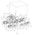
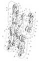
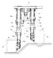
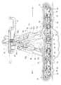
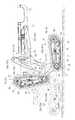
以下、本発明の実施の形態を、不整地用走行車両としての材木運搬車に適用した場合の図面について説明する。図1は材木運搬車の斜視図、図2は材木運搬車1の側面図、図3は同平面図、図4は後側走行部2a,2b及び前側走行部3a,3bの斜視図、図5は脚体5a,5bの側面図、図6は左右の脚体5a,5bを上方から視た斜視図、図7は左右の脚体5a,5bを下方から視た斜視図である。なお、以下の説明では、材木運搬車1の前進方向に向かって左側を単に左側と称し、同じく前進方向に向かって右側を単に右側と称する。  DETAILED DESCRIPTION OF THE PREFERRED EMBODIMENTS Hereinafter, drawings when an embodiment of the present invention is applied to a timber transport vehicle as a rough terrain vehicle will be described. 1 is a perspective view of a timber transporter, FIG. 2 is a side view of thetimber transporter 1, FIG. 3 is a plan view thereof, and FIG. 4 is a perspective view ofrear travel units 2a and 2b andfront travel units 3a and 3b. 5 is a side view of thelegs 5a and 5b, FIG. 6 is a perspective view of the left andright legs 5a and 5b as viewed from above, and FIG. 7 is a perspective view of the left andright legs 5a and 5b as viewed from below. In the following description, the left side in the forward direction of thetimber transport vehicle 1 is simply referred to as the left side, and the right side in the forward direction is also simply referred to as the right side.

図1乃至図3に示されるように、材木運搬車1は、左右の後側走行部2a,2bと、左右の前側走行部3a,3bと、後述する駆動源としてのエンジン20、油圧機器21、及び作業機としての丸太握持アーム22等を配置する作業機体4と、後側走行部2a,2b及び前側走行部3a,3bに作業機体4を支持する左右の脚体5a,5bとを備えている。  As shown in FIGS. 1 to 3, thetimber transport vehicle 1 includes a left and rightrear traveling units 2 a and 2 b, left and rightfront traveling units 3 a and 3 b, anengine 20 as a drive source described later, and ahydraulic device 21. , And awork machine body 4 in which alog gripping arm 22 or the like as a work machine is arranged, and left andright legs 5a and 5b that support thework machine body 4 on therear traveling units 2a and 2b and thefront traveling units 3a and 3b. I have.

図2に示されるように、作業機体4には、オペレータが搭乗する運転キャビン23と、丸太扼持アーム22によって丸太24を載せる荷台25とを備える。運転キャビン23は、オペレータが座乗する操縦座席26と、左の前側走行部2a及び後側走行部3aと右の前側走行部2b及び後側走行部3bとを差動させて進路を変更操作(舵取り)する操縦ハンドル27と、左右の後側走行部2a,2b及び左右の前側走行部3a,3bの駆動速度の変更(車速の変速)と回転方向の変更(前進と後進の切換)とを操作する走行変速レバー28と、左右の後側走行部2a,2b又は左右の前側走行部3a,3bを制動操作するブレーキペダル29とを有する。また、運転キャビン23内の設置台98に遠隔操縦器99を取外し可能に配置する。材木運搬車1は、主として遠隔操縦器99によって操縦して、材木の積み下ろし及び運搬等の作業を実行するが、オペレータが操縦座席26に座乗して材木を積み下ろしたり運搬できるように構成している。  As shown in FIG. 2, thework machine body 4 includes anoperation cabin 23 on which an operator gets on, and aloading platform 25 on which alog 24 is placed by alog holding arm 22. The drivingcabin 23 is configured to change the course by making thecontrol seat 26 on which the operator sits, the leftfront traveling unit 2a and therear traveling unit 3a, the rightfront traveling unit 2b and therear traveling unit 3b differential. (Steering) thesteering handle 27, the driving speed of the left and rightrear traveling units 2a, 2b and the left and right front travelingunits 3a, 3b (change in vehicle speed) and the rotation direction (switching between forward and reverse) And abrake pedal 29 for braking the left and right rear runningportions 2a and 2b or the left and right front runningportions 3a and 3b. Further, theremote controller 99 is detachably disposed on the installation table 98 in theoperation cabin 23. Thetimber transport vehicle 1 is mainly operated by theremote controller 99 to perform operations such as loading and unloading of timber, but the operator can sit on thecontrol seat 26 to load and unload timber. Yes.

図3及び図4に示されるように、左右の後側走行部2a,2b及び左右の前側走行部3a,3bは、複数のトラックローラ30を軸支したトラックフレーム31と、トラックフレーム31に回動可能に配置した駆動スプロケット32と、トラックフレーム31にテンション調節機構33を介して配置したテンションローラ34と、駆動スプロケット32を駆動する走行駆動油圧モータ35と、合成ゴム製の履帯形状の走行クローラ36とを有する。駆動スプロケット32と、テンションローラ34と、複数のトラックローラ30とを介して、トラックフレーム31に走行クローラ36を支持している。走行駆動油圧モータ35によって走行クローラ36が前進方向又は後進方向に駆動されることになる。  As shown in FIGS. 3 and 4, the left and rightrear running units 2 a and 2 b and the left and rightfront running units 3 a and 3 b rotate around thetrack frame 31 and atrack frame 31 that supports a plurality oftrack rollers 30. Adrive sprocket 32 movably disposed, atension roller 34 disposed on thetrack frame 31 via atension adjusting mechanism 33, a travel drivehydraulic motor 35 for driving thedrive sprocket 32, and a crawler-shaped travel crawler made ofsynthetic rubber 36. Atravel crawler 36 is supported on thetrack frame 31 via adrive sprocket 32,tension rollers 34, and a plurality oftrack rollers 30. Thetravel crawler 36 is driven in the forward direction or the reverse direction by the travel drivehydraulic motor 35.

図5乃至図7に示されるように、左右の脚体5a,5bは、第1乃至第10の複数の軸によって、個別に折り曲げてそれぞれの姿勢を変更可能に構成している。即ち、第1軸及び第2軸として後述する左右の股関節軸7と、第3軸及び第4軸として後述する左右の膝関節軸6と、第5軸及び第6軸として後述する左右の足首関節軸5と、第7軸及び第8軸として後述する左右の後側足関節軸10と、第9軸及び第10軸として後述する左右の前側足関節軸11とを備えている。  As shown in FIGS. 5 to 7, the left andright legs 5 a and 5 b are configured to be individually bent by a plurality of first to tenth shafts to change their postures. That is, left and right hipjoint shafts 7 described later as first and second axes, left and right kneejoint shafts 6 described later as third and fourth axes, and left and right ankles described later as fifth and sixth axes. It includes ajoint shaft 5, left and right rearfoot joint shafts 10 to be described later as seventh and eighth axes, and left and right frontfoot joint shafts 11 to be described later as ninth and tenth axes.

図5乃至図7に示されるように、左右の脚体5a,5bは、それぞれ水平方向(横方向)に延びる足首関節軸5と、膝関節軸6と、股関節軸7とを有する。左右の脚体5a,5bに足首関節軸5を介して左右の後側走行部2a,2b及び左右の前側走行部3a,3bを連結する。左右の脚体5a,5bに股関節軸7を介して作業機体4を連結する。膝関節軸6を介して左右の脚体5a,5bが側面視でく形状に折り曲がるように構成している。  As shown in FIGS. 5 to 7, the left andright legs 5 a and 5 b each have anankle joint shaft 5, aknee joint shaft 6, and ahip joint shaft 7 extending in the horizontal direction (lateral direction). The left and right rear runningportions 2a and 2b and the left and right front runningportions 3a and 3b are connected to the left andright legs 5a and 5b via the anklejoint shaft 5, respectively. Thework machine body 4 is connected to the left andright legs 5a, 5b via thehip joint shaft 7. The left andright legs 5a and 5b are configured to be bent in a side view through theknee joint shaft 6.

図5乃至図7に示されるように、左右の脚体5a,5bは、第1乃至第10の複数のフレームによって、個別に折り曲げてそれぞれの姿勢を変更可能に構成している。即ち、第1フレーム及び第2フレームとして後述する左右の後側足フレーム8a,8bと、第3フレーム及び第4フレームとして後述する左右の前側足フレーム9a,9bと、第5フレーム及び第6フレームとして後述する左右の足根フレーム12a,12bと、第7フレーム及び第8フレームとして後述する左右の脛フレーム13a,13bと、第9フレーム及び第10フレームとして後述する左右の大腿フレーム14a,14bとを備えている。  As shown in FIGS. 5 to 7, the left andright legs 5 a and 5 b are configured to be individually bent by a plurality of first to tenth frames and change their postures. That is, left and rightrear foot frames 8a and 8b, which will be described later as first and second frames, left and rightfront foot frames 9a and 9b, which will be described later as third and fourth frames, and fifth and sixth frames. Left andright foot frames 12a and 12b, which will be described later, left andright shin frames 13a and 13b which will be described later as seventh and eighth frames, and left andright thigh frames 14a and 14b which will be described later as ninth and tenth frames, respectively. It has.

図5乃至図7に示されるように、左右の脚体5a,5bは、左右の後側走行部2a,2bを支持する左右の後側足フレーム8a,8bと、左右の前側走行部3a,3bを支持する左右の前側足フレーム9a,9bと、左右の後側足フレーム8a,8bの前端側(左右の前側足フレーム9a,9bの後端側)に左右の後側足関節軸10(前側足関節軸11)を介して後端側(前端側)を連結する左右の足根フレーム12a,12bと、左右の足根フレーム12a,12bの前後幅の中間の上端側に左右の足首関節軸5を介して下端側を連結する左右の脛フレーム13a,13bと、左右の脛フレーム13a,13bの上端側に左右の膝関節軸6を介して下端側を連結する左右の大腿フレーム14a,14bとを有している。左右の脚体5a,5bは、左右対称の構造に構成されている。  As shown in FIGS. 5 to 7, the left andright legs 5 a and 5 b include left and rightrear foot frames 8 a and 8 b that support the left and right rear runningportions 2 a and 2 b, and left and right front runningportions 3 a and Left and rightfront foot frames 9a and 9b that support 3b, and left and right rear foot joint shafts 10 (on the rear end sides of the left and rightfront foot frames 9a and 9b) on the front end sides of the left and rightrear foot frames 8a and 8b. The left andright foot frames 12a and 12b that connect the rear end side (front end side) via the front foot joint shaft 11) and the left and right ankle joints at the upper end in the middle of the front and rear width of the left andright foot frames 12a and 12b Left and righttibial frames 13a, 13b connecting the lower end side via theshaft 5, and left andright thigh frames 14a connecting the lower end side via the left and rightknee joint shafts 6 to the upper end side of the left and righttibial frames 13a, 13b, 14b. The left andright legs 5a and 5b are configured in a symmetrical structure.

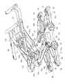
図5乃至図7に示されるように、作業機体4は坐フレーム15を有し、左右の脚体5a,5bの各大腿フレーム14a,14bの上下幅の中間に股関節軸7を介して坐フレーム15の前後幅の中間を連結している。股関節軸7回りに坐フレーム15が回動することによって、坐フレーム15の前端側(後端側)が上動(下動)又は下動(上動)し、坐フレーム15の前後方向の傾斜角が変更されることになる。  As shown in FIGS. 5 to 7, theworking machine body 4 has aseat frame 15, and the seat frame is interposed between the upper and lower widths of thethigh frames 14 a and 14 b of the left andright legs 5 a and 5 b via thehip joint shaft 7. The middle of 15 front and rear widths are connected. By rotating theseat frame 15 around the hipjoint axis 7, the front end side (rear end side) of theseat frame 15 moves upward (downward) or downward (upward), and theseat frame 15 tilts in the front-rear direction. The corner will be changed.

図5乃至図7に示されるように、左右の脚体5a,5bは、第1乃至第10の複数の油圧シリンダによって、個別に折り曲げてそれぞれの姿勢を変更可能に構成している。即ち、第1油圧シリンダ及び第2油圧シリンダとして後述する左右の股関節油圧シリンダ44a,44bと、第3油圧シリンダ及び第4油圧シリンダとして後述する左右の膝関節油圧シリンダ48a,48bと、第5油圧シリンダ及び第6油圧シリンダとして後述する左右の足首関節油圧シリンダ52a,52bと、第7油圧シリンダ及び第8油圧シリンダとして後述する左右のかかと関節油圧シリンダ56a,56bと、第9油圧シリンダ及び第10油圧シリンダとして後述する左右のつま先関節油圧シリンダ60a,60bとを備えている。  As shown in FIGS. 5 to 7, the left andright legs 5 a and 5 b are configured to be individually bent by a plurality of first to tenth hydraulic cylinders to change their postures. That is, left and right hip jointhydraulic cylinders 44a and 44b, which will be described later as first and second hydraulic cylinders, left and right knee jointhydraulic cylinders 48a and 48b, which will be described later as third and fourth hydraulic cylinders, and a fifth hydraulic pressure. Left and right ankle jointhydraulic cylinders 52a and 52b, which will be described later as cylinders and sixth hydraulic cylinders, left and right heel jointhydraulic cylinders 56a and 56b, which will be described later as seventh hydraulic cylinders and eighth hydraulic cylinders, ninth hydraulic cylinders and tenth hydraulic cylinders Left and right toe jointhydraulic cylinders 60a and 60b, which will be described later, are provided as hydraulic cylinders.

股関節軸7に側面視L形状の中間を回動可能に被嵌したピッチアーム40と、坐フレーム15の前後方向の傾斜角を調節するための水平機構としてのピッチ油圧シリンダ16とを備える。坐フレーム15の前端側に軸体41を介してピッチ油圧シリンダ16を連結する。ピッチ油圧シリンダ16のピストン16aの先端側に軸体42を介してピッチアーム40のL形状の一端側を連結する。また、左右の大腿フレーム14a,14bの下端側に軸体43を介して左右の股関節油圧シリンダ44a,44bを連結する。股関節油圧シリンダ44a,44bのピストン45の先端側に軸体46を介してピッチアーム40のL形状の他端側を連結する。  Apitch arm 40 that is fitted to the hipjoint shaft 7 so as to be rotatable in the middle of the L shape in a side view and a pitchhydraulic cylinder 16 as a horizontal mechanism for adjusting the tilt angle in the front-rear direction of theseat frame 15 are provided. A pitchhydraulic cylinder 16 is connected to the front end side of theseat frame 15 via ashaft body 41. The L-shaped one end side of thepitch arm 40 is connected to the tip end side of thepiston 16 a of the pitchhydraulic cylinder 16 via theshaft body 42. In addition, left and right hip jointhydraulic cylinders 44a and 44b are connected to the lower ends of the left and right thigh frames 14a and 14b via ashaft body 43. The other end side of the L-shape of thepitch arm 40 is connected to the tip end side of thepiston 45 of the hip jointhydraulic cylinders 44 a and 44 b via theshaft body 46.

その結果、ピッチ油圧シリンダ16によって股関節軸7回りに坐フレーム15を回動して、坐フレーム15の前後方向の傾斜を修正して前後方向に水平に支持することになる。また、左右の股関節油圧シリンダ44a,44bによって股関節軸7回りに坐フレーム15が回動して、坐フレーム15と左右の大腿フレーム14a,14bとの相対的な連結角度を変更することになる。  As a result, theseat frame 15 is rotated around the hipjoint axis 7 by the pitchhydraulic cylinder 16, and the tilt of theseat frame 15 in the front-rear direction is corrected and horizontally supported in the front-rear direction. Further, theseat frame 15 is rotated around the hipjoint axis 7 by the left and right hip jointhydraulic cylinders 44a and 44b, and the relative connection angle between theseat frame 15 and the left and right thigh frames 14a and 14b is changed.

即ち、左右の股関節油圧シリンダ44a,44bを作動させながら、ピッチ油圧シリンダ16を作動させることによって、坐フレーム15の前後方向の傾斜が略水平に維持された状態で、坐フレーム15と左右の大腿フレーム14a,14bとの相対角度が変更されることになる。なお、左右の股関節油圧シリンダ44a,44bを各別に作動することによって、坐フレーム15に対する左右の大腿フレーム14a,14bの相対角度は独立してそれぞれ変更される。  That is, by operating the pitchhydraulic cylinder 16 while operating the left and right hip jointhydraulic cylinders 44a, 44b, theseat frame 15 and the left and right thighs are maintained in a state where the tilt in the front-rear direction of theseat frame 15 is maintained substantially horizontal. The relative angle with theframes 14a and 14b is changed. By operating the left and right hip jointhydraulic cylinders 44a and 44b separately, the relative angles of the left and right thigh frames 14a and 14b with respect to theseat frame 15 are independently changed.

左右の大腿フレーム14a,14bの上端側には、左右の軸体47を介して、左右の膝関節油圧シリンダ48a,48bをそれぞれ連結する。左右の膝関節油圧シリンダ48a,48bのピストン49の先端側には、左右の軸体50を介して、脛フレーム13a,13bの中間をそれぞれ連結する。その結果、左右の膝関節油圧シリンダ48a,48bを作動することによって、左右の膝関節軸6回りに左右の大腿フレーム14a,14bが回動して、左右の脛フレーム13a,13bと左右の大腿フレーム14a,14bとの相対的な連結角度がそれぞれ変更されることになる。なお、左右の膝関節油圧シリンダ48a,48bを各別に作動することによって、左右の脛フレーム13a,13bに対する左右の大腿フレーム14a,14bの相対角度は独立してそれぞれ変更される。  Left and right knee jointhydraulic cylinders 48a and 48b are connected to upper end sides of the left and right thigh frames 14a and 14b via left andright shaft bodies 47, respectively. Intermediate portions of the shin frames 13a and 13b are connected to the distal end sides of thepistons 49 of the left and right knee jointhydraulic cylinders 48a and 48b via left andright shaft bodies 50, respectively. As a result, by operating the left and right knee jointhydraulic cylinders 48a and 48b, the left and right thigh frames 14a and 14b rotate around the left and right kneejoint axes 6, and the left and right tibial frames 13a and 13b and the left and right thigh frames are rotated. The relative connection angles with theframes 14a and 14b are respectively changed. By operating the left and right knee jointhydraulic cylinders 48a and 48b separately, the relative angles of the left and right thigh frames 14a and 14b with respect to the left and right tibial frames 13a and 13b are independently changed.

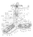
左右の脛フレーム13a,13bの上端側には、左右の軸体51を介して、左右の足首関節油圧シリンダ52a,52bをそれぞれ連結する。左右の足首関節油圧シリンダ52a,52bのピストン53の先端側には、左右の軸体54を介して、左右の足根フレーム12a,12bの前端側をそれぞれ連結する。その結果、左右の足首関節油圧シリンダ52a,52bを作動することによって、左右の足首関節軸5回りに左右の脛フレーム13a,13bが回動して、左右の足根フレーム12a,12bと左右の脛フレーム13a,13bとの相対的な連結角度がそれぞれ変更されることになる。なお、左右の足首関節油圧シリンダ52a,52bを各別に作動することによって、左右の足根フレーム12a,12bに対する左右の脛フレーム13a,13bの相対角度は独立してそれぞれ変更される。  Left and right ankle jointhydraulic cylinders 52a and 52b are connected to upper end sides of the left and right shin frames 13a and 13b via left andright shaft bodies 51, respectively. The front end sides of the left and right foot frames 12a and 12b are connected to the distal end sides of thepistons 53 of the left and right ankle jointhydraulic cylinders 52a and 52b via left andright shaft bodies 54, respectively. As a result, by operating the left and right ankle jointhydraulic cylinders 52a and 52b, the left and right tibial frames 13a and 13b rotate around the left and right anklejoint axes 5, and the left and right foot frames 12a and 12b The relative connection angles with the shin frames 13a and 13b are respectively changed. By operating the left and right ankle jointhydraulic cylinders 52a and 52b separately, the relative angles of the left and right shin frames 13a and 13b with respect to the left and right foot frames 12a and 12b are independently changed.

左右の足根フレーム12a,12bの後端側には、左右の軸体55を介して、左右のかかと関節油圧シリンダ56a,56bをそれぞれ連結する。左右のかかと関節油圧シリンダ56a,56bのピストン57の先端側には、左右の軸体58を介して、左右の後側足フレーム8a,8bの後端側をそれぞれ連結する。その結果、左右のかかと関節油圧シリンダ56a,56bを作動することによって、左右の後側足関節軸10回りに左右の後側足フレーム8a,8bが回動して、左右の後側足フレーム8a,8bと左右の足根フレーム12a,12bとの相対的な連結角度がそれぞれ変更されることになる。なお、左右のかかと関節油圧シリンダ56a,56bを各別に作動することによって、左右の足根フレーム12a,12bに対する左右の後側足フレーム8a,8bの相対角度は独立してそれぞれ変更される。  Left and right heel jointhydraulic cylinders 56a and 56b are connected to the rear end sides of the left and right foot frames 12a and 12b via left andright shaft bodies 55, respectively. The left and right rear foot frames 8a and 8b are connected to the front ends of thepistons 57 of the left and right heel jointhydraulic cylinders 56a and 56b via left andright shaft bodies 58, respectively. As a result, by operating the left and right heel jointhydraulic cylinders 56a and 56b, the left and right rear foot frames 8a and 8b rotate around the left and right rear footjoint shafts 10, and the left and rightrear foot frames 8a. , 8b and the right and leftfoot frames 12a, 12b are respectively changed in relative connection angle. By operating the left and right heel jointhydraulic cylinders 56a and 56b separately, the relative angles of the left and right rear foot frames 8a and 8b with respect to the left and right foot frames 12a and 12b are independently changed.

左右の足根フレーム12a,12bの前端側には、左右の軸体59を介して、左右のつま先関節油圧シリンダ60a,60bをそれぞれ連結する。左右のつま先関節油圧シリンダ60a,60bのピストン61の先端側には、左右の軸体62を介して、左右の前側足フレーム9a,9bの前端側をそれぞれ連結する。その結果、左右のつま先関節油圧シリンダ60a,60bを作動することによって、左右の前側足関節軸11回りに左右の前側足フレーム9a,9bが回動して、左右の前側足フレーム9a,9bと左右の足根フレーム12a,12bとの相対的な連結角度がそれぞれ変更されることになる。なお、左右のつま先関節油圧シリンダ60a,60bを各別に作動することによって、左右の足根フレーム12a,12bに対する左右の前側足フレーム9a,9bの相対角度は独立してそれぞれ変更される。  Left and right toe jointhydraulic cylinders 60a and 60b are connected to the front end sides of the left and right foot frames 12a and 12b via left andright shaft bodies 59, respectively. The front end sides of the left and right front foot frames 9a and 9b are connected to the distal ends of thepistons 61 of the left and right toe jointhydraulic cylinders 60a and 60b via the left andright shaft bodies 62, respectively. As a result, by operating the left and right toe jointhydraulic cylinders 60a and 60b, the left and right front foot frames 9a and 9b rotate around the left and right front footjoint shafts 11, and the left and right front foot frames 9a and 9b The relative connection angles with the left and right foot frames 12a and 12b are respectively changed. By operating the left and right toe jointhydraulic cylinders 60a and 60b separately, the relative angles of the left and right front foot frames 9a and 9b with respect to the left andright foot frame 12a and 12b are independently changed.

図8は本実施形態における材木運搬車1(不整地用走行車両)の油圧回路70を示している。材木運搬車1の油圧回路70は、左右の後側走行部2a,2b及び左右の前側走行部3a,3bの出力可変容量形の各走行駆動油圧モータ35をそれぞれ駆動する走行用油圧ポンプ71と、油圧機器21の各部にチャージ圧油を供給するチャージ用油圧ポンプ72と、左の脚体5aの各油圧シリンダ44a,48a,52a,56a,60aを作動する出力可変容量形の右側脚体用油圧ポンプ73と、右の脚体5bの各油圧シリンダ44b,48b,52b,56b,60bを作動する出力可変容量形の左側脚体用油圧ポンプ74とを備える。走行用油圧ポンプ71と、チャージ用油圧ポンプ72と、右側脚体用油圧ポンプ73と、左側脚体用油圧ポンプ74とは、エンジン20の回転力により作動する。なお、油圧回路70には、リリーフ弁や流量調整弁、チェック弁、オイルクーラ、オイルフィルタ等を備えている。  FIG. 8 shows ahydraulic circuit 70 of the timber transport vehicle 1 (a rough terrain vehicle) according to this embodiment. Thehydraulic circuit 70 of thetimber transport vehicle 1 includes a travelinghydraulic pump 71 that drives each of the left and rightrear traveling units 2a and 2b and the left and rightfront traveling units 3a and 3b. For the right leg of the output variable capacity type that operates thehydraulic cylinders 44a, 48a, 52a, 56a, 60a of theleft leg 5a and the chargehydraulic pump 72 for supplying the charge pressure oil to each part of thehydraulic equipment 21 Thehydraulic pump 73 and an output variable displacement left leghydraulic pump 74 that operates thehydraulic cylinders 44b, 48b, 52b, 56b, 60b of theright leg 5b are provided. The travelinghydraulic pump 71, the charginghydraulic pump 72, the right leghydraulic pump 73, and the left leghydraulic pump 74 are operated by the rotational force of theengine 20. Thehydraulic circuit 70 includes a relief valve, a flow rate adjustment valve, a check valve, an oil cooler, an oil filter, and the like.

また、右側脚体用油圧ポンプ73には、分流弁75aと、右の股関節制御弁76aとを介して右の股関節油圧シリンダ44aを接続している。右側脚体用油圧ポンプ73には、分流弁77aと、右の膝関節制御弁78aとを介して右の膝関節油圧シリンダ48aを接続している。右側脚体用油圧ポンプ73には、分流弁79aと、右の足首関節制御弁80aとを介して右の足首関節油圧シリンダ52aを接続している。右側脚体用油圧ポンプ73には、分流弁81aと、右のつま先関節制御弁82aとを介して右のつま先関節油圧シリンダ56aを接続している。右側脚体用油圧ポンプ73には、分流弁83aと、右のかかと関節制御弁84aとを介して右のかかと関節油圧シリンダ60aを接続している。右側脚体用油圧ポンプ73には、分流弁85と、ピッチ制御弁86(電磁比例油圧制御弁)とを介してピッチ油圧シリンダ16を接続している。  The right leghydraulic pump 73 is connected to the right hip jointhydraulic cylinder 44a via adiversion valve 75a and a right hipjoint control valve 76a. A right knee jointhydraulic cylinder 48a is connected to the right leghydraulic pump 73 via adiversion valve 77a and a right kneejoint control valve 78a. A right ankle jointhydraulic cylinder 52a is connected to the right leghydraulic pump 73 via adiversion valve 79a and a right anklejoint control valve 80a. A right toe jointhydraulic cylinder 56a is connected to the right leghydraulic pump 73 via adiversion valve 81a and a right toejoint control valve 82a. A right heel jointhydraulic cylinder 60a is connected to the right leghydraulic pump 73 via adiversion valve 83a and a right heeljoint control valve 84a. The pitchhydraulic cylinder 16 is connected to the right leghydraulic pump 73 via aflow dividing valve 85 and a pitch control valve 86 (electromagnetic proportional hydraulic control valve).

また、上述した右側脚体用油圧ポンプ73と同様に、左側脚体用油圧ポンプ74には、分流弁75bと、左の股関節制御弁76bとを介して左の股関節油圧シリンダ44bを接続している。右側脚体用油圧ポンプ73には、分流弁77bと、左の膝関節制御弁78bとを介して左の膝関節油圧シリンダ48bを接続している。右側脚体用油圧ポンプ73には、分流弁79bと、左の足首関節制御弁80bとを介して左の足首関節油圧シリンダ52bを接続している。右側脚体用油圧ポンプ73には、分流弁81bと、左のつま先関節制御弁82bとを介して左のつま先関節油圧シリンダ56bを接続している。右側脚体用油圧ポンプ73には、分流弁83bと、左のかかと関節制御弁84bとを介して左のかかと関節油圧シリンダ60bを接続している。  Similarly to the right leghydraulic pump 73 described above, the left leghydraulic pump 74 is connected to the left hip jointhydraulic cylinder 44b via the diversion valve 75b and the left hipjoint control valve 76b. Yes. A left knee jointhydraulic cylinder 48b is connected to the right leghydraulic pump 73 via a diversion valve 77b and a left kneejoint control valve 78b. The left ankle jointhydraulic cylinder 52b is connected to the right leghydraulic pump 73 via adiversion valve 79b and a left anklejoint control valve 80b. A left toe jointhydraulic cylinder 56b is connected to the right leghydraulic pump 73 via adiversion valve 81b and a left toejoint control valve 82b. A left heel jointhydraulic cylinder 60b is connected to the right leghydraulic pump 73 via adiversion valve 83b and a left heeljoint control valve 84b.

上述した各油圧シリンダ44a,48a,52a,56a,60a,44b,48b,52b,56b,60bには、それらの作動油圧をそれぞれ検出する油圧センサ87を取付けている。なお、上述した各制御弁76a,78a,80a,82a,84a,76b,78b,80b,82b,84bは、電磁式方向流量制御油圧切換弁にて形成し、位置制御及び力制御(インピーダンス制御)によって、各油圧シリンダに供給する作動油の印加方向及び印加流量を制御可能に構成している。  Each of thehydraulic cylinders 44a, 48a, 52a, 56a, 60a, 44b, 48b, 52b, 56b, and 60b is provided with ahydraulic sensor 87 that detects their hydraulic pressures. Thecontrol valves 76a, 78a, 80a, 82a, 84a, 76b, 78b, 80b, 82b, 84b described above are formed by electromagnetic directional flow control hydraulic switching valves, and position control and force control (impedance control). Thus, the application direction and flow rate of the hydraulic oil supplied to each hydraulic cylinder can be controlled.

さらに走行用油圧ポンプ71には、左前変速制御弁88aを介して左前走行駆動油圧モータ35を接続する。左前走行駆動油圧モータ35の出力(回転速度)を変更する操向油圧シリンダ89を備える。左前変速制御弁88aに操向制御弁90aを介して操向油圧シリンダ89を接続している。走行用油圧ポンプ71には、右前変速制御弁88bを介して右前走行駆動油圧モータ35を接続する。右前走行駆動油圧モータ35の出力(回転速度)を変更する操向油圧シリンダ89を備える。右前変速制御弁88bに操向制御弁90bを介して操向油圧シリンダ89を接続している。  Further, the left front travel drivehydraulic motor 35 is connected to the travelhydraulic pump 71 via a left frontshift control valve 88a. A steeringhydraulic cylinder 89 that changes the output (rotational speed) of the left front travel drivehydraulic motor 35 is provided. A steeringhydraulic cylinder 89 is connected to the left frontshift control valve 88a via asteering control valve 90a. A right front travel drivehydraulic motor 35 is connected to the travelhydraulic pump 71 via a right frontshift control valve 88b. A steeringhydraulic cylinder 89 that changes the output (rotational speed) of the right front travel drivehydraulic motor 35 is provided. A steeringhydraulic cylinder 89 is connected to the right frontshift control valve 88b via asteering control valve 90b.

また、走行用油圧ポンプ71には、左後変速制御弁88cを介して左後走行駆動油圧モータ35を接続する。左後走行駆動油圧モータ35の出力(回転速度)を変更する操向油圧シリンダ89を備える。左後変速制御弁88cに操向制御弁90cを介して操向油圧シリンダ89を接続している。走行用油圧ポンプ71には、右後変速制御弁88dを介して右後走行駆動油圧モータ35を接続する。右後走行駆動油圧モータ35の出力(回転速度)を変更する操向油圧シリンダ89を備える。右後変速制御弁88dに操向制御弁90dを介して操向油圧シリンダ89を接続している。各走行駆動油圧モータ35の出力軸の回転速度を検出する左前車速センサ91、右前車速センサ91、左後車速センサ91、右後車速センサ91を備える。  Further, the left rear travel drivehydraulic motor 35 is connected to the travelhydraulic pump 71 via the left rearshift control valve 88c. A steeringhydraulic cylinder 89 that changes the output (rotational speed) of the left rear traveling drivehydraulic motor 35 is provided. A steeringhydraulic cylinder 89 is connected to the left rearshift control valve 88c via asteering control valve 90c. A right rear traveling drivehydraulic motor 35 is connected to the travelinghydraulic pump 71 via a right rearshift control valve 88d. A steeringhydraulic cylinder 89 that changes the output (rotational speed) of the right rear traveling drivehydraulic motor 35 is provided. A steeringhydraulic cylinder 89 is connected to the right rearshift control valve 88d via asteering control valve 90d. A left frontvehicle speed sensor 91, a right frontvehicle speed sensor 91, a left rearvehicle speed sensor 91, and a right rearvehicle speed sensor 91 that detect the rotational speed of the output shaft of each travel drivehydraulic motor 35 are provided.

次に、本実施形態の材木運搬車1の走行制御について説明する。図9は、材木運搬車1の走行制御手段の機能ブロック図であり、マイクロコンピュータ等の走行コントローラ100は、制御プログラムを記憶したROMと各種データを記憶したRAMとを備える。図9に示されるように、走行コントローラ100の入力側には、坐フレーム15の左右方向の傾斜角を検出するロールセンサ101と、坐フレーム15の左右方向の傾斜角速度を検出するロール角速度センサ102と、坐フレーム15の前後方向の傾斜角を検出するピッチセンサ103と、右側脚体5aの縮小(坐フレーム15の右側の下動)リミット位置を検出する左下限センサ104と、左側脚体5bの縮小(坐フレーム15の左側の下動)リミット位置を検出する右下限センサ105と、上述した各油圧センサ87と、オペレータが操作する操縦ハンドル27の切り角(左旋回操作量及び右旋回操作量)を検出する操舵角センサ106と、走行変速レバー28の操作位置(前進操作位置及び後進操作位置)を検出する走行変速センサ107と、上述した各車速センサ91とを接続している。また、操舵角センサ106と、走行変速センサ107とは、遠隔操縦器99からの無線操縦信号を受信するように構成している。  Next, traveling control of thetimber transport vehicle 1 of the present embodiment will be described. FIG. 9 is a functional block diagram of the travel control means of thetimber transport vehicle 1. Thetravel controller 100 such as a microcomputer includes a ROM storing a control program and a RAM storing various data. As shown in FIG. 9, on the input side of thetravel controller 100, aroll sensor 101 that detects the horizontal tilt angle of theseat frame 15 and a rollangular velocity sensor 102 that detects the horizontal tilt angular velocity of theseat frame 15. Apitch sensor 103 that detects the tilt angle of theseat frame 15 in the front-rear direction, a leftlower limit sensor 104 that detects a limit position for reducing theright leg 5a (downward movement on the right side of the seat frame 15), and aleft leg 5b. Reduction (downward movement of the left side of the seat frame 15), a lowerright limit sensor 105 for detecting a limit position, thehydraulic sensors 87 described above, and a turning angle of the steering handle 27 operated by the operator (a left turn operation amount and a right turn). Asteering angle sensor 106 for detecting the operation amount), and atravel shift sensor 1 for detecting the operation position (forward operation position and reverse operation position) of thetravel shift lever 28. 7, are connected with eachvehicle speed sensor 91 described above. In addition, thesteering angle sensor 106 and the travelingspeed change sensor 107 are configured to receive a radio control signal from theremote controller 99.

また、図9に示されるように、走行コントローラ100の出力側には、上述した左右の脚体5a,5bの姿勢を制御する各制御弁76a,78a,80a,82a,84a,76b,78b,80b,82b,84bと、坐フレーム15の前後傾きを制御するピッチ制御弁86と、上述した左右の後側走行部2a,2b及び左右の前側走行部3a,3bの各走行駆動油圧モータ35を制御する各制御弁88a,88b,88c,88d,90a,90b,90c,90dとを接続している。  Further, as shown in FIG. 9, on the output side of thetravel controller 100, thecontrol valves 76a, 78a, 80a, 82a, 84a, 76b, 78b for controlling the postures of the left andright legs 5a, 5b described above are provided. 80b, 82b, 84b, apitch control valve 86 for controlling the forward / backward inclination of theseat frame 15, and the above-described travel drivehydraulic motors 35 for the left and rightrear travel units 2a, 2b and the left and rightfront travel units 3a, 3b. Thecontrol valves 88a, 88b, 88c, 88d, 90a, 90b, 90c, 90d to be controlled are connected.

上記の構成により、材木運搬車1が前進方向又は後進方向に移動している場合、ロール角速度センサ102の検出結果に基づき、各制御弁76a,78a,80a,82a,84a,76b,78b,80b,82b,84bが作動して、左下限センサ104及び右下限センサ105によって制限される高さ以上で、左右の脚体5a,5bを各別に伸縮させるための制御を開始する。ロールセンサ101の検出結果に基づき、各制御弁76a,78a,80a,82a,84a,76b,78b,80b,82b,84bの作動を中止して、坐フレーム15の左右方向の傾斜を修正する。また、ピッチセンサ103の検出結果に基づき、ピッチ制御弁86を作動して、坐フレーム15の前後方向の傾斜を修正する。  With the above configuration, when thetimber transport vehicle 1 is moving in the forward or reverse direction, thecontrol valves 76a, 78a, 80a, 82a, 84a, 76b, 78b, and 80b are based on the detection results of the rollangular velocity sensor 102. , 82b, 84b are activated, and control for expanding and contracting the left andright legs 5a, 5b separately is started at a height that is not less than the height limited by the leftlower limit sensor 104 and the rightlower limit sensor 105. Based on the detection result of theroll sensor 101, the operation of eachcontrol valve 76a, 78a, 80a, 82a, 84a, 76b, 78b, 80b, 82b, 84b is stopped, and the horizontal inclination of theseat frame 15 is corrected. Further, based on the detection result of thepitch sensor 103, thepitch control valve 86 is operated to correct the inclination of theseat frame 15 in the front-rear direction.

その結果、坐フレーム15は、左右の脚体5a,5bを介して略水平に保持される。また、左右の脚体5a,5b(坐フレーム15)を水平制御中、油圧センサ87の検出結果に基づき、各油圧シリンダ44a,48a,52a,56a,60a,44b,48b,52b,56b,60bの駆動速度を制御して、走行部2a,2b,3a,3bから左右の脚体5a,5bに伝達される路面からの衝撃力を吸収する。走行部2a,2b,3a,3bからの衝撃力が、坐フレーム15に伝わるのを防止できる。  As a result, theseat frame 15 is held substantially horizontally via the left andright legs 5a and 5b. Further, during horizontal control of the left andright legs 5a, 5b (seat frame 15), based on the detection result of thehydraulic sensor 87, eachhydraulic cylinder 44a, 48a, 52a, 56a, 60a, 44b, 48b, 52b, 56b, 60b. Is controlled to absorb the impact force from the road surface transmitted from the runningportions 2a, 2b, 3a, 3b to the left andright legs 5a, 5b. It is possible to prevent the impact force from the travelingparts 2a, 2b, 3a, 3b from being transmitted to theseat frame 15.

また、材木運搬車1外でオペレータが遠隔操縦器99を操作したり、材木運搬車1にオペレータが搭乗して操縦ハンドル27又は走行変速レバー28を操作することによって、材木運搬車1が前進方向又は後進方向に移動している場合、オペレータによって遠隔操縦器99又は操縦ハンドル27又は走行変速レバー28が操作されることによって、操舵角センサ106又は走行変速センサ107の検出結果に基づき、各制御弁88a,88b,88c,88d又は各制御弁90a,90b,90c,90dが作動して、各走行駆動油圧モータ35の駆動油圧又は出力回転速度を制御する。その結果、左右の後側走行部2a,2bの各走行クローラ36及び左右の前側走行部3a,3bの各走行クローラ36が各別に駆動制御され、前進移動又は後進移動又はUターン又はスピンターン(信地旋回)等が実行され、オペレータが希望する方向に希望する速度で移動できる。  In addition, when the operator operates theremote controller 99 outside thetimber transport vehicle 1 or the operator gets on thetimber transport vehicle 1 and operates the steering handle 27 or thetravel shift lever 28, thetimber transport vehicle 1 moves forward. Alternatively, when the vehicle is moving in the reverse direction, each control valve is operated based on the detection result of thesteering angle sensor 106 or the travelingshift sensor 107 by operating theremote controller 99, thesteering handle 27, or the travelingshift lever 28 by the operator. 88a, 88b, 88c, 88d or thecontrol valves 90a, 90b, 90c, 90d are operated to control the drive hydraulic pressure or the output rotational speed of each travel drivehydraulic motor 35. As a result, the traveling crawlers 36 of the left and rightrear traveling units 2a, 2b and the traveling crawlers 36 of the left and rightfront traveling units 3a, 3b are driven and controlled separately to move forward, reverse, U-turn or spin-turn ( And the like, and the operator can move in a desired direction at a desired speed.

次いで、図10乃至図15を参照して、左右の脚体5a,5bの折れ曲り作動を説明する。図10に示されるように、左右の脛フレーム13a,13bの上端側を前方に移動しながら、大腿フレーム14a,14bを機体前方に向けて水平姿勢に移動することによって、坐フレーム15が最前方に移動する。即ち、機体重心が最前方に移動することになる。したがって、急斜面を登る前進走行や、急斜面を下る後進走行のときの機体姿勢が安定する。  Next, the bending operation of the left andright legs 5a and 5b will be described with reference to FIGS. As shown in FIG. 10, theseat frame 15 is moved forward by moving the thigh frames 14a and 14b toward the front of the machine body in a horizontal posture while moving the upper ends of the left and right shin frames 13a and 13b forward. Move to. That is, the center of gravity of the aircraft moves to the forefront. Accordingly, the aircraft posture is stabilized during forward traveling on a steep slope and reverse traveling on a steep slope.

図11に示されるように、左右の脛フレーム13a,13bの上端側を後方に移動しながら、左右の大腿フレーム14a,14bの上端側を後方に移動することによって、坐フレーム15が最後方に移動する。即ち、機体重心が最後方に移動することになる。したがって、急斜面を登る後進走行や、急斜面を下る前進走行のときの機体姿勢が安定する。  As shown in FIG. 11, by moving the upper end sides of the left and right thigh frames 14a and 14b rearward while moving the upper end sides of the left and right tibial frames 13a and 13b rearward, theseat frame 15 is moved rearward. Moving. In other words, the center of gravity of the aircraft moves to the end. Accordingly, the aircraft posture is stabilized when the vehicle is traveling backward on a steep slope or traveling forward on a steep slope.

図12に示されるように、左右の脛フレーム13a,13bを略直立した姿勢に移動しながら、左右の大腿フレーム14a,14bを略直立した姿勢に移動し、後側走行部2a,2bの後端側を下降させ、且つ前側走行部3a,3bの前端側を下降させて、足根フレーム12a,12bの対地高さを高くすることによって、坐フレーム15の対地高さが高くなる。即ち、脛フレーム13a,13bの連結長さと、大腿フレーム14a,14bの連結長さと、足根フレーム12a,12bの対地高さとを加算した高さに、坐フレーム15が上動することになる。したがって、高所作業に必要な坐フレーム15の支持高さ(脚体5a,5bの長さ)、又は坐フレーム15を水上に支持しながら水中を移動するのに必要な坐フレーム15の支持高さ(脚体5a,5bの長さ)等を簡単に確保できる。  As shown in FIG. 12, the left and right thigh frames 13a and 13b are moved to a substantially upright posture while the left and right thigh frames 14a and 14b are moved to a substantially upright posture, and therear running portions 2a and 2b are The ground height of theseat frame 15 is increased by lowering the end side and lowering the front end side of thefront running portions 3a and 3b to increase the ground height of the foot frames 12a and 12b. That is, theseat frame 15 moves up to a height obtained by adding the connection length of the shin frames 13a and 13b, the connection length of the thigh frames 14a and 14b, and the height of the foot frames 12a and 12b to the ground. Therefore, the support height of the seat frame 15 (the length of thelegs 5a and 5b) necessary for working at a high place, or the support height of theseat frame 15 required to move underwater while supporting theseat frame 15 on the water. The length (the length of thelegs 5a, 5b) can be easily secured.

図13に示されるように、前側走行部3a,3bの前端側を上昇させることによって、前側走行部3a,3bの走行クローラ36の迎え角より大きな路面の進行方向の段差を、前側走行部3a,3bが上り下り移動できる。また、図14に示されるように、後側走行部2a,2bの後端側を下降させることによって、後側走行部2a,2bの走行クローラ36の迎え角より大きな路面の進行方向の段差を、後側走行部2a,2bが上り下り移動できる。  As shown in FIG. 13, by raising the front end side of the front travelingunits 3a, 3b, a step in the traveling direction of the road surface that is larger than the angle of attack of the travelingcrawler 36 of the front travelingunits 3a, 3b is changed to the front travelingunit 3a. , 3b can move up and down. Further, as shown in FIG. 14, by lowering the rear end side of therear traveling units 2a and 2b, a step in the traveling direction of the road surface that is larger than the angle of attack of the travelingcrawler 36 of therear traveling units 2a and 2b. Therear traveling units 2a and 2b can move up and down.

図15に示されるように、右側の脚体5a(左側の脚体5b)を伸長(縮小)しながら、左側の脚体5b(右側の脚体5a)を縮小(伸長)することによって、右の前側走行部3a及び後側走行部2aを路面の左右方向の段差の低い方に移動させながら、左の前側走行部3b及び後側走行部2bを路面の左右方向の段差の高い方に移動させることができる。即ち、路面の左右方向の段差に追従させて、右の前側走行部3a及び後側走行部2a高さと、左の前側走行部3b及び後側走行部2bの高さとを段違いに異ならせて移動できる。したがって、路肩の土手を跨ぐ走行状態や、山の斜面を横切る走行状態のときに、安定した機体姿勢を維持しながら簡単に移動できる。  As shown in FIG. 15, theright leg 5a (left leg 5b) is expanded (reduced) while theleft leg 5b (right leg 5a) is contracted (expanded). The left frontside traveling unit 3b and the rearside traveling unit 2b are moved to the higher step in the left and right direction of the road surface while the front travelingunit 3a and the rearside traveling unit 2a are moved to the lower level step in the left and right direction of the road surface. Can be made. That is, the height of the rightfront traveling unit 3a and therear traveling unit 2a and the height of the leftfront traveling unit 3b and therear traveling unit 2b are made to be different from each other by following the steps in the left and right direction of the road surface. it can. Therefore, the vehicle can be easily moved while maintaining a stable body posture in a traveling state over the bank of the road shoulder or a traveling state across a mountain slope.

図16に示されるように、右側の脚体5a(左側の脚体5b)を前方(後方)に移動しながら、左側の脚体5b(右側の脚体5a)を後方(前方)に移動させ、右の前側走行部3a及び後側走行部2aを先行して移動させながら、左の前側走行部3b及び後側走行部2bを後で遅れて移動させることができる。即ち、右側の脚体5aと左側の脚体5bとを互い違いに前後方向に延長することによって、右の前側走行部3a及び後側走行部2aと、左の前側走行部3b及び後側走行部2bとの前後方向の接地幅を最大に形成できる。したがって、大きな凹部がある路面や、凹凸の激しい路面のときに、路面の凹凸に追従させて、安定した機体姿勢を維持しながら簡単に移動でき、進行方向の幅が大きなくぼ地を簡単に乗り越えることができる。  As shown in FIG. 16, theleft leg 5b (right leg 5a) is moved rearward (forward) while theright leg 5a (left leg 5b) is moved forward (rear). While moving the frontright traveling unit 3a and therear traveling unit 2a in advance, the leftfront traveling unit 3b and therear traveling unit 2b can be moved later with a delay. That is, theright leg 5a and theleft leg 5b are alternately extended in the front-rear direction so that the rightfront running unit 3a and therear running unit 2a, the leftfront running unit 3b, and the rear running unit are extended. The ground contact width in the front-rear direction with 2b can be maximized. Therefore, when the road surface has a large recess, or the road surface is extremely uneven, it can easily move while maintaining a stable body posture by following the unevenness of the road surface. You can get over.

図17に示されるように、左右の後側走行部2a,2bを地上に持上げた状態で、左右の前側走行部3a,3bだけを接地させて移動できる。即ち、走行部2a,2b,3a,3bの前後方向の接地幅を最小に形成できる。したがって、狭小場所で材木運搬車1を簡単に旋回できたり、狭少場所に材木運搬車1を簡単に格納することができる。また、着地場所が狭いトラックの荷台上等に材木運搬車1をコンパクトに搭載して、遠隔地等に簡単に搬送できる。なお、前記と逆に、左右の前側走行部3a,3bを地上に持上げた状態で、左右の後側走行部2a,2bだけを接地させて移動できる。  As shown in FIG. 17, with the left and rightrear running units 2a, 2b lifted to the ground, only the left and rightfront running units 3a, 3b can be grounded and moved. That is, the ground contact width in the front-rear direction of the travelingportions 2a, 2b, 3a, 3b can be formed to a minimum. Therefore, thetimber transporter 1 can be easily turned in a narrow place, or thetimber transporter 1 can be easily stored in a confined place. In addition, thetimber transporter 1 can be compactly mounted on the loading platform of a truck having a small landing place, and can be easily transported to a remote place. Contrary to the above, in the state where the left and rightfront running units 3a and 3b are lifted to the ground, only the left and rightrear running units 2a and 2b can be grounded and moved.

次に、図18を参照して、左右の前側走行部3a,3b及び左右の後側走行部2a,2bの第2実施形態を説明する。図17に示されるように、走行クローラ36に代えて、複数の走行車輪36aを一組として、左右の前側走行部3a,3b及び左右の後側走行部2a,2bに複数の走行車輪36aをそれぞれ配置している。左右の前側走行部3a,3b及び左右の後側走行部2a,2bのトラックフレーム31に各組の複数の走行車輪36aを転動自在に組み付けている。なお、各走行車輪36aは、トラックフレーム31にそれぞれ独立懸架してもよい。また、走行駆動油圧モータ35によって少なくとも一つ又は全部の走行車輪36aを同時に駆動してもよい。  Next, a second embodiment of the left and rightfront running units 3a and 3b and the left and rightrear running units 2a and 2b will be described with reference to FIG. As shown in FIG. 17, instead of the travelingcrawler 36, a plurality of travelingwheels 36a are taken as a set, and a plurality of travelingwheels 36a are provided on the left and rightfront traveling portions 3a, 3b and the left and rightrear traveling portions 2a, 2b. Each is arranged. A plurality of travelingwheels 36a of each set are rotatably assembled to the track frames 31 of the left and rightfront traveling units 3a and 3b and the left and rightrear traveling units 2a and 2b. Each travelingwheel 36 a may be independently suspended from thetrack frame 31. Further, at least one or all of the travelingwheels 36 a may be driven simultaneously by the traveling drivehydraulic motor 35.

上記の記載及び図2乃至図5から明らかなように、左右の前側走行部3a,3bと、左右の後側走行部2a,2bと、駆動源としてのエンジン20及び作業機としての丸太握持アーム22を配置する作業機体4と、前側走行部3a,3b及び後側走行部2a,2bに作業機体4を支持する左右の脚体5a,5bとを備えてなる不整地用走行車両において、左右の脚体5a,5bは、足首関節軸5と、膝関節軸6と、股関節軸7とを有し、左右の脚体5a,5bに足首関節軸5を介して左右の前側走行部3a,3b及び左右の後側走行部2a,2bを連結し、左右の脚体5a,5bに股関節軸7を介して作業機体4を連結し、膝関節軸6を介して左右の脚体5a,5bが折り曲がるように構成したものであるから、左右の前側走行部3a,3b及び左右の後側走行部2a,2bを接地させた状態で、前後方向、左右方向、上下方向に機体重心を移動でき、作業機体4の地上高を簡単に変更できる。また、左右の脚体5a,5bを互い違いにして、前後の走行部2a,2b,3a,3bの前後方向の最大接地幅を簡単に大きくすることができ、進行方向の幅が大きなくぼ地を簡単に乗り越えることができる。  As is clear from the above description and FIGS. 2 to 5, the left and rightfront running units 3a and 3b, the left and rightrear running units 2a and 2b, theengine 20 as a driving source, and the log gripping as a working machine. In a rough terrain vehicle including awork machine body 4 on which anarm 22 is disposed, and left andright legs 5a and 5b that support thework machine body 4 on thefront running units 3a and 3b and therear running units 2a and 2b, The left andright legs 5a, 5b have an anklejoint axis 5, a kneejoint axis 6, and a hipjoint axis 7. The left and rightfront running parts 3a are connected to the left andright legs 5a, 5b via the anklejoint axis 5. , 3b and the left and rightrear running portions 2a, 2b, the left andright legs 5a, 5b are connected to thework machine body 4 via the hipjoint shaft 7, and the left andright legs 5a, 5k are connected via the kneejoint shaft 6. Since 5b is configured to be bent, the left and rightfront running portions 3a, 3b Fine lateralrear travel portion 2a, 2b in a state of being grounded, the front-rear direction, lateral direction, to move the body center of gravity in the vertical direction can be easily changed ground clearance of the workingmachine body 4. In addition, the left andright legs 5a and 5b are staggered so that the maximum ground contact width in the front-rear direction of the front and rear travelingportions 2a, 2b, 3a, 3b can be easily increased, and the depression in which the width in the traveling direction is large. Can be easily overcome.

上記の記載及び図2乃至図5から明らかなように、左右の脚体5a,5bは、前側走行部3a,3bを支持する前側足フレーム9a,9bと、後側走行部2a,2bを支持する後側足フレーム8a,8bとを有し、前側足フレーム9a,9bに前側足関節軸11を介して足根フレーム12a,12bを連結し、後側足フレーム8a,8bに後側足関節軸10を介して足根フレーム12a,12bを連結したものであるから、前側走行部3a,3bの前側又は後側走行部2a,2bの後側を上下方向に移動して迎え角を大きくすることができるから、大きな段差地を簡単に移動できる。また、前側走行部3a,3bの前側と後側走行部2a,2bの後側とを同時に下方向に移動して足根フレーム12a,12bを持上げることができるから、左右の脚体5a,5bの全長より高く作業機体4を上昇できる。また、前側走行部3a,3bの前側と後側走行部2a,2bの後側とを同時に上方向に移動して前後の接地幅を小さくすることができるから、狭小場所でもUターン又は信地旋回等の方向転換を簡単に実行できる。  As is apparent from the above description and FIGS. 2 to 5, the left andright legs 5a and 5b support the front foot frames 9a and 9b that support thefront running portions 3a and 3b and therear running portions 2a and 2b. And rear foot frames 8a and 8b. The foot frames 12a and 12b are connected to the front foot frames 9a and 9b via the front footjoint shaft 11, and therear foot joints 8a and 8b are connected to the rear foot frames 8a and 8b. Since the foot frames 12a and 12b are connected via theshaft 10, the angle of attack is increased by moving the front side of thefront running parts 3a and 3b or the rear side of therear running parts 2a and 2b in the vertical direction. Because it can, you can easily move on a large step. Further, since the front side of thefront running parts 3a, 3b and the rear side of therear running parts 2a, 2b can be simultaneously moved downward to lift thefoot frames 12a, 12b, the left andright legs 5a, Thework machine body 4 can be raised higher than the total length of 5b. Moreover, since the front side of the front travelingunits 3a and 3b and the rear side of therear traveling units 2a and 2b can be simultaneously moved upward to reduce the front and rear contact width, the U-turn or the belief can be reduced even in a narrow place. The direction change such as turning can be executed easily.

上記の記載及び図2乃至図5から明らかなように、左右の脚体5a,5bは、足根フレーム12a,12bに足首関節軸11を介して連結する脛フレーム13a,13bと、脛フレーム13a,13bに膝関節軸6を介して連結する大腿フレーム14a,14bとを有し、作業機体4は坐フレーム15を有し、左右の脚体5a,5bの各大腿フレーム14a,14bに股関節軸7を介して坐フレーム15を連結し、坐フレーム15の前後方向の傾斜角を調節するための水平機構としてのピッチ油圧シリンダ16を備え、坐フレーム15を水平に支持するように構成したものであるから、作業機体4の地上高を確保しながら、作業機体4の左右方向及び前後方向の傾斜角を簡単に変更でき、作業機体4を安定した姿勢で支持できる。  As apparent from the above description and FIGS. 2 to 5, the left andright legs 5 a and 5 b havetibial frames 13 a and 13 b connected to the foot frames 12 a and 12 b via the anklejoint shaft 11, andtibial frames 13 a. , 13b andthigh frames 14a, 14b connected to each other through the kneejoint shaft 6, thework machine body 4 has aseat frame 15, and thethigh frames 14a, 14b of the left andright legs 5a, 5b are connected to thethigh frames 14a, 14b. 7, theseat frame 15 is connected via a pitchhydraulic cylinder 16 as a horizontal mechanism for adjusting the tilt angle of theseat frame 15 in the front-rear direction, and is configured to support theseat frame 15 horizontally. Therefore, while ensuring the ground clearance of thework machine body 4, the inclination angles of thework machine body 4 in the left-right direction and the front-rear direction can be easily changed, and thework machine body 4 can be supported in a stable posture.

材木運搬車の斜視図である。It is a perspective view of a timber transporter.材木運搬車1の側面図である。1 is a side view of atimber transport vehicle 1.同平面図である。It is the same top view.後側走行部2a,2b及び前側走行部3a,3bの斜視図である。It is a perspective view of rearside travel parts 2a and 2b and frontside travel parts 3a and 3b.脚体5a,5bの側面図である。It is a side view oflegs 5a and 5b.左右の脚体5a,5bを上方から視た斜視図である。It is the perspective view which looked at right andleft leg 5a, 5b from the upper part.左右の脚体5a,5bを下方から視た斜視図である。It is the perspective view which looked at right andleft leg 5a, 5b from the lower part.材木運搬車1(不整地用走行車両)の油圧回路図である。It is a hydraulic circuit diagram of the timber transport vehicle 1 (travel vehicle for rough terrain).材木運搬車1の走行制御手段の機能ブロック図である。It is a functional block diagram of the travel control means of thetimber transporter 1.機体重心を前方に移動する説明図である。It is explanatory drawing which moves a body gravity center forward.機体重心を後方に移動する説明図である。It is explanatory drawing which moves back the body gravity center.機体高さを高くする説明図である。It is explanatory drawing which raises the body height.路面の大きな段差を上り下りする説明図である。It is explanatory drawing which goes up and down the big level | step difference of a road surface.路面の大きな段差を上り下りする説明図である。It is explanatory drawing which goes up and down the big level | step difference of a road surface.左右方向の段差が大きな路面を移動する説明図である。It is explanatory drawing which moves on the road surface with a big level | step difference in the left-right direction.大きな窪地がある路面を移動する説明図である。It is explanatory drawing which moves the road surface with a big depression.後側走行部を地上に持上げて移動する説明図である。It is explanatory drawing which lifts and moves a rear side travel part on the ground.走行部の変形構造を示す説明図である。It is explanatory drawing which shows the deformation | transformation structure of a driving | running | working part.

2a,2b 後側走行部
3a,3b 前側走行部
4 作業機体
5a,5b 脚体
5 足首関節軸
6 膝関節軸
7 股関節軸
8a,8b 後側足フレーム
9a,9b 前側足フレーム
10 後側足関節軸
11 前側足関節軸
12a,12b 足根フレーム
13a,13b 脛フレーム
14a,14b 大腿フレーム
15 坐フレーム
16 ピッチ油圧シリンダ(水平機構)
20 エンジン(駆動源)
22 丸太握持アーム(作業機)
2a, 2b Rearside running part 3a, 3b Frontside running part 4Work machine body 5a,5b Leg body 5 Anklejoint axis 6 Kneejoint axis 7 Hipjoint axis 8a, 8b Rearside foot frame 9a, 9b Frontside foot frame 10 Rear side footjoint Axis 11 Front anklejoint axis 12a,12b Tarsal frame 13a,13b Tibial frame 14a,14b Thigh frame 15Seat frame 16 Pitch hydraulic cylinder (horizontal mechanism)
20 Engine (drive source)
22 Log gripping arm (work machine)

Claims (2)

Translated fromJapanese
左右の前側走行部と、左右の後側走行部と、駆動源及び作業機を配置する作業機体と、前記前側走行部及び後側走行部に前記作業機体を支持する左右の脚体とを備えてなる不整地用走行車両において、
前記左右の脚体は、足首関節軸と、膝関節軸と、股関節軸とを有し、前記左右の脚体に前記足首関節軸を介して前記左右の前側走行部及び前記左右の後側走行部を連結し、前記左右の脚体に前記股関節軸を介して前記作業機体を連結し、前記膝関節軸を介して前記左右の脚体が折り曲がるように構成し
前記左右の脚体は、その下端側に位置して前記前側走行部及び後側走行部に連結される足根フレームと、前記足根フレームに前記足首関節軸を介して連結する脛フレームと、前記脛フレームに前記膝関節軸を介して連結する大腿フレームとを更に有し、前記作業機体は坐フレームを有し、前記左右の脚体の各大腿フレームに前記股関節軸を介して前記坐フレームを連結し、前記坐フレームの前後方向の傾斜角を調節するための水平機構を備え、前記坐フレームを水平に支持するように構成したことを特徴とする不整地用走行車両。
Left and right front running units, left and right rear running units, a working machine body in which a drive source and a work machine are arranged, and left and right leg bodies that support the work machine body in the front running unit and the rear running unit. In the rough terrain vehicle,
The left and right legs have an ankle joint axis, a knee joint axis, and a hip joint axis, and the left and right front running portions and the left and right rear side running are connected to the left and right legs via the ankle joint axis. Connecting the parts, connecting the work machine body to the left and right legs via the hip joint axis, and bending the left and right legs via the knee joint axis,
The left and right legs are located on the lower end side thereof and are connected to the front running part and the rear running part, and a shin frame connected to the foot frame via the ankle joint shaft, A thigh frame connected to the shin frame via the knee joint axis, the work machine body having a seat frame, and the left and right leg thigh frames to the thigh frame via the hip joint axis. And a horizontal mechanism for adjusting the tilt angle of the seat frame in the front-rear direction, and configured to support the seat frame horizontally .
前記左右の脚体は、前記前側走行部を支持する前側足フレームと、前記後側走行部を支持する後側足フレームとを有し、前記足根フレームに前側足関節軸を介して前記前側足フレームを連結し、前記足根フレームに後側足関節軸を介して前記後側足フレームを連結したことを特徴とする請求項1に記載の不整地用走行車両。The left and right legs comprises a front leg frame supporting the front travel portion, and a side legs frame after supporting the rear traveling portion,the front via the front foot joint axis inthe tarsal frame connecting thefoot frame, all-terrain traveling vehicle according to claim 1, characterized in that the concatenation ofthe rear leg frame via the rear ankle joint axisin the tarsal frame.
JP2007056048A2007-03-062007-03-06 Rough terrain vehicleExpired - Fee RelatedJP4874839B2 (en)

Priority Applications (1)

Application NumberPriority DateFiling DateTitle
JP2007056048AJP4874839B2 (en)2007-03-062007-03-06 Rough terrain vehicle

Applications Claiming Priority (1)

Application NumberPriority DateFiling DateTitle
JP2007056048AJP4874839B2 (en)2007-03-062007-03-06 Rough terrain vehicle

Publications (2)

Publication NumberPublication Date
JP2008213731A JP2008213731A (en)2008-09-18
JP4874839B2true JP4874839B2 (en)2012-02-15

Family

ID=39834280

Family Applications (1)

Application NumberTitlePriority DateFiling Date
JP2007056048AExpired - Fee RelatedJP4874839B2 (en)2007-03-062007-03-06 Rough terrain vehicle

Country Status (1)

CountryLink
JP (1)JP4874839B2 (en)

Families Citing this family (1)

* Cited by examiner, † Cited by third party
Publication numberPriority datePublication dateAssigneeTitle
JP6455057B2 (en)*2014-10-032019-01-23学校法人日本大学 Robot and loading platform

Family Cites Families (1)

* Cited by examiner, † Cited by third party
Publication numberPriority datePublication dateAssigneeTitle
JPS63203483A (en)*1987-02-181988-08-23Res Dev Corp Of Japan Active adaptive crawler vehicle

Also Published As

Publication numberPublication date
JP2008213731A (en)2008-09-18

Similar Documents

PublicationPublication DateTitle
JP4860508B2 (en) Rough terrain vehicle
US8118316B2 (en)Operational methods for a road-building machine
JP4680355B2 (en) Combine
JP2866300B2 (en) Transport vehicle
JP2009213400A (en)Traveling vehicle for unleveled ground
JP4874839B2 (en) Rough terrain vehicle
JP4874838B2 (en) Rough terrain vehicle
JP3995621B2 (en) Paddy field machine
JP2007022233A (en) Crawler type moving body
EP2055509A1 (en)Suspension system having hydraulic equalizer bar control
US7503411B2 (en)Articulated dozer with frame structure for decreased height variation in the vehicle chassis
US20170203623A1 (en)Wheel suspension device
JP2009214713A (en)Traveling vehicle for irregular ground
WO2019131573A1 (en)Work vehicle
JP2010012928A (en)Traveling vehicle for irregular ground
FI126994B (en) Arrangement and method for enabling a rotation movement in a vehicle or mobile work machine
JP2004299615A (en) Work vehicle traction device and traction method
CN111801269A (en)Working machine and control method thereof
CN111788098A (en)Working machine and control method thereof
JPH0559750A (en)Traveling vehicle fitted with liftable working machine
JP4423153B2 (en) Agricultural vehicle attitude control device
JP2867544B2 (en) Travel chassis such as combine
JPH1175423A (en) Work equipment traveling equipment
USRE38701E1 (en)Earth-based vehicle
JP2009213401A (en)Traveling vehicle for unleveled ground

Legal Events

DateCodeTitleDescription
A621Written request for application examination

Free format text:JAPANESE INTERMEDIATE CODE: A621

Effective date:20090701

A977Report on retrieval

Free format text:JAPANESE INTERMEDIATE CODE: A971007

Effective date:20110325

A131Notification of reasons for refusal

Free format text:JAPANESE INTERMEDIATE CODE: A131

Effective date:20110817

A521Written amendment

Free format text:JAPANESE INTERMEDIATE CODE: A523

Effective date:20110929

TRDDDecision of grant or rejection written
A01Written decision to grant a patent or to grant a registration (utility model)

Free format text:JAPANESE INTERMEDIATE CODE: A01

Effective date:20111026

A01Written decision to grant a patent or to grant a registration (utility model)

Free format text:JAPANESE INTERMEDIATE CODE: A01

A61First payment of annual fees (during grant procedure)

Free format text:JAPANESE INTERMEDIATE CODE: A61

Effective date:20111124

FPAYRenewal fee payment (prs date is renewal date of database)

Free format text:PAYMENT UNTIL: 20141202

Year of fee payment:3

R150Certificate of patent (=grant) or registration of utility model

Free format text:JAPANESE INTERMEDIATE CODE: R150

LAPSCancellation because of no payment of annual fees

[8]ページ先頭

©2009-2025 Movatter.jp