JP4874718B2 - Electric car drive - Google Patents
Electric car driveDownload PDFInfo
- Publication number
- JP4874718B2 JP4874718B2JP2006168853AJP2006168853AJP4874718B2JP 4874718 B2JP4874718 B2JP 4874718B2JP 2006168853 AJP2006168853 AJP 2006168853AJP 2006168853 AJP2006168853 AJP 2006168853AJP 4874718 B2JP4874718 B2JP 4874718B2
- Authority
- JP
- Japan
- Prior art keywords
- power
- vehicle body
- carriage
- electric vehicle
- vehicle
- Prior art date
- Legal status (The legal status is an assumption and is not a legal conclusion. Google has not performed a legal analysis and makes no representation as to the accuracy of the status listed.)
- Expired - Fee Related
Links
Images


Classifications
- B—PERFORMING OPERATIONS; TRANSPORTING
- B60—VEHICLES IN GENERAL
- B60L—PROPULSION OF ELECTRICALLY-PROPELLED VEHICLES; SUPPLYING ELECTRIC POWER FOR AUXILIARY EQUIPMENT OF ELECTRICALLY-PROPELLED VEHICLES; ELECTRODYNAMIC BRAKE SYSTEMS FOR VEHICLES IN GENERAL; MAGNETIC SUSPENSION OR LEVITATION FOR VEHICLES; MONITORING OPERATING VARIABLES OF ELECTRICALLY-PROPELLED VEHICLES; ELECTRIC SAFETY DEVICES FOR ELECTRICALLY-PROPELLED VEHICLES
- B60L3/00—Electric devices on electrically-propelled vehicles for safety purposes; Monitoring operating variables, e.g. speed, deceleration or energy consumption
- B60L3/0023—Detecting, eliminating, remedying or compensating for drive train abnormalities, e.g. failures within the drive train
- B—PERFORMING OPERATIONS; TRANSPORTING
- B60—VEHICLES IN GENERAL
- B60L—PROPULSION OF ELECTRICALLY-PROPELLED VEHICLES; SUPPLYING ELECTRIC POWER FOR AUXILIARY EQUIPMENT OF ELECTRICALLY-PROPELLED VEHICLES; ELECTRODYNAMIC BRAKE SYSTEMS FOR VEHICLES IN GENERAL; MAGNETIC SUSPENSION OR LEVITATION FOR VEHICLES; MONITORING OPERATING VARIABLES OF ELECTRICALLY-PROPELLED VEHICLES; ELECTRIC SAFETY DEVICES FOR ELECTRICALLY-PROPELLED VEHICLES
- B60L2200/00—Type of vehicles
- B60L2200/26—Rail vehicles
Landscapes
- Engineering & Computer Science (AREA)
- Life Sciences & Earth Sciences (AREA)
- Sustainable Development (AREA)
- Sustainable Energy (AREA)
- Power Engineering (AREA)
- Transportation (AREA)
- Mechanical Engineering (AREA)
- Electric Propulsion And Braking For Vehicles (AREA)
Description
Translated fromJapanese本発明は、電気車駆動装置に関する。 The present invention relates to an electric vehicle drive device.
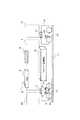
電車や機関車などの鉄道車両の電気車駆動装置では、安全性や迅速な納期が求められる。一般に電気車駆動装置は、主にブレーキ制御装置、主電動機、VVVFインバータから構成される。そして従来は、図5に示す構成であり、車体1内に車内LAN8が設置され、端末装置5と中央処理装置6とがこの車内LAN8にて接続され、また、車体1の屋根上にはパンタグラフ2だけが設置され、電気車駆動装置のうちブレーキ制御装置(図示せず)、LCフィルタ回路3、VVVFインバータ13が車体1の床下に装荷され、台車内には車輪16を駆動するための主電動機14やそれにブレーキ力を作用させるブレーキシュー15などが配置されていた。そのため、台車内の主電動機14から動力線や速度検出器の信号線などが車体1側に渡るなど配線および配管が複雑になっており、車両製作に工数を要する問題点があった。また、上記のように駆動系の機器の設置場所が台車内と車体1側とに分散することで、不具合や故障が生じても、どの装置を交換すべきかが明確でなく、復旧に時間を要する問題点もあった。
本発明は、上記のような従来技術の問題点に鑑みてなされたもので、鉄道車両システムの信頼性を向上させることができる電気車駆動装置を提供することを目的とする。 The present invention has been made in view of the above-described problems of the prior art, and an object thereof is to provide an electric vehicle drive device that can improve the reliability of a railway vehicle system.
本発明は、電気車を駆動する主電動機と前記主電動機を駆動するためのVVVFインバータと車輪のブレーキ力を制御するブレーキ制御装置とを装荷した動力台車を車体の下に備えると共に、少なくとも前記主電動機及びVVVFインバータを装荷しない付随台車を前記車体の下に備え、前記付随台車の取り付け部には、前記動力台車の取り付けを可能にし、前記動力台車、付随台車それぞれと車体との接続部それぞれには、直流電源、アース、ブレーキ用の配管を一体化した共通のコネクタそれぞれを備え、編成としての出力を前記動力台車および付随台車の数で調整可能とした電気車駆動装置を特徴とする。The present inventionRutotomoni comprises a driving truck loaded with a brake control device for controlling the VVVF braking force of the inverter and the wheel for driving a main motor for driving an electric vehicle with the main motorunder the vehiclebody,at least the An accompanying carriage that is not loaded with a main motor and a VVVF inverter is provided below the vehicle body, and the power carriage can be attached to the attachment part of the accompanying carriage, and each of the connecting parts between the power carriage and the associated carriage and the vehicle body is provided. Is characterizedby an electric vehicle driving apparatus thatincludes common connectors each integrating a DC power supply, grounding, and brake piping, and that can adjust the output as a knitting according to the number of the power trolley and the associated trolley .
本発明によれば、電気車を駆動する主電動機と主電動機駆動のためのVVVFインバータとブレーキ制御装置とを動力台車内に備えたことにより、従来のように電気車駆動に関わる機器装置が車体と台車とに分散されることに起因していたぎ装配線の複雑化による車両製造工期の増大や故障復旧時間の増大といった鉄道車両システムの信頼性の劣化を改善することができる。また、車体側では付随台車の取り付け部に動力台車を取り付け可能にし、付随台車であろうと動力台車であろうといずれも接続可能であるように共通のコネクタを備えたことにより、車両の運用状況に応じて、付随台車の取り付け部に動力台車を取り付けることができ、容易にその車両性能を変更することが可能である。According to the present invention, a main motor for driving an electric vehicle, a VVVF inverter for driving the main motor, and a brake control device are provided in the power carriage, so that the device apparatus related to the electric vehicle driving as in the prior art can be It is possible to improve the deterioration of the reliability of the railway vehicle system, such as an increase in the vehicle manufacturing period and an increase in the failure recovery time due to the complicated wiring arrangement caused by being distributed between the vehicle and the carriage.In addition, the vehicle body is equipped with a common connector so that the power truck can be attached to the attachment part of the accompanying truck and can be connected regardless of whether it is an accompanying truck or a power truck. Accordingly, the power carriage can be attached to the attachment portion of the accompanying carriage, and the vehicle performance can be easily changed.
以下、本発明の実施の形態を図に基づいて詳説する。 Hereinafter, embodiments of the present invention will be described in detail with reference to the drawings.
(第1の実施の形態)本発明の第1の実施の形態の電気車駆動装置を、図1を用いて説明する。直流電車の車体1には、動力台車9と付随台車10とが接続されている。車体1の屋根上には、パンタグラフ2、LCフィルタ回路3、そして圧縮空気用のコンプレッサ4が設置されている。また、車体1には、中央処理装置6と無線通信機能を有する指令送信装置7とが設置され、両者間は車内LAN8にて接続されている。 (First Embodiment) An electric vehicle driving apparatus according to a first embodiment of the present invention will be described with reference to FIG. A
動力台車9には、動輪となる車輪16を回転駆動するための主電動機14と、この主電動機14を駆動制御するVVVFインバータ13と、車輪16に対するブレーキシュー15のブレーキ力を制御するブレーキ制御装置12とが備えられている。一方、付随台車10には、ブレーキ制御装置12のみが備えられている。これらの動力台車9内のVVVFインバータ13とブレーキ制御装置12、また付随台車10内のブレーキ制御装置12への制御指令やそれらからの応答の一部は、指令送信装置7によって無線信号にて送受信する。 The
動力台車9と車体1との接続部にはコネクタ11が設けてあり、電源プラス線、アース線、ブレーキ制御用の圧縮空気配管が配置されている。動力台車9とともに、付随台車10側にも同一のコネクタ11が設けてあり、この付随台車10側のコネクタ11にも電源プラス線が配線されている。 A
VVVFインバータ13には、車体1側より直流電源のプラス側が供給される。車輪16、レール17がアース兼マイナス側(−)であるので、動力台車9内にてこのマイナス側(−)と接続している。 The positive side of the DC power source is supplied to the
車体1側の直流電源(+)は、パンタフラフ2を介して受電し、LCフィルタ回路3を経てコネクタ11に配電している。また、コンプレッサ4からのブレーキ用の圧縮空気Airもそれぞれのコネクタ11を介して動力台車9と付随台車11へ供給している。 The DC power source (+) on the vehicle body 1 side receives power via the pantograph 2 and distributes power to the
本実施の形態の電気車駆動装置では、車両の加減速力を生み出し制御する主電動機14、VVVFインバータ13、ブレーキ制御装置12のすべてが動力台車9内に収められている。そのため、故障の際には台車単位ごと交換すれば完全に復旧できる。このため、原因を特定する時間が省き、迅速に復旧できるために鉄道車両システムの信頼性の向上に寄与できる。また、車体1側のぎ装配線が簡略化されるため、予め、台車9,10単位でのぎ装配線を実施しておけば、車両全体を組み合わせてからの作業工数を短縮することができる。また、古くなった車両をリニューアルする際の作業や性能の向上した新たな台車あるいはVVVFインバータといった機器の交換する作業が容易である。 In the electric vehicle drive device of the present embodiment, the
また、本実施の形態によれば、台車9,10と車体1を渡る配線・配管数を低減できるとともに、それらをコネクタ11に集約することで迅速な台車交換が可能となる。この点からも、平均復旧時間(MTTR)を短縮し、鉄道車両システムの信頼性を向上することができる。 In addition, according to the present embodiment, the number of wires and pipes passing between the
また、本実施の形態によれば、VVVFインバータ13の直流マイナス側(−)を台車9,10内のアースへ接続することで不要な配線を減らし、ぎ装配線の容易化、ひいては車体製造工期の短縮化やメンテナンスの簡易化に寄与できる。 Further, according to the present embodiment, by connecting the DC negative side (−) of the VVVF inverter 13 to the ground in the
また、本実施の形態によれば、車体1側では付随台車10であろうと動力台車9であろうといずれも接続可能であるように共通のコネクタ11を備えている。これにより、車両の運用状況に応じて、容易にその車両性能を変更することが可能である。例えば、普通車両は、急行車両に比べて低速で冷却が期待できない上、発熱が大きい加減速を繰り返す。すなわち、急行車両性能と普通車両性能は異なっている。そのため、従来では、いずれか一方の用途用に設計された車両は他方の種別にて用いることができない場合があった。ところが、本実施の形態では、付随台車10に置き換えて動力台車9を車体1に取り付けるだけでこれが実現可能となる。これにより、本実施の形態によれば、鉄道事業者にとって車両の運行管理を容易にし、車両を種別に応じて余分に持つという不要な設備投資を軽減できる効果がある。 Further, according to the present embodiment, the
さらに、本実施の形態によれば、動力台車9には1つの主電動機14とVVVFインバータ13を装荷することで台車内の空間にゆとりが生じさせることができる。現状の鉄道車両は、主電動機を有した車軸とそれを持たない車軸との比が1:1程度あることから、1つの台車(台車には2つの車軸がある)には、1つの主電動機を備える点で妥当である。鉄道事業者にとっては、異なる台車を管理するより、同一の台車を管理する方が安全性、コストの面で利点がある。 Furthermore, according to the present embodiment, a space can be generated in the carriage by loading one
またさらに、本実施の形態によれば、共通機器であるLCフィルタ回路3、コンプレッサ4を車体1の屋根上に配置したことで、車体1の床下スペースを有効に利用することが可能となる。例えば、この床下空間を広く広げることで、2階建て車両の適用が図れる。鉄道事業者にとっては、2階建て車両により、定員の増大による通勤混雑緩和、輸送能力の増大による収益改善などの効果が得られる。 Furthermore, according to the present embodiment, by arranging the
加えて、本実施の形態では、動力台車9、付随台車10への制御指令やそれらからの応答の一部を指令送信装置7によって無線で通信するようにしている。これにより、取り扱いに注意を要し、ぎ装配線にも手間のかかる弱電線を撤廃することが可能であり、ぎ装配線の簡易化、メンテナンスの低減とともに、台車交換を容易にし、MTTRの短縮による信頼性向上、動力台車と付随台車の任意交換の実現などに寄与できる。 In addition, in the present embodiment, control commands to the
(第2の実施の形態)図2を用いて、本発明の第2の実施の形態の電気車駆動装置について説明する。本実施の形態は、図1に示した第1の実施の形態に対して、付随台車10の代わりに動力台車9が備え、車体1に対して2台の動力台車9を備え、また、車体1の屋根上にDC/DCコンバータ18を追加的に備えたことを特徴とする。尚、図2において、図1の第1の実施の形態と共通する要素については共通の符号を付して示してある。 (Second Embodiment) An electric vehicle drive apparatus according to a second embodiment of the present invention will be described with reference to FIG. This embodiment is different from the first embodiment shown in FIG. 1 in that a
2台の動力台車9の電源は共通の回路として与えられ、この共通電源回路は、LCフィルタ回路3とDC/DCコンバータ18にて構成されている。DC/DCコンバータ18はLCフィルタ回路3の直流出力を昇圧ないしは降圧するものである。 The power sources of the two
本実施の形態によれば、複数の動力台車9それぞれの内に装荷されたVVVFインバータ13の直流電源入力回路として各台車毎に機器を持つのではなく、台車間をまたがって共通化して使うことで機器集中化が図れ、これにより、車体1側の機器の小型・軽量化が図れ、それに応じて製造コストも低減できる。 According to this embodiment, the DC power supply input circuit of the
(第3の実施の形態)本発明の第3の実施の形態の電気車駆動装置について、図3を用いて説明する。本実施の形態は、図1に示した第1の実施の形態に対して、車体1の床下にエネルギー蓄積装置19を備えたことを特徴とする。このエネルギー蓄積装置19は、大容量のエネルギーの充電あるいは放電が可能な装置であり、例えば、電気二重層コンデンサ(EDLC)、2次電池、燃料電池あるいはディーゼルエンジンなどである。尚、図3に示す第3の実施の形態におけるその他の要素については、図1に示した第1の実施の形態と共通する。 (Third Embodiment) An electric vehicle driving apparatus according to a third embodiment of the present invention will be described with reference to FIG. This embodiment is characterized in that an
本実施の形態によれば、従来は車体1の床下に配置されていたVVVFインバータ13、ブレーキ制御装置13を主電動機14とともに動力台車9内に備えることで、車体1の床下に大きなスペースが生まれる。エネルギー蓄積装置19の搭載車両は、省エネルギーや車両の自律走行というメリットから様々提案されているが、従来は現実的に搭載できるスペースがなかった。ところが、本実施の形態によれば、開放された床下空間を利用し、大容量なエネルギー蓄積装置19が搭載できるようになり、その結果、第1の実施の形態の効果とともに、省エネルギーや車両の自律走行という効果も奏する。 According to the present embodiment, a large space is created under the floor of the vehicle body 1 by providing the
(第4の実施の形態)図4を用いて、本発明の第4の実施の形態の電気車駆動装置について説明する。本実施の形態は、図3に示した第3の実施の形態に対して車体1と動力台車9との位置関係が異なる。本実施の形態で採用している台車は連接台車といわれるもので、車体1と車体20の中間に動力台車9が配置され、また付随台車10は車体1と車体21の中間に配置されている。尚、電気系統の配線、コンプレッサ4からの圧縮空気Airの配管は第3の実施の形態と同様である。そして、本実施の形態の特徴は、第3の実施の形態と同様に、車体1の床下の空きスペースにエネルギー蓄積装置19を設置したことにある。(Fourth Embodiment) An electric vehicle drive apparatus according to a fourth embodiment of the present invention will be described with reference to FIG. This embodiment differs from the third embodiment shown in FIG. 3 in the positional relationship between the vehicle body 1 and the
本実施の形態のように、元来車体1の床下に備わるVVVFインバータ13やブレーキ制御装置12などを動力台車9内に収めることで車体1の床下の空きスペースを拡大することができる上、さらに連接台車方式を採用することでより車体1の床下に一層広い空きスペースを開放することができる。そこで、この車体1の床下の広い空きスペースを利用してエネルギー蓄積装置19を設置することで、第3の実施の形態のものよりも大容量のものの搭載が可能になる。 As in the present embodiment, the space under the floor of the vehicle body 1 can be expanded by housing the
尚、本実施の形態において、車体1の床下の空きスペースが広くできることから、2階建て電車に仕上げれば定員を広げる効果を享受できる。また、床下空間に新たな装置を積むのではなく、低床にしてバリアフリー化することで、高齢化社会に向けて人に優しい鉄道システムが構築できる。さらに、低床式にして地下鉄に適用すれば車両断面積を低減し、大幅な土木の削減効果が期待できる。 In addition, in this Embodiment, since the empty space under the floor of the vehicle body 1 can be widened, if it finishes on a two-story train, the effect of expanding the capacity can be enjoyed. In addition, by installing a low floor and making it barrier-free rather than installing new equipment in the underfloor space, a railway system that is friendly to people can be built for an aging society. Furthermore, if it is applied to a subway with a low floor type, the vehicle cross-sectional area can be reduced, and a significant civil engineering reduction effect can be expected.
1…車体
2…パンタグラフ
3…フィルタ回路
4…コンプレッサ
6…中央処理装置
7…指令送信装置
8…車内LAN
9…動力台車
10…付随台車
11…コネクタ
12…ブレーキ制御装置
13…VVVFインバータ
14…主電動機
15…ブレーキシュー
16…車輪
17…レール
18…DC/DCコンバータ
19…エネルギー蓄積装置
20,21…車体DESCRIPTION OF SYMBOLS 1 ... Vehicle body 2 ...
DESCRIPTION OF
Claims (11)
Translated fromJapanese前記付随台車の取り付け部には、前記動力台車の取り付けを可能にし、
前記動力台車、付随台車それぞれと車体との接続部それぞれには、直流電源、アース、ブレーキ用の配管を一体化した共通のコネクタそれぞれを備え、
編成としての出力を前記動力台車および付随台車の数で調整可能としたことを特徴とする電気車駆動装置。Rutotomoni comprising a driving truck loaded with a brake control device for controlling the VVVF braking force of the inverter and the wheel for driving the main motor and the main motor for driving an electric vehicleunder the vehiclebody,at least the main electric motor and VVVF An accompanying carriage that does not load an inverter is provided under the vehicle body,
In the attachment part of the accompanying carriage, it is possible to attach the power carriage,
Each of the connecting parts of the power trolley, the associated trolley and the vehicle body is provided with a common connector integrated with a DC power source, a ground, and a brake pipe.
An electric vehicle driving device characterized in that anoutput as a knitting can be adjusted by the number of the power trolley and the accompanying trolley .
Priority Applications (4)
| Application Number | Priority Date | Filing Date | Title |
|---|---|---|---|
| JP2006168853AJP4874718B2 (en) | 2006-06-19 | 2006-06-19 | Electric car drive |
| US11/759,589US20080011185A1 (en) | 2006-06-19 | 2007-06-07 | Electric rolling stock driving apparatus |
| EP07011554AEP1870275A2 (en) | 2006-06-19 | 2007-06-13 | Electric rolling stock driving apparatus |
| CN200710112156.9ACN101092116B (en) | 2006-06-19 | 2007-06-19 | Electric rolling stock drive equipment |
Applications Claiming Priority (1)
| Application Number | Priority Date | Filing Date | Title |
|---|---|---|---|
| JP2006168853AJP4874718B2 (en) | 2006-06-19 | 2006-06-19 | Electric car drive |
Publications (2)
| Publication Number | Publication Date |
|---|---|
| JP2007336779A JP2007336779A (en) | 2007-12-27 |
| JP4874718B2true JP4874718B2 (en) | 2012-02-15 |
Family
ID=38537563
Family Applications (1)
| Application Number | Title | Priority Date | Filing Date |
|---|---|---|---|
| JP2006168853AExpired - Fee RelatedJP4874718B2 (en) | 2006-06-19 | 2006-06-19 | Electric car drive |
Country Status (4)
| Country | Link |
|---|---|
| US (1) | US20080011185A1 (en) |
| EP (1) | EP1870275A2 (en) |
| JP (1) | JP4874718B2 (en) |
| CN (1) | CN101092116B (en) |
Families Citing this family (8)
| Publication number | Priority date | Publication date | Assignee | Title |
|---|---|---|---|---|
| JP5889512B2 (en) | 2008-12-24 | 2016-03-22 | 株式会社東芝 | Vehicle drive device |
| JP2011019326A (en)* | 2009-07-08 | 2011-01-27 | Toshiba Corp | Train control system |
| DE102009042870A1 (en)* | 2009-09-24 | 2011-03-31 | Siemens Aktiengesellschaft | Rail vehicle with single wheel drives |
| DE102010025036A1 (en)* | 2010-06-24 | 2011-12-29 | Siemens Aktiengesellschaft | track vehicle |
| JP5662251B2 (en)* | 2011-06-02 | 2015-01-28 | 鹿島建設株式会社 | Grounding method in tunnel construction |
| US9132843B2 (en)* | 2013-05-28 | 2015-09-15 | Electro-Motive Diesel, Inc. | Communication system for use with train consist |
| JP6666815B2 (en)* | 2016-09-06 | 2020-03-18 | 株式会社日立製作所 | Cooling device, bogie and railcar equipped with cooling device |
| GB2603202B (en)* | 2021-02-02 | 2024-02-28 | The Council Of The City Of Coventry | Bogie for a light rail system |
Family Cites Families (26)
| Publication number | Priority date | Publication date | Assignee | Title |
|---|---|---|---|---|
| DE3130603A1 (en)* | 1981-08-01 | 1983-02-17 | Krauss-Maffei AG, 8000 München | DRIVE BOG FOR A RAIL VEHICLE |
| DE3523570C1 (en)* | 1985-07-02 | 1986-06-26 | Messerschmitt-Bölkow-Blohm GmbH, 8012 Ottobrunn | Process for producing a fibre-composite winding skin |
| JPH03106208A (en)* | 1989-09-20 | 1991-05-02 | Sanyo Electric Co Ltd | Sound field correction device |
| JPH03261307A (en)* | 1990-03-09 | 1991-11-21 | East Japan Railway Co | Control method of inverter for driving electric car and inverter drive electric car system |
| JP2824142B2 (en)* | 1990-09-18 | 1998-11-11 | 川重鉄道車両エンジニアリング株式会社 | Train composition array |
| JPH0515012A (en)* | 1991-06-28 | 1993-01-22 | Toshiba Corp | Controlling method for individual axle of electric motor vehicle |
| JP3209288B2 (en)* | 1992-07-29 | 2001-09-17 | 財団法人鉄道総合技術研究所 | Brake equipment for railway vehicles |
| US5595121A (en)* | 1994-04-15 | 1997-01-21 | The Walt Disney Company | Amusement ride and self-propelled vehicle therefor |
| JPH0833122A (en)* | 1994-07-14 | 1996-02-02 | Fuji Heavy Ind Ltd | Electric dual mode railway vehicle |
| CA2140398A1 (en)* | 1994-11-16 | 1996-05-17 | Gregory S. Balukin | Apparatus to enable controlling a throttle controller from a remote host |
| US6474242B1 (en)* | 1997-11-05 | 2002-11-05 | Michael Baier | Rail vehicle system |
| JP3297371B2 (en)* | 1998-03-12 | 2002-07-02 | 株式会社東芝 | Electric car control device |
| US6123029A (en)* | 1998-04-01 | 2000-09-26 | Mobley; Joseph T. | Intermodal transport system |
| PL348733A1 (en)* | 1998-10-23 | 2002-06-03 | Knorr Bremse Systeme | Brake system for railway vehicles |
| FR2788739B1 (en)* | 1999-01-27 | 2001-03-02 | Alstom | MODULAR RAILWAY AND RAILWAY CONVEYOR FORMED IN SUCH ROWS |
| JP2001136603A (en)* | 1999-11-01 | 2001-05-18 | Central Japan Railway Co | Rolling stock for regenerating and reusing energy |
| JP2001315642A (en)* | 2000-05-01 | 2001-11-13 | Kawasaki Heavy Ind Ltd | Bolt fastening structure for railway vehicles |
| US7430967B2 (en)* | 2001-03-27 | 2008-10-07 | General Electric Company | Multimode hybrid energy railway vehicle system and method |
| FR2826328B1 (en)* | 2001-06-26 | 2003-08-29 | Alstom | MOTOR BOGIE FOR RAILWAY VEHICLE WITH INTEGRAL LOW FLOOR |
| JP3677248B2 (en)* | 2002-03-14 | 2005-07-27 | 近畿車輌株式会社 | Articulated vehicle with low floor |
| JP3881317B2 (en)* | 2003-01-30 | 2007-02-14 | 川崎重工業株式会社 | Battery box for railway vehicles |
| JP2004312953A (en)* | 2003-04-10 | 2004-11-04 | Hitachi Ltd | Hybrid transport vehicle |
| JP4167948B2 (en)* | 2003-08-13 | 2008-10-22 | 財団法人鉄道総合技術研究所 | Railway vehicle |
| JP2005153760A (en)* | 2003-11-27 | 2005-06-16 | Hitachi Ltd | Railway vehicle drive system |
| JP2005218185A (en)* | 2004-01-28 | 2005-08-11 | Hitachi Ltd | Railway vehicle for freight transportation |
| WO2005097573A2 (en)* | 2004-03-30 | 2005-10-20 | Railpower Technologies Corp. | Emission management for a hybrid locomotive |
- 2006
- 2006-06-19JPJP2006168853Apatent/JP4874718B2/ennot_activeExpired - Fee Related
- 2007
- 2007-06-07USUS11/759,589patent/US20080011185A1/ennot_activeAbandoned
- 2007-06-13EPEP07011554Apatent/EP1870275A2/ennot_activeWithdrawn
- 2007-06-19CNCN200710112156.9Apatent/CN101092116B/ennot_activeExpired - Fee Related
Also Published As
| Publication number | Publication date |
|---|---|
| US20080011185A1 (en) | 2008-01-17 |
| JP2007336779A (en) | 2007-12-27 |
| EP1870275A2 (en) | 2007-12-26 |
| CN101092116A (en) | 2007-12-26 |
| CN101092116B (en) | 2010-09-22 |
Similar Documents
| Publication | Publication Date | Title |
|---|---|---|
| JP4874718B2 (en) | Electric car drive | |
| CN103781688B (en) | Rail vehicle system | |
| JP5121191B2 (en) | Low-floor railway vehicles and low-floor trams | |
| CN101837740B (en) | Railway system installing power supply facility on railroads between stations | |
| CN108473114B (en) | Vehicle with braking device | |
| KR101723344B1 (en) | Passenger transport railcar | |
| CN202320277U (en) | Frame control brake system and railway vehicle | |
| JP2008195383A (en) | Railway car for passenger transport | |
| CN104540714A (en) | Train-information management device and device control method | |
| KR101723347B1 (en) | Passenger transport railcar | |
| CN107683228A (en) | Regenerate railway brake system | |
| CN101786468A (en) | Steering device and chassis | |
| CN105235758B (en) | The rubber tire low-floor intelligent track train that a kind of power decentralized type track follows | |
| US10611385B2 (en) | Rail vehicle, method for driving a rail vehicle and method for producing a rail vehicle | |
| JP7190946B2 (en) | Power supply, automatic steering vehicle, and power supply method | |
| RU2007112826A (en) | METHOD FOR FORMING TRAINS FROM SEPARATE CARS | |
| JP4636757B2 (en) | Railway vehicle drive system | |
| JP6629138B2 (en) | Compressed air supply device | |
| CN113997958A (en) | Three-power locomotive group with power battery car and extensible traction topological structure | |
| KR100661733B1 (en) | Salvation operation method using TCMC | |
| CN119731043A (en) | Central electrical device for operating an electrical drive and/or a regenerative axle of a trailer or semitrailer of a commercial vehicle | |
| CN112849162B (en) | Motor train unit train | |
| WO2006103636A2 (en) | Braking system for a railway or tramway vehicle | |
| CN220924281U (en) | Chassis module of extended range electric automobile and extended range electric automobile | |
| JP2011131847A (en) | Hand brake detection system of railroad vehicle |
Legal Events
| Date | Code | Title | Description |
|---|---|---|---|
| A621 | Written request for application examination | Free format text:JAPANESE INTERMEDIATE CODE: A621 Effective date:20090417 | |
| A131 | Notification of reasons for refusal | Free format text:JAPANESE INTERMEDIATE CODE: A131 Effective date:20110215 | |
| A521 | Request for written amendment filed | Free format text:JAPANESE INTERMEDIATE CODE: A523 Effective date:20110415 | |
| TRDD | Decision of grant or rejection written | ||
| A01 | Written decision to grant a patent or to grant a registration (utility model) | Free format text:JAPANESE INTERMEDIATE CODE: A01 Effective date:20111101 | |
| A01 | Written decision to grant a patent or to grant a registration (utility model) | Free format text:JAPANESE INTERMEDIATE CODE: A01 | |
| A61 | First payment of annual fees (during grant procedure) | Free format text:JAPANESE INTERMEDIATE CODE: A61 Effective date:20111124 | |
| FPAY | Renewal fee payment (event date is renewal date of database) | Free format text:PAYMENT UNTIL: 20141202 Year of fee payment:3 | |
| FPAY | Renewal fee payment (event date is renewal date of database) | Free format text:PAYMENT UNTIL: 20141202 Year of fee payment:3 | |
| LAPS | Cancellation because of no payment of annual fees |