JP4874459B2 - Threaded union - Google Patents
Threaded unionDownload PDFInfo
- Publication number
- JP4874459B2 JP4874459B2JP2000285466AJP2000285466AJP4874459B2JP 4874459 B2JP4874459 B2JP 4874459B2JP 2000285466 AJP2000285466 AJP 2000285466AJP 2000285466 AJP2000285466 AJP 2000285466AJP 4874459 B2JP4874459 B2JP 4874459B2
- Authority
- JP
- Japan
- Prior art keywords
- screw member
- annular
- female screw
- male screw
- peripheral surface
- Prior art date
- Legal status (The legal status is an assumption and is not a legal conclusion. Google has not performed a legal analysis and makes no representation as to the accuracy of the status listed.)
- Expired - Lifetime
Links
- 230000002093peripheral effectEffects0.000claimsdescription22
- 230000008878couplingEffects0.000claimsdescription9
- 238000010168coupling processMethods0.000claimsdescription9
- 238000005859coupling reactionMethods0.000claimsdescription9
- 238000003780insertionMethods0.000claimsdescription4
- 230000037431insertionEffects0.000claimsdescription4
- 239000007789gasSubstances0.000description4
- 239000007788liquidSubstances0.000description3
- 239000002184metalSubstances0.000description3
- 230000009471actionEffects0.000description2
- 230000006835compressionEffects0.000description2
- 238000007906compressionMethods0.000description2
- 239000000463materialSubstances0.000description2
- 239000003208petroleumSubstances0.000description2
- 230000008719thickeningEffects0.000description2
- 230000008859changeEffects0.000description1
- 238000010586diagramMethods0.000description1
- 239000012530fluidSubstances0.000description1
- 230000006872improvementEffects0.000description1
- 230000007257malfunctionEffects0.000description1
- 238000004519manufacturing processMethods0.000description1
- 238000000034methodMethods0.000description1
- 230000002028prematureEffects0.000description1
- 239000000565sealantSubstances0.000description1
- 238000007789sealingMethods0.000description1
- 230000035945sensitivityEffects0.000description1
- 230000007704transitionEffects0.000description1
- 238000003466weldingMethods0.000description1
Images


Classifications
- F—MECHANICAL ENGINEERING; LIGHTING; HEATING; WEAPONS; BLASTING
- F16—ENGINEERING ELEMENTS AND UNITS; GENERAL MEASURES FOR PRODUCING AND MAINTAINING EFFECTIVE FUNCTIONING OF MACHINES OR INSTALLATIONS; THERMAL INSULATION IN GENERAL
- F16L—PIPES; JOINTS OR FITTINGS FOR PIPES; SUPPORTS FOR PIPES, CABLES OR PROTECTIVE TUBING; MEANS FOR THERMAL INSULATION IN GENERAL
- F16L15/00—Screw-threaded joints; Forms of screw-threads for such joints
- F16L15/001—Screw-threaded joints; Forms of screw-threads for such joints with conical threads
- F16L15/004—Screw-threaded joints; Forms of screw-threads for such joints with conical threads with axial sealings having at least one plastically deformable sealing surface
- E—FIXED CONSTRUCTIONS
- E21—EARTH OR ROCK DRILLING; MINING
- E21B—EARTH OR ROCK DRILLING; OBTAINING OIL, GAS, WATER, SOLUBLE OR MELTABLE MATERIALS OR A SLURRY OF MINERALS FROM WELLS
- E21B17/00—Drilling rods or pipes; Flexible drill strings; Kellies; Drill collars; Sucker rods; Cables; Casings; Tubings
- E21B17/02—Couplings; joints
- E21B17/04—Couplings; joints between rod or the like and bit or between rod and rod or the like
- E21B17/042—Threaded
Landscapes
- Engineering & Computer Science (AREA)
- Geology (AREA)
- Life Sciences & Earth Sciences (AREA)
- Mechanical Engineering (AREA)
- Mining & Mineral Resources (AREA)
- General Engineering & Computer Science (AREA)
- Physics & Mathematics (AREA)
- Environmental & Geological Engineering (AREA)
- Fluid Mechanics (AREA)
- General Life Sciences & Earth Sciences (AREA)
- Geochemistry & Mineralogy (AREA)
- Non-Disconnectible Joints And Screw-Threaded Joints (AREA)
- Joints With Pressure Members (AREA)
- Earth Drilling (AREA)
Description
Translated fromJapanese【0001】
【発明の属する技術分野】
本発明は、オーバトルク並びに圧縮に対する耐性が高く、チューブ状部材相互を接続するためのユニオン(結合管)に使用されるねじ付きユニオンに関し、特に、これに限定されるものではないが、蒸気、ガス、石油のような液体もしくは圧縮気体を搬送するパイプに使用され、また、探査コラムもしくはガスまたは石油生成で使用されるか、液体もしくは気体を送るパイプラインで使用されるユニオンに関する。
【0002】
【従来技術】
上述した目的のために、今日使用されている主な形式の接続体は、ねじが形成された内周面を有する雄ねじ部材と、この雌ねじに対応するねじが形成された外周面を有する雄ねじ部材とにより構成され、雄ねじ部材が雌ねじ部材の中にねじ結合により受け入れられるようになっている。そして、ノーズと呼ばれている、一方の部材(通常は雄ねじ部材)の自由端部は、軸方向に向いた環状面を有する。この環状面は、他方の部材の対応する面(トルクのショルダー)に押圧(プレス)される。このような形式の接続体において、一方の部材の自由端部に径方向に向いた他の面が形成されている場合と無い場合とがある。この面は、他方の部材に対して径方向に向いた対応する面にプレスされたときに、シールするように機能する。このような接続がなされると、軸方向に向いた環状面は、圧縮されている。このような接続体が吸収可能な最大トルクは、一方の部材の自由端部と、トルク領域のショルダーとのディメンションとデザインとにより制限を受ける。現在の接続体は、雄ねじ部材の自由端部の軸方向に向いた面と、雌ねじ部材の対応する面とのディメンション間で類似性、並びに前記ノーズの抵抗領域とショルダーの抵抗領域との間で類似性を持っている。しかし、組み立ての間、もしくはこれに続く、組み立てられたコラムでの動作の間に、接続体に加わるトルクが高くなったときに、トルクのショルダーに発生されるテンションの組合わせは、材料を剪断するストレスを生じさせて、ショルダーの破断を誘起し、ねじりストレスにより接続体に弱い点もしくは限界領域を生じさせる。のような種類のストレスに対して接続体の仕様を改良するためには、ノーズの厚さと、トルクのショルダーの厚さとを同じようにして厚くして、オーバトルク支持力を高めることが一般的である。
【0003】
【発明が解決しようとする課題】
しかし、このことは、ノーズの剛性が大きくなって接触圧力が高くなるので、シールの感受性が高くなって動作不良となる。さらに、ノーズを厚くすると、ねじ込む前に、パイプの自由端部を調節しなければならなくなる。これは、材料の性質に影響し、また、製造プロセスが複雑になる。
【0004】
本発明の主目的は、ねじりストレスに対する接続能力を高めながら、トルクのショルダーの早期故障のような上記分野での現状の問題点を解決もしくは減じることの可能な、改良されたパイプ接続体(ねじ付きユニオン)を提供することである。
また、本発明の目的は、シール面での接触圧力が制限されて維持され、かくして故障の発生するリスクを減じることが可能なパイプ接続体を提供することである。
本発明の他の目的は、実質的な変化が生じないで内部で循環する流体の流れラインの形状を安定に維持することの可能なユニオンを提供することである。
【0005】
【課題を解決するための手段】
上記目的を達成するために、本発明のパイプ接続体は、ねじが形成された第1の内周面を有する雌ねじ部材と、この雌ねじ部材の内周面に対応したねじが形成された外周面を有する雄ねじ部材とを具備する。この雄ねじ部材は、雌ねじ部材の中に、ねじ込まれて、これら部材は結合される。ノーズと呼ばれる、一方の部材の自由端部に位置し、ほぼ軸方向に向けられた環状面は、トルクのショルダーと命名された、他方の部材に向かってほぼ軸方向に向けられた対向環状面としっかりと接触する。前記一方の部材の軸方向に向けられた環状面は、小径の所で、パイプの内面と交差している。代わって、これは、パイプの軸に平行な内円周面と交差している。かわって、これは、パイプの内面と交差している切頭円錐形状の面と交差している。一方、他方の部材の軸方向に向けられた環状面は、小径の所で、パイプの軸に対して5°ないし25°の角度Bをなす径方向に向けられた切頭円錐形状の面と交差している。また、この面は、パイプの軸に平行な内円周面と交差している。代わって、この面は、パイプの軸に対して5°未満の角度をなし得る。
【0006】
本発明に係わる、トルクのショルダーの形態は、従来のユニオンではマシーンの損傷の可能性がある主剪断ストレスが発生される、面内のショルダートルクに対する耐性が高くなることにより、ユニオンのオーバトルク能力を高めることができる。かくして、一般に使用されてるジョイントの弱い領域の耐性を実質的に改良することができる。耐性におけるこの改良は、ノーズを厚くすることがなく、また、ノーズが金属対金属接触のシーラント面を有している場合には故障の可能性を高めることがなく、得られる。
【0007】
ある形態に係われば、第1の部材は雄ねじ部材に対応し、これは、雄ねじ部材のパイプの軸に垂直な面に対して角度Aをなすように軸方向に向けられた面を有する。この面は、圧力のもとで、雌ねじ部材のパイプの軸に垂直な面に対して角度Aををなし、ほぼ軸方向に向けられた対応する面と接触する。
【0008】
【発明の実施の形態】
図1は、雄ねじ部材1と雌ねじ部材2とを有する接続体(ユニオン)を示す。この図にて、前記雌ねじ部材は、カップリング3の一端部に形成されている。このカップリングの他端部には、第2の雄ねじ部材1aと接続するための第2の雌ねじ部材2aが設けられている。また、各雄ねじ部材1,1aは、パイプ部分4,4aの一端部に、図示するように、パイプ部分と一体的に形成されるか、別々に形成されて溶接もしくは他の方法で固定され得るようにして、設けられている。
【0009】
図示するように、各雄ねじ部材1,1aは、ねじが形成された、切頭円錐形状の外周面5,5aを有する。また、各雌ねじ部材2,2aは、対応する雄ねじ部材を受けて結合するように、ねじが形成された切頭円錐形状の内周面6,6aを有する。これら部材は、一般的な方法でねじ込まれ得る。両方の周面に形成されたねじは、雄ねじ部材の自由端部7,7aと、雌ねじ部材の対応する内端面との近くで、夫々終わっている。これら部材が充分に結合されたときに、各雄ねじ部材の自由端部7,7aにほぼ軸方向に向いた面(ノーズ)は、図2並びに3に詳細に示されるように、雌ねじ部材のショルダー(トルクのショルダー)8のほぼ軸方向に向けられ、前記面と対向する面と、シールするように当接されている。これら図は、雄ねじ部材1の自由端部7と、ショルダー8の対応する部分と、雌ねじ部材2の当接内面とのみを示している。
【0010】
図2に示されるように、前記雄ねじ部材1の自由端部7(ノーズと呼ばれている)には、径方向に向いた外環状面(第1の面)9と、パイプの軸に垂直な面に対して角度Aを形成するように軸方向に向けられた環状面(第2の面)10とが形成されている。前記外環状面9は、これが、雌ねじ部材の対応する面と接触しているときに、接続体のシールを果たすように設定されている面もしくは環状領域を持っていてもいなくても良い。前記環状面10は、角部(交線)11で終端されている。この角部は、雄ねじ部材の内面での所定の内径を有している。環状面10の角部と接続している雄ねじ部材の内周面には、中心軸に平行な実線で示す面12は形成されておらず、破線で示された切頭円錐形状の面13が形成されている。この面13は、雄ねじ部材の内周面の所で終端している。前記第1並びに第2の面9,10は、曲率半径がR1の環状面14により接続されている。この雄ねじ部材の特徴として、このノーズと呼ばれている部分は、パイプの軸に垂直な面で見た場合の、前記第1並びに第2の面9,10の仮想交線と、第2の面10の終端の角部(交線)11との間の距離であるノーズの厚さTnで規定されている。
【0011】
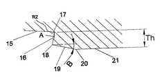
図3に示されているように、前記雌ねじ部材2には、雄ねじ部材の前記面9,10に対応する面15,16が形成されている。これら面15,16は、曲率半径がR2の環状面17によって互いに接続されている。この曲率半径R2は、組み立ての理由により、前記曲率半径R1よりも大きくなければならない。前記面16は、角部(交線)18の所で、切頭円錐形の面19と接続されており、この面19は、パイプの軸に対して5°ないし25°の角度Bをなしている。同時に、この面19角部20の所で、内周面21に接続されている。代わって、この面21は、パイプの軸に対して5°未満の角度をなし得る。これら面16,19,21により構成された雌ねじ部材の部分は、組み立てもしくは動作の間のトルク作用による圧縮負荷を支持しなければならない“トルクのショルダー”を構成している。このショルダー厚さThは、面15,16の仮想交線と、面19,21が互いに交わる角部20との間の距離として規定されている。面16,19が角18で互いに交わると、一致した所の径もしくは傾斜端が、代わって含まれ得る。
【0012】
本発明の状態として、以下の関係がノーズの厚さTnとショルダーThの厚さとの間で確立され得る。
【0013】
1.1≦Th/Tn≦1.4
また、本発明で確立された面19の角度は、以下の通りである。
【0014】
5°≦B≦25°
図4は、図2に示された雄ねじ部材の自由端部を、これが図3に示される雌ねじ部材と組合わされた最終位置にあるところを、詳細に示す。前記対応する面10,16は、圧縮負荷のもとで、互いにしっかりと接触している。また、前記面9,15は、接続体がいかなる金属相互のシールによるかによって、接触している場合も、接触していない場合もあり得る。トルク作用が増すことによるストレスの増大がユニオン内の圧縮負荷により両面10,16間の圧力が大きくなった場合には、トルクのショルダーと呼ばれている面16,19,21により規定された領域は、従来のユニオンにより吸収されたテンションよりも高い能力で発生したテンションを吸収するであろう。
さらに、前記面12,19,21は、パイプ内での液体もしくは気体に対して緩やかな遷移を果たしている。
【0015】
本発明は、雌ねじ部材がカップリングに形成されている、接続体の内容について説明されたが、図5に示すような差込み継手にも同様に適用可能である。ここでは、雄ねじ部材22と雌ねじ部材23とは、面が、雄ねじ部材の自由境界部24で図2に示されているのと同様にほぼ軸方向に向けられて、雌ねじ部材23にトルクのショルダー25が設けられ、図3に示されているとの同様に前者に対応市、ほぼ軸方向に向けられた面と接触した状態で、パイプ部分4,4aの端部で一体的に一致されている。
【図面の簡単な説明】
【図1】図1は、本発明の一実施の形態に係わるユニオン(接続体)の縦断面図である。
【図2】図2は、図1に示す接続体の一部を拡大して示す縦断面図である。
【図3】図3は、図1に示す接続体の一部を拡大して示す縦断面図である。
【図4】図4は、接続体が組み立てられたときの、図2並びに3に示す部分を示す図である。
【図5】図5は、本発明の他の実施の形態に係わる接続体の縦断面図である。
【符号の説明】
1,1a…雄ねじ部材、2,2a…雌ねじ部材、4,4a…パイプ部分、5,5a…切頭円錐形状の外周面、6,6a…切頭円錐形状の内周面、7,7a…自由端部(ノーズ)、8…トルクのショルダー、9…外環状面(第1の面)、10…環状面(第2の面)、11…角部(交線)、12…内周面(第3の面)、15,16…面、17…環状面。[0001]
BACKGROUND OF THE INVENTION
The present invention relates to a threaded union that is highly resistant to over-torque and compression and is used in a union (coupling pipe) for connecting tubular members to each other. It relates to unions used in pipes carrying liquids or compressed gases, such as petroleum, and also used in exploration columns or pipelines for sending gas or petroleum or for sending liquids or gases.
[0002]
[Prior art]
For the above-mentioned purpose, the main type of connection body used today is a male screw member having an inner peripheral surface on which a screw is formed and an outer screw member having an outer peripheral surface on which a screw corresponding to the female screw is formed. The male screw member is received in the female screw member by screw connection. And the free end of one member (usually a male screw member) called a nose has an annular surface facing in the axial direction. This annular surface is pressed (pressed) on the corresponding surface (torque shoulder) of the other member. In such a type of connection body, there may be a case where another surface facing in the radial direction is formed on the free end of one member and a case where there is no other surface. This surface functions to seal when pressed to a corresponding surface that is radially oriented with respect to the other member. When such a connection is made, the axially oriented annular surface is compressed. The maximum torque that can be absorbed by such a connection body is limited by the dimensions and design of the free end of one member and the shoulder of the torque region. The current connection is similar between the dimension of the axially facing surface of the free end of the male screw member and the corresponding surface of the female screw member, and between the resistance region of the nose and the resistance region of the shoulder. Have similarity. However, when the torque applied to the connection is increased during assembly or subsequent operation on the assembled column, the combination of tensions generated in the torque shoulder will shear the material. Stress is induced to induce shoulder breakage, and torsional stress causes weak points or limit areas in the connection body. In order to improve the specifications of the connection body against such types of stress, it is common to increase the overtorque support by increasing the thickness of the nose and the shoulder of the torque in the same way. is there.
[0003]
[Problems to be solved by the invention]
However, this increases the rigidity of the nose and increases the contact pressure, which increases the sensitivity of the seal and causes malfunction. In addition, thickening the nose requires adjustment of the free end of the pipe before screwing. This affects the properties of the material and complicates the manufacturing process.
[0004]
The main object of the present invention is to provide an improved pipe connection (screw) capable of solving or reducing current problems in the above fields such as premature failure of the torque shoulder while increasing the connection capacity against torsional stress. Union).
It is another object of the present invention to provide a pipe connection body that can maintain the contact pressure at the sealing surface in a limited manner, and thus reduce the risk of failure.
Another object of the present invention is to provide a union capable of stably maintaining the shape of a fluid flow line circulating therein without substantial change.
[0005]
[Means for Solving the Problems]
In order to achieve the above object, a pipe connector of the present invention includes a female screw member having a first inner peripheral surface on which a screw is formed, and an outer peripheral surface on which a screw corresponding to the inner peripheral surface of the female screw member is formed. And a male screw member. The male screw member is screwed into the female screw member, and these members are coupled. An annular surface, located at the free end of one member, called the nose and oriented generally axially, is the opposite annular surface, generally axially directed towards the other member, named the torque shoulder Contact firmly with. The annular surface directed in the axial direction of the one member intersects the inner surface of the pipe at a small diameter. Instead, it intersects the inner circumference parallel to the axis of the pipe. Instead, it intersects a frustoconical surface that intersects the inner surface of the pipe. On the other hand, the annular surface oriented in the axial direction of the other member has a frustoconical surface oriented in the radial direction at an angle B of 5 ° to 25 ° with respect to the axis of the pipe at a small diameter. Crossed. Further, this surface intersects with an inner circumferential surface parallel to the axis of the pipe. Alternatively, this plane may make an angle of less than 5 ° with respect to the axis of the pipe.
[0006]
The torque shoulder configuration according to the present invention increases the resistance of the union to over-torque by increasing the resistance to in-plane shoulder torque, which is the main shear stress that can cause machine damage in conventional unions. Can be increased. Thus, the resistance of commonly used joint weak areas can be substantially improved. This improvement in resistance is obtained without thickening the nose and without increasing the likelihood of failure if the nose has a metal to metal contact sealant surface.
[0007]
According to one form, the first member corresponds to a male thread member, which has an axially oriented surface that makes an angle A with a plane perpendicular to the axis of the pipe of the male thread member. This surface, under pressure, makes an angle A with the surface perpendicular to the axis of the pipe of the female thread member, and makes contact with a corresponding surface oriented substantially in the axial direction.
[0008]
DETAILED DESCRIPTION OF THE INVENTION
FIG. 1 shows a connection body (union) having a male screw member 1 and a female screw member 2. In this figure, the female screw member isformed at one end of the coupling 3 . A second
[0009]
As shown,each of the
[0010]
As shown in FIG. 2, a free end portion 7 (referred to as a nose) of the male screw member 1 has a radially outer ring surface (first surface) 9 and a pipe perpendicular to the axis of the pipe. An annular surface (second surface) 10 oriented in the axial direction so as to form an angle A with respect to the smooth surface is formed. The outer
[0011]
As shown in FIG. 3, the female screw member 2, the
[0012]
As a state of the present invention, the following relationship can be established between the thickness Tn of the nose and the thickness of the shoulder Th.
[0013]
1.1 ≦ Th / Tn ≦ 1.4
The angles of the
[0014]
5 ° ≦ B ≦ 25 °
FIG. 4 shows in detail the free end of the male threaded member shown in FIG. 2 where it is in the final position combined with the female threaded member shown in FIG. The corresponding surfaces 10, 16 are in firm contact with each other under a compressive load. The
Further, the
[0015]
Although the present inventionhas been described with respect to the contents of the connection bodyin which the female screw member isformed in the coupling, the present invention can be similarly applied to an insertion joint as shown in FIG. Here, the
[Brief description of the drawings]
FIG. 1 is a longitudinal sectional view of a union (connector) according to an embodiment of the present invention.
FIG. 2 is an enlarged longitudinal sectional view showing a part of the connection body shown in FIG. 1;
FIG. 3 is an enlarged longitudinal sectional view showing a part of the connection body shown in FIG. 1;
FIG. 4 is a diagram showing the part shown in FIGS. 2 and 3 when the connecting body is assembled.
FIG. 5 is a longitudinal sectional view of a connection body according to another embodiment of the present invention.
[Explanation of symbols]
DESCRIPTION OF
Claims (4)
Translated fromJapaneseこの雌ねじ部材の中に挿入可能であり、前記雌ねじ部材の雌ねじと係合可能な雄ねじが形成され、雌ねじ部材の内周面に対応した外周面を有し、パイプの一端部に形成された環状の雄ねじ部材とを具備し、
これら雌ねじ部材と雄ねじ部材とは、夫々径方向に延びた環状の端面を有し、これら環状の端面は、夫々が互いに同じ長さの外径並びに内径を有し、最終の組み立て位置で、雌ねじ部材と雄ねじ部材との接続部に与えられる圧縮力とトルクの力とを伝達するように、当接し、
前記雌ねじ部材の環状の端面は、前記内径を有する内端の所で、雌ねじ部材の前記内周面に形成され前記環状の端面に向かって大径となるように傾斜した切頭円錐形の面の大径の一端と交わり、この切頭円錐形の面は、前記環状のカップリングもしくは差込み継手の中心軸と所定角度Bをなし、
前記切頭円錐形の面の小径の他端は、雌ねじ部材に形成され、環状のカップリングもしくは差込み継手の中心軸を中心として、この中心軸に平行に延びた環状の内周面部の一端と交わり、
前記雄ねじ部材は、前記内周面の一端と前記環状の端面の内径の内端とを接続するように、内周面と環状の端面との間に形成された切頭円錐形状の面を有し、
前記雌ねじ部材の環状の端面と、切頭円錐形の面と、内周面部とは、トルクのショルダーの一部をなし、以下に規定された傾斜角とディメンションとの組合わせを有することを特徴とするねじ付きユニオン。
1.1≦Th/Tn≦1.4
5°≦B≦25°
ここで、Thは、前記中心軸に平行で、雌ねじ部材の前記環状の端面の内端を通る線と、内周面との間の距離であり、この線は、前記切頭円錐形の面と所定角度Bをなし、前記ショルダーの厚さに対応し、また、Tnは、雄ねじ部材の前記環状の端面の外端と、この環状の端面の内端を通って中心軸に平行に延びた線との間の距離であるノーズの厚さに対応する、ねじ付きユニオン。An annular female screw member having an inner peripheral surface on which an internal thread is formed, and formed on at least one end of an annular coupling or an insertion joint;
A male screw that can be inserted into the female screw member, engageable with the female screw of the female screw member, has an outer peripheral surface corresponding to the inner peripheral surface of the female screw member, and is formed on one end of the pipe. A male screw member,
Each of the female screw member and the male screw member has an annular end face extending in the radial direction, and each of the annular end faces has an outer diameter and an inner diameter of the same length, and the female screw member is in the final assembly position. Abutting so as to transmit the compressive force and torque force applied to the connecting portion between the member and the male screw member;
The end face of the annular said internally threaded member, at the inner end with the inner diameter surface of the frusto-conical is formed in the inner peripheral surface is inclined such that thelarger diameter toward the end face of said annular female screw member one end and intersectionlarge diameter of the surface of the frusto-conical, without a central axis and a predetermined angle B of the annular coupling or bayonet joint,
The other end of thesmall diameter side of the frustoconical is formed in the female screw member, about the central axis of the annular coupling or bayonet joint, one end of the inner surface of the annular extending parallel to the central axis With
The male screw member has a frustoconical surface formed between the inner peripheral surface and the annular end surface so as to connect one end of the inner peripheral surface and the inner end of the inner diameter of the annular end surface. And
The annular end face of the female screw member, the frustoconical surface, and the inner peripheral surface portion form a part of a torque shoulder, and have a combination of an inclination angle and a dimension defined below. Threaded union.
1.1 ≦ Th / Tn ≦ 1.4
5 ° ≦ B ≦ 25 °
Here, Th is a distance between a lineparallel to the central axisand passing through the inner end of the annular end surfaceofthe female screw member, andthe inner peripheral surface , and this line is the frustoconical surface. And Tn extends parallel to the central axis through the outer end of the annular end surface of the male screw member and the inner end of the annular end surface. A threaded union that corresponds to the thickness of the nose, which is the distance between the wires.
Applications Claiming Priority (3)
| Application Number | Priority Date | Filing Date | Title |
|---|---|---|---|
| AR990104738 | 1999-09-21 | ||
| ARP990104738 | 1999-09-21 | ||
| ARP990104738AAR020495A1 (en) | 1999-09-21 | 1999-09-21 | UNION THREADED HIGH RESISTANCE AND COMPRESSION UNION |
Publications (2)
| Publication Number | Publication Date |
|---|---|
| JP2001124252A JP2001124252A (en) | 2001-05-11 |
| JP4874459B2true JP4874459B2 (en) | 2012-02-15 |
Family
ID=3461191
Family Applications (1)
| Application Number | Title | Priority Date | Filing Date |
|---|---|---|---|
| JP2000285466AExpired - LifetimeJP4874459B2 (en) | 1999-09-21 | 2000-09-20 | Threaded union |
Country Status (12)
| Country | Link |
|---|---|
| US (1) | US6557906B1 (en) |
| JP (1) | JP4874459B2 (en) |
| CN (1) | CN1123718C (en) |
| AR (1) | AR020495A1 (en) |
| CA (1) | CA2316142C (en) |
| DE (1) | DE10042209A1 (en) |
| FR (1) | FR2798716B1 (en) |
| GB (1) | GB2356230B (en) |
| ID (1) | ID27266A (en) |
| IT (1) | IT1318738B1 (en) |
| MY (1) | MY125236A (en) |
| PE (1) | PE20010463A1 (en) |
Families Citing this family (79)
| Publication number | Priority date | Publication date | Assignee | Title |
|---|---|---|---|---|
| US7357188B1 (en) | 1998-12-07 | 2008-04-15 | Shell Oil Company | Mono-diameter wellbore casing |
| US7603758B2 (en)* | 1998-12-07 | 2009-10-20 | Shell Oil Company | Method of coupling a tubular member |
| AU2001269810B2 (en) | 1998-11-16 | 2005-04-07 | Shell Oil Company | Radial expansion of tubular members |
| US7185710B2 (en) | 1998-12-07 | 2007-03-06 | Enventure Global Technology | Mono-diameter wellbore casing |
| US6758278B2 (en) | 1998-12-07 | 2004-07-06 | Shell Oil Company | Forming a wellbore casing while simultaneously drilling a wellbore |
| US7363984B2 (en) | 1998-12-07 | 2008-04-29 | Enventure Global Technology, Llc | System for radially expanding a tubular member |
| GB2344606B (en) | 1998-12-07 | 2003-08-13 | Shell Int Research | Forming a wellbore casing by expansion of a tubular member |
| AU770359B2 (en) | 1999-02-26 | 2004-02-19 | Shell Internationale Research Maatschappij B.V. | Liner hanger |
| US7350563B2 (en) | 1999-07-09 | 2008-04-01 | Enventure Global Technology, L.L.C. | System for lining a wellbore casing |
| WO2001098620A1 (en) | 2000-06-20 | 2001-12-27 | Vallourec Mannesmann Oil & Gas France | Tubular threaded joint with reinforced stop |
| US7100685B2 (en)* | 2000-10-02 | 2006-09-05 | Enventure Global Technology | Mono-diameter wellbore casing |
| US6755447B2 (en)* | 2001-08-24 | 2004-06-29 | The Technologies Alliance, Inc. | Production riser connector |
| US7513313B2 (en) | 2002-09-20 | 2009-04-07 | Enventure Global Technology, Llc | Bottom plug for forming a mono diameter wellbore casing |
| AU2002343651A1 (en) | 2001-11-12 | 2003-05-26 | Enventure Global Technology | Collapsible expansion cone |
| WO2003086675A2 (en) | 2002-04-12 | 2003-10-23 | Enventure Global Technology | Protective sleeve for threaded connections for expandable liner hanger |
| WO2003089161A2 (en) | 2002-04-15 | 2003-10-30 | Enventure Global Technlogy | Protective sleeve for threaded connections for expandable liner hanger |
| WO2004018823A2 (en) | 2002-08-23 | 2004-03-04 | Enventure Global Technology | Interposed joint sealing layer method of forming a wellbore casing |
| WO2004018824A2 (en) | 2002-08-23 | 2004-03-04 | Enventure Global Technology | Magnetic impulse applied sleeve method of forming a wellbore casing |
| MXPA04007922A (en) | 2002-02-15 | 2005-05-17 | Enventure Global Technology | Mono-diameter wellbore casing. |
| ITRM20020234A1 (en)* | 2002-04-30 | 2003-10-30 | Tenaris Connections Bv | THREADED JOINT FOR PIPES. |
| ITRM20020274A1 (en) | 2002-05-16 | 2003-11-17 | Tenaris Connections Bv | THREADED JOINT FOR PIPES. |
| US7360591B2 (en) | 2002-05-29 | 2008-04-22 | Enventure Global Technology, Llc | System for radially expanding a tubular member |
| GB2418943B (en) | 2002-06-10 | 2006-09-06 | Enventure Global Technology | Mono Diameter Wellbore Casing |
| AU2003249371A1 (en)* | 2002-07-19 | 2004-02-09 | Enventure Global Technology | Protective sleeve for threaded connections for expandable liner hanger |
| US20060118192A1 (en)* | 2002-08-30 | 2006-06-08 | Cook Robert L | Method of manufacturing an insulated pipeline |
| ITRM20020445A1 (en)* | 2002-09-06 | 2004-03-07 | Tenaris Connections Bv | THREADED JOINT FOR PIPES. |
| AU2003265452A1 (en) | 2002-09-20 | 2004-04-08 | Enventure Global Technology | Pipe formability evaluation for expandable tubulars |
| GB2410280B (en) | 2002-09-20 | 2007-04-04 | Enventure Global Technology | Self-lubricating expansion mandrel for expandable tubular |
| US7886831B2 (en) | 2003-01-22 | 2011-02-15 | Enventure Global Technology, L.L.C. | Apparatus for radially expanding and plastically deforming a tubular member |
| WO2004067961A2 (en) | 2003-01-27 | 2004-08-12 | Enventure Global Technology | Lubrication system for radially expanding tubular members |
| GB2429996B (en) | 2003-02-26 | 2007-08-29 | Enventure Global Technology | Apparatus for radially expanding and plastically deforming a tubular member |
| US20070228729A1 (en)* | 2003-03-06 | 2007-10-04 | Grimmett Harold M | Tubular goods with threaded integral joint connections |
| US20040174017A1 (en)* | 2003-03-06 | 2004-09-09 | Lone Star Steel Company | Tubular goods with expandable threaded connections |
| US20060006648A1 (en)* | 2003-03-06 | 2006-01-12 | Grimmett Harold M | Tubular goods with threaded integral joint connections |
| US7169239B2 (en) | 2003-05-16 | 2007-01-30 | Lone Star Steel Company, L.P. | Solid expandable tubular members formed from very low carbon steel and method |
| UA82694C2 (en)* | 2003-06-06 | 2008-05-12 | Sumitomo Metal Ind | Threaded joint for steel pipes |
| US20050166387A1 (en)* | 2003-06-13 | 2005-08-04 | Cook Robert L. | Method and apparatus for forming a mono-diameter wellbore casing |
| US7712522B2 (en) | 2003-09-05 | 2010-05-11 | Enventure Global Technology, Llc | Expansion cone and system |
| US20050093250A1 (en)* | 2003-11-05 | 2005-05-05 | Santi Nestor J. | High-strength sealed connection for expandable tubulars |
| GB2432866A (en) | 2004-08-13 | 2007-06-06 | Enventure Global Technology | Expandable tubular |
| RU2297512C2 (en)* | 2005-04-01 | 2007-04-20 | ОАО "Таганрогский металлургический завод" | Air-tight threaded oil-field pipe connection |
| FR2890740B1 (en)* | 2005-09-12 | 2007-12-07 | Vallourec Mannesmann Oil Gas F | METHOD FOR PRESSING A THREADED COMPONENT |
| RU2310058C2 (en)* | 2005-09-15 | 2007-11-10 | ОАО "Таганрогский металлургический завод" | Air-tight threaded oilfield pipe connection |
| RU2338866C1 (en) | 2007-02-15 | 2008-11-20 | Общество С Ограниченной Ответственностью "Тмк-Премиум Сервис" | Leakproof screwed connection of oil-field pipes |
| EP2006589B1 (en)* | 2007-06-22 | 2011-08-31 | Tenaris Connections Aktiengesellschaft | Threaded joint with energizable seal |
| DE602007011046D1 (en)* | 2007-06-27 | 2011-01-20 | Tenaris Connections Ag | Threaded connection with pressurizable seal |
| EP2017507B1 (en)* | 2007-07-16 | 2016-06-01 | Tenaris Connections Limited | Threaded joint with resilient seal ring |
| EP2028403B1 (en)* | 2007-08-24 | 2011-04-13 | Tenaris Connections Aktiengesellschaft | Threaded joint with high radial loads and differentially treated surfaces |
| EP2028402B1 (en)* | 2007-08-24 | 2010-09-01 | Tenaris Connections Aktiengesellschaft | Method for improving fatigue resistance of a threaded joint |
| CA2706286C (en)* | 2008-01-25 | 2015-10-06 | Tmk-Premium Services Llc | A high-tightness threaded joint |
| EP2096253B1 (en)* | 2008-02-29 | 2010-06-16 | Tenaris Connections AG | Threaded joint with improved resilient seal rings |
| WO2009134160A1 (en) | 2008-04-30 | 2009-11-05 | Общество С Ограниченной Ответственностью "Тмк-Премиум Сервис" | Tight threaded joint for oil field pipes |
| CN101651312B (en)* | 2008-08-12 | 2014-10-08 | 许军 | Anti-blocking pipe joint |
| EP2243920A1 (en) | 2009-04-22 | 2010-10-27 | Tenaris Connections Aktiengesellschaft | Threaded joint for tubes, pipes and the like |
| UA96313C2 (en)* | 2009-06-09 | 2011-10-25 | Общество С Ограниченной Ответственностью "Интерпайп Менеджмент" | Hermetic threaded joint of oil-field pipes |
| EP2325435B2 (en)* | 2009-11-24 | 2020-09-30 | Tenaris Connections B.V. | Threaded joint sealed to [ultra high] internal and external pressures |
| EP2372208B1 (en)* | 2010-03-25 | 2013-05-29 | Tenaris Connections Limited | Threaded joint with elastomeric seal flange |
| EP2372211B1 (en) | 2010-03-26 | 2015-06-03 | Tenaris Connections Ltd. | Thin-walled pipe joint and method to couple a first pipe to a second pipe |
| US20150008667A1 (en)* | 2010-11-29 | 2015-01-08 | Boris Yur'evich Shcherbakov | Tightly threaded joint for oil field pipes |
| US9163296B2 (en) | 2011-01-25 | 2015-10-20 | Tenaris Coiled Tubes, Llc | Coiled tube with varying mechanical properties for superior performance and methods to produce the same by a continuous heat treatment |
| CN102606086A (en)* | 2012-03-27 | 2012-07-25 | 无锡西姆莱斯石油专用管制造有限公司 | Connecting joint with special knuckle threads for oil casing |
| CN102587844B (en)* | 2012-03-27 | 2015-04-15 | 无锡西姆莱斯石油专用管制造有限公司 | Special round thread pipe coupling |
| MX2015008990A (en) | 2013-01-11 | 2015-10-14 | Tenaris Connections Ltd | Galling resistant drill pipe tool joint and corresponding drill pipe. |
| US9803256B2 (en) | 2013-03-14 | 2017-10-31 | Tenaris Coiled Tubes, Llc | High performance material for coiled tubing applications and the method of producing the same |
| EP2789700A1 (en) | 2013-04-08 | 2014-10-15 | DALMINE S.p.A. | Heavy wall quenched and tempered seamless steel pipes and related method for manufacturing said steel pipes |
| EP2789701A1 (en) | 2013-04-08 | 2014-10-15 | DALMINE S.p.A. | High strength medium wall quenched and tempered seamless steel pipes and related method for manufacturing said steel pipes |
| US11105501B2 (en) | 2013-06-25 | 2021-08-31 | Tenaris Connections B.V. | High-chromium heat-resistant steel |
| CN104399177A (en)* | 2014-09-17 | 2015-03-11 | 杭州康基医疗器械有限公司 | Fast connecting mechanism for medical equipment |
| US20160305192A1 (en) | 2015-04-14 | 2016-10-20 | Tenaris Connections Limited | Ultra-fine grained steels having corrosion-fatigue resistance |
| US11124852B2 (en) | 2016-08-12 | 2021-09-21 | Tenaris Coiled Tubes, Llc | Method and system for manufacturing coiled tubing |
| JP6572913B2 (en)* | 2017-01-06 | 2019-09-11 | トヨタ自動車株式会社 | High pressure vessel |
| US10434554B2 (en) | 2017-01-17 | 2019-10-08 | Forum Us, Inc. | Method of manufacturing a coiled tubing string |
| CN107420658A (en)* | 2017-10-07 | 2017-12-01 | 江苏捷通管业科技有限公司 | A kind of one turn of three joint of PVC round tubes |
| RU184435U9 (en)* | 2017-11-14 | 2018-11-22 | Акционерное общество "Первоуральский новотрубный завод" | Well-tightened pipe for threaded joints |
| RU2726758C1 (en)* | 2019-04-25 | 2020-07-15 | Общество с ограниченной ответственностью "ПАЛИМАР" | Weighted drill pipe with double-bearing locking threaded joint |
| RU2718580C1 (en)* | 2019-11-12 | 2020-04-08 | Управляющая компания общество с ограниченной ответственностью "ТМС групп" | Gas-tight threaded connection of tubing string |
| RU2728105C1 (en)* | 2019-12-11 | 2020-07-28 | Федеральное государственное бюджетное образовательное учреждение высшего образования "Тюменский индустриальный университет" | Threaded locking conical connection of drilling pipes and method of increasing its carrying capacity and service life |
| RU198398U1 (en)* | 2019-12-25 | 2020-07-03 | Общество с ограниченной ответственностью Научно-производственное предприятие "БУРИНТЕХ" (ООО НПП "БУРИНТЕХ") | DRILL PIPE THREADED CONNECTION |
| RU2747498C1 (en)* | 2020-10-13 | 2021-05-05 | Федеральное государственное бюджетное образовательное учреждение высшего образования "Тюменский индустриальный университет" (ТИУ) | Threaded joint conical connectin of drill pipes |
Family Cites Families (19)
| Publication number | Priority date | Publication date | Assignee | Title |
|---|---|---|---|---|
| US2636753A (en)* | 1948-04-19 | 1953-04-28 | Claude L Griffin | Tool joint-pipe connection |
| FR1489013A (en)* | 1965-11-05 | 1967-07-21 | Vallourec | Assembly joint for metal pipes |
| JPS5944552B2 (en)* | 1981-05-14 | 1984-10-30 | 新日本製鐵株式会社 | Highly airtight oil country pipe threaded joint |
| JPS58157087U (en)* | 1982-04-16 | 1983-10-20 | 日本鋼管株式会社 | Threaded joints for oil country pipes |
| US4728129A (en)* | 1982-08-18 | 1988-03-01 | Morris James B N | Hydril-type connector |
| ATE24748T1 (en)* | 1982-11-15 | 1987-01-15 | Quanex Corp | PIPE CONNECTION. |
| US4629224A (en)* | 1983-04-26 | 1986-12-16 | Hydril Company | Tubular connection |
| JPS60205091A (en)* | 1984-03-29 | 1985-10-16 | 住友金属工業株式会社 | Pipe fittings for oil country tubular goods |
| GB8414203D0 (en)* | 1984-06-04 | 1984-07-11 | Hunting Oilfield Services Ltd | Pipe connectors |
| US4619472A (en)* | 1985-05-02 | 1986-10-28 | Nippon Steel Corporation | Pipe coupling |
| IT1199343B (en)* | 1986-12-23 | 1988-12-30 | Dalmine Spa | PERFECTED JOINT FOR WELL COATING PIPES |
| US5137310A (en)* | 1990-11-27 | 1992-08-11 | Vallourec Industries | Assembly arrangement using frustoconical screwthreads for tubes |
| FR2673199B1 (en)* | 1991-02-21 | 1994-01-21 | Vallourec Industries | ANTI-GRIPPING SURFACE COATING FOR MEANS OF ASSEMBLING TUBES BY THREADS AND METHOD FOR PRODUCING SUCH A COATING. |
| GB2258709A (en)* | 1991-08-15 | 1993-02-17 | Geolink | Pin and box connection |
| JP3057857B2 (en)* | 1991-11-08 | 2000-07-04 | 日本鋼管株式会社 | High torque tool joint |
| DE4431377C1 (en)* | 1994-08-29 | 1996-05-09 | Mannesmann Ag | Pipe connector |
| FR2725773B1 (en)* | 1994-10-13 | 1996-11-29 | Vallourec Oil & Gas | THREADED ASSEMBLY FOR TUBES |
| DE69532400T2 (en)* | 1994-10-19 | 2004-11-11 | Vallourec Mannesmann Oil & Gas France | Threaded connection for pipes |
| WO1998054501A1 (en)* | 1997-05-30 | 1998-12-03 | Sumitomo Metal Industries, Ltd. | Screw joint for oil well pipe |
- 1999
- 1999-09-21ARARP990104738Apatent/AR020495A1/enactiveIP Right Grant
- 2000
- 2000-07-18PEPE2000000710Apatent/PE20010463A1/ennot_activeIP Right Cessation
- 2000-08-07ITIT2000MI001841Apatent/IT1318738B1/enactive
- 2000-08-16CACA002316142Apatent/CA2316142C/ennot_activeExpired - Lifetime
- 2000-08-28DEDE10042209Apatent/DE10042209A1/ennot_activeCeased
- 2000-09-07CNCN00126865Apatent/CN1123718C/ennot_activeExpired - Lifetime
- 2000-09-19MYMYPI20004366patent/MY125236A/enunknown
- 2000-09-19FRFR0011917Apatent/FR2798716B1/ennot_activeExpired - Lifetime
- 2000-09-20USUS09/666,141patent/US6557906B1/ennot_activeExpired - Lifetime
- 2000-09-20JPJP2000285466Apatent/JP4874459B2/ennot_activeExpired - Lifetime
- 2000-09-20IDIDP20000803Apatent/ID27266A/enunknown
- 2000-09-20GBGB0023092Apatent/GB2356230B/ennot_activeExpired - Lifetime
Also Published As
| Publication number | Publication date |
|---|---|
| AR020495A1 (en) | 2002-05-15 |
| FR2798716A1 (en) | 2001-03-23 |
| PE20010463A1 (en) | 2001-04-19 |
| DE10042209A1 (en) | 2001-03-22 |
| CA2316142A1 (en) | 2001-03-21 |
| FR2798716B1 (en) | 2004-10-29 |
| MY125236A (en) | 2006-07-31 |
| IT1318738B1 (en) | 2003-09-10 |
| CN1289019A (en) | 2001-03-28 |
| JP2001124252A (en) | 2001-05-11 |
| ID27266A (en) | 2001-03-22 |
| CA2316142C (en) | 2008-01-22 |
| US6557906B1 (en) | 2003-05-06 |
| GB0023092D0 (en) | 2000-11-01 |
| CN1123718C (en) | 2003-10-08 |
| GB2356230B (en) | 2003-10-15 |
| ITMI20001841A1 (en) | 2002-02-07 |
| GB2356230A (en) | 2001-05-16 |
| ITMI20001841A0 (en) | 2000-08-07 |
| HK1035770A1 (en) | 2001-12-07 |
Similar Documents
| Publication | Publication Date | Title |
|---|---|---|
| JP4874459B2 (en) | Threaded union | |
| US4732416A (en) | Pipe connectors | |
| US2766999A (en) | Conduit connection with conically formed interengaging seats on seal and connection members | |
| JP4275863B2 (en) | Integrated screw-in connection of two metal tubes | |
| US4214763A (en) | Bore seal | |
| US5192095A (en) | Coupling device | |
| CN102095031B (en) | Pipe fastening structure | |
| US3380765A (en) | Pipe union | |
| US5242199A (en) | Threaded tubing connection | |
| JPH0231271B2 (en) | ||
| JPH02278094A (en) | Cantilever lip conduit coupling member and assembly thereof | |
| CN107407447A (en) | Threaded connections for pipelines such as oil and gas pipelines | |
| US4621843A (en) | Tube coupling | |
| JP2002317886A (en) | Tube fitting made of resin | |
| US2685460A (en) | Expansion coupling | |
| JP2562781B2 (en) | Resin tube connection structure | |
| JP2537578B2 (en) | Pipe fitting | |
| JPH10148281A (en) | Steel pipe screw fittings | |
| GB2234306A (en) | Pipe fittings | |
| JP2524753Y2 (en) | Resin pipe fittings for high-purity fluid transport piping | |
| JPH03234996A (en) | Joint structure of pipe | |
| JP2519080Y2 (en) | Resin pipe fittings | |
| JPS639794A (en) | Threaded joint for large diameter casing | |
| MXPA00008685A (en) | A threaded connection | |
| HK1035770B (en) | Threaded union highly resistnist to oventorque and compression |
Legal Events
| Date | Code | Title | Description |
|---|---|---|---|
| A621 | Written request for application examination | Free format text:JAPANESE INTERMEDIATE CODE: A621 Effective date:20070227 | |
| A131 | Notification of reasons for refusal | Free format text:JAPANESE INTERMEDIATE CODE: A131 Effective date:20091020 | |
| A601 | Written request for extension of time | Free format text:JAPANESE INTERMEDIATE CODE: A601 Effective date:20100120 | |
| A602 | Written permission of extension of time | Free format text:JAPANESE INTERMEDIATE CODE: A602 Effective date:20100125 | |
| A601 | Written request for extension of time | Free format text:JAPANESE INTERMEDIATE CODE: A601 Effective date:20100222 | |
| A602 | Written permission of extension of time | Free format text:JAPANESE INTERMEDIATE CODE: A602 Effective date:20100225 | |
| A521 | Request for written amendment filed | Free format text:JAPANESE INTERMEDIATE CODE: A523 Effective date:20100323 | |
| A02 | Decision of refusal | Free format text:JAPANESE INTERMEDIATE CODE: A02 Effective date:20100629 | |
| A521 | Request for written amendment filed | Free format text:JAPANESE INTERMEDIATE CODE: A523 Effective date:20101029 | |
| A911 | Transfer to examiner for re-examination before appeal (zenchi) | Free format text:JAPANESE INTERMEDIATE CODE: A911 Effective date:20101104 | |
| A912 | Re-examination (zenchi) completed and case transferred to appeal board | Free format text:JAPANESE INTERMEDIATE CODE: A912 Effective date:20110210 | |
| A01 | Written decision to grant a patent or to grant a registration (utility model) | Free format text:JAPANESE INTERMEDIATE CODE: A01 | |
| A61 | First payment of annual fees (during grant procedure) | Free format text:JAPANESE INTERMEDIATE CODE: A61 Effective date:20111124 | |
| FPAY | Renewal fee payment (event date is renewal date of database) | Free format text:PAYMENT UNTIL: 20141202 Year of fee payment:3 | |
| R150 | Certificate of patent or registration of utility model | Ref document number:4874459 Country of ref document:JP Free format text:JAPANESE INTERMEDIATE CODE: R150 Free format text:JAPANESE INTERMEDIATE CODE: R150 | |
| R250 | Receipt of annual fees | Free format text:JAPANESE INTERMEDIATE CODE: R250 | |
| R250 | Receipt of annual fees | Free format text:JAPANESE INTERMEDIATE CODE: R250 | |
| R250 | Receipt of annual fees | Free format text:JAPANESE INTERMEDIATE CODE: R250 | |
| R250 | Receipt of annual fees | Free format text:JAPANESE INTERMEDIATE CODE: R250 | |
| R250 | Receipt of annual fees | Free format text:JAPANESE INTERMEDIATE CODE: R250 | |
| R250 | Receipt of annual fees | Free format text:JAPANESE INTERMEDIATE CODE: R250 | |
| EXPY | Cancellation because of completion of term |