JP4874165B2 - Multiprocessor system and access right setting method in multiprocessor system - Google Patents
Multiprocessor system and access right setting method in multiprocessor systemDownload PDFInfo
- Publication number
- JP4874165B2 JP4874165B2JP2007132461AJP2007132461AJP4874165B2JP 4874165 B2JP4874165 B2JP 4874165B2JP 2007132461 AJP2007132461 AJP 2007132461AJP 2007132461 AJP2007132461 AJP 2007132461AJP 4874165 B2JP4874165 B2JP 4874165B2
- Authority
- JP
- Japan
- Prior art keywords
- cpu
- access
- shared resource
- access right
- mutual exclusion
- Prior art date
- Legal status (The legal status is an assumption and is not a legal conclusion. Google has not performed a legal analysis and makes no representation as to the accuracy of the status listed.)
- Expired - Fee Related
Links
Images


Classifications
- G—PHYSICS
- G06—COMPUTING OR CALCULATING; COUNTING
- G06F—ELECTRIC DIGITAL DATA PROCESSING
- G06F9/00—Arrangements for program control, e.g. control units
- G06F9/06—Arrangements for program control, e.g. control units using stored programs, i.e. using an internal store of processing equipment to receive or retain programs
- G06F9/46—Multiprogramming arrangements
- G06F9/52—Program synchronisation; Mutual exclusion, e.g. by means of semaphores
- G06F9/526—Mutual exclusion algorithms
- G—PHYSICS
- G06—COMPUTING OR CALCULATING; COUNTING
- G06F—ELECTRIC DIGITAL DATA PROCESSING
- G06F2209/00—Indexing scheme relating to G06F9/00
- G06F2209/52—Indexing scheme relating to G06F9/52
- G06F2209/522—Manager
Landscapes
- Engineering & Computer Science (AREA)
- Software Systems (AREA)
- Theoretical Computer Science (AREA)
- Physics & Mathematics (AREA)
- General Engineering & Computer Science (AREA)
- General Physics & Mathematics (AREA)
- Multi Processors (AREA)
Description
Translated fromJapanese本発明は、マルチプロセッサシステムに関し、特にマルチプロセッサシステムにおける共有リソースのアクセス権設定方法に関する。 The present invention relates to a multiprocessor system, and more particularly to a shared resource access right setting method in a multiprocessor system.
近年、複数のCPUを備えたマルチプロセッサシステムが普及してきている。このようなマルチプロセッサシステムにおいては複数のCPUコアが、例えばメモリや、その他の周辺回路を共通して利用する場合がある。このように複数のCPUコアが共通して利用する部分は共有リソースと呼ばれている。共有リソースを利用する場合、共有リソースの使用権を獲得したCPUは、他のCPUからの共有リソースに対するアクセスが競合しないようにする必要がある。 In recent years, multiprocessor systems having a plurality of CPUs have become widespread. In such a multiprocessor system, a plurality of CPU cores may use, for example, a memory and other peripheral circuits in common. A portion that is shared by a plurality of CPU cores is called a shared resource. When using a shared resource, the CPU that has acquired the right to use the shared resource needs to prevent access to the shared resource from other CPUs from competing.
特許文献1には、このようなマルチプロセッサシステムにおける相互排除方式の技術が記載されている。図13は、このような一般的な相互排除方式を説明する図である。図13において複数のCPU101〜CPU10nは、共有バス200を介して共有リソース300に接続されている。共有リソース300は、その内部のレジスタなどに相互排除変数301という値を保持している。相互排除変数301は、その共有リソース300が現在、CPUによってアクセスされているかどうかを示すためのフラグである。この相互排除変数301において、仮に"0"が共有リソース300に対するアクセスが可能、"1"が共有リソース300に対するアクセスが不可能である変数であった場合を例として、従来の相互排除方式について説明する。
図13におけるCPU101が共有リソース300に対するアクセスを行う場合、CPU101は、共有リソース300内の相互排除変数301を読み出す。その結果、相互排除変数301が"0"であれば、共有リソースに対するアクセスが可能であるためCPU101は、相互排除変数301を"1"に書き換えて、共有リソース300に対するアクセスを開始する。 When the CPU 101 in FIG. 13 accesses the shared
この状態で、CPU102が共有リソース300に対してアクセスを行おうとした場合、CPU102が読み出す相互排除変数301は"1"となっているためアクセス権は獲得できず、CPU102は、例えば一定時間経過した後に再び共有リソース300に対するアクセスを試みる。CPU101が共有リソース300に対するアクセスを終了した場合、CPU101は相互排除変数を"0"に書き換えてアクセスを終了する。 In this state, when the CPU 102 tries to access the shared
この時点で、再びCPU102が共有リソース300に対してアクセスを試みた場合、CPU102が読み出す相互排除変数301は"0"となっているため、CPU102が共有リソース300に対するアクセス権を獲得する。従来では、このように相互排除変数301を利用することで、共有リソースに対する相互排除を行っている。 At this point, when the CPU 102 tries to access the shared
しかしながら、このような相互排除を行った場合、アクセス権を獲得できなかったCPUは、共有リソース300に対するアクセス権の獲得を試み続けることとなってしまう。その結果、共有リソース300に対するアクセス権の要求が共有バス200を介して繰り返し行われ、アクセス権を獲得しているCPUと共有リソース300のアクセス自体を阻害してしまう。 However, when such mutual exclusion is performed, the CPU that has not acquired the access right continues to try to acquire the access right to the shared
また、例えばCPU101が共有リソース300に対するアクセス権を獲得し、ある処理を実施するときに、その、ある処理を実施するために必要な他の処理のために共有リソース300を利用する場合がある。このような場合、他の処理中で共有リソース300にアクセスする要求が含まれているとCPU101は、再び相互排除変数301を読み出してしまう。この時、CPU101は、CPU101自身が書き換えた相互排除変数"1"を読み出してしまい、アクセス権を永久に獲得できないデッドロック状態となってしまう。 Further, for example, when the CPU 101 acquires an access right to the shared
そのため、従来では以下のような相互排除の制御も行われている。相互排除変数301として設定する値を"0"、"1"だけではなく、CPU毎に固有の値に設定する。例えば、共有リソース300が空いている状態の相互排除変数301を"0"、CPU101がアクセスしている状態の相互排除変数301を"1"、CPU102がアクセスしている状態の相互排除変数301を"2"などとして保持する。そして、CPUが共有リソースに対してアクセスを要求した場合に、各CPUは、まず相互排除変数301を読み出し、共有リソース300が空いている状態、つまり相互排除変数301が"0"であるかを判定し、"0"ではなかった場合は、その後、読み出した相互排除変数301とCPU自身の固有の値を比較する。その結果、自身の固有の値と一致した場合は、相互排除変数301にCPU固有の値を上書きして再びアクセス権を獲得する。このように相互排除制御を行うことで上記したようなデッドロックの状態は、回避される。
しかしながら、上記のような相互排除の制御を行っても、アクセス権を獲得できなかったCPUは、共有リソースに対するアクセス権の獲得を試み続け、共有バス上におけるアクセス権を獲得したCPUと共有リソースのアクセスを阻害してしまう。 However, even if the mutual exclusion control as described above is performed, the CPU that cannot acquire the access right continues to try to acquire the access right to the shared resource, and the CPU that has acquired the access right on the shared bus and the shared resource Access will be hindered.
また、相互排除変数をCPUの固有値とした場合は、各CPUにおいて、CPU自身の固有値と読み出した相互排除変数の比較、CPU固有の値の相互排除変数への書き込みといった作業が必要になる。このことは各CPUの実行命令数を増加させ、マルチプロセッサシステム全体の非効率化を招いてしまっていた。 Further, when the mutual exclusion variable is a CPU eigenvalue, each CPU needs to compare the CPU's own eigenvalue with the read mutual exclusion variable and write the CPU-specific value to the mutual exclusion variable. This increases the number of instructions executed by each CPU, leading to inefficiency of the entire multiprocessor system.
本発明の1態様に基づくマルチプロセッサシステムは、複数のプロセッサと、複数のプロセッサによってアクセス可能な共有リソースとを有するマルチプロセッサシステムであって、複数のプロセッサと共有リソースを接続する共有バスと、複数のプロセッサのうち、いずれのプロセッサが共有リソースに対するアクセス権を獲得しているかを示す識別情報を保持する相互排除制御ユニットと、相互排除制御ユニットと複数のプロセッサを接続するローカルバスとを有する。 A multiprocessor system according to one aspect of the present invention is a multiprocessor system having a plurality of processors and a shared resource accessible by the plurality of processors, and a plurality of shared buses connecting the plurality of processors and the shared resources, A mutual exclusion control unit that holds identification information indicating which processor has acquired the access right to the shared resource, and a local bus that connects the mutual exclusion control unit and a plurality of processors.
このように構成することによって、第1のバスを介した共有リソースと共有リソースに対してアクセス権を有するプロセッサとのアクセスに影響を与えずに第2のバスを介して相互排除の制御が行われる。 With this configuration, mutual exclusion is controlled via the second bus without affecting the access between the shared resource via the first bus and the processor having access rights to the shared resource. Is called.
また本発明の1態様によるアクセス権設定方法は、複数のプロセッサによって共有される共有リソースに対し、前記複数のプロセッサの1つにアクセス権を設定するアクセス権設定方法であって、前記複数のプロセッサのうち前記共有リソースに対してアクセス権を有するプロセッサの情報を保持し、前記共有リソースに対してアクセス権を要求したプロセッサを判定し、前記判定結果と前記アクセス権を有するプロセッサの情報を比較し、当該比較結果に基づいて、前記共有リソースに対してアクセス権を要求したプロセッサに対してアクセス権の有無を出力することを特徴とする。 An access right setting method according to an aspect of the present invention is an access right setting method for setting an access right to one of the plurality of processors for a shared resource shared by the plurality of processors, the plurality of processors Holding information on a processor having an access right to the shared resource, determining a processor requesting the access right to the shared resource, and comparing the determination result with information on the processor having the access right. Based on the comparison result, the presence / absence of the access right is output to the processor that has requested the access right to the shared resource.
このようにアクセス権を設定することで、アクセス権を要求したプロセッサ側ではアクセス権の有無、すなわちアクセス権の獲得成功か失敗かのみを判定すればよく、命令実行数を減少させることが可能となる。 By setting the access right in this way, the processor that requested the access right need only determine whether the access right exists, that is, whether the access right has been acquired successfully or not, and the number of instruction executions can be reduced. Become.
アクセス権を持たないCPUのポーリング動作による共有バスへの影響を抑えることが可能となる。 It is possible to suppress the influence on the shared bus due to the polling operation of the CPU having no access right.
以下、図面を参照して本発明の実施の形態について詳細に説明する。なお、以降の実施の形態では、マルチプロセッサシステムの例として、CPUを2つ有するマルチプロセッサシステムを用いて本発明を説明するが、3つ以上のCPUを有する場合にも本発明は適用可能である。また、マルチプロセッサシステムとしては、1チップの半導体上に構成されたシステムであっても、各CPUが独立チップであって外部バスで接続された構成のシステムでもよい。 Hereinafter, embodiments of the present invention will be described in detail with reference to the drawings. In the following embodiments, the present invention will be described using a multiprocessor system having two CPUs as an example of a multiprocessor system. However, the present invention can also be applied to cases having three or more CPUs. is there. Further, the multiprocessor system may be a system configured on a single-chip semiconductor, or a system in which each CPU is an independent chip and connected by an external bus.
実施の形態1
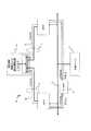
図1は本発明の実施の形態1にかかるマルチプロセッサシステム10を示すブロック図である。図1に示すように、本実施の形態のマルチプロセッサシステム10は、第1のCPU(以下、CPU1と称す)、第2のCPU(以下、CPU2と称す)、周辺回路である共有リソース3、相互排除制御ユニット4、共有バス5、ローカルバス6、7を有している。
FIG. 1 is a block diagram showing a
CPU1、CPU2は、共有バス5を介して共有リソース3にアクセスを行い、プログラムなどに基づいた各種の処理を実行する。相互排除制御ユニット4は、ローカルバス6、7を介して、それぞれCPU1、CPU2と接続され、共有リソース3に対するCPUのアクセス権の制御を行う部分である。本実施の形態における相互排除制御ユニット4の構成を図2に示す。図2に示すように実施の形態1の相互排除制御ユニット4は、アービタ41、相互排除変数レジスタ42を有している。 The
アービタ41は、複数のCPUが同時に相互排除制御ユニット4にアクセスした場合に、相互排除変数レジスタ42とCPUとの接続を調停する回路である。したがって、アービタ41には、ローカルバス6、7及び相互排除変数レジスタ42が接続されている。相互排除変数レジスタ42は、アドレスが割り付けられ、このアドレスを指定することによってCPU1、CPU2からアクセスされるレジスタである。相互排除変数レジスタ42は、CPU1、CPU2によってリード/ライトされる相互排除変数を保持する。
図3は、図1に示したマルチプロセッサシステムを更に詳細に示した図である。図3に示すように本実施の形態のマルチプロセッサシステムは、共有バス5の使用権を調停するアービタ8を更に有している。The
FIG. 3 is a diagram showing the multiprocessor system shown in FIG. 1 in more detail. As shown in FIG. 3, the multiprocessor system of the present embodiment further includes an
このように構成された本実施形態の相互排除制御の動作について以下に説明する。以下では、共有リソース3に対するアクセス権が空いている状態、つまりどのCPUも共有リソースに対してアクセス権を獲得していない場合の相互排除変数は"0"として説明する。CPU1あるいはCPU2によるアクセス権獲得の動作をフローチャートで示したものが図4に相当する。 The operation of the mutual exclusion control of the present embodiment configured as described above will be described below. In the following description, it is assumed that the mutual exclusion variable is “0” when the access right to the shared
相互排除変数レジスタ42が"0"を保持した状態で、CPU1が共有リソース3のアクセス権を要求する場合について説明する。CPU1が共有リソース3のアクセス権を要求する場合、ローカルバス6を介してCPU1が相互排除制御ユニット4に対してリード要求を出力する(図3、61および図4、S301参照)。このリード要求は、ローカルバス6を介して相互排除制御ユニット4へと与えられる。相互排除制御ユニット4では、相互排除変数レジスタ42の保持する値を読み出し、このリード値をCPU1へと出力する。相互排除変数レジスタ42が"0"を保持している状態であるとすれば、この"0"をCPU1へと出力する。 A case where the
CPU1では、リード値が"0"であるかどうかの判定が行われ、リード値が"0"であれば、相互排除制御ユニット4に対してライト要求を行う(図4、S302参照)。この時、CPU1がライト要求を行う値は、CPU1に固有の値(ここでは"ID1"とする)である。相互排除制御ユニット4は、CPU1からのライト要求にしたがって相互排除変数レジスタ42に"ID1"を書き込み(図4、S304参照)、CPU1がアクセス権を獲得した状態となる。図1に示す相互排除制御ユニット4によってアクセス権を獲得したCPU1は、アービタ8に対して共有バス5の使用を要求する。アービタ8によって共有バス5の使用が許可された場合、CPU1は、共有バス5を介して共有リソース3に対してアクセスし、必要な処理を実行する。 The
CPU1がアクセス権を獲得した状態で、CPU2が共有リソース3に対してアクセス権を要求する場合について説明する。CPU2が共有リソース3に対してアクセス権を要求する場合、CPU1がアクセス権を要求する場合と同様に、相互排除制御ユニット4に対してリード要求を出力する(図4、S301参照)。このリード要求は、ローカルバス71を介して相互排除制御ユニット4へと与えられる。相互排除制御ユニット4では、相互排除変数レジスタ42の保持する値"ID1"を読み出し、このリード値"ID1"をCPU2へと出力する。 A case where the CPU 2 requests the access right to the shared
CPU2では、リード値が"0"であるかどうかの判定が行われる(図4、S302参照)。ここでは、リード値は"0"ではないのでライト要求は出力されず、次の判定動作に移行する。CPU2は、リード値が"0"ではないため、リード値がCPU2の固有の値(ここでは"ID2"とする)と同じかどうかを判定する(図4、S303参照)。この場合、リード値は、"ID1"であるため、CPU2の"ID2"とは異なり、CPU2は、所定時間後に再びリード要求を行うなどのポーリング動作を行う。 The CPU 2 determines whether or not the read value is “0” (see S302 in FIG. 4). Here, since the read value is not “0”, the write request is not output, and the process proceeds to the next determination operation. Since the read value is not “0”, the CPU 2 determines whether or not the read value is the same as the unique value of the CPU 2 (here, “ID2”) (see S303 in FIG. 4). In this case, since the read value is “ID1”, unlike “ID2” of the CPU 2, the CPU 2 performs a polling operation such as making a read request again after a predetermined time.
また、CPUが実施するプログラムによっては、ある処理(ここでは処理Aと呼ぶ)を実行中に共有リソース3のアクセス権を一旦獲得した後、処理Aの終了前に他の処理(ここでは処理Bと呼ぶ)を行い、この処理Bが共有リソース3のアクセス権を獲得する場合がある。その後、処理Bの終了後にCPUは、再び処理Aの実行に復帰し、処理Aを終了させる必要がある。そこで、CPU1が処理Aの中で共有リソース3のアクセス権を獲得した状態で、CPU1が処理Bの中で共有リソース3のアクセス権を要求する場合について説明する。上記同様、CPU1が相互排除制御ユニット4に対してリード要求を出力する(図4、S301参照)。このリード要求は、ローカルバス6を介して相互排除制御ユニット4へと与えられる。相互排除制御ユニット4では、相互排除変数レジスタ42の保持する値"ID1"を読み出し、このリード値"ID1"をCPU1へと出力する。 Further, depending on the program executed by the CPU, after acquiring the access right of the shared
CPU1では、リード値が"0"であるかどうかの判定が行われ(図4、S302参照)、ここでは、リード値は"0"ではないので、次の判定動作に移行する。CPU1は、リード値がCPU1の"ID1"と同じかどうかを判定する(図4、S303参照)。この場合、リード値は、"ID1"であるため、CPU1の"ID1"と同じ値となる。したがって、CPU1は、相互排除制御ユニット4へ"ID1"のライト要求を行い、相互排除制御ユニット4では相互排除変数レジスタ42に"ID1"が書き込まれる(図4、S304参照)。CPU1は、共有リソース3に対するアクセス権を獲得し、アービタ8に対して共有バスの使用を要求する。アービタ8によって共有バスの使用が許可された場合、CPU1は、共有バス5を介して共有リソース3に対するアクセスを継続する。 The
このように実施の形態1では、共有バス5とは異なるローカルバス6、7を用いて各CPUと相互排除制御ユニット4を接続し、相互排除制御ユニット4内の相互排除制御レジスタ42から、共有リソース3の空き状態、あるいは共有リソース3にアクセス権を有するCPUの固有値(ID)を読み出すようにしている。そのため、共有リソース3に対するアクセス権を持たないCPUのポーリング動作によるアクセス要求は共有バス5を介して行われない。したがって、共有バス5は、ポーリング動作による影響を受けず、共有リソース3とアクセス権を持つCPUは、速やかにその処理を実行することが可能となる。 As described above, in the first embodiment, each CPU and the mutual
実施の形態2
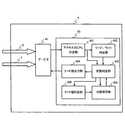
図5は、本発明の実施の形態2の相互排除制御ユニット4の構成を示すブロック図である。なお、マルチプロセッサシステム10としての構成は、図1と同一であるため、その詳細な説明は省略する。実施の形態2の相互排除制御ユニット4は、アービタ41、相互排除制御部43を有している。相互排除制御部43は、アクセス元CPU判定部431、リード/ライト判定部432、状態判定部433、リード値出力部434、状態保存部435、ライト値判定部436を有している。Embodiment 2
FIG. 5 is a block diagram showing a configuration of the mutual
アービタ41は、複数のCPUと相互排除制御部43の調停を行う回路である。相互排除制御部43は、アドレスが割り付けられ、このアドレスを指定することによってCPU1、CPU2からアクセスされる。相互排除制御部43は、共有リソース3に対してアクセスするCPUを制御し、相互排除を行う。アクセス元CPU判定部431は、アービタ41を介して与えられた信号からアクセス元のCPUを判定し、アクセス元のCPUを特定する。リード/ライト判定部432は、与えられた信号がリード要求なのか、ライト要求なのかを判定しその判定結果を出力する。状態判定部433は、アクセス元CPU判定部431、リード/ライト判定部432の出力に基づいて、状態保存部435から現在の状態を読み出す、あるいはライト値判定部436に対して状態保存部435に現在の状態に関する情報を書き込ませる信号を出力する。状態保存部435は、共有リソース3に対して現在アクセス権を有するCPUに関する情報を保持している。ライト値判定部436は、状態判定部433の出力に基づいて状態保存部435に対するライト値を判定し、状態保存部435に書き込む情報を決定する。上記した各部のより詳細な説明は、以下の動作説明において例を示しながら説明する。 The
図6は、本実施の形態の相互排除制御ユニット4の動作を示すフローチャートである。また、図7は、相互排除制御ユニット4の動作に伴う状態を示す状態遷移図である。また、図8はCPU1あるいはCPU2が行うアクセス権要求時のフローチャートである。以下、図5乃至図8を用いて本実施の形態の動作について説明する。なお、以下の動作では、図1に示すようにCPU1、CPU2が共有リソース3に対してローカルバス6、7を介してアクセス権を要求する場合を例として説明する。 FIG. 6 is a flowchart showing the operation of the mutual
まず、共有リソース3に対してアクセス権を保持するCPUが無く、共有リソースが空いた状態でCPU1が共有リソースに対してアクセス権を要求した場合を例にして説明する。CPU1は、共有リソース3に対してアクセス権を要求するため、相互排除制御ユニット4に対してローカルバス6を介してリード要求を行う(図8、S701参照)。このリード要求は、ローカルバス6、アービタ41を介して相互排除制御部43のアクセス元CPU判定部431へと与えられる。 First, a case will be described as an example where there is no CPU that holds the access right to the shared
アクセス元CPU判定部431では、どのCPUからの要求なのかが判定される(図6S1参照)。アクセス元のCPUは、図1のようにローカルバスが配置されたマルチプロセッサシステムであれば、どのローカルバスを介するアクセスかを判定するのみで可能であるため、即座に行うことが可能である。ここではCPU1からのアクセスであることが判定され、その情報は状態判定部433へと出力される。またCPU1からのリード要求はリード/ライト判定部432によってリード要求なのかライト要求なのかの判定が行われる(図6、S2参照)。ここではリード要求であるため、リード要求であることを示す情報が状態判定部433へと出力される。 The access source
状態判定部433では、CPU1からのリード要求に基づいて、状態保存部435に保存されている共有リソース3の現在の状態を確認する(図6、S4参照)。 The
上記したように状態保存部435は、共有リソース3に対して、現在アクセス権を有するCPUに関する情報を保持する部分である。CPU1、CPU2が存在する場合、共有リソース3に対するアクセス権の状態には、以下の3つの状態が存在する。
状態P0 共有リソース3が空いている状態
状態P1 共有リソース3に対するアクセス権をCPU1が獲得している状態
状態P2 共有リソース3に対するアクセス権をCPU2が獲得している状態As described above, the
State P0 State in which shared
ここでは、共通リソース3が空いている状態なので、状態保存部435は、状態P0を保持している。ここで、状態判定部433では、現在、共有リソース3は、空いている状態P0であり、CPU1によるリード要求であるためCPU1がアクセス権を獲得している状態の状態P1に状態保存部435の保持する状態を遷移させる(図6、S8及び図7参照)。その後、リード値出力部434に対して、CPU1に出力するリード値を指定する。 Here, since the
リード値出力部434は、状態判定部433によって指定されたリード値を、CPU1に出力する。ここでリード値出力部434が出力するリード値には、状態保存部435が保持していた状態、状態判定部433によって行われた動作によって、以下の3値が存在する。
リード値"0" 新たにアクセス権を獲得したことを示すリード値
リード値"1" アクセス権を既に獲得していたことを示すリード値
リード値"2" 他のCPUがアクセス権を獲得していたことを示すリード値The read
Read value “0” Read value indicating that a new access right has been acquired Read value “1” Read value indicating that an access right has already been acquired Read value “2” Another CPU has acquired the access right Lead value indicating that
ここでは、共有リソース3が空いていた状態P0から、CPU1が新たにアクセス権を獲得し、状態P1へと遷移したため新たにアクセス権を獲得した場合に相当するリード値"0"が出力される(図6、S8及び図7参照)。 Here, the read value “0” corresponding to the case where the access right is newly acquired because the
CPU1では、読み出したリード値がリード値"2"であるかどうかを判定している(図8、S702参照)。上記に説明したようにリード値"2"は、他のCPUが共有リソース3を獲得している状態であるため、リード値が"2"であればポーリング動作を行う。ここでは、リード値は"0"である。そのためCPU1は、CPU1自身がアクセス権を獲得したと判断し、アービタ8に対して共有バスの使用を要求する。アービタ8によって共有バスの使用が許可された場合、CPU1は、共有リソース3に対してアクセスを開始する。 The
次に、このCPU1がアクセス権を獲得した状態でCPU2が共有リソースに対してアクセス権を要求する場合を例にして説明する。CPU1がアクセス権を要求する時と同様に、CPU2は、相互排除制御ユニット4に対してリード要求を行う(図8、S701参照)。このリード要求は、ローカルバス7、アービタ41を介して相互排除制御部43のアクセス元CPU判定部431へと与えられ、どのCPUからの要求なのかが判定される(図6、S1参照)。また、リード/ライト判定部432によってリード要求なのかライト要求なのかの判定が行われる(図6、S3参照)。 Next, the case where the CPU 2 requests the access right to the shared resource in a state where the
状態判定部433では、CPU2からのリード要求に基づいて、状態保存部435に保存されている共有リソース3の現在の状態を確認する(図6、S6参照)。ここでは、状態保存部435は、上記した状態P1を保持している。アクセス元のCPU2と現在共有リソースに対するアクセス権を有するCPUが異なるため、状態判定部433では、状態保存部435が保持する状態P1を変更せずに、リード値"2"を出力するようにリード値出力部434に指定する(図6、S21及び図7参照)。 The
リード値出力部434は、リード値"2"を出力し、CPU2は入力されたリード値の判定を行う。リード値が"2"であるため、CPU2はCPU2以外のCPUが共有リソースに対するアクセス権を有するものと判断し、ポーリング動作を行う(図8、S702参照)。 The read
次に、CPU1がアクセス権を獲得した状態で、実施の形態1でも説明したように、処理Aを実行中に処理Bを行い、その後、処理Aに復帰するような場合について説明する。例えば処理Aから処理Bに移行した場合に、処理BにおいてCPU1が相互排除制御ユニット4に対してリード要求を出力する。このリード要求は、ローカルバス6を介して相互排除制御ユニット4へと与えられる。相互排除制御部43では、アクセス元CPU、リード/ライト要求の判定が行われる(図6、S1、S2参照)。 Next, a description will be given of a case in which the process B is performed while the process A is being executed and the process A is returned to the process A after the
状態判定部433では、CPU1からのリード要求に基づいて、状態保存部435に保存されている共有リソース3の現在の状態を確認する。ここでは、状態保存部435は、上記した状態P1を保持している。アクセス元のCPU1と現在共有リソースに対するアクセス権を有するCPUと同一のため、状態判定部433では、状態保存部435が保持する状態P1を変更せずに、リード値"1"を出力するようにリード値出力部434に指定する(図6、S14及び図7参照)。 The
CPU1では、リード値が"2"であるかどうかの判定が行われ、ここでは、リード値は"2"ではないので、CPU1は、共有リソース3に対するアクセス権を獲得したと判断し、アービタ8によって共有バスの使用が許可された場合、CPU1は、共有バス5を介して共有リソース3に対するアクセスを継続する(図8、S702参照)。 The
次に、CPU1がアクセス権を獲得した状態で、CPU1が共有リソース3に対するアクセス権を解放する場合について説明する。CPU1は、相互排除制御ユニット4に対してライト値と共にライト要求を出力する。ここで、CPUが相互排除制御ユニット4に出力するライト値には以下の2値が存在する。
ライト値"0" アクセス権を解放するライト値
ライト値"1" アクセス権を継続するライト値
なお、上記以外のライト値は、そもそもライト値として無効であるためライト値として出力しても相互排除制御ユニット4では無視される。Next, a case where the
Write value "0" Write value to release access right Write value "1" Write value to continue access right Note that write values other than the above are invalid as write values in the first place, so even if they are output as write values, they are mutually excluded It is ignored by the
ここでは、CPU1が共有リソース3を解放するため、CPU1はライト値"0"を伴うライト要求を出力する。このライト要求は、ローカルバス6を介して相互排除制御ユニット4へと与えられる。相互排除制御部43では、アクセス元CPU、リード/ライト要求の判定が行われる(図6、S1、S2参照)。 Here, since the
状態判定部433では、CPU1からのライト要求に基づいて、状態保存部435に保存されている共有リソース3の現在の状態を確認する(図6、S5参照)。ここでは、状態保存部435は、上記した状態P1を保持している。アクセス元のCPU1と現在共有リソースに対するアクセス権を有するCPUと同一であるため、ライト値判定部436によって、ライト値の判定が行われる(図6、S15参照)。ここで、仮にライト要求を出力してきたCPUが現在アクセス権を獲得しているCPU1と異なる場合(例えばCPU2である場合)は、誤ったライト要求であるため無視される(図6、S12参照)。ライト値判定部436では、ライト要求と共に入力されたライト値がライト値"0"であるのかライト値"1"であるのかの判定が行われる。ここでは、CPU1が共有リソースを解放するためライト値は"0"である。そのためライト値判定部436は状態保存部435が保持する状態P1を共有リソースが解放された状態P0に変更して処理を終了する(図6、S19及び図7参照)。 The
上記の例に示した動作において、例えば処理Aから処理B、その後処理Aに再帰するような動作では、処理Bから処理Aに再帰する時に、CPU1からライト値"1"のライト要求を出力する構成とすることも可能である。この場合、上記の共有リソース3を解放する動作と同様にライト値判定部436によってライト値が"1"と判定される。この場合ライト値が"1"であるので、状態は変更されずにCPU1が共有リソース3に対するアクセス権を継続する(図6、S20及び図7参照)。 In the operation shown in the above example, for example, in the operation of recurring from process A to process B and then to process A, the
以上は、CPU1が共有リソースに対するアクセス権を有する場合を中心に説明したが、図6乃至図8に示しているようにCPU2が共有リソースに対してアクセス権を有する場合にも基本的な動作は同様である。以下、表1、表2にCPU1、CPU2を有するマルチプロセッサシステムにおけるリード要求の動作、ライト要求の動作を示す。
本実施の形態においても、実施の形態1と同様に共有バス5とは異なるローカルバス6、7を用いて各CPUと相互排除制御ユニット4を接続し、相互排除制御ユニット4内の相互排除制御部43から、共有リソース3の空き状態を読み出すようにしている。そのため、共有バス5は、ポーリング動作による影響を受けず、共有リソース3とアクセス権を持つCPUは、速やかにその処理を実行することが可能となる。 Also in the present embodiment, each CPU and the mutual
さらに、本実施の形態による相互排除制御ユニット4は、状態判定部433、状態保存部435によって、現在、共有リソースに対するアクセス権を有するCPUを判定している。したがって、CPU側での命令実行数の増加によるオーバーヘッドを軽減することが可能となる。本実施の形態では、相互排除制御部43が、共有リソース3が空いている状態か、他のCPUがアクセス権を有している状態かあるいはアクセス権を要求したCPU自身がアクセス権を有している状態かを出力している。そのためCPU側では図8に示すように他のCPUが使用しているかどうかを判定するのみでアクセス権の有無が判定できるため命令実行数のオーバーヘッドを削減することが可能である。また、本実施の形態では、複数のCPUがそれぞれ固有値を有する必要が無く、仮に持っていたとしてもリード要求、ライト要求時に、自CPUを示せればよいだけであるため上記の命令実行のオーバーヘッドを削減することが可能となる。 Furthermore, the mutual
実施の形態3
図9は、本発明の実施の形態3の相互排除制御ユニット4の構成を示すブロック図である。なお、マルチプロセッサシステム10としての構成は、図1と同一であるため、その詳細な説明は省略する。本実施の形態は、アービタ41、相互排除変数レジスタ42及び相互排除制御部43を有している。アービタ41は、相互排除変数レジスタ42及び相互排除制御部43とCPUのアクセスを調停する。相互排除変数レジスタ42は、実施の形態1と同様の相互排除変数レジスタ42であり、共有リソース3の空き状態、あるいは共有リソース3に対するアクセス権を獲得しているCPUのCPU毎の固有値を保持する。相互排除制御部43は、実施の形態2と同様の相互排除制御部43であり、共有リソース3が空いている状態か、他のCPUがアクセスしている状態かあるいはアクセスを要求したCPU自身がアクセスしている状態かを出力する。
FIG. 9 is a block diagram showing a configuration of the mutual
このように構成することで、CPU毎の固有値を有するCPU、固有値を有さないCPUなどが並存するマルチプロセッサシステムでも共有リソース3のアクセス権を適切に設定することが可能となる。 With this configuration, it is possible to appropriately set the access right of the shared
実施の形態4
図10は、本発明の実施の形態4のマルチプロセッサシステム20の構成を示すブロック図である。実施の形態1乃至3では、相互排除制御ユニット4内に、アービタ41が内蔵される構成について説明したが、本実施の形態ではローカルバス用のアービタ9が相互排除制御ユニット4とは別に構成される。この場合、CPU毎のローカルバス6および7がそれぞれ相互排除制御ユニットに接続されるのではなく、相互排除制御ユニット4に接続するためのローカルバス6'が共通に形成される。アービタ9は、複数のCPUからの相互排除制御ユニット4に対するアクセス要求を調停し、いずれかのCPUに対してローカルバス6'の使用を許可する。
ローカルバスの使用が可能となったCPUの相互排除制御レジスタ42に対する動作は、実施の形態1と同様であるため、その詳細な説明は割愛する。
FIG. 10 is a block diagram showing a configuration of the
Since the operation on the mutual exclusion control register 42 of the CPU that can use the local bus is the same as that of the first embodiment, the detailed description thereof is omitted.
実施の形態5
図11は、本発明の実施の形態5の相互排除制御ユニットの構成を示す図である。本実施の形態は、実施の形態4で説明したローカルバス6'が共通して形成されている場合に、実施の形態2において説明した相互排除制御ユニット4を適用した場合に相当する。本実施の形態では、アクセス元CPU判定部431に対し、ローカルバス用のアービタ9から、ローカルバス6'を使用しているCPUに関する情報を与えることが可能である。あるいは、ローカルバス6'を使用するCPUがCPU固有の識別情報と共にローカルバスを介してリード要求などを送信し、アクセス元CPU判定部431によって、その固有情報からアクセス元CPUを判定しても良い。
その後の、状態判定、状態保存などの動作は実施の形態2と、同様であるため詳細な説明は、割愛する。
FIG. 11 is a diagram showing the configuration of the mutual exclusion control unit according to the fifth embodiment of the present invention. The present embodiment corresponds to the case where the mutual
Subsequent operations such as state determination and state storage are the same as those in the second embodiment, and a detailed description thereof will be omitted.
実施の形態6
図12は、本発明の実施の形態6の相互排除制御ユニット4の構成を示すブロック図である。本実施の形態は、実施の形態4で説明したローカルバス6'が共通して形成されている場合に、実施の形態3において説明した相互排除制御ユニット4を適用した場合に相当する。詳細な動作や構成は実施の形態1および2と同様であるため割愛する。
FIG. 12 is a block diagram showing a configuration of the mutual
以上、実施の形態に基づいて詳細に説明したが、本発明は上記した実施の形態に限定されず本発明の主旨を変更しない限り種々の変形が可能である。例えば、実施の形態では1つの共有リソースの例を用いて示したが、複数の共有リソースを有する場合でも、1つの相互排除制御ユニット内に各共通リソースに対応する相互排除変数レジスタ、相互排除制御部を用意することで対応が可能である。 As mentioned above, although it demonstrated in detail based on embodiment, this invention is not limited to above-described embodiment, A various deformation | transformation is possible unless it changes the main point of this invention. For example, in the embodiment, an example of one shared resource is used. However, even when a plurality of shared resources are provided, a mutual exclusion variable register corresponding to each common resource and mutual exclusion control are included in one mutual exclusion control unit. It is possible to respond by preparing a part.
CPU1、CPU2 CPU
3 共有リソース
4 相互排除制御ユニット
5 共有バス
6、6'、7、61、71 ローカルバス
8 アービタ
10、20 マルチプロセッサシステム
9、41 アービタ
42 相互排除変数レジスタ
43 相互排除制御部
431 アクセス元CPU判定部
432 リード/ライト判定部
433 状態判定部
434 リード値出力部
435 状態保存部
436 ライト値判定部CPU1, CPU2 CPU
3
Claims (12)
Translated fromJapanese前記複数のプロセッサと前記共有リソースを接続する共有バスと、
前記複数のプロセッサのうち、いずれのプロセッサが前記共有リソースに対するアクセス権を獲得しているかを示す識別情報を保持する相互排除制御ユニットと、
前記相互排除制御ユニットと前記複数のプロセッサを接続するローカルバスと、を備え、
前記相互排除制御ユニットは、
前記複数のプロセッサのうち、前記共有リソースに対するアクセス権を既に獲得しているプロセッサを識別する情報を記憶する状態保存部と、
前記複数のプロセッサのうち、前記共有リソースに対するアクセス権を要求しているプロセッサを特定するアクセス元判定部と、
前記状態保存部により記憶された前記アクセス権を既に獲得しているプロセッサと、前記アクセス元判定部により特定された前記アクセス権を要求しているプロセッサと、を比較し、その比較結果に基づいて、前記アクセス権を要求しているプロセッサに対して前記共有リソースに対するアクセス権があるか否かを示す情報を出力する状態判定部と、を有するマルチプロセッサシステム。A multiprocessor system having a plurality of processors and a shared resource accessible by the plurality of processors,
A shared bus connecting the plurality of processors and the shared resource;
A mutual exclusion control unit that holds identification information indicating which of the plurality of processors has acquired an access right to the shared resource;
Anda local bus connecting said plurality of processors and the mutual exclusion controlunit,
The mutual exclusion control unit includes:
A state storage unit that stores information for identifying a processor that has already acquired an access right to the shared resource among the plurality of processors;
Of the plurality of processors, an access source determination unit that identifies a processor that requests access rights to the shared resource;
The processor that has already acquired the access right stored by the state storage unit is compared with the processor that has requested the access right specified by the access source determination unit, and based on the comparison result And a state determination unit that outputs information indicating whether the processor requesting the access right has an access right to the shared resource .
前記複数のプロセッサのうち、前記共有リソースに対するアクセス権を要求しているプロセッサが前記共有リソースに対するアクセス権を既に獲得しているプロセッサと異なる場合に、前記共有リソースに対するアクセス権を要求しているプロセッサに対してアクセス不可を示す信号を出力することを特徴とする請求項1乃至5のいずれか1項に記載のマルチプロセッサシステム。The mutual exclusion control unit includes:
Among the plurality of processors, a processor the processorrequesting access to the shared resource is different from the processorwhich already won access to the shared resource,requesting access to the shared resource multiprocessor system according to any one of claims1 to5, characterized in that outputs a signal indicating the inaccessible respect.
前記複数のプロセッサのそれぞれに対応して設定された固有値を保持するレジスタを有することを特徴とする請求項1乃至6のいずれか1項に記載のマルチプロセッサシステム。The multiprocessor system according to anyone of claims1 to6 , wherein the mutual exclusion control unit further includes a register that holds an eigenvalue set corresponding to each of the plurality of processors.
前記複数のプロセッサのうち前記共有リソースに対してアクセス権を既に獲得しているプロセッサの情報を記憶し、
前記共有リソースに対してアクセス権を要求しているプロセッサを特定し、
前記アクセス権を要求しているプロセッサと、前記アクセス権を既に獲得しているプロセッサと、を比較し、
その比較結果に基づいて、前記アクセス権を要求しているプロセッサに対して前記共有リソースに対するアクセス権があるか否かを示す情報を出力することを特徴とするアクセス権設定方法。An access right setting method for setting an access right to one of the plurality of processors with respect to a shared resource shared by a plurality of processors,
Storingpreviously information processorthat has acquired the rightto access to the shared resource among the plurality of processors,
Identify the processorrequesting access to the shared resource,
Comparing aprocessor requesting theaccess,theprocessor has acquired the access rightalready a
Based onthe comparison result, the access right setting method and outputtinginformation indicating whether there is accessto the shared resource to the processorrequestingthe access.
Priority Applications (2)
| Application Number | Priority Date | Filing Date | Title |
|---|---|---|---|
| JP2007132461AJP4874165B2 (en) | 2006-07-07 | 2007-05-18 | Multiprocessor system and access right setting method in multiprocessor system |
| US11/822,335US20080010643A1 (en) | 2006-07-07 | 2007-07-05 | Multiprocessor system and access right setting method in the multiprocessor system |
Applications Claiming Priority (3)
| Application Number | Priority Date | Filing Date | Title |
|---|---|---|---|
| JP2006188364 | 2006-07-07 | ||
| JP2006188364 | 2006-07-07 | ||
| JP2007132461AJP4874165B2 (en) | 2006-07-07 | 2007-05-18 | Multiprocessor system and access right setting method in multiprocessor system |
Publications (2)
| Publication Number | Publication Date |
|---|---|
| JP2008033893A JP2008033893A (en) | 2008-02-14 |
| JP4874165B2true JP4874165B2 (en) | 2012-02-15 |
Family
ID=38920459
Family Applications (1)
| Application Number | Title | Priority Date | Filing Date |
|---|---|---|---|
| JP2007132461AExpired - Fee RelatedJP4874165B2 (en) | 2006-07-07 | 2007-05-18 | Multiprocessor system and access right setting method in multiprocessor system |
Country Status (2)
| Country | Link |
|---|---|
| US (1) | US20080010643A1 (en) |
| JP (1) | JP4874165B2 (en) |
Families Citing this family (9)
| Publication number | Priority date | Publication date | Assignee | Title |
|---|---|---|---|---|
| US7908077B2 (en) | 2003-06-10 | 2011-03-15 | Itt Manufacturing Enterprises, Inc. | Land use compatibility planning software |
| US7965227B2 (en) | 2006-05-08 | 2011-06-21 | Era Systems, Inc. | Aircraft tracking using low cost tagging as a discriminator |
| CN101901547A (en)* | 2010-07-21 | 2010-12-01 | 浙江工业大学 | A variable lane adaptive control method |
| US8918594B2 (en) | 2010-11-16 | 2014-12-23 | Micron Technology, Inc. | Multi-interface memory with access control |
| DE102011078630A1 (en)* | 2011-07-05 | 2013-01-10 | Robert Bosch Gmbh | Method for setting up a system of technical units |
| US9152474B2 (en)* | 2014-01-20 | 2015-10-06 | Netapp, Inc. | Context aware synchronization using context and input parameter objects associated with a mutual exclusion lock |
| KR102416465B1 (en) | 2015-11-30 | 2022-07-04 | 삼성전자주식회사 | Data Processing System of Effectively Managing Shared Resource |
| CN111367467B (en)* | 2018-12-26 | 2022-11-04 | 浙江宇视科技有限公司 | A storage resource mounting method, device, server and distributed system |
| CN113190496B (en)* | 2021-04-23 | 2023-12-26 | 深圳市汇顶科技股份有限公司 | Kernel communication method, device, chip, electronic equipment and storage medium |
Family Cites Families (21)
| Publication number | Priority date | Publication date | Assignee | Title |
|---|---|---|---|---|
| US5669002A (en)* | 1990-06-28 | 1997-09-16 | Digital Equipment Corp. | Multi-processor resource locking mechanism with a lock register corresponding to each resource stored in common memory |
| JPH07113909B2 (en)* | 1992-11-27 | 1995-12-06 | 工業技術院長 | Parallel computer |
| US5553298A (en)* | 1994-04-14 | 1996-09-03 | Merryman, Deceased; Philip I. | Method and apparatus for mutual exclusion in self-directed distributed systems |
| WO1997005550A1 (en)* | 1995-07-27 | 1997-02-13 | Intel Corporation | Protocol for arbitrating access to a shared memory area using historical state information |
| CA2213371C (en)* | 1996-08-28 | 2003-01-28 | Hitachi, Ltd. | Process executing method and resource accessing method in computer system |
| US6886162B1 (en)* | 1997-08-29 | 2005-04-26 | International Business Machines Corporation | High speed methods for maintaining a summary of thread activity for multiprocessor computer systems |
| JPH11203253A (en)* | 1998-01-09 | 1999-07-30 | Matsushita Electric Ind Co Ltd | Exclusive access control method for shared resources |
| US6499048B1 (en)* | 1998-06-30 | 2002-12-24 | Sun Microsystems, Inc. | Control of multiple computer processes using a mutual exclusion primitive ordering mechanism |
| US7143410B1 (en)* | 2000-03-31 | 2006-11-28 | Intel Corporation | Synchronization mechanism and method for synchronizing multiple threads with a single thread |
| US6782440B2 (en)* | 2000-07-26 | 2004-08-24 | T.N.S. Holdings, Inc. | Resource locking and thread synchronization in a multiprocessor environment |
| US6826754B1 (en)* | 2000-09-29 | 2004-11-30 | International Business Machines Corporation | Method for eliminating or reducing hang conditions in computer systems |
| US6757769B1 (en)* | 2000-11-28 | 2004-06-29 | Emc Corporation | Cooperative lock override procedure |
| US20040039884A1 (en)* | 2002-08-21 | 2004-02-26 | Qing Li | System and method for managing the memory in a computer system |
| US7383368B2 (en)* | 2003-09-25 | 2008-06-03 | Dell Products L.P. | Method and system for autonomically adaptive mutexes by considering acquisition cost value |
| US7644409B2 (en)* | 2004-06-04 | 2010-01-05 | Sun Microsystems, Inc. | Techniques for accessing a shared resource using an improved synchronization mechanism |
| WO2006030650A1 (en)* | 2004-09-16 | 2006-03-23 | Nec Corporation | Information processing device having a plurality of processing units sharing a resource |
| ATE555437T1 (en)* | 2004-11-26 | 2012-05-15 | Ibm | MULTIPROCESSOR SYSTEM AND METHOD FOR EXCLUSIVE CONTROL THEREOF |
| US7275121B1 (en)* | 2005-04-05 | 2007-09-25 | Nvidia Corporation | System and method for hardware assisted resource sharing |
| JP2007058493A (en)* | 2005-08-24 | 2007-03-08 | Internatl Business Mach Corp <Ibm> | Multiprocessor system and its exclusive control method |
| US7421529B2 (en)* | 2005-10-20 | 2008-09-02 | Qualcomm Incorporated | Method and apparatus to clear semaphore reservation for exclusive access to shared memory |
| US7827559B1 (en)* | 2006-04-24 | 2010-11-02 | Real-Time Innovations, Inc. | Framework for executing multiple threads and sharing resources in a multithreaded computer programming environment |
- 2007
- 2007-05-18JPJP2007132461Apatent/JP4874165B2/ennot_activeExpired - Fee Related
- 2007-07-05USUS11/822,335patent/US20080010643A1/ennot_activeAbandoned
Also Published As
| Publication number | Publication date |
|---|---|
| JP2008033893A (en) | 2008-02-14 |
| US20080010643A1 (en) | 2008-01-10 |
Similar Documents
| Publication | Publication Date | Title |
|---|---|---|
| JP4874165B2 (en) | Multiprocessor system and access right setting method in multiprocessor system | |
| EP1938190B1 (en) | Method and apparatus to clear semaphore reservation | |
| US20080126643A1 (en) | Semiconductor circuit | |
| US6792497B1 (en) | System and method for hardware assisted spinlock | |
| US7640315B1 (en) | Implementing locks in a distributed processing system | |
| JP6005392B2 (en) | Method and apparatus for routing | |
| US8458411B2 (en) | Distributed shared memory multiprocessor and data processing method | |
| US20030033489A1 (en) | Semaphore management circuit | |
| JP2007219816A (en) | Multiprocessor system | |
| CN114780248A (en) | Resource access method, device, computer equipment and storage medium | |
| JP5213485B2 (en) | Data synchronization method and multiprocessor system in multiprocessor system | |
| JP4818820B2 (en) | Bus system, bus slave and bus control method | |
| US7765383B2 (en) | Data processing unit and data processing apparatus using data processing unit | |
| JPH0348962A (en) | Bus lock control method | |
| JPH02244252A (en) | One-chip multiprocessor containing bus arbiter and comparator | |
| JPH11203253A (en) | Exclusive access control method for shared resources | |
| JP4370227B2 (en) | Processor | |
| JP2009187327A (en) | Processing request arbitration method of information communication method, its system and control program therefor | |
| JP2010186259A (en) | Semiconductor integrated circuit device and operation method of semiconductor integrated circuit device | |
| JP2825589B2 (en) | Bus control method | |
| US8301845B2 (en) | Access control method and computer system | |
| JP3187117B2 (en) | One-chip microcomputer with built-in multiprocessor | |
| JP3219422B2 (en) | Cache memory control method | |
| JPH0581211A (en) | Communication method between processors | |
| JPS6235960A (en) | Exclusive control information control system |
Legal Events
| Date | Code | Title | Description |
|---|---|---|---|
| A621 | Written request for application examination | Free format text:JAPANESE INTERMEDIATE CODE: A621 Effective date:20100416 | |
| A977 | Report on retrieval | Free format text:JAPANESE INTERMEDIATE CODE: A971007 Effective date:20110714 | |
| A131 | Notification of reasons for refusal | Free format text:JAPANESE INTERMEDIATE CODE: A131 Effective date:20110816 | |
| A521 | Written amendment | Free format text:JAPANESE INTERMEDIATE CODE: A523 Effective date:20111014 | |
| TRDD | Decision of grant or rejection written | ||
| A01 | Written decision to grant a patent or to grant a registration (utility model) | Free format text:JAPANESE INTERMEDIATE CODE: A01 Effective date:20111101 | |
| A01 | Written decision to grant a patent or to grant a registration (utility model) | Free format text:JAPANESE INTERMEDIATE CODE: A01 | |
| A61 | First payment of annual fees (during grant procedure) | Free format text:JAPANESE INTERMEDIATE CODE: A61 Effective date:20111122 | |
| FPAY | Renewal fee payment (event date is renewal date of database) | Free format text:PAYMENT UNTIL: 20141202 Year of fee payment:3 | |
| R150 | Certificate of patent or registration of utility model | Ref document number:4874165 Country of ref document:JP Free format text:JAPANESE INTERMEDIATE CODE: R150 Free format text:JAPANESE INTERMEDIATE CODE: R150 | |
| S531 | Written request for registration of change of domicile | Free format text:JAPANESE INTERMEDIATE CODE: R313531 | |
| R350 | Written notification of registration of transfer | Free format text:JAPANESE INTERMEDIATE CODE: R350 | |
| LAPS | Cancellation because of no payment of annual fees |