JP4873997B2 - Equipment storage rack and equipment storage room air conditioning system - Google Patents
Equipment storage rack and equipment storage room air conditioning systemDownload PDFInfo
- Publication number
- JP4873997B2 JP4873997B2JP2006146697AJP2006146697AJP4873997B2JP 4873997 B2JP4873997 B2JP 4873997B2JP 2006146697 AJP2006146697 AJP 2006146697AJP 2006146697 AJP2006146697 AJP 2006146697AJP 4873997 B2JP4873997 B2JP 4873997B2
- Authority
- JP
- Japan
- Prior art keywords
- cold air
- air
- equipment storage
- wind pressure
- information processing
- Prior art date
- Legal status (The legal status is an assumption and is not a legal conclusion. Google has not performed a legal analysis and makes no representation as to the accuracy of the status listed.)
- Active
Links
Images


Landscapes
- Air-Flow Control Members (AREA)
Description
Translated fromJapanese本発明は、電算機等の情報処理機器を収容する機器収容ラックおよび機器収容室用空調システムに関する。より詳しくは、データセンターまたは電算センター等(以下、これらをまとめて「データセンター」と称す)において、機器収容室に設置された機器収容ラックに収容された情報処理機器を冷却するために、空調装置からの冷気をラック本体に効率よく導入することのできる機器収容ラックおよび機器収容室用空調システムに関する。 The present invention relates to a device storage rack for storing information processing equipment such as a computer and an air conditioning system for a device storage room. More specifically, in a data center or a computer center (hereinafter collectively referred to as a “data center”), an air conditioner is used to cool information processing equipment accommodated in an equipment accommodation rack installed in the equipment accommodation room. The present invention relates to an equipment storage rack and an equipment storage room air conditioning system capable of efficiently introducing cool air from an apparatus into a rack body.
データセンター等の機器収容室に収容されるコンピュータまたは通信機器等の情報処理機器は、その発熱対策が重要であり、情報処理機器の温度上昇はシステムトラブルに直結する。このため、情報処理機器の冷却には専用の空調システムが用いられる(例えば、特許文献1を参照)。
例えば上記特許文献1に開示されている空調システムは、情報処理機器を収容するラックが置かれた室内の床が二重床となっている。この二重床の間には空間があり、空調機から供給される冷気はこの空間を通って上記ラックの下側からラック内部に導入される。ラック内部に導入された冷気は、ラック内の情報処理機器を冷却した後、ラックの上方(または背面方向)に放出される。この放出される空気は、各ラックの上方を通って空調機の吸入口に吸い込まれ、再び冷気となって上記二重床の間の空間に吹き出される。 For example, in the air conditioning system disclosed in Patent Document 1, the indoor floor on which a rack that accommodates information processing equipment is placed is a double floor. There is a space between the double floors, and the cold air supplied from the air conditioner is introduced into the rack from the lower side of the rack through the space. The cool air introduced into the rack cools the information processing equipment in the rack, and then is discharged upward (or in the back direction) of the rack. The discharged air passes through the top of each rack and is sucked into the air inlet of the air conditioner, and is again cooled and blown into the space between the double floors.
ところで、近年、データセンター等で使用している情報処理機器の使用時における発熱量はより大きくなってきている。したがって、上記空調システムにおいては、ラック上段の情報処理機器を効率的に冷却することが課題となっており、当該課題を解決するべく空調システムが提案されている。
上記特許文献2には、通路を挟んだ両側のラックの上面間(通路上方)に遮蔽板を設け、さらに通路の両端に壁体が配された空調システムが開示されている。この空調システムでは、上記両側のラック、遮蔽板および壁体で囲まれる空間が外部と遮断されており、この空間に床面から冷気が供給される。この場合、ラックは、通路と対向する側の面から冷気をラック内に導入することができるので、ラックの上段の情報処理機器をより効率的に冷却することができる。 Patent Document 2 discloses an air conditioning system in which a shielding plate is provided between the upper surfaces of racks on both sides sandwiching a passage (above the passage), and walls are disposed at both ends of the passage. In this air conditioning system, the space surrounded by the racks, shielding plates and walls on both sides is shut off from the outside, and cold air is supplied to the space from the floor. In this case, since the rack can introduce cool air into the rack from the surface facing the passage, the information processing device on the upper stage of the rack can be cooled more efficiently.
しかしながら、従来の空調システムにおいて、空調機からの冷気の供給能力は、ラックまたは情報処理機器に取り付けられたファンによる排気能力よりも大きく設定されている。これは、外気温の変化および情報処理機器の発熱量などの様々な条件の変化に対して、情報処理機器の冷却能力が不足することがないように冷気の供給能力が設定されているためである。したがって、上記のように、ラック、遮蔽板および壁体で囲まれる空間が外部と遮断された空調システムでは、すなわち上記ファンに対して排気能力を上回る過大な負荷がかかり、当該ファンの故障に繋がる場合がある。 However, in the conventional air conditioning system, the supply capacity of the cold air from the air conditioner is set larger than the exhaust capacity of the fan attached to the rack or the information processing device. This is because the cooling air supply capacity is set so that the cooling capacity of the information processing equipment does not become insufficient with respect to changes in various conditions such as changes in the outside air temperature and heat generation of the information processing equipment. is there. Therefore, as described above, in the air conditioning system in which the space surrounded by the rack, the shielding plate, and the wall is blocked from the outside, that is, an excessive load exceeding the exhaust capacity is applied to the fan, leading to the failure of the fan. There is a case.
上記課題を解決するために、本発明の第1の形態においては、情報処理機器を収容する機器収容ラックであって、情報処理機器を支持するラック本体と、冷気の風圧を保って、冷気をラック本体に導入する冷気導入部と、冷気導入部に配され、冷気導入部内の風圧を排気側に開放する風圧調整部とを備える機器収容ラックが提供される。これにより、ラック本体における冷気が導入される側と情報処理機器を冷却した空気が排気される排気側とを遮断する冷気導入部を設けた場合でも、ラック本体または情報処理機器に取り付けられたファンに対して排気能力を上回る過大な負荷がかかることがなく、当該ファンの故障を防ぐことができる。 In order to solve the above-described problem, in the first embodiment of the present invention, an equipment storage rack for storing information processing equipment, the rack body supporting the information processing equipment, and maintaining the wind pressure of the cool air, There is provided an equipment storage rack that includes a cold air introduction section that is introduced into the rack body, and a wind pressure adjusting section that is disposed in the cold air introduction section and opens the wind pressure in the cold air introduction section to the exhaust side. As a result, even when a cool air introduction section is provided to block the cool air introduction side of the rack body from the exhaust side from which the air that has cooled the information processing equipment is exhausted, the fan attached to the rack body or the information processing equipment In contrast, an excessive load exceeding the exhaust capacity is not applied, and failure of the fan can be prevented.
上記機器収容ラックにおいて、冷気導入部は、ラック本体における冷気が導入される側の面を排気側から隔てる天面および側面を有し、冷気は冷気導入部の下側から導入され、風圧調整部は、冷気導入部の天面または側面の上部に設けられて、冷気導入部の下側から導入される冷気の風圧を排気側に開放してもよい。これにより、風圧調整部が冷気導入部の下部に設けられた場合と比べて、冷気導入部の下側から導入される冷気がラック本体に導入されるのを妨げることなく、冷気導入部内の風圧の上昇を抑えることができる。 In the equipment storage rack, the cold air introduction portion has a top surface and a side surface that separates a surface of the rack body from which the cold air is introduced from the exhaust side, and the cold air is introduced from the lower side of the cold air introduction portion, and the wind pressure adjustment portion May be provided on the top surface or the side surface of the cold air introduction unit to release the wind pressure of the cold air introduced from the lower side of the cold air introduction unit to the exhaust side. As a result, compared with the case where the wind pressure adjusting unit is provided at the lower part of the cold air introducing unit, the wind pressure in the cold air introducing unit is prevented without preventing the cold air introduced from the lower side of the cold air introducing unit from being introduced into the rack body. Can be suppressed.
また、上記機器収容ラックにおいて、風圧調整部は、冷気導入部内の風圧が排気側の気圧よりも所定値以上高い場合に開くフラップを含んでもよい。これにより、上記機器収容ラックは、冷気導入部内の風圧の上昇を抑えて一定に保つことができるので、ラック本体または情報処理機器に取り付けられたファンに対して排気能力を上回る過大な負荷がかかることを防ぐことができる。 Further, in the equipment storage rack, the wind pressure adjustment unit may include a flap that opens when the wind pressure in the cold air introduction unit is higher than the pressure on the exhaust side by a predetermined value or more. Thereby, since the said apparatus accommodation rack can suppress the raise of the wind pressure in a cold air introducing | transducing part, and can keep it constant, the excessive load exceeding an exhaust_gas | exhaustion capacity will be applied with respect to the fan attached to the rack main body or information processing equipment. Can be prevented.
また、上記機器収容ラックにおいて、風圧調整部は、スリットまたはノズルの少なくとも一方を含んでもよい。これにより、上記機器収容ラックは、簡易な構成により冷気導入部内の風圧の上昇を抑えることができる。 Moreover, in the said equipment storage rack, a wind pressure adjustment part may include at least one of a slit or a nozzle. Thereby, the said apparatus accommodation rack can suppress the raise of the wind pressure in a cold air introduction part by simple structure.
また、上記機器収容ラックにおいて、ラック本体は、冷気導入部から冷気が導入される側の面の少なくとも一部に冷気の導入を遮断するブランクパネルを有し、風圧調整部は、ブランクパネルに設けられてもよい。これにより、ラック本体における情報処理機器が収容されている部分にだけ冷気を導入することができる。また、風圧調整部がブランクパネルに設けられているので、ラック本体にブランクパネルが設けられたことで冷気導入部内の風圧の急激な上昇を抑えることができる。 Further, in the equipment housing rack, the rack body has a blank panel for blocking the introduction of the cold air on at least a part of the surface where the cold air is introduced from the cold air introduction portion, and the wind pressure adjusting portion is provided on the blank panel. May be. Thereby, cold air can be introduced only into the portion of the rack body in which the information processing device is accommodated. Moreover, since the wind pressure adjustment part is provided in the blank panel, the rapid rise of the wind pressure in the cold air introduction part can be suppressed by providing the blank panel in the rack body.
また、上記機器収容ラックは、冷気導入部内と外部とを利用者が出入りするための出入扉をさらに備え、風圧調整部は、出入扉に設けられてもよい。 Moreover, the said equipment storage rack is further equipped with the entrance / exit door for a user to enter / exit the inside and outside of a cool air introduction part, and a wind pressure adjustment part may be provided in an entrance / exit door.
本発明の第2の形態においては、情報処理機器を収容する機器収容ラックと、空調装置から出力された冷気を機器収容ラックに送風する送風路とを備え、機器収ラックは、情報処理機器を支持するラック本体、送風路から送付された冷気の風圧を保って、冷気をラック本体に導入する冷気導入部、および、冷気導入部に配され、冷気導入部内の風圧を排気側に開放する風圧調整部を有する機器収容室用空調システムが提供される。 According to a second aspect of the present invention, the apparatus storage rack includes an apparatus storage rack that stores information processing equipment and an air passage that blows cool air output from the air conditioner to the equipment storage rack. Maintaining the wind pressure of the cool air sent from the rack body and the air flow path, the cool air introduction section for introducing the cool air into the rack body, and the wind pressure that is arranged in the cool air introduction section and opens the wind pressure in the cool air introduction section to the exhaust side An air conditioning system for an equipment storage room having an adjustment unit is provided.
なお、上記発明の概要は、本発明の必要な特徴の全てを列挙したものではなく、これらの特徴群のサブコンビネーションもまた、発明となりうる。 The summary of the invention does not enumerate all necessary features of the present invention, and sub-combinations of these feature groups can also be the invention.
以下、発明の実施の形態を通じて本発明を説明するが、以下の実施形態は特許請求の範囲にかかる発明を限定するものではなく、また実施形態の中で説明されている特徴の組み合わせの全てが発明の解決手段に必須であるとは限らない。 Hereinafter, the present invention will be described through embodiments of the invention. However, the following embodiments do not limit the invention according to the scope of claims, and all combinations of features described in the embodiments are included. It is not necessarily essential for the solution of the invention.
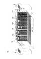
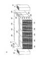
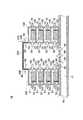
図1は、本発明の実施形態に係る機器収容室用空調システム10の外観を示す斜視図である。図2は、機器収容室用空調システム10の一部を透視した斜視図である。図3は、機器収容ラック20の通路43と直交する面における概略断面図、および、フラップ300の拡大図である。図1から図3において、機器収容室用空調システム10は建物の室内に配されており、不図示の壁および天井で囲まれている。図1に示すように、機器収容室用空調システム10は、機器収容ラック20および機器収容ラック20の両側に設けられた空調装置30とを備える。また、図2に示すように、機器収容ラック20および空調装置30が設置されている床は二重床40となっており、二重床40の間には内部空間41がある。 FIG. 1 is a perspective view showing an appearance of an
機器収容ラック20は、複数のラック本体100、冷気導入部200、出入扉230を有する。複数のラック本体100は、床面に対して鉛直な一の側面に冷気導入口101を有し、この冷気導入口101を有する側面が対向するように2列に並んで配される。また、これら複数のラック本体100は、冷気導入口101を有する側面の裏側に位置する側面に熱気排出口102を有する。 The
上記のように2列に並んで配された複数のラック本体100は、その列と列との間に間隔を有する。後述するように、複数のラック本体100はそれぞれ情報処理機器50を収容するが、上記の間隔は、この情報処理機器50の管理担当者等の利用者の通路43である。したがって、通路43は、利用者が通行またはラック本体100の前で作業するのに十分な広さであることが好ましい。 The plurality of rack
図3に示すように、複数のラック本体100は、それぞれ内部で複数の段(本実施形態では4段)に分割されており、各段は、それぞれ通路43側に冷気導入口101を有し、冷気導入口101を有する側と情報処理機器50を挟んで反対側に熱気排出口102を有する。また、ラック本体100の各段には空冷ファン51を備えた情報処理機器50が収容されており、情報処理機器50は、各段の底板に固定されて支持される。ここで、機器収容室用空調システム10の運転時において、各段の情報処理機器50の空冷ファン51は、冷気導入口101の側から熱気排出口102の側に空気の流れを作るように回転する。 As shown in FIG. 3, the plurality of rack
冷気導入部200は、側面210および天面220を有し、通路43の上方に配されて上記複数のラック本体100の上面に固定される。この冷気導入部200の側面210には、フラップ300が配される。 The cold
図3に示すように、フラップ300は、開口部310、把持部320および開閉部330を有し、上記のように冷気導入部200の側面210に配される。開閉部330は、例えば樹脂またはゴム等で形成されたシート状または板状の部材であり、把持部320に接着またはビス留め等の方法で固定される。上記フラップ300は、風圧調整部の一の形態である。 As shown in FIG. 3, the
出入扉230は、通路43の両端に配されて、上記複数のラック本体100のそれぞれの列の両端に位置するラック本体100の側面に固定される。上記利用者は、通路43に入るときまたは通路43から出るときにこの出入扉230を開閉して出入りする。出入扉230の開閉は手動または自動のいずれかに限定されず、また、開閉の形態もスライド式および回動式等いずれの形態でもよい。 The
以下において、機器収容室用空調システム10の空調機能について説明する。図2に示すように、機器収容ラック20の両側に設けられた空調装置30は、上面に吸気口31を有し、また、下面に吹出口32を有する。この吹出口32は、二重床40の上側の床を貫通して開口しており、空調装置30は、吸気口31より吸い込んだ空気を冷却して吹出口32から二重床40の間の内部空間41に冷気60を吹き出す。空調装置30の吹出口32から吹き出した冷気60は、二重床40の間の内部空間41を通って通路43の床面に配された通風板42の直下に達して、通風板42を通って通路43の側に流れ込む。この通風板42は、例えば格子状のステンレス板等が用いられるが、通気孔があり利用者の往来にも耐えうる強度があればこれに限定されない。 Below, the air-conditioning function of the
図3に示すように、通路43に流れ込んだ冷気60は、その流入圧および空冷ファン51の送風圧によって、ラック本体100の各段の冷気導入口101からラック本体100の内部に導入される。このとき、通路43の上部および両端が冷気導入部200および出入扉230で覆われているので、ラック本体100の各段の冷気導入口101は、機器収容ラック20の外側(以下において「排気側」と称する)と隔てられる。したがって、通路43に流れ込む冷気60は、排気側に流出することなくその風圧を保ったままラック本体100の内部に導入される。 As shown in FIG. 3, the
ラック本体100の各段の内部に導入された冷気60は、情報処理機器50を冷却して熱気70となり、空冷ファン51の送風圧によって熱気排出口102より排気側に排気される。排気側に排気された熱気70は、空調装置30の吸気口31より回収されて、空調装置30により冷却されて冷気60となって、吹出口32から二重床40の間の内部空間41に吹き出す。 The
上記フラップ300の開閉部330は、冷気導入部200内に流れ込む冷気60の風圧が機器収容ラック20の排気側の気圧よりも所定値以上高い場合に開いて、冷気導入部200内に流れ込む冷気60の一部を排気側に開放する(図3の拡大図の破線部参照)。上記所定値は、通路43に流れ込む冷気60の流入圧および情報処理機器50に取り付けられた空冷ファン51の排気能力等を考慮して開閉部330の厚さおよび材質等を選択することで所望に設定することができる。これにより、機器収容室用空調システム10の機器収容ラック20は、冷気導入部200内の冷気60による風圧の上昇を抑えて一定に保つことができるので、情報処理機器50に取り付けられた空冷ファン51に対して排気能力を上回る過大な負荷がかかることがなく、空冷ファン51の故障を防ぐことができる。 The opening /
また、上記フラップ300の開閉部330が風圧で撓まない程度の剛性を有する板状の部材であれば、冷気導入部200内からの気圧または風圧よりも排気側(冷気導入部200の外側)の気圧または風圧が高い場合にもフラップ300は開かない。したがって、排気側からの熱気70がフラップ300から冷気導入部200内に流れ込むことがない。 Further, if the opening /
また、図1から図3に示すように、フラップ300は、ラック本体100の冷気導入口101よりも上側に設けられている。仮にフラップ300がラック本体100の冷気導入口101よりも下側に設けられた場合、通路43の床面に配された通風板42から導入される冷気60がラック本体100の冷気導入口101に達する前にフラップ300から排気される可能性がある。これに対し、本実施形態では、通路43の床面に配された通風板42から導入される冷気60が冷気導入口101からラック本体100に導入されるのを妨げることがない。 Further, as shown in FIGS. 1 to 3, the
また、二重床40の間の内部空間41には電気配線等が収容されることが多い。このような電気配線等から出火した場合に、その煙は通風板42から冷気導入部200内に流れ込む。このとき、煙はフラップ300から排気されるので、冷気導入部200がフラップ300等の風圧調整部を備えていない場合と比べて、天井の煙感知器等により煙が感知されるまでの時間が短くなり、床下の火災をより早期に発見することができる。 In addition, electrical wiring or the like is often accommodated in the
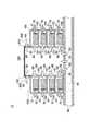
図4は、他の実施形態に係る機器収容室用空調システム11の外観を示す斜視図である。また、図5は、機器収容ラック21の通路43と直交する面における概略断面図およびフラップ300の拡大図である。図4および図5において図1から図3と同じ参照番号を付したものについては同じ構成であるので説明を省略する。図4に示すように、機器収容室用空調システム11の機器収容ラック21において、風圧調整部の他の形態であるフラップ301は、冷気導入部200の天面220に配される。このフラップ301は、図4および図5に示すように、開口部311、ヒンジ321および開閉部331を有する。開閉部331は、例えば樹脂またはゴム等で形成される板状の部材であり、ヒンジ321に接着またはビス留め等の方法で固定される。 FIG. 4 is a perspective view showing an appearance of an
上記フラップ301の開閉部331は、冷気導入部200内に流れ込む冷気60の風圧が機器収容ラック21の排気側の気圧よりも所定値以上高い場合に開いて、冷気導入部200内に流れ込む冷気60の一部を排気側に開放する(図5の破線部参照)。上記所定値は、通路43に流れ込む冷気60の流入圧および情報処理機器50に取り付けられた空冷ファン51の排気能力等を考慮して、開閉部331の厚さおよび材質の選択、または、ヒンジ321の回動抵抗の調整等により所望に設定することができる。これにより、機器収容室用空調システム11の機器収容ラック21は、ラック本体100の冷気導入口101から導入される冷気60による風圧の上昇を抑えて一定に保つことができるので、情報処理機器50に取り付けられた空冷ファン51に対して排気能力を上回る過大な負荷がかかることを防ぐことができる。 The opening / closing portion 331 of the
図6は、さらに他の実施形態に係る機器収容室用空調システム12の外観を示す斜視図である。図6において図1から図5と同じ参照番号を付したものについては同じ構成であるので説明を省略する。図6に示すように、機器収容室用空調システム12の機器収容ラック21において、風圧調整部のさらに他の形態であるフラップ302は、出入扉230に配される。このフラップ302は、図6に示すように、開口部312、把持部322および開閉部332を有する。開閉部332は、例えば樹脂またはゴム等で形成される板状の部材であり、ヒンジ321に接着またはビス留め等の方法で固定される。 FIG. 6 is a perspective view showing an appearance of an
上記フラップ302の開閉部332は、冷気導入部200内に流れ込む冷気60の風圧が機器収容ラック22の排気側の気圧よりも所定値以上高い場合に開いて、冷気導入部200内に流れ込む冷気60の一部を排気側に開放する。上記所定値は、通路43に流れ込む冷気60の流入圧および情報処理機器50に取り付けられた空冷ファン51の排気能力等を考慮して開閉部332の厚さおよび材質等を選択することで所望に設定することができる。これにより、機器収容室用空調システム12の機器収容ラック22は、ラック本体100の冷気導入口101から導入される冷気60による風圧の上昇を抑えて一定に保つことができるので、情報処理機器50に取り付けられた空冷ファン51に対して排気能力を上回る過大な負荷がかかることを防ぐことができる。 The open / close section 332 of the flap 302 opens when the wind pressure of the
図7は、さらに他の実施形態に係る機器収容室用空調システム13の一部を透視した斜視図である。また、図8は、機器収容ラック23の通路43と直交する面における概略断面図である。図7および図8において図1から図6と同じ参照番号を付したものについては同じ構成であるので説明を省略する。図7および図8に示すように、機器収容室用空調システム13の機器収容ラック23において、ラック本体100の各段のうちで情報処理機器50が収容されていない段には、冷気導入口101を塞いで冷気60の導入を遮断するブランクパネル400が取り付けられる。このとき、ラック本体100の下段から優先的に情報処理機器50が収容されるので、ブランクパネル400は、多くの場合、ラック本体100の上段から取り付けられる。 FIG. 7 is a perspective view of a part of the
上記ブランクパネル400は、それぞれその中央部に開口部410を有し、ラック本体100の内側の面に風圧調整部のさらに他の形態であるフラップ303が配される。このフラップ303は、図8に示すように、開口部313、把持部323および開閉部333を有する。開閉部333は、例えば樹脂またはゴム等で形成されたシート状または板状の部材であり、把持部320に接着またはビス留め等の方法で固定される。 Each of the
上記フラップ303の開閉部333は、冷気導入部200内に流れ込む冷気60の風圧が機器収容ラック23の排気側の気圧よりも所定値以上高い場合に開いて、冷気導入部200内に流れ込む冷気60の一部をラック本体100の熱気排出口102から排気側に開放する。上記所定値は、通路43に流れ込む冷気60の流入圧および情報処理機器50に取り付けられた空冷ファン51の排気能力等を考慮して開閉部332の厚さおよび材質等を選択することで所望に設定することができる。これにより、機器収容室用空調システム13の機器収容ラック23は、ラック本体100の大半の冷気導入口101がブランクパネル400で塞がれた場合でも、ラック本体100のブランクパネル400で塞がれていない冷気導入口101から導入される冷気60による風圧の上昇を抑えて一定に保つことができる。したがって、情報処理機器50に取り付けられた空冷ファン51に対して排気能力を上回る過大な負荷がかかることを防ぐことができる。 The opening / closing part 333 of the flap 303 opens when the wind pressure of the
図9は、さらに他の実施形態に係る機器収容室用空調システム14の外観を示す斜視図である。また、図10は、機器収容ラック24の通路43と直交する面における概略断面図である。図9および図10において図1から図8と同じ参照番号を付したものについては同じ構成であるので説明を省略する。図9に示すように、機器収容室用空調システム14の機器収容ラック24は、冷気導入部200の側面210に風圧調整部のさらに他の形態であるスリット500が形成されている。このスリット500は、図9および図10に示すように、冷気導入部200の側面210を水平に貫通している。 FIG. 9 is a perspective view showing an external appearance of an
上記スリット500は、冷気導入部200の内に流れ込む冷気60の一部を排気側に開放して冷気60の風圧の上昇を抑える。ここで、スリット500の幅および本数等は、通路43に流れ込む冷気60の流入圧および情報処理機器50に取り付けられた空冷ファン51の排気能力等を考慮して所望に設定することができる。これにより、機器収容室用空調システム14の機器収容ラック24は、上記フラップ300、301、302、303よりも簡易な風圧調整部であるスリット500によって、ラック本体100の冷気導入口101から導入される冷気60による風圧の上昇を抑えることができる。したがって、情報処理機器50に取り付けられた空冷ファン51に対して排気能力を上回る過大な負荷がかかることがなく、空冷ファン51の故障を防ぐことができる。なお、スリット500は、冷気導入部200の天面220または上記のブランクパネル400に形成されてもよく、冷気導入部200の側面210も含めてこれらの複数箇所に形成されてもよい。 The
図11は、さらに他の実施形態に係る機器収容室用空調システム15の外観を示す斜視図である。また、図12は、機器収容ラック25の通路43と直交する面における概略断面図である。図11および図12において図1から図10と同じ参照番号を付したものについては同じ構成であるので説明を省略する。図11に示すように、機器収容室用空調システム15の機器収容ラック25は、冷気導入部200の側面210に風圧調整部のさらに他の形態であるノズル600を備えている。このノズル600は、図11および図12に示すように、冷気導入部200の側面210に複数配されている。 FIG. 11 is a perspective view showing an appearance of an
上記ノズル600は、冷気導入部200の内に流れ込む冷気60の一部を排気側に開放して冷気60の風圧の上昇を抑える。ここで、ノズル600の数等は、通路43に流れ込む冷気60の流入圧および情報処理機器50に取り付けられた空冷ファン51の排気能力等を考慮して所望に設定することができる。これにより、機器収容室用空調システム15の機器収容ラック25は、上記フラップ300、301、302、303よりも簡易な風圧調整部であるノズル600によって、ラック本体100の冷気導入口101から導入される冷気60による風圧の上昇を抑えることができる。したがって、情報処理機器50に取り付けられた空冷ファン51に対して排気能力を上回る過大な負荷がかかることを防ぐことができる。なお、ノズル600は、冷気導入部200の天面220または上記のブランクパネル400に配されてもよく、冷気導入部200の側面210も含めてこれらの複数箇所に配されてもよい。 The
以上、本発明を実施の形態を用いて説明したが、本発明の技術的範囲は上記実施の形態に記載の範囲には限定されない。上記実施の形態に、多様な変更または改良を加えることができることが当業者に明らかである。その様な変更または改良を加えた形態も本発明の技術的範囲に含まれ得ることが、特許請求の範囲の記載から明らかである。 As mentioned above, although this invention was demonstrated using embodiment, the technical scope of this invention is not limited to the range as described in the said embodiment. It will be apparent to those skilled in the art that various modifications and improvements can be made to the above-described embodiment. It is apparent from the scope of the claims that the embodiments added with such changes or improvements can be included in the technical scope of the present invention.
10、11、12、13、14、15 機器収容室用空調システム、20、21、22、23、24、25 機器収容ラック、30 空調装置、31 吸気口、32 吹出口、40 二重床、41 内部空間、42 通風板、50 情報処理機器、51 空冷ファン、60 冷気、70 熱気、100 ラック本体、101 冷気導入口、102 熱気排出口、200 冷気導入部、210 側面、220 天面、230 出入扉、300、301、302、303 フラップ、310、311、312、313 開口部、320、322、323 把持部、321 ヒンジ、330、331、332、333 開閉部、400 ブランクパネル、410 開口部、500 スリット、600 ノズル 10, 11, 12, 13, 14, 15 Equipment storage room air conditioning system, 20, 21, 22, 23, 24, 25 Equipment storage rack, 30 Air conditioner, 31 Air inlet, 32 Air outlet, 40 Double floor, 41 Internal space, 42 Ventilation plate, 50 Information processing equipment, 51 Air cooling fan, 60 Cold air, 70 Hot air, 100 Rack body, 101 Cold air inlet, 102 Hot air outlet, 200 Cold air inlet, 210 Side, 220 Top, 230 Entrance door, 300, 301, 302, 303 Flap, 310, 311, 312, 313 Opening, 320, 322, 323 Grasping part, 321 Hinge, 330, 331, 332, 333 Opening / closing part, 400 Blank panel, 410
Claims (10)
Translated fromJapanese空調装置から出力された冷気を前記ラック本体に導入する冷気導入部と、
前記ラック本体において前記冷気導入部を有する側と前記情報処理機器を挟んで反対側に配され、前記冷気導入部と前記情報処理機器の前記排気ファンとともに空気の流れを作る熱気排出口と、
前記冷気導入部に配され、前記排気ファンにかかる風圧を一定に保つ空気の流れを前記冷気導入部内の風圧を排気側に開放することにより調整する風圧調整部と、
を備える機器収容ラック。A rack body for housing information processing equipment having an exhaust fan;
A cool air introduction section for introducing cool air output from the air conditioner into the rack body;
A hot air outlet that is arranged on the opposite side of the rack body with the cold air introduction portion and the information processing device, and that creates an air flow with the cold air introduction portion and the exhaust fan of the information processing device;
A wind pressure adjusting sectionfor adjusting by said disposed in the cold air inlet portion to openthe flow of air to keep the air pressure exerted on the exhaust fan to a constant air pressure in the cold air inlet part on the exhaust side,
Equipment storage rack comprising.
前記冷気は前記冷気導入部の下側から導入され、
前記風圧調整部は、前記冷気導入部の前記天面に設けられて、前記冷気導入部の下側から導入される前記冷気の風圧を前記排気側に開放する請求項1に記載の機器収容ラック。The cold air introduction part has a top surface and a side surface that separates a surface of the rack body where the cold air is introduced from the exhaust side,
The cold air is introduced from below the cold air introduction part,
2. The equipment storage rack according to claim 1, wherein the wind pressure adjusting unit is provided on the top surface of the cold air introducing unit and opens the wind pressure of the cold air introduced from the lower side of the cold air introducing unit to the exhaust side. .
前記冷気は前記冷気導入部の下側から導入され、
前記風圧調整部は、前記冷気導入部の前記側面の上部に設けられて、前記冷気導入部の下側から導入される前記冷気の風圧を排気側に開放する請求項1に記載の機器収容ラック。The cold air introduction part has a top surface and a side surface that separates a surface of the rack body where the cold air is introduced from the exhaust side,
The cold air is introduced from below the cold air introduction part,
2. The equipment storage rack according to claim 1, wherein the wind pressure adjusting unit is provided at an upper portion of the side surface of the cold air introducing unit, and opens the wind pressure of the cold air introduced from the lower side of the cold air introducing unit to the exhaust side. .
冷気を出力する空調装置と、
排気ファンを有する情報処理機器を収容する機器収容ラックと、
前記空調装置から出力された冷気を前記機器収容ラックに送風する送風路と
を備え、
前記機器収容ラックは、
前記情報処理機器を収容するラック本体と、
前記冷気を前記ラック本体に導入する冷気導入部と、
前記ラック本体において前記冷気導入部を有する側と前記情報処理機器を挟んで反対側に配され、前記冷気導入部と前記情報処理機器の前記排気ファンとともに空気の流れを作る熱気排出口と、
前記冷気導入部に配され、前記排気ファンにかかる風圧を一定に保つ空気の流れを前記冷気導入部内の風圧を排気側に開放することにより調整する風圧調整部と、
を備える機器収容室用空調システム。An air conditioning system for an equipment storage room that adjusts the temperature of an equipment storage room that houses information processing equipment,
An air conditioner that outputs cold air;
An equipment storage rack for storing information processing equipment having an exhaust fan;
An air passage that blows cool air output from the air conditioner to the equipment housing rack,
The equipment storage rack is
A rack body that houses the information processing device;
A cold air introduction section for introducing the cold air into the rack body;
A hot air outlet that is arranged on the opposite side of the rack body with the cold air introduction portion and the information processing device, and that creates an air flow with the cold air introduction portion and the exhaust fan of the information processing device;
A wind pressure adjusting sectionfor adjusting by said disposed in the cold air inlet portion to openthe flow of air to keep the air pressure exerted on the exhaust fan to a constant air pressure in the cold air inlet part on the exhaust side,
An air conditioning system for equipment storage rooms.
Priority Applications (1)
| Application Number | Priority Date | Filing Date | Title |
|---|---|---|---|
| JP2006146697AJP4873997B2 (en) | 2006-05-26 | 2006-05-26 | Equipment storage rack and equipment storage room air conditioning system |
Applications Claiming Priority (1)
| Application Number | Priority Date | Filing Date | Title |
|---|---|---|---|
| JP2006146697AJP4873997B2 (en) | 2006-05-26 | 2006-05-26 | Equipment storage rack and equipment storage room air conditioning system |
Publications (2)
| Publication Number | Publication Date |
|---|---|
| JP2007316989A JP2007316989A (en) | 2007-12-06 |
| JP4873997B2true JP4873997B2 (en) | 2012-02-08 |
Family
ID=38850784
Family Applications (1)
| Application Number | Title | Priority Date | Filing Date |
|---|---|---|---|
| JP2006146697AActiveJP4873997B2 (en) | 2006-05-26 | 2006-05-26 | Equipment storage rack and equipment storage room air conditioning system |
Country Status (1)
| Country | Link |
|---|---|
| JP (1) | JP4873997B2 (en) |
Families Citing this family (52)
| Publication number | Priority date | Publication date | Assignee | Title |
|---|---|---|---|---|
| US7430118B1 (en)* | 2007-06-04 | 2008-09-30 | Yahoo! Inc. | Cold row encapsulation for server farm cooling system |
| JP2009071084A (en)* | 2007-09-14 | 2009-04-02 | Hitachi Ltd | Control device with forced air cooling |
| ES2595802T3 (en)* | 2007-11-09 | 2017-01-03 | Knürr GmbH | System and method for air conditioning |
| JP5017088B2 (en)* | 2007-12-27 | 2012-09-05 | 三洋電機株式会社 | Electronic equipment cooling device |
| JP5308750B2 (en)* | 2008-03-26 | 2013-10-09 | 株式会社Nttファシリティーズ | Rack air conditioning system |
| JP5243092B2 (en)* | 2008-04-21 | 2013-07-24 | 株式会社Nttファシリティーズ | Rack type air conditioner |
| JP2009282753A (en)* | 2008-05-22 | 2009-12-03 | Nec Fielding Ltd | Rack, air conditioning system, and air conditioning method |
| US10058011B2 (en) | 2008-06-19 | 2018-08-21 | Panduit Corp. | Passive cooling systems for network cabinet |
| JP5346514B2 (en)* | 2008-07-22 | 2013-11-20 | 株式会社Nttファシリティーズ | Air conditioning system for computer room |
| JP2010038480A (en)* | 2008-08-07 | 2010-02-18 | Shimizu Corp | Air conditioning system |
| JP2010043817A (en)* | 2008-08-18 | 2010-02-25 | Fuji Denki Sosetsu Co Ltd | Air conditioning system of server chamber |
| JP5296457B2 (en)* | 2008-08-27 | 2013-09-25 | 高砂熱学工業株式会社 | Air conditioning system |
| US9072200B2 (en) | 2008-09-10 | 2015-06-30 | Schneider Electric It Corporation | Hot aisle containment panel system and method |
| JP5390147B2 (en)* | 2008-09-16 | 2014-01-15 | 高砂熱学工業株式会社 | Air conditioning system for high-density heat load room |
| JP4735690B2 (en) | 2008-09-16 | 2011-07-27 | 日立電線株式会社 | Data center |
| JP2009079890A (en)* | 2008-10-02 | 2009-04-16 | Softbank Idc Corp | Air-conditioning system |
| JP5264432B2 (en)* | 2008-11-17 | 2013-08-14 | 日東工業株式会社 | Inter-rack passage shielding structure |
| JP5600388B2 (en)* | 2008-12-01 | 2014-10-01 | 株式会社大林組 | Server room air conditioning system |
| JP2010164218A (en)* | 2009-01-14 | 2010-07-29 | Shinryo Corp | Air-conditioning method of server machine room |
| JP5258046B2 (en)* | 2009-01-21 | 2013-08-07 | 株式会社Nttファシリティーズ | Inter-rack passage shielding structure |
| JP5219213B2 (en)* | 2009-01-21 | 2013-06-26 | 株式会社Nttファシリティーズ | Inter-rack passage shielding structure |
| JP5258047B2 (en)* | 2009-01-21 | 2013-08-07 | 株式会社Nttファシリティーズ | Inter-rack passage shielding structure |
| JP2010168769A (en)* | 2009-01-21 | 2010-08-05 | Ntt Facilities Inc | Inter-rack passage shielding structure |
| US8184435B2 (en) | 2009-01-28 | 2012-05-22 | American Power Conversion Corporation | Hot aisle containment cooling system and method |
| JP5184399B2 (en)* | 2009-02-17 | 2013-04-17 | 株式会社Nttファシリティーズ | Air conditioning system for computer room |
| JP5219283B2 (en)* | 2009-03-26 | 2013-06-26 | 株式会社関電エネルギーソリューション | Air conditioning system and air conditioning control method |
| US8054625B2 (en) | 2009-04-21 | 2011-11-08 | Yahoo! Inc. | Cold row encapsulation for server farm cooling system |
| US10212858B2 (en) | 2009-04-21 | 2019-02-19 | Excalibur Ip, Llc | Cold row encapsulation for server farm cooling system |
| US8360833B2 (en) | 2009-05-28 | 2013-01-29 | American Power Conversion Corporation | Method and apparatus for attachment and removal of fans while in operation and without the need for tools |
| US8031468B2 (en) | 2009-06-03 | 2011-10-04 | American Power Conversion Corporation | Hot aisle containment cooling unit and method for cooling |
| JP5052564B2 (en)* | 2009-06-04 | 2012-10-17 | 日立電線ネットワークス株式会社 | Intake / exhaust structure of heat-generating equipment storage rack and data center |
| US7944692B2 (en) | 2009-06-12 | 2011-05-17 | American Power Conversion Corporation | Method and apparatus for installation and removal of overhead cooling equipment |
| US20110009047A1 (en)* | 2009-07-09 | 2011-01-13 | Yahoo! Inc. | Integrated Building Based Air Handler for Server Farm Cooling System |
| JP5597957B2 (en)* | 2009-09-04 | 2014-10-01 | 富士通株式会社 | Data center, cooling system, and cooling method for IT equipment |
| JP5268855B2 (en)* | 2009-10-09 | 2013-08-21 | ヤフー株式会社 | Rack and information processing equipment accommodation |
| JP5268072B2 (en)* | 2009-10-13 | 2013-08-21 | 株式会社Nttファシリティーズ | Air conditioning control system and operation method thereof |
| JP5283602B2 (en)* | 2009-10-16 | 2013-09-04 | 高砂熱学工業株式会社 | Air conditioning system for electronic communication equipment room |
| WO2011049033A1 (en)* | 2009-10-23 | 2011-04-28 | Okada Ryosuke | Data center and computer storing rack therefor |
| JP5405287B2 (en)* | 2009-12-21 | 2014-02-05 | 大成建設株式会社 | Rack air conditioner unit for heat generating equipment and rack air conditioner |
| JP2011159144A (en)* | 2010-02-02 | 2011-08-18 | Yahoo Japan Corp | Server room and method of cooling the same |
| JP5389699B2 (en)* | 2010-03-09 | 2014-01-15 | 大成建設株式会社 | Rack air conditioner for heating equipment |
| JP2012053747A (en)* | 2010-09-02 | 2012-03-15 | Ntt Facilities Inc | Containerized data center |
| JP5155370B2 (en)* | 2010-09-21 | 2013-03-06 | 東芝Itサービス株式会社 | Panel device and method of using panel device |
| JP4792122B2 (en)* | 2010-09-24 | 2011-10-12 | 日立電線株式会社 | Data center |
| CN102445967A (en)* | 2010-10-13 | 2012-05-09 | 鸿富锦精密工业(深圳)有限公司 | server chassis |
| JP4766195B2 (en)* | 2010-12-08 | 2011-09-07 | 日立電線株式会社 | Data center |
| CN103443550B (en) | 2011-01-11 | 2018-11-20 | 施耐德电气It公司 | cooling unit and method |
| JP5587384B2 (en)* | 2012-11-12 | 2014-09-10 | 株式会社日立システムズ | Hanging capping system |
| JP5587383B2 (en)* | 2012-11-12 | 2014-09-10 | 株式会社日立システムズ | Hanging capping system |
| JP6141666B2 (en)* | 2013-03-29 | 2017-06-07 | 株式会社Nttファシリティーズ | Computer room air conditioning system |
| JP6590713B2 (en)* | 2016-01-28 | 2019-10-16 | 株式会社Nttファシリティーズ | Computer room air conditioning system |
| JP2017215055A (en)* | 2016-05-30 | 2017-12-07 | 篠原電機株式会社 | Air conditioning device for server system |
Family Cites Families (11)
| Publication number | Priority date | Publication date | Assignee | Title |
|---|---|---|---|---|
| JPS58167833U (en)* | 1982-04-30 | 1983-11-09 | 株式会社竹中工務店 | Room differential pressure adjustment device |
| JPS60149191U (en)* | 1984-03-14 | 1985-10-03 | 日本電気株式会社 | Forced air cooling structure for electronic equipment |
| JPH0328642A (en)* | 1989-06-26 | 1991-02-06 | Daikin Plant Kk | Internal pressure regulator for sealing chamber |
| JP2934493B2 (en)* | 1990-10-24 | 1999-08-16 | 株式会社日立製作所 | Electronic equipment cooling device |
| JPH062779U (en)* | 1992-06-12 | 1994-01-14 | 株式会社東芝 | Ventilation structure for electronic devices |
| JP3784674B2 (en)* | 2001-07-31 | 2006-06-14 | 三菱電機株式会社 | Electronic equipment |
| JP2003142858A (en)* | 2001-11-05 | 2003-05-16 | Kawamura Electric Inc | Wall-surface panel for rack |
| JP3835615B2 (en)* | 2002-11-21 | 2006-10-18 | 株式会社Nttファシリティーズ | Air conditioning system for computer room |
| US6859366B2 (en)* | 2003-03-19 | 2005-02-22 | American Power Conversion | Data center cooling system |
| JP2005268546A (en)* | 2004-03-18 | 2005-09-29 | Nikon Corp | Enclosure unit storage rack |
| JP4633407B2 (en)* | 2004-08-27 | 2011-02-16 | 株式会社Nttファシリティーズ | Air conditioning system for computer room |
- 2006
- 2006-05-26JPJP2006146697Apatent/JP4873997B2/enactiveActive
Also Published As
| Publication number | Publication date |
|---|---|
| JP2007316989A (en) | 2007-12-06 |
Similar Documents
| Publication | Publication Date | Title |
|---|---|---|
| JP4873997B2 (en) | Equipment storage rack and equipment storage room air conditioning system | |
| JP3842631B2 (en) | Air conditioning systems for communication / information processing equipment rooms, etc. | |
| ES2374707T3 (en) | COLD HALL ISOLATION. | |
| JP2002156136A (en) | Air conditioning systems for communication equipment rooms, etc. | |
| CA2578458C (en) | Self contained heating/cooling roof top unit with built in independent pressure relief | |
| WO2013057844A1 (en) | Air conditioning system of communication/information processing apparatus chamber, etc. | |
| JP2016110273A (en) | Rack and electronic unit cooling method | |
| JP2005172309A (en) | Blower and air conditioning system for room | |
| JP6805714B2 (en) | Data center | |
| JP5182698B2 (en) | Rack cabinet and method for cooling electronic equipment mounted in rack cabinet | |
| JP5346514B2 (en) | Air conditioning system for computer room | |
| JP5492716B2 (en) | Air conditioning system for data center | |
| WO2011049033A1 (en) | Data center and computer storing rack therefor | |
| JP4037147B2 (en) | Outdoor unit placement system | |
| JP2009133617A (en) | Air conditioning system | |
| JP2014190624A (en) | Air conditioning system | |
| KR102540630B1 (en) | System for controlling temperature and air quality of indoor of building and control method thereof | |
| JP4936181B2 (en) | Smoke control system | |
| KR101129751B1 (en) | Ventilation system | |
| KR20170010304A (en) | By-pass apparatus for a ventilation system | |
| JP2014092802A (en) | Computer room air conditioning system | |
| JP3071785B1 (en) | Information processor rack | |
| JP2014031975A (en) | Air conditioning system for information processing apparatus room | |
| JP2023042942A (en) | Air conditioning system of data center | |
| JP6129618B2 (en) | Air conditioning system |
Legal Events
| Date | Code | Title | Description |
|---|---|---|---|
| A977 | Report on retrieval | Free format text:JAPANESE INTERMEDIATE CODE: A971007 Effective date:20080723 | |
| A131 | Notification of reasons for refusal | Free format text:JAPANESE INTERMEDIATE CODE: A131 Effective date:20080812 | |
| RD13 | Notification of appointment of power of sub attorney | Free format text:JAPANESE INTERMEDIATE CODE: A7433 Effective date:20081003 | |
| A521 | Request for written amendment filed | Free format text:JAPANESE INTERMEDIATE CODE: A523 Effective date:20081008 | |
| A521 | Request for written amendment filed | Free format text:JAPANESE INTERMEDIATE CODE: A523 Effective date:20081117 | |
| A131 | Notification of reasons for refusal | Free format text:JAPANESE INTERMEDIATE CODE: A131 Effective date:20090609 | |
| A711 | Notification of change in applicant | Free format text:JAPANESE INTERMEDIATE CODE: A712 Effective date:20090714 | |
| A521 | Request for written amendment filed | Free format text:JAPANESE INTERMEDIATE CODE: A523 Effective date:20090807 | |
| A02 | Decision of refusal | Free format text:JAPANESE INTERMEDIATE CODE: A02 Effective date:20100413 | |
| A521 | Request for written amendment filed | Free format text:JAPANESE INTERMEDIATE CODE: A523 Effective date:20100712 | |
| A911 | Transfer to examiner for re-examination before appeal (zenchi) | Free format text:JAPANESE INTERMEDIATE CODE: A911 Effective date:20100721 | |
| A912 | Re-examination (zenchi) completed and case transferred to appeal board | Free format text:JAPANESE INTERMEDIATE CODE: A912 Effective date:20100903 | |
| A01 | Written decision to grant a patent or to grant a registration (utility model) | Free format text:JAPANESE INTERMEDIATE CODE: A01 | |
| A61 | First payment of annual fees (during grant procedure) | Free format text:JAPANESE INTERMEDIATE CODE: A61 Effective date:20111122 | |
| FPAY | Renewal fee payment (event date is renewal date of database) | Free format text:PAYMENT UNTIL: 20141202 Year of fee payment:3 | |
| R150 | Certificate of patent or registration of utility model | Ref document number:4873997 Country of ref document:JP Free format text:JAPANESE INTERMEDIATE CODE: R150 Free format text:JAPANESE INTERMEDIATE CODE: R150 | |
| R250 | Receipt of annual fees | Free format text:JAPANESE INTERMEDIATE CODE: R250 | |
| R250 | Receipt of annual fees | Free format text:JAPANESE INTERMEDIATE CODE: R250 | |
| R250 | Receipt of annual fees | Free format text:JAPANESE INTERMEDIATE CODE: R250 | |
| S531 | Written request for registration of change of domicile | Free format text:JAPANESE INTERMEDIATE CODE: R313531 | |
| R350 | Written notification of registration of transfer | Free format text:JAPANESE INTERMEDIATE CODE: R350 | |
| R250 | Receipt of annual fees | Free format text:JAPANESE INTERMEDIATE CODE: R250 | |
| S111 | Request for change of ownership or part of ownership | Free format text:JAPANESE INTERMEDIATE CODE: R313113 | |
| R350 | Written notification of registration of transfer | Free format text:JAPANESE INTERMEDIATE CODE: R350 | |
| R250 | Receipt of annual fees | Free format text:JAPANESE INTERMEDIATE CODE: R250 | |
| S531 | Written request for registration of change of domicile | Free format text:JAPANESE INTERMEDIATE CODE: R313531 | |
| R350 | Written notification of registration of transfer | Free format text:JAPANESE INTERMEDIATE CODE: R350 | |
| R250 | Receipt of annual fees | Free format text:JAPANESE INTERMEDIATE CODE: R250 | |
| R250 | Receipt of annual fees | Free format text:JAPANESE INTERMEDIATE CODE: R250 | |
| R250 | Receipt of annual fees | Free format text:JAPANESE INTERMEDIATE CODE: R250 |