Movatterモバイル変換


[0]ホーム

URL:


JP4872922B2 - Reaction vessel - Google Patents

Reaction vessel
Download PDF

Info

Publication number
JP4872922B2
JP4872922B2JP2008000591AJP2008000591AJP4872922B2JP 4872922 B2JP4872922 B2JP 4872922B2JP 2008000591 AJP2008000591 AJP 2008000591AJP 2008000591 AJP2008000591 AJP 2008000591AJP 4872922 B2JP4872922 B2JP 4872922B2
Authority
JP
Japan
Prior art keywords
reaction
channel
plate
flow path
reaction chamber
Prior art date
Legal status (The legal status is an assumption and is not a legal conclusion. Google has not performed a legal analysis and makes no representation as to the accuracy of the status listed.)
Expired - Fee Related
Application number
JP2008000591A
Other languages
Japanese (ja)
Other versions
JP2009162619A (en
Inventor
信博 花房
尚弘 西本
正樹 叶井
Current Assignee (The listed assignees may be inaccurate. Google has not performed a legal analysis and makes no representation or warranty as to the accuracy of the list.)
Shimadzu Corp
Original Assignee
Shimadzu Corp
Priority date (The priority date is an assumption and is not a legal conclusion. Google has not performed a legal analysis and makes no representation as to the accuracy of the date listed.)
Filing date
Publication date
Application filed by Shimadzu CorpfiledCriticalShimadzu Corp
Priority to JP2008000591ApriorityCriticalpatent/JP4872922B2/en
Publication of JP2009162619ApublicationCriticalpatent/JP2009162619A/en
Application grantedgrantedCritical
Publication of JP4872922B2publicationCriticalpatent/JP4872922B2/en
Expired - Fee Relatedlegal-statusCriticalCurrent
Anticipated expirationlegal-statusCritical

Links

Images

Landscapes

Description

Translated fromJapanese

本発明は生物学的分析、生化学的分析、又は化学分析一般の分野において、医療や化学の現場において各種の解析や分析を行なうのに適する反応容器及びその反応容器を処理するための反応処理方法に関するものである。  The present invention relates to a reaction vessel suitable for performing various analyzes and analyzes in the field of medical analysis and chemistry in the fields of biological analysis, biochemical analysis, or chemical analysis in general, and reaction processing for processing the reaction vessel. It is about the method.

生化学的分析や通常の化学分析に使用する小型の反応装置としては、マイクロマルチチャンバ装置が使用されている。そのような装置としては、例えば平板状の基板表面に複数のウエルを形成したマイクロタイタープレートなどのマイクロウエル反応容器が用いられている(例えば特許文献1を参照。)。
また、微量の液体を定量的に扱うことができる微量液体秤取構造として、第1流路及び第2流路と、上記第1流路の流路壁に開口する第3流路と、第2流路の流路壁に開口して第3流路の一端と第2流路を連結し第3流路よりも相対的に毛管引力が働きにくい性質を第4流路とを有する構造を備えたものがある(例えば特許文献2,3を参照。)。その微量液体秤取構造によれば、第1流路に導入された液体が第3流路内に引き込まれた後、第1流路に残存する上記液体を取り除き、第3流路の容積に応じた体積の液体を第2流路に秤取することができる。
特開2005−177749号公報特開2004−163104号公報特開2005−114430号公報特許第3452717号公報
A micro multi-chamber apparatus is used as a small reaction apparatus used for biochemical analysis or normal chemical analysis. As such an apparatus, for example, a microwell reaction vessel such as a microtiter plate in which a plurality of wells are formed on a flat substrate surface is used (see, for example, Patent Document 1).
Moreover, as a trace liquid weighing structure capable of quantitatively handling a trace amount of liquid, a first channel and a second channel, a third channel opening in the channel wall of the first channel, A structure having a fourth channel having a property of opening the channel wall of the two channels and connecting one end of the third channel and the second channel so that capillary attraction is relatively difficult to work than the third channel. Some are provided (see, for example,Patent Documents 2 and 3). According to the trace liquid weighing structure, after the liquid introduced into the first flow path is drawn into the third flow path, the liquid remaining in the first flow path is removed, and the volume of the third flow path is increased. A corresponding volume of liquid can be weighed into the second flow path.
JP-A-2005-177749 JP 2004-163104 A JP 2005-114430 A Japanese Patent No. 3454717

従来のマイクロウエル反応容器は、使用時には反応容器の上面は大気に開放された状態となる。そのため、サンプルに外部から異物が進入する恐れがあるし、逆に反応生成物が外部の環境を汚染することもありうる。
また、特許文献2,3に開示された微量液体秤取構造では、第1流路の両端及び第2流路の両端に液体導入用のポートが形成されているが、それらのポートは大気に開放されており、それらのポートを介して反応生成物が外部の環境を汚染することもありうる。
そこで本発明は、反応容器の外部からの異物の進入や、外部への環境汚染を防ぐことができる反応容器及びその反応容器を用いた反応処理方法を提供することを目的とするものである。
When a conventional microwell reaction vessel is used, the upper surface of the reaction vessel is open to the atmosphere. Therefore, foreign matter may enter the sample from the outside, and conversely, the reaction product may contaminate the external environment.
Further, in the trace liquid weighing structure disclosed inPatent Documents 2 and 3, liquid introduction ports are formed at both ends of the first flow path and at both ends of the second flow path. It is possible that the reaction products are open and pollute the external environment through these ports.
Therefore, an object of the present invention is to provide a reaction vessel that can prevent entry of foreign matters from the outside of the reaction vessel and environmental contamination to the outside, and a reaction processing method using the reaction vessel.

本発明にかかる反応容器は、サンプルに反応を起こさせる複数の反応室を備えた反応プレートと、反応室の開口を閉じるように反応プレート上に被せられた弾性体プレートと、弾性体プレートを反応プレートに固定するために弾性体プレート上に配置された保持プレートとを備えている。  A reaction container according to the present invention reacts a reaction plate having a plurality of reaction chambers for causing a sample to react, an elastic plate placed on the reaction plate so as to close an opening of the reaction chamber, and an elastic plate. And a holding plate disposed on the elastic plate for fixing to the plate.

弾性体プレートは反応プレートとの対向面にサンプル及びその他の溶液を反応室に供給するための流路を備えている。その流路は全ての反応室に共通の主流路及び主流路から分岐して各反応室につながる個別流路とからなる。そして、各個別流路は一定容量をもつ計量流路及び計量流路と反応室との間に設けられた注入流路とからなっている。  The elastic plate is provided with a flow path for supplying a sample and other solutions to the reaction chamber on the surface facing the reaction plate. The flow path includes a main flow path common to all reaction chambers and individual flow paths that branch from the main flow path and connect to the reaction chambers. Each individual channel includes a metering channel having a constant capacity and an injection channel provided between the metering channel and the reaction chamber.

弾性体プレートと反応プレートの間は液密を保った密着状態を維持することが必要である。そのため、弾性体プレートとしては、シリコーン樹脂やPDMS(ポリジメチルシロキサン)などの弾性素材を使用する。そのような弾性素材を使用することにより弾性体プレートは自己吸着性によって反応プレートに液密を保って密着することができる。しかし、時間が経つと弾性体プレートと反応プレートとの境界に空気が入ることによって液密や気密を保つことができなくなる。そして、液漏れがわずかでも発生すると計量流路に液を送液することができなくなることがある。また、弾性体プレートと反応プレートとの境界の一部に空気漏れが生じると、加圧空気により複数の反応室に液を注入する際に全ての注入流路に圧力を均一にかけることができなくなり、反応室に液を注入することができなくなる。  It is necessary to maintain a close contact state between the elastic plate and the reaction plate while maintaining liquid tightness. Therefore, an elastic material such as silicone resin or PDMS (polydimethylsiloxane) is used as the elastic plate. By using such an elastic material, the elastic plate can be kept in close contact with the reaction plate by self-adsorption. However, as time passes, air enters the boundary between the elastic plate and the reaction plate, so that it becomes impossible to maintain liquid tightness or air tightness. If even a slight liquid leakage occurs, it may not be possible to send the liquid to the measuring channel. In addition, if air leaks at a part of the boundary between the elastic plate and the reaction plate, pressure can be applied uniformly to all the injection channels when the liquid is injected into a plurality of reaction chambers by pressurized air. The liquid cannot be injected into the reaction chamber.

そこで、本発明では、保持プレートは弾性体プレート側の面に抜け止め用の複数の突起を備えている。弾性体プレートにはその突起を通すための貫通穴が開けられ、反応プレートにはその突起が挿入される穴が開けられている。その突起と穴は保持プレートを反応プレートに対して位置決めするとともに、保持プレートにより弾性体プレートを反応プレートに対して液密を保って固定するように位置と寸法が設定されている。  Therefore, in the present invention, the holding plate is provided with a plurality of protrusions for preventing the retaining plate on the surface of the elastic body plate. The elastic plate is provided with a through hole through which the protrusion is passed, and the reaction plate is provided with a hole into which the protrusion is inserted. The protrusions and the holes are positioned and dimensioned so that the holding plate is positioned with respect to the reaction plate and the elastic plate is fixed with respect to the reaction plate by the holding plate while being liquid-tight.

このように、抜け止め用の突起で保持プレートを反応プレートに固定することにより弾性体プレートを反応プレートに対して固定し、弾性体プレートと反応プレートとの間の液密を保つ。
さらに保持プレートは、弾性体プレート側の面に弾性体プレートの流路形成部分又はその側方を集中的に押圧するための凸部を備えている。保持プレートの弾性体プレート側の面が抜け止め用の突起を除いて平坦面となっている場合には弾性体プレートを均一に押圧することになる。これに対し、保持プレートの弾性体プレート側の面に凸部が形成されていると、弾性体プレートの流路形成部分又はその側方を集中的に押圧することができ、流路側方の弾性体プレートと反応プレートとの密着性が向上し、凸部が形成されていない場合よりも流路の液密及び気密を高めることができる。また、保持プレートに凸部が設けられていることにより、流路の側方で弾性体プレートと反応プレートの間に気泡が入り込んだときにその部分を集中的に押圧できるので、気泡を流路内又は流路とは反対側の凸部で押圧されていない部分へ容易に押し出すことができる。
In this way, the elastic plate is fixed to the reaction plate by fixing the holding plate to the reaction plate with the protrusion for preventing the drop, and the liquid tightness between the elastic plate and the reaction plate is maintained.
Furthermore, the holding plate is provided with a convex portion for intensively pressing the flow path forming portion of the elastic plate or the side thereof on the surface of the elastic plate. When the surface of the holding plate on the side of the elastic plate is a flat surface except for the protrusion for preventing the retaining plate, the elastic plate is pressed uniformly. On the other hand, if the convex portion is formed on the elastic plate side surface of the holding plate, the flow path forming portion of the elastic plate or the side thereof can be intensively pressed, and the elasticity of the side of the flow path can be increased. The adhesion between the body plate and the reaction plate is improved, and the liquid tightness and the air tightness of the flow path can be improved as compared with the case where the convex portion is not formed. In addition, since the convex portion is provided on the holding plate, when the bubbles enter between the elastic plate and the reaction plate on the side of the flow path, that portion can be pressed intensively, so It can be easily pushed out to a portion that is not pressed by the convex portion on the side opposite to the inner or flow path.

上記の凸部は、弾性体プレートの流路よりも広い幅でその流路上で流路に沿って設けられていてもよいし、弾性体プレートの流路の側方に流路に沿って設けられていてもよい。  The convex portion may be provided along the flow path on the flow path with a width wider than that of the elastic plate, or provided along the flow path on the side of the flow path of the elastic plate. It may be done.

さらに凸部は、反応室の周囲部に相当する部分にも設けられていてもよい。そうすれば、弾性体プレートによる反応室の密閉能力が向上する。  Furthermore, the convex part may be provided also in the part corresponded to the surrounding part of a reaction chamber. If it does so, the sealing capability of the reaction chamber by an elastic body plate will improve.

好ましい形態では、注入流路は計量流路よりも細く、主流路及び計量流路に液体が導入されるときの液体導入圧力並びに主流路内の液体がパージされるときのパージ圧力では液体を通さず、それらよりも加圧状態で液体を通すことのできる流路抵抗をもつ大きさに設定されている。この場合、反応室への液体の注入は、注入流路の流路抵抗を利用して加圧により行なわれるので、パッシブバルブと呼ばれる。パッシブバルブでは弾性体プレートと反応プレートの間の液密を保った密着状態を維持することがより重要になる。  In a preferred form, the injection channel is narrower than the metering channel, and the liquid is introduced at the liquid introduction pressure when the liquid is introduced into the main channel and the metering channel and at the purge pressure when the liquid in the main channel is purged. Rather, they are set to a size having flow path resistance that allows liquid to pass through in a pressurized state. In this case, since the liquid is injected into the reaction chamber by pressurization using the flow path resistance of the injection flow path, it is called a passive valve. In the passive valve, it is more important to maintain a close contact state between the elastic plate and the reaction plate while maintaining liquid tightness.

注入流路の水滴に対する接触角を90度以上とし、注入流路と計量流路の境界の面積は1〜10000000μm2とすることができる。ここで、注入流路が複数の流路により構成されている場合には、上記の面積は注入流路を構成する複数の流路それぞれの計量流路との境界の面積を意味する。このような条件を満たしている場合には、主流路及び計量流路に液体が導入されるときに液体が注入流路に浸入しにくくなり、主流路及び計量流路に液体を導入するときの導入圧力を大きくすることができる。The contact angle of the injection channel with respect to the water droplets can be 90 degrees or more, and the area of the boundary between the injection channel and the metering channel can be 1 to 10000000 μm2 . Here, in the case where the injection channel is constituted by a plurality of channels, the above-mentioned area means the area of the boundary with each of the plurality of channels constituting the injection channel. When such a condition is satisfied, it is difficult for the liquid to enter the injection channel when the liquid is introduced into the main channel and the metering channel, and when the liquid is introduced into the main channel and the metering channel. The introduction pressure can be increased.

弾性体プレートは反応室に接続された反応室エアー抜き流路をさらに備えていることが好ましい。その場合には、注入流路から反応室に液を注入する際に、注入された液量に相当する空気を反応室から排出することができるので、反応室への液注入が容易になる。  The elastic plate preferably further includes a reaction chamber air vent channel connected to the reaction chamber. In that case, when liquid is injected into the reaction chamber from the injection flow path, air corresponding to the amount of the injected liquid can be discharged from the reaction chamber, so that liquid injection into the reaction chamber is facilitated.

主流路、個別流路及び反応室エアー抜き流路は全体として閉流路になっていることが好ましい。その場合は外部からサンプルに異物が侵入するのを阻止することができるとともに、この反応容器内での反応生成物が外部環境を汚染するのも阻止することができる。  The main flow path, the individual flow path, and the reaction chamber air vent flow path are preferably closed as a whole. In this case, foreign substances can be prevented from entering the sample from the outside, and reaction products in the reaction container can also be prevented from contaminating the external environment.

主流路は各個別流路への分岐部の下流に流路が狭くなった部分が形成されており、その流路が狭くなった部分の流路抵抗は計量流路の流路抵抗よりは大きく、注入流路の流路抵抗よりは小さくなるように設定されていることが好ましい。その場合は、主流路に液を供給すると、流路抵抗に従って上流側の計量流路から順に液が供給されていく。すなわち、最上流側の計量流路に送液され、その計量流路に液が充填されるまでは液は主流路を通って下流に流れることはない。その計量流路に液が充填されると、その計量流路との分岐位置の主流路の流路抵抗が注入流路の流路抵抗よりも小さいために、液は主流路を通って次の下流の計量流路へと供給されていく。このようにして最下流の計量流路まで順に液が充填されていく。その後、主流路に残った液を加圧空気でパージし、主流路全体に空気圧で加圧すれば、各計量流路に充填されていた液がそれぞれの反応室に同時に注入される。  The main channel is formed with a narrowed channel downstream of the branch to each individual channel, and the channel resistance of the narrow channel is greater than the channel resistance of the metering channel. In addition, it is preferably set to be smaller than the channel resistance of the injection channel. In that case, when the liquid is supplied to the main flow path, the liquid is sequentially supplied from the upstream measurement flow path in accordance with the flow path resistance. That is, the liquid does not flow downstream through the main flow path until the liquid is fed to the most upstream side flow path and filled with the liquid. When the metering flow path is filled with liquid, the flow resistance of the main flow path at the branching position with respect to the measurement flow path is smaller than the flow resistance of the injection flow path. It is supplied to the downstream metering channel. In this manner, the liquid is sequentially filled up to the most downstream metering channel. Thereafter, the liquid remaining in the main flow path is purged with pressurized air, and if the entire main flow path is pressurized with air pressure, the liquid filled in each metering flow path is simultaneously injected into each reaction chamber.

反応プレートは密閉可能に設けられたサンプル導入口を介して外部からサンプルを注入でき、主流路に接続されるサンプル導入部をさらに備えていることが好ましい。そして、そのサンプル導入口は尖端の鋭利な分注器具により貫通でき、かつ貫通後に分注器具を引き抜くとその貫通孔を弾性によって閉じることのできる弾性部材によって封止されていることが好ましい。これにより、弾性部材を介してサンプル導入部にサンプル液を注入することができ、その後サンプル液がサンプル導入部外に漏れるのを防止することができる。  It is preferable that the reaction plate further includes a sample introduction part that can inject a sample from the outside through a sample introduction port provided in a hermetically sealed manner and is connected to the main flow path. The sample introduction port is preferably sealed by an elastic member that can be penetrated by a sharp dispensing instrument having a sharp tip and that can close the through hole by elasticity when the dispensing instrument is pulled out after penetration. Thereby, a sample liquid can be inject | poured into a sample introduction part via an elastic member, and it can prevent that a sample liquid leaks out of a sample introduction part after that.

サンプル導入部は容器を形成していて、その容器には予めサンプル前処理液又は試薬を封入しておいてもよい。その場合には、サンプル導入部にサンプル前処理液又は試薬を分注する必要がなくなる。  The sample introduction part forms a container, and the sample pretreatment liquid or reagent may be sealed in the container in advance. In that case, there is no need to dispense the sample pretreatment liquid or reagent into the sample introduction part.

反応プレートは試薬容器をさらに備えていてもよく、その試薬容器にはサンプル液の反応に使用される試薬を予め収容しフィルムで封止されているか、又は開閉可能なキャップを備えて試薬を注入できるようにすることができる。その場合には、試薬を収容するための容器を別途準備する必要がなくなる。  The reaction plate may further include a reagent container, which contains a reagent used for the reaction of the sample solution in advance and is sealed with a film, or has a cap that can be opened and closed to inject the reagent. Can be able to. In that case, it is not necessary to separately prepare a container for containing the reagent.

反応プレートは遺伝子増幅反応を行なうための遺伝子増幅容器も備えておくことができる。その場合は測定対象の遺伝子を微量にしか含んでいないサンプル液でもPCR法やLAMP法など遺伝子増幅反応によって反応容器上で遺伝子を増幅して分析精度を高めることができるようになる。そして、遺伝子増幅容器を備えている場合でも遺伝子増幅反応を閉じた空間内で行い、分析終了後はその空間を閉じたまま廃棄処理をすることができるようにすれば、外部からの汚染を阻止できるとともに、他のサンプルを汚染することも阻止することができる。  The reaction plate can also be equipped with a gene amplification container for performing a gene amplification reaction. In that case, even in a sample solution containing only a very small amount of the gene to be measured, the analysis accuracy can be increased by amplifying the gene on the reaction vessel by a gene amplification reaction such as PCR method or LAMP method. And even if a gene amplification container is provided, if the gene amplification reaction is performed in a closed space and the analysis can be performed with the space closed after the analysis is completed, contamination from outside can be prevented. While being able to prevent contamination of other samples.

この反応容器はシリンダ、及びシリンダ内に配置されたプランジャを含むシリンジをさらに備えていてもよい。そのシリンジを主流路及び他の流路に切り替えて接続するための切替えバルブをさらに備えていることが好ましい。その切替えバルブの一例はロータリー式バルブである。  The reaction vessel may further include a cylinder and a syringe including a plunger disposed in the cylinder. It is preferable to further include a switching valve for switching and connecting the syringe to the main channel and other channels. An example of the switching valve is a rotary valve.

反応室はその底部から光学的に測定が可能なように光透過性の材質にて構成されていることが好ましい。その場合には、反応室内の液体を他の容器へ移動させることなく光学的に測定することができる。  The reaction chamber is preferably made of a light transmissive material so that optical measurement can be performed from the bottom. In that case, the liquid in the reaction chamber can be measured optically without being moved to another container.

また、反応室は反応室流路に導入される液体に検出しようとする遺伝子が含まれている場合にその遺伝子と反応するプローブを備えているようにすれば、反応室内でプローブに対応する塩基配列をもつ遺伝子の検出を行なうことができる。  In addition, if the reaction chamber contains a gene to be detected in the liquid introduced into the reaction chamber flow path, a base corresponding to the probe in the reaction chamber is provided. Detection of a gene having a sequence can be performed.

本発明にかかる反応容器では、抜け止め用の突起で保持プレートを反応プレートに固定することにより弾性体プレートを反応プレートに対して固定したので、時間が経っても弾性体プレートと反応プレートとの間の液密を維持することができるようになる。その結果、液漏れによって計量流路に液を送液することができなくなるという不都合は生じない。また、複数の反応室に液を注入する際に全ての注入流路に均一に圧力をかけることができるようになって、全ての反応室に同時に液を注入できるようになり、結果として分析精度が向上する。
さらに、保持プレートの弾性体プレート側の面に、弾性体プレートの流路形成部分を集中的に押圧して流路の液密及び気密を高めるための凸部を備えているので、流路形成部分における弾性体プレートと反応プレートとの間の耐圧がさらに向上する。
In the reaction container according to the present invention, the elastic plate is fixed to the reaction plate by fixing the holding plate to the reaction plate with the protrusion for preventing the separation, so that the elastic plate and the reaction plate are not separated from each other over time. It becomes possible to maintain liquid tightness between them. As a result, there is no inconvenience that the liquid cannot be sent to the measuring channel due to liquid leakage. In addition, when injecting liquids into multiple reaction chambers, it is possible to apply pressure uniformly to all the injection channels, and it is possible to inject liquids into all reaction chambers at the same time, resulting in analysis accuracy. Will improve.
Furthermore, the surface of the holding plate on the elastic body plate side is provided with a convex portion for intensively pressing the flow path forming portion of the elastic body plate to enhance the liquid and air tightness of the flow path. The pressure resistance between the elastic plate and the reaction plate in the portion is further improved.

また、抜け止め用の突起で保持プレートを反応プレートに固定する作業は単に嵌めこむだけですむので、位置合わせなどの調整も不要で、この反応容器の組立作業の作業性がよくなる。  In addition, since the work for fixing the holding plate to the reaction plate with the protrusion for preventing the removal is simply fitted, adjustment such as alignment is not required, and the workability of the reaction container assembly work is improved.

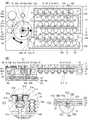
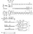
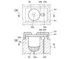
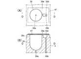
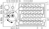
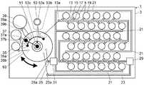
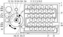
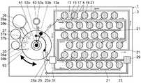
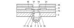
図1は反応容器の一実施例を示す図であり(A)は概略的な平面図、(B)は(A)のA−A位置での断面に計量流路15、注入流路17、反応室エアー抜き流路19,21、液体ドレイン空間29、エアードレイン空間31及びベローズ53の断面を加えた概略的な断面図、(C)はシリンジ51及びベローズ53近傍を拡大して示す概略的な断面図、(D)は保持プレートを反応プレートに固定する抜け止め用の突起近傍の断面図で、(A)におけるX−X線位置での断面図である。図2はこの実施例を分解して示す断面図及び切替えバルブの概略的な分解斜視図である。図3はこの実施例の1つの反応室近傍を示す概略図であり、(A)は平面図、(B)は斜視図、(C)は断面図である。図4はサンプル容器を拡大して示した図であり(A)は平面図、(B)は(A)のB−B位置での断面図である。図5は試薬容器を拡大して示した図であり(A)は平面図、(B)は(A)のC−C位置での断面図である。図6はエアー吸引用容器を拡大して示した図であり(A)は平面図、(B)は(A)のD−D位置での断面図である。  1A and 1B are diagrams showing an embodiment of a reaction vessel. FIG. 1A is a schematic plan view, and FIG. 1B is a sectional view taken along the line A-A in FIG. Schematic sectional view of the reaction chamberair vent channels 19, 21,liquid drain space 29,air drain space 31, and bellows 53, and a schematic cross-sectional view showing the vicinity of thesyringe 51 and bellows 53. (D) is a cross-sectional view in the vicinity of a retaining projection for fixing the holding plate to the reaction plate, and is a cross-sectional view at the position of line XX in (A). FIG. 2 is an exploded sectional view showing this embodiment and a schematic exploded perspective view of the switching valve. FIG. 3 is a schematic view showing the vicinity of one reaction chamber of this embodiment, (A) is a plan view, (B) is a perspective view, and (C) is a cross-sectional view. 4A and 4B are enlarged views of the sample container. FIG. 4A is a plan view, and FIG. 4B is a cross-sectional view taken along the line BB in FIG. 5A and 5B are enlarged views of the reagent container. FIG. 5A is a plan view, and FIG. 5B is a cross-sectional view taken along the line CC in FIG. 6A and 6B are enlarged views of the air suction container. FIG. 6A is a plan view, and FIG. 6B is a cross-sectional view taken along the DD line in FIG.

図1から図6を参照して反応容器の一実施例について説明する。
反応容器1は反応プレート3の一表面に開口部をもつ複数の反応室5を備えている。この実施例では6×6個の反応室5が千鳥状に配列されている。反応室5内に試薬7及びワックス9が収容されている。
An embodiment of the reaction vessel will be described with reference to FIGS.
Thereaction vessel 1 includes a plurality ofreaction chambers 5 having openings on one surface of thereaction plate 3. In this embodiment, 6 × 6reaction chambers 5 are arranged in a staggered manner. Areagent 7 andwax 9 are accommodated in thereaction chamber 5.

反応室5を含む反応プレート3の材質は特に限定されるものではないが、反応容器1を使い捨て可能として用いる場合には、安価に入手可能な素材があることが好ましい。そのような素材として、例えばポリプロピレン、ポリカーボネートなどの樹脂素材が好ましい。反応室5内の物質の検出を吸光度、蛍光、化学発光又は生物発光などにより行なう場合には、底面側から光学的な検出ができるようにするために光透過性の樹脂で形成されていることが好ましい。特に蛍光検出を行なう場合には、反応プレート3の材質として低自蛍光性(それ自身からの蛍光発生が少ない性質のこと)で光透過性の樹脂、例えばポリカーボネートなどの素材で形成されていることが好ましい。反応プレート3の厚さは0.2〜4.0mm(ミリメートル)、好ましくは1.0〜2.0mmである。蛍光検出用の低自蛍光性の観点からは反応プレート3の厚さは薄い方が好ましい。  The material of thereaction plate 3 including thereaction chamber 5 is not particularly limited. However, when thereaction vessel 1 is used as disposable, it is preferable that there is a material available at low cost. As such a material, for example, a resin material such as polypropylene and polycarbonate is preferable. When the substance in thereaction chamber 5 is detected by absorbance, fluorescence, chemiluminescence, bioluminescence, or the like, it should be formed of a light transmissive resin so that optical detection can be performed from the bottom side. Is preferred. Particularly when fluorescence detection is performed, thereaction plate 3 is made of a material such as a resin having a low autofluorescence property (a property of generating less fluorescence from itself) and a light transmitting resin such as polycarbonate. Is preferred. The thickness of thereaction plate 3 is 0.2 to 4.0 mm (millimeters), preferably 1.0 to 2.0 mm. From the viewpoint of low autofluorescence for fluorescence detection, thereaction plate 3 is preferably thin.

図1及び図3を参照して説明すると、反応プレート3上に反応室5の配列領域を覆って弾性体プレート11が配置されている。弾性体プレート11は例えばPDMS(ポリジメチルシロキサン)やシリコーンゴムからなる。弾性体プレート11の厚みは例えば1.0〜5.0mmである。弾性体プレート11は反応プレート3との接合面に溝を備えている。その溝と反応プレート3の表面によって、主流路13、計量流路15、注入流路17、反応室エアー抜き流路19,21、ドレイン空間エアー抜き流路23,25が形成されている。主流路13、計量流路15及び注入流路17は反応室流路を構成する。弾性体プレート11の反応プレート3との接合面には、反応室5上に配置された凹部27も形成されている。図1(A)及び図3(A),(B)では弾性体プレート11について溝及び凹部のみを図示している。  Referring to FIGS. 1 and 3, theelastic plate 11 is arranged on thereaction plate 3 so as to cover the arrangement region of thereaction chambers 5. Theelastic plate 11 is made of, for example, PDMS (polydimethylsiloxane) or silicone rubber. The thickness of theelastic plate 11 is, for example, 1.0 to 5.0 mm. Theelastic plate 11 is provided with a groove on the joint surface with thereaction plate 3. The groove and the surface of thereaction plate 3 form amain channel 13, ametering channel 15, aninjection channel 17, reaction chamberair vent channels 19 and 21, and drain spaceair vent channels 23 and 25. Themain flow path 13, themetering flow path 15 and theinjection flow path 17 constitute a reaction chamber flow path. Aconcave portion 27 disposed on thereaction chamber 5 is also formed on the joint surface of theelastic plate 11 with thereaction plate 3. In FIG. 1 (A) and FIGS. 3 (A) and 3 (B), only the grooves and recesses of theelastic plate 11 are shown.

主流路13は1本の流路からなり、すべての反応室5の近傍を通るように折れ曲がって形成されている。主流路13の一端は反応プレート3に設けられた貫通孔からなる流路13aに接続されている。流路13aは後述する切替えバルブ63のポートに接続されている。主流路13の他端は反応プレート3に形成された液体ドレイン空間29に接続されている。主流路13を構成する溝の寸法は例えば深さが400μm(マイクロメートル)、幅が500μmである。また、主流路13は、計量流路15が接続されている位置の下流側の所定長さ部分、例えば250μmの部分は幅が他の部分に比べて細く形成されており、例えばその幅は250μmである。  Themain flow path 13 is composed of a single flow path and is formed to be bent so as to pass through the vicinity of all thereaction chambers 5. One end of themain flow path 13 is connected to aflow path 13 a formed of a through hole provided in thereaction plate 3. Theflow path 13a is connected to a port of a switchingvalve 63 described later. The other end of themain channel 13 is connected to aliquid drain space 29 formed in thereaction plate 3. The dimensions of the grooves constituting themain flow path 13 are, for example, a depth of 400 μm (micrometer) and a width of 500 μm. In addition, themain flow path 13 has a predetermined length downstream of the position where themeasurement flow path 15 is connected, for example, a 250 μm portion is formed to be narrower than other portions, for example, the width is 250 μm. It is.

計量流路15は主流路13から分岐して反応室5ごとに設けられている。計量流路15の主流路13とは反対側の端部は反応室5の近傍に配置されている。計量流路15を構成する溝の深さは例えば400μmである。計量流路15は内部容量が所定容量、例えば2.5μL(マイクロリットル)に形成されている。計量流路15の主流路13に接続されている部分の幅寸法は、上述の主流路13の細くなっている部分よりも太く、例えば500μmに形成されている。これにより、主流路13の一端から流れてくる液体に対して、計量流路15が分岐している部分では主流路13の方が計量流路15よりも流路抵抗が大きくなっている。主流路13の一端から流れてくる液体は、まず計量流路15に流れ込み、計量流路15が液体で充填された後、主流路13の細くなっている部分を介して下流側へ流れるようになっている。  Themetering channel 15 is branched from themain channel 13 and provided for eachreaction chamber 5. The end of themetering channel 15 opposite to themain channel 13 is disposed in the vicinity of thereaction chamber 5. The depth of the groove constituting the measuringchannel 15 is 400 μm, for example. The measuringchannel 15 has an internal capacity of a predetermined capacity, for example, 2.5 μL (microliter). The width dimension of the part connected to themain flow path 13 of themeasurement flow path 15 is larger than the narrow part of themain flow path 13 described above, for example, 500 μm. Thereby, the flow resistance of themain flow path 13 is larger than that of themeasurement flow path 15 in the portion where themeasurement flow path 15 is branched with respect to the liquid flowing from one end of themain flow path 13. The liquid flowing from one end of themain channel 13 first flows into themetering channel 15, and after themetering channel 15 is filled with the liquid, it flows downstream through the narrowed portion of themain channel 13. It has become.

注入流路17も反応室5ごとに設けられている。注入流路17の一端は計量流路15に接続されている。注入流路17の他端は反応室5上に配置された凹部27に接続されて反応室5上に導かれている。注入流路17は、反応室5内と注入流路17内で圧力差がない状態で反応室5内の液密を保つ寸法で形成されている。この実施例では、注入流路17は複数の溝により構成されており、その溝の寸法は例えば深さが10μm、幅が20μm、ピッチが20μmであり、500μmの幅領域に13本の溝が形成されている。ここでは、注入流路17を構成する溝と計量流路15の境界の面積、すなわち注入流路17を構成する溝の断面積は200μm2である。また、凹部27は深さが例えば400μmであり、平面形状は反応室5よりも小さい円形である。Aninjection channel 17 is also provided for eachreaction chamber 5. One end of theinjection channel 17 is connected to themetering channel 15. The other end of theinjection channel 17 is connected to aconcave portion 27 disposed on thereaction chamber 5 and led to thereaction chamber 5. Theinjection channel 17 is formed with a dimension that maintains liquid tightness in thereaction chamber 5 in a state where there is no pressure difference between thereaction chamber 5 and theinjection channel 17. In this embodiment, theinjection channel 17 is composed of a plurality of grooves, and the dimensions of the grooves are, for example, a depth of 10 μm, a width of 20 μm, a pitch of 20 μm, and 13 grooves in a width region of 500 μm. Is formed. Here, the area of the boundary between the groove constituting theinjection channel 17 and themetering channel 15, that is, the cross-sectional area of the groove constituting theinjection channel 17 is 200 μm2 . Therecess 27 has a depth of, for example, 400 μm, and the planar shape is a circle smaller than thereaction chamber 5.

反応室エアー抜き流路19は反応室5ごとに設けられている。反応室エアー抜き流路19の一端は反応室5上に配置された凹部27に注入流路17とは異なる位置で接続されて反応室5上に配置されている。反応室エアー抜き流路19は、反応室5内と反応室エアー抜き流路19内で圧力差がない状態で反応室5内の液密を保つ寸法で形成されている。反応室エアー抜き流路19の他端は反応室エアー抜き流路21に接続されている。この実施例では、反応室エアー抜き流路19は複数の溝により構成されており、その溝の寸法は例えば深さが10μm、幅が20μm、ピッチが20μmであり、500μmの幅領域に13本の溝が形成されている。  A reaction chamberair vent channel 19 is provided for eachreaction chamber 5. One end of the reaction chamberair vent channel 19 is connected to arecess 27 disposed on thereaction chamber 5 at a position different from theinjection channel 17 and disposed on thereaction chamber 5. The reaction chamberair vent channel 19 is formed with a dimension that maintains liquid tightness in thereaction chamber 5 in a state where there is no pressure difference between thereaction chamber 5 and the reaction chamberair vent channel 19. The other end of the reaction chamberair vent channel 19 is connected to the reaction chamberair vent channel 21. In this embodiment, the reaction chamberair vent channel 19 is composed of a plurality of grooves, and the dimensions of the grooves are, for example, a depth of 10 μm, a width of 20 μm, a pitch of 20 μm, and 13 in a 500 μm width region. Grooves are formed.

反応室エアー抜き流路21はこの実施例では複数本設けられている。それぞれの反応室エアー抜き流路21には複数の反応室エアー抜き流路19が接続されている。反応室エアー抜き流路21は反応室エアー抜き流路19を反応プレート3に形成されたエアードレイン空間31に接続するためのものである。反応室エアー抜き流路21を構成する溝の寸法は例えば深さが400μm、幅が500μmである。  In this embodiment, a plurality of reaction chamberair vent channels 21 are provided. A plurality of reaction chamberair vent channels 19 are connected to each reaction chamberair vent channel 21. The reaction chamberair vent channel 21 is for connecting the reaction chamberair vent channel 19 to anair drain space 31 formed in thereaction plate 3. The dimensions of the grooves constituting the reaction chamberair vent channel 21 are, for example, a depth of 400 μm and a width of 500 μm.

ドレイン空間エアー抜き流路23は液体ドレイン空間29を後述する切替えバルブ63のポートに接続するためのものである。ドレイン空間エアー抜き流路23の一端は液体ドレイン空間29上に配置されている。ドレイン空間エアー抜き流路23の他端は反応プレート3に設けられた貫通孔からなる流路23aに接続されている。流路23aは後述する切替えバルブ63のポートに接続されている。ドレイン空間エアー抜き流路23を構成する溝の寸法は例えば深さが400μm、幅が500μmである。  The drain spaceair vent channel 23 is for connecting theliquid drain space 29 to a port of a switchingvalve 63 described later. One end of the drain spaceair vent channel 23 is disposed on theliquid drain space 29. The other end of the drain spaceair vent channel 23 is connected to achannel 23 a formed of a through hole provided in thereaction plate 3. Theflow path 23a is connected to a port of a switchingvalve 63 described later. The dimensions of the grooves constituting the drain spaceair vent channel 23 are, for example, a depth of 400 μm and a width of 500 μm.

ドレイン空間エアー抜き流路25はエアードレイン空間31を後述する切替えバルブ63のポートに接続するためのものである。ドレイン空間エアー抜き流路25の一端はエアードレイン空間31上に配置されている。ドレイン空間エアー抜き流路25の他端は反応プレート3に設けられた貫通孔からなる流路25aに接続されている。流路25aは後述する切替えバルブ63のポートに接続されている。ドレイン空間エアー抜き流路25を構成する溝の寸法は例えば深さが400μm、幅が500μmである。  The drain spaceair vent channel 25 is for connecting theair drain space 31 to a port of a switchingvalve 63 described later. One end of the drain spaceair vent channel 25 is disposed on theair drain space 31. The other end of the drain spaceair vent channel 25 is connected to achannel 25 a formed of a through hole provided in thereaction plate 3. Theflow path 25a is connected to a port of a switchingvalve 63 described later. The dimensions of the grooves constituting the drain spaceair vent channel 25 are, for example, a depth of 400 μm and a width of 500 μm.

弾性体プレート11上に保持プレート33(図1(A)での図示は省略している。)が配置されている。保持プレート33は弾性体プレート11を反応プレート3に固定するためのものである。保持プレート33には反応室5上の位置に貫通孔が形成されている。  A holding plate 33 (not shown in FIG. 1A) is disposed on theelastic body plate 11. The holdingplate 33 is for fixing theelastic body plate 11 to thereaction plate 3. A through hole is formed in the holdingplate 33 at a position on thereaction chamber 5.

図1及び図4を参照して説明すると、反応室5の配列領域及びドレイン空間29,31とは異なる位置で反応プレート3にサンプル容器35、試薬容器37及びエアー吸引用容器39が形成されている。  Referring to FIGS. 1 and 4, asample container 35, areagent container 37, and anair suction container 39 are formed on thereaction plate 3 at positions different from the arrangement region of thereaction chamber 5 and thedrain spaces 29, 31. Yes.

サンプル容器35近傍の反応プレート3に、サンプル容器35の底部から裏面に貫通しているサンプル流路35aと表面から裏面に貫通しているサンプル容器エアー抜き流路35bが形成されている。サンプル容器35の開口部周囲の反応プレート3上に突起部35cが配置されている。サンプル容器エアー抜き流路35b上の突起部35cに貫通孔からなるサンプル容器エアー抜き流路35dが形成されている。突起部35cの表面にサンプル容器35とサンプル容器エアー抜き流路35dを連通しているサンプル容器エアー抜き流路35eが形成されている。  In thereaction plate 3 in the vicinity of thesample container 35, asample channel 35a that penetrates from the bottom of thesample container 35 to the back surface and a sample containerair vent channel 35b that penetrates from the front surface to the back surface are formed. Aprotrusion 35 c is arranged on thereaction plate 3 around the opening of thesample container 35. A sample containerair vent channel 35d made of a through hole is formed in theprotrusion 35c on the sample containerair vent channel 35b. A sample containerair vent channel 35e that connects thesample container 35 and the sample containerair vent channel 35d is formed on the surface of theprotrusion 35c.

サンプル容器エアー抜き流路35eは例えば幅5〜200μm、深さ5〜200μmの寸法の1本又は複数本の細孔によって形成されており、サンプル容器35内とサンプル容器エアー抜き流路35d内で圧力差がない状態でサンプル容器35の液密を保つためのものである。突起部35c上にサンプル容器35及びエアー抜き流路35dを覆って弾性部材であるセプタム41が形成されている。セプタム41は例えばシリコーンゴムやPDMSなどの弾性材料によって形成されており、尖端が鋭利な分注器具により貫通でき、かつ貫通後に分注器具を引き抜くとその貫通孔を弾性によって閉じることができる。セプタム41上にセプタム41を固定するためのセプタムストッパ43が配置されている。セプタムストッパ43はサンプル容器35上に開口部をもつ。この実施例ではサンプル容器35内に予め試薬45が収容されている。  The sample containerair vent channel 35e is formed by, for example, one or a plurality of pores having a width of 5 to 200 μm and a depth of 5 to 200 μm. In thesample container 35 and the sample containerair vent channel 35d, This is for maintaining the liquid tightness of thesample container 35 in a state where there is no pressure difference. Aseptum 41, which is an elastic member, is formed on theprojection 35c so as to cover thesample container 35 and theair vent channel 35d. Theseptum 41 is made of, for example, an elastic material such as silicone rubber or PDMS. Theseptum 41 can be penetrated by a dispensing device having a sharp tip, and the through-hole can be closed by elasticity when the dispensing device is pulled out after penetration. Aseptum stopper 43 for fixing theseptum 41 is disposed on theseptum 41. Theseptum stopper 43 has an opening on thesample container 35. In this embodiment, thereagent 45 is accommodated in thesample container 35 in advance.

図5に示すように、試薬容器37近傍の反応プレート3に、試薬容器37の底部から裏面に貫通している試薬流路37aと表面から裏面に貫通している試薬容器エアー抜き流路37bが形成されている。試薬容器37の開口部周囲の反応プレート3上に突起部37cが配置されている。試薬容器エアー抜き流路37b上の突起部37cに貫通孔からなる試薬容器エアー抜き流路37dが形成されている。突起部37cの表面に試薬容器37と試薬容器エアー抜き流路37dを連通している試薬容器エアー抜き流路37eが形成されている。  As shown in FIG. 5, thereaction plate 3 in the vicinity of thereagent container 37 has areagent channel 37 a penetrating from the bottom to the back surface of thereagent container 37 and a reagent containerair vent channel 37 b penetrating from the surface to the back surface. Is formed. Aprotrusion 37 c is arranged on thereaction plate 3 around the opening of thereagent container 37. A reagent containerair vent channel 37d made of a through hole is formed in theprotrusion 37c on the reagent containerair vent channel 37b. A reagent containerair vent channel 37e that connects thereagent container 37 and the reagent containerair vent channel 37d is formed on the surface of theprotrusion 37c.

試薬容器エアー抜き流路37eは例えば幅5〜200μm、深さ5〜200μmの寸法の1本又は複数本の細孔によって形成されており、試薬容器37内と試薬容器エアー抜き流路37d内で圧力差がない状態で試薬容器37の液密を保つためのものである。突起部37c上に試薬容器37及びエアー抜き流路37dを覆って例えばアルミニウムからなるフィルム47が形成されている。試薬容器37内に希釈水49が収容されている。  The reagent containerair vent channel 37e is formed by, for example, one or a plurality of pores having a width of 5 to 200 μm and a depth of 5 to 200 μm. In thereagent container 37 and the reagent containerair vent channel 37d, This is for maintaining the liquid tightness of thereagent container 37 in a state where there is no pressure difference. Afilm 47 made of, for example, aluminum is formed on theprotrusion 37c so as to cover thereagent container 37 and theair vent channel 37d.Dilution water 49 is accommodated in thereagent container 37.

図6に示すように、エアー吸引用容器39は試薬容器37と同様の構成をもつ。すなわち、エアー吸引用容器39近傍の反応プレート3に、エアー吸引用容器39の底部から裏面に貫通しているエアー吸引用流路39aと表面から裏面に貫通しているエアー吸引用容器エアー抜き流路39bが形成されている。エアー吸引用容器39の開口部周囲の反応プレート3上にエアー吸引用容器エアー抜き流路39d,39eを備えた突起部39cが配置されている。突起部39c上に例えばアルミニウムからなるフィルム47が形成されている。エアー吸引用容器39内には液体及び固体は収容されておらず、エアーが充満している。  As shown in FIG. 6, theair suction container 39 has the same configuration as thereagent container 37. That is, theair suction channel 39a penetrating from the bottom of theair suction container 39 to the back surface and the air suction container air venting flow penetrating from the front surface to the back surface of thereaction plate 3 near theair suction container 39. Apath 39b is formed. On thereaction plate 3 around the opening of theair suction container 39, aprotrusion 39c provided with air suction containersair vent channels 39d and 39e is disposed. Afilm 47 made of, for example, aluminum is formed on theprotrusion 39c. Theair suction container 39 contains no liquid or solid but is filled with air.

弾性体プレート11を保持プレート33によって反応プレートに固定する構造を図1(D)を参照して説明する。
保持プレート33は反応プレート3側の面に抜け止め用の複数の突起100を備えている。突起100は図1(A)に示されているように、各反応室の注入流路17の近傍と、反応室が配置されている領域の周囲の適当な位置に設けられている。突起100は基端部101が円柱状で、先端に球面状の膨張部102をもっている。突起100は先端部から基端部101にわたって軸方向に延びる切欠き104が設けられており、突起100自身の弾性力により切欠き104が開く方向に付勢されている。切欠き104が開いた状態では膨張部102の寸法が基端部101の直径よりも大きくなっている。膨張部102に切欠き104を閉じる方向の力が働くと切欠き104は閉じることができ、切欠き104が閉じると膨張部102の寸法は基端部101の直径よりも小さくなる。
A structure for fixing theelastic body plate 11 to the reaction plate by the holdingplate 33 will be described with reference to FIG.
The holdingplate 33 is provided with a plurality ofprotrusions 100 for preventing it from coming off on the surface on thereaction plate 3 side. As shown in FIG. 1A, theprotrusion 100 is provided at an appropriate position in the vicinity of theinjection flow path 17 of each reaction chamber and around the region where the reaction chamber is disposed. Theprotrusion 100 has abase end portion 101 having a cylindrical shape and a sphericalinflatable portion 102 at the tip. Theprotrusion 100 is provided with anotch 104 extending in the axial direction from the distal end portion to thebase end portion 101, and is urged in the direction in which thenotch 104 is opened by the elastic force of theprotrusion 100 itself. In the state where thenotch 104 is opened, the size of the inflatingportion 102 is larger than the diameter of thebase end portion 101. When a force in the direction of closing thenotch 104 acts on theinflatable portion 102, thenotch 104 can be closed, and when thenotch 104 is closed, the size of theinflatable portion 102 becomes smaller than the diameter of thebase end portion 101.

弾性体プレート11には突起100を通すための円形の貫通穴110が開けられている。貫通穴110の内径は突起100の基端部101の直径と同じかそれよりも大きく設定されている。  Theelastic body plate 11 has a circular throughhole 110 through which theprotrusion 100 is passed. The inner diameter of the throughhole 110 is set to be equal to or larger than the diameter of thebase end portion 101 of theprotrusion 100.

反応プレート3には突起100が挿入される穴120が開けられている。穴120の内径は突起100の切欠き104が開いた状態で基端部101と接触して、突起100を介して保持プレート33を反応プレート3に対して位置決めする大きさに設定されている。  Thereaction plate 3 has ahole 120 into which theprotrusion 100 is inserted. The inner diameter of thehole 120 is set such that the holdingplate 33 is positioned with respect to thereaction plate 3 through theprotrusion 100 by contacting thebase end portion 101 with thenotch 104 of theprotrusion 100 being opened.

反応プレート3の裏面側には、穴120の周囲に補強のために厚みが厚くなった鍔部122が形成されている。突起100の基端部101の長さ、すなわち突起100の基端から膨張部102が寸法を大きくしている部分までの長さは、弾性体プレート11の厚みと鍔部122の部分の反応プレート3の厚みの合計に等しいか又はわずかに短くなるように設定されている。これにより、反応プレート3上に弾性体プレート11を重ね、その上にさらに保持プレート33を重ねて、図1(D)の状態になるように保持プレート33の突起100により弾性体プレート11を反応プレート3に固定したとき、保持プレート33により弾性体プレート11が反応プレート3に対して液密を保って固定されるようになる。特に突起100の基端部101の長さが弾性体プレート11の厚みと鍔部122の部分の反応プレート3の厚みの合計よりもわずかに短くなるように設定されている場合には、弾性体プレート11が圧縮された状態で固定されることになり、弾性体プレート11の弾性力が働いて、弾性体プレート11が反応プレート3に対してより確実に液密を保って固定されるようになる。  On the back side of thereaction plate 3, aflange 122 having a thickness increased for reinforcement is formed around thehole 120. The length of thebase end portion 101 of theprotrusion 100, that is, the length from the base end of theprotrusion 100 to the portion where the inflatingportion 102 has a larger dimension is the thickness of theelastic plate 11 and the reaction plate of theflange portion 122. It is set to be equal to or slightly shorter than the total thickness of three. Thus, theelastic plate 11 is overlaid on thereaction plate 3, and the holdingplate 33 is further overlaid thereon, and theelastic plate 11 is reacted by theprotrusion 100 of the holdingplate 33 so as to be in the state of FIG. When fixed to theplate 3, theelastic plate 11 is fixed to thereaction plate 3 in a liquid-tight manner by the holdingplate 33. In particular, when the length of thebase end portion 101 of theprotrusion 100 is set to be slightly shorter than the sum of the thickness of theelastic plate 11 and the thickness of thereaction plate 3 in theflange portion 122, the elastic body Theplate 11 is fixed in a compressed state, and the elastic force of theelastic plate 11 works so that theelastic plate 11 is fixed to thereaction plate 3 more securely and securely. Become.

突起100は弾性体プレート11の貫通穴110及び反応プレート3の穴120を通るときは、それらの穴の内径により切欠き104が閉じる方向に付勢されて膨張部102の寸法が縮小させられて穴を通過することができるようになり、膨張部102が穴を通過した時点でそれ自身の弾性力により切欠き104が開いて突起100が穴120内に固定される。  When theprotrusion 100 passes through the throughhole 110 of theelastic plate 11 and thehole 120 of thereaction plate 3, thenotch 104 is urged in the closing direction by the inner diameters of these holes, and the size of theexpansion portion 102 is reduced. When theinflatable portion 102 passes through the hole, thenotch 104 is opened by its own elastic force and theprotrusion 100 is fixed in thehole 120.

このように、突起100により保持プレート33が反応プレート3に対して位置決めされる。一方、弾性体プレート11と反応プレート3との間の位置決めは、弾性体プレート11が保持プレート33に対して位置決めされることを通してなされる。弾性体プレート11を保持プレート33に対して位置決めするために、弾性体プレート11には保持プレート33との対向面の適当な位置に凹部112が形成され、保持プレート33には弾性体プレート11との対向面で弾性体プレート11の凹部112に対応する位置に凸部106が形成されている。凹部112に凸部106を嵌め込むことにより、弾性体プレート11が保持プレート33に対して位置決めされ、保持プレート33が突起100を介して反応プレート3に固定されることを通して弾性体プレート11に形成された流路が反応プレート3に形成された反応室5に対して位置決めされる。  As described above, the holdingplate 33 is positioned with respect to thereaction plate 3 by theprotrusion 100. On the other hand, the positioning between theelastic plate 11 and thereaction plate 3 is performed by positioning theelastic plate 11 with respect to the holdingplate 33. In order to position theelastic plate 11 with respect to the holdingplate 33, theelastic plate 11 is formed with arecess 112 at an appropriate position on the surface facing the holdingplate 33. Aconvex portion 106 is formed at a position corresponding to theconcave portion 112 of theelastic plate 11 on the opposite surface. By fitting theconvex portion 106 into theconcave portion 112, theelastic plate 11 is positioned with respect to the holdingplate 33, and the holdingplate 33 is fixed to thereaction plate 3 through theprotrusions 100 to form theelastic plate 11. The flow path thus formed is positioned with respect to thereaction chamber 5 formed in thereaction plate 3.

図7は保持プレート33に設けられた、弾性体プレート11と反応プレート3の間に形成されている各流路13,21,23の液密性及び気密性を向上させるための構造を説明するための図である。(A)は保持プレート33の平面図であり、(B)は(A)のY−Y位置における断面図である。なお、(A)及び(B)においては、便宜上、突起100の図示を省略している。また、破線で図示された13,21,23は弾性体プレート11と反応プレート3の間に形成されている各流路を示しており、保持プレート33に形成されているものではない。  FIG. 7 illustrates a structure provided on the holdingplate 33 for improving the liquid tightness and air tightness of theflow paths 13, 21, 23 formed between theelastic body plate 11 and thereaction plate 3. FIG. (A) is a top view of the holding |maintenance plate 33, (B) is sectional drawing in the YY position of (A). In addition, in (A) and (B), illustration of theprotrusion 100 is abbreviate | omitted for convenience.Reference numerals 13, 21, and 23 indicated by broken lines indicate the respective channels formed between theelastic plate 11 and thereaction plate 3, and are not formed in the holdingplate 33.

図7(A)及び(B)に示された例では、保持プレート33の反応プレート3側の面に、弾性体プレート11と反応プレート3の間に形成されている各流路13,21,23上にそれらの流路幅よりも広い幅でそれらの流路13,21,23に沿って凸部33aが設けられている。凸部33aは反応室5上に形成されている貫通穴の周囲や、液体ドレイン空間29上及びエアードレイン空間31上に相当する位置にも設けられている。  In the example shown in FIGS. 7A and 7B, eachflow path 13, 21, formed between theelastic plate 11 and thereaction plate 3 on the surface of the holdingplate 33 on thereaction plate 3 side, Protrusions 33 a are provided on thesurface 23 along theflow paths 13, 21, 23 with a width wider than the width of the flow paths. Theconvex portions 33 a are also provided around the through holes formed on thereaction chamber 5 and at positions corresponding to theliquid drain space 29 and theair drain space 31.

凸部33aが流路13,21,23よりも広い幅で流路13,21,23に沿って設けられていることにより、図7(C)に示されているように、弾性体プレート11の流路13,21,23を形成している部分を集中的に押圧することができ、凸部33aが設けられていない場合よりも流路13,21,23の液密性及び気密性の向上を図ることができる。
また、反応室5上に相当する位置に形成されている貫通穴の周囲に凸部33aが設けられていることにより、弾性体プレート33の各反応室5を密閉している部分の周囲が集中的に反応プレート3側に押圧されるため、各反応室5の周囲部での弾性体プレート33と反応プレート3との密着性が高まり、各反応室5の密閉性を高めることができる。同様に、液体ドレイン空間29上及びエアードレイン空間31上に相当する位置にも凸部33aが設けられているので、これらの空間29,31の密閉性を高めることができる。
Since theconvex portion 33a is provided along theflow paths 13, 21, 23 with a width wider than theflow paths 13, 21, 23, theelastic plate 11 is shown in FIG. The portions forming theflow passages 13, 21, 23 can be intensively pressed, and the liquid-tightness and air-tightness of theflow passages 13, 21, 23 can be improved as compared with the case where theconvex portion 33a is not provided. Improvements can be made.
Further, since theconvex portion 33a is provided around the through hole formed at a position corresponding to thereaction chamber 5, the periphery of the portion of theelastic plate 33 that seals eachreaction chamber 5 is concentrated. Since it is pressed to thereaction plate 3 side, the adhesion between theelastic body plate 33 and thereaction plate 3 around thereaction chamber 5 is increased, and the sealing performance of eachreaction chamber 5 can be improved. Similarly, since theconvex part 33a is provided also in the position corresponded on theliquid drain space 29 and theair drain space 31, the sealing property of thesespaces 29 and 31 can be improved.

また、流路13,21,23に沿って設けられている凸部33aは、(D)に示されているように、各流路13,21,23の側方のみを押圧するように設けられていてもよい。その場合にも、各流路13,21,23の側方における弾性体プレート11と反応プレート3との密着性が向上するので、これらの流路13,21,23の液密性及び気密性の向上を図ることができる。  Moreover, theconvex part 33a provided along theflow path 13,21,23 is provided so that only the side of eachflow path 13,21,23 may be pressed, as (D) shows. It may be done. Also in this case, the adhesion between theelastic body plate 11 and thereaction plate 3 on the side of eachflow path 13, 21, 23 improves, so that the liquid tightness and air tightness of theseflow paths 13, 21, 23 are improved. Can be improved.

反応プレート3、弾性体プレート11及び保持プレート33は、凸部33a、突起100、凹部112、凸部106及び穴110,120とともに成型により製作することができる。
反応プレート3、弾性体プレート11及び保持プレート33の間の固定と位置決めのための突起100、凹部112、凸部106及び穴110,120は、動作の説明や他の実施例では図示と説明を省略しているが、図1に記載のものと同じものを備えている。
Thereaction plate 3, theelastic plate 11, and the holdingplate 33 can be manufactured by molding together with theconvex portion 33 a, theprotrusion 100, theconcave portion 112, theconvex portion 106, and theholes 110 and 120.
Theprotrusion 100, theconcave portion 112, theconvex portion 106, and theholes 110 and 120 for fixing and positioning between thereaction plate 3, theelastic plate 11 and the holdingplate 33 are described for the operation and in other embodiments illustrated and described. Although omitted, they are the same as those shown in FIG.

図1及び図2を参照して説明を続けると、反応室5の配列領域、ドレイン空間29,31及び容器35,37,39とは異なる位置の反応プレート3の表面にシリンジ51が設けられている。シリンジ51は反応プレート3に形成されたシリンダ51aとシリンダ51a内に配置されたプランジャ51bとカバー体51dにより形成されている。反応プレート3にシリンダ51aの底部に設けられた吐出口から裏面に貫通しているシリンジ流路51cが形成されている。  1 and 2, thesyringe 51 is provided on the surface of thereaction plate 3 at a position different from the arrangement region of thereaction chamber 5, thedrain spaces 29 and 31, and thecontainers 35, 37, and 39. Yes. Thesyringe 51 is formed by acylinder 51a formed on thereaction plate 3, aplunger 51b disposed in thecylinder 51a, and acover body 51d. Thereaction plate 3 is formed with asyringe flow path 51c penetrating from the discharge port provided at the bottom of thecylinder 51a to the back surface.

カバー体51dはプランジャ51bの摺動方向に可撓性をもち、シリンダ51aとプランジャ51bに接続されている。カバー体51dは、シリンダ51aの内壁のプランジャ51bが接触する部分をシリンダ51a外の雰囲気とは気密性を保って遮断するためのものであり、シリンダ51aとプランジャ51bとカバー体51dで囲まれた封止空間51eを形成している。シリンダ51aに接続される側のカバー体51dの端部はシリンダキャップ51fによりシリンダ51aの上端に気密性を確保して固定されている。また、プランジャ51bに接続される側のカバー体51dの端部は接着剤によりプランジャ51bの上面に気密性を確保して接続されている。ただし、カバー体51dをシリンダ51a、プランジャ51bに接続する方法及び位置はこれに限定されるものではない。  Thecover body 51d has flexibility in the sliding direction of theplunger 51b, and is connected to thecylinder 51a and theplunger 51b. Thecover body 51d is for blocking the portion of the inner wall of thecylinder 51a that theplunger 51b contacts with the atmosphere outside thecylinder 51a while maintaining airtightness, and is surrounded by thecylinder 51a, theplunger 51b, and thecover body 51d. A sealingspace 51e is formed. The end of thecover body 51d on the side connected to thecylinder 51a is fixed to the upper end of thecylinder 51a with acylinder cap 51f while ensuring airtightness. The end of thecover body 51d on the side connected to theplunger 51b is connected to the upper surface of theplunger 51b with an adhesive while ensuring airtightness. However, the method and position of connecting thecover body 51d to thecylinder 51a and theplunger 51b are not limited to this.

このように、カバー体51dは、シリンダ51aとプランジャ51bに接続されてシリンダ51aとプランジャ51bとカバー体51dで囲まれた封止空間51eを形成しているので、シリンダ51aとプランジャ51bの間を介しての、外部からの異物の進入や、液体の外部への環境汚染が防ぐことができる。なお、カバー体51dはプランジャ51bの摺動方向に可撓性をもつので、プランジャ51bの摺動動作は可能である。  Thus, thecover body 51d is connected to thecylinder 51a and theplunger 51b to form a sealedspace 51e surrounded by thecylinder 51a, theplunger 51b, and thecover body 51d, so that the space between thecylinder 51a and theplunger 51b is formed. Therefore, it is possible to prevent foreign substances from entering and environmental contamination of the liquid to the outside. Since thecover body 51d is flexible in the sliding direction of theplunger 51b, the sliding operation of theplunger 51b is possible.

この実施例ではプランジャ51bとカバー体51dは別々の部材により形成されているが、プランジャとカバー体は一体成形されたものであってもよい。一体成形されたプランジャとカバー体の材料として例えばシリコーンゴムを挙げることができる。  In this embodiment, theplunger 51b and thecover body 51d are formed by separate members, but the plunger and the cover body may be integrally formed. An example of the integrally formed plunger and cover material is silicone rubber.

反応プレート3には、反応室5の配列領域、ドレイン空間29,31、容器35,37,39及びシリンジ51とは異なる位置にベローズ53も設けられている。ベローズ53は内部空間が封止されており、伸縮することにより内部容量が受動的に可変なものであり、例えば反応プレート3に設けられた貫通孔53a内に配置されている。  Thereaction plate 3 is also provided with abellows 53 at a position different from the arrangement region of thereaction chamber 5, thedrain spaces 29 and 31, thecontainers 35, 37, and 39 and thesyringe 51. The internal space of thebellows 53 is sealed, and the internal capacity is passively variable by expanding and contracting. For example, thebellows 53 is disposed in a throughhole 53 a provided in thereaction plate 3.

反応室5の配列領域とは異なる位置で反応プレート3の裏面に容器ボトム55が取り付けられている。容器ボトム55にはベローズ53に連通する位置にエアー抜き流路53bが設けられている。ベローズ53は容器ボトム55の表面に密着して接続されている。容器ボトム55は流路13a,23a,25a,35a,35b,37a,37b,39a,39b,51c,53bを所定のポート位置に導くためのものである。  Acontainer bottom 55 is attached to the back surface of thereaction plate 3 at a position different from the arrangement region of thereaction chamber 5. Anair vent channel 53 b is provided in the container bottom 55 at a position communicating with thebellows 53. The bellows 53 is in close contact with the surface of thecontainer bottom 55. The container bottom 55 is for guiding theflow paths 13a, 23a, 25a, 35a, 35b, 37a, 37b, 39a, 39b, 51c, 53b to a predetermined port position.

反応プレート3容器及びボトム55に、一端が封止空間51eに接続され、他端がベローズ53にされたシリンジエアー抜き流路53cが設けられている。図1(A)でのシリンジエアー抜き流路53cの図示は省略している。
このように、一端が封止空間51eに接続され、他端がベローズ53されているシリンジエアー抜き流路53cを備えているので、封止空間51eを反応容器1外部雰囲気とは遮断しつつ、プランジャ51bが摺動するときに封止空間51eの内部容量の変化にともなう封止空間51e内部の圧力変化を緩和することができ、プランジャ51bを円滑に摺動させることができる。
Thereaction plate 3 container and the bottom 55 are provided with a syringeair vent channel 53 c having one end connected to the sealedspace 51 e and the other end made a bellows 53. Illustration of the syringeair vent channel 53c in FIG. 1 (A) is omitted.
Thus, since the syringeair vent channel 53c having one end connected to the sealedspace 51e and the other end bellows 53 is provided, the sealedspace 51e is shielded from the atmosphere outside thereaction vessel 1, When theplunger 51b slides, the pressure change in the sealedspace 51e accompanying the change in the internal capacity of the sealedspace 51e can be reduced, and theplunger 51b can be slid smoothly.

容器ボトム55の反応プレート3とは反対側の面に円盤状のシール板57、ロータアッパー59及びロータベース61からなるロータリー式の切替えバルブ63が設けられている。切替えバルブ63はロック65により容器ボトム55に取り付けられている。  Arotary switching valve 63 including a disc-shapedseal plate 57, a rotor upper 59, and arotor base 61 is provided on the surface of the container bottom 55 opposite to thereaction plate 3. The switchingvalve 63 is attached to the container bottom 55 by alock 65.

シール板57は、その周縁部近傍に設けられ、流路13a,35a,37a,39aのいずれかに接続される貫通孔57aと、それよりも内側の同心円上で流路23a,25a,35b,37b,39b,53bのうち少なくとも2つ接続される貫通溝57bと、中心に設けられ、シリンジ流路51cに接続される貫通孔57cを備えている。  Theseal plate 57 is provided in the vicinity of the peripheral edge thereof, and is connected to any of theflow paths 13a, 35a, 37a, 39a, and theflow paths 23a, 25a, 35b, A throughgroove 57b connected to at least two of 37b, 39b, and 53b and a throughhole 57c provided in the center and connected to thesyringe flow path 51c are provided.

ロータアッパー59は、シール板57の貫通孔57aと同じ位置に設けられた貫通孔59aと、シール板57の貫通溝57bに対応して表面に設けられた溝59bと、中心に設けられた貫通孔59cを備えている。  The rotor upper 59 includes a throughhole 59a provided at the same position as the throughhole 57a of theseal plate 57, agroove 59b provided on the surface corresponding to the throughgroove 57b of theseal plate 57, and a through hole provided in the center. Ahole 59c is provided.

ロータベース61はその表面に、ロータアッパー59の周縁部と中心に配置された2つの貫通孔59a,59cを接続するための溝61aを備えている。  Therotor base 61 is provided with agroove 61a on its surface for connecting twoperipheral holes 59a and 59c disposed at the center and the peripheral portion of the rotor upper 59.

切替えバルブ63の回転により、シリンジ流路51cが流路13a,35a,37a,39aのいずれかに接続されるのと同時に、エアー抜き流路53bが流路23a,25a,35b,37b,39bのうちの少なくともいずれかに接続される。  Thesyringe channel 51c is connected to one of thechannels 13a, 35a, 37a, 39a by the rotation of the switchingvalve 63, and at the same time, theair vent channel 53b is connected to thechannels 23a, 25a, 35b, 37b, 39b. Connected to at least one of them.

図1(A)に示した切替えバルブ63の位置は、シリンジ流路51cは流路13a,35a,37a,39aのいずれにも接続されておらず、エアー抜き流路53bも流路23a,25a,35b,37b,39bのいずれとも接続されていない初期状態の位置を示している。  In the position of the switchingvalve 63 shown in FIG. 1A, thesyringe flow path 51c is not connected to any of theflow paths 13a, 35a, 37a, 39a, and the airvent flow path 53b is also connected to theflow paths 23a, 25a. , 35b, 37b, 39b are not connected to the initial position.

反応容器1では、注入流路17は反応室5内と注入流路17内で圧力差がない状態で反応室5の液密を保つように形成されている。反応室エアー抜き流路19も反応室5内と反応室エアー抜き流路19内で圧力差がない状態で反応室5の液密を保つように形成されている。反応室流路の主流路13と、主流路13が接続された液体ドレイン空間29及びドレイン空間エアー抜き流路23は切替えバルブ63の切替えにより密閉可能になっている。容器35,37,39はセプタム41又はフィルム47で封止されている。容器35,37,39に接続された流路35a,35b,37a,37b,39a,39bは切替えバルブ63の切替えにより密閉可能になっている。エアー抜き流路53bの一端はベローズ53に接続されて密閉されている。このように、反応容器1内部の容器及び流路は密閉系で形成されている。なお、ベローズ53を備えていない構成であってエアー抜き流路53bが反応容器1外部の雰囲気と接続されている場合であっても、切替えバルブ63の切替えによりエアー抜き流路53bを反応容器1内部の容器及びエアー抜き流路53b以外の流路とは遮断できるので、液体が収容される又は液体が流される容器及び流路を密閉系にすることができる。  In thereaction vessel 1, theinjection channel 17 is formed so as to maintain the liquid tightness of thereaction chamber 5 with no pressure difference between thereaction chamber 5 and theinjection channel 17. The reaction chamberair vent channel 19 is also formed so as to maintain the liquid tightness of thereaction chamber 5 in a state where there is no pressure difference between thereaction chamber 5 and the reaction chamberair vent channel 19. Themain flow path 13 of the reaction chamber flow path, theliquid drain space 29 to which themain flow path 13 is connected, and the drain space airvent flow path 23 can be sealed by switching a switchingvalve 63. Thecontainers 35, 37, and 39 are sealed with aseptum 41 or afilm 47. Theflow paths 35 a, 35 b, 37 a, 37 b, 39 a, 39 b connected to thecontainers 35, 37, 39 can be sealed by switching the switchingvalve 63. One end of theair vent channel 53b is connected to thebellows 53 and sealed. Thus, the container and flow path inside thereaction container 1 are formed in a closed system. Even when theair vent channel 53 b is connected to the atmosphere outside thereaction vessel 1 without thebellows 53, theair vent channel 53 b is connected to thereaction vessel 1 by switching the switchingvalve 63. Since it can block | block from an internal container and flow paths other than the airvent flow path 53b, the container and flow path in which a liquid is accommodated or a liquid flows can be made into a closed system.

図8は図1に示した反応容器1を処理するための反応処理装置を反応容器1とともに示す断面図である。反応容器1の構造は図1と同じなのでその説明は省略する。
反応処理装置は反応室5の温度調整をするための温調機構67と、シリンジ51を駆動するためのシリンジ駆動ユニット69と、切替えバルブ63を切り替えるための切替えバルブ駆動ユニット71を備えている。
FIG. 8 is a sectional view showing a reaction processing apparatus for processing thereaction vessel 1 shown in FIG. Since the structure of thereaction vessel 1 is the same as that shown in FIG.
The reaction processing apparatus includes a temperature adjustment mechanism 67 for adjusting the temperature of thereaction chamber 5, asyringe driving unit 69 for driving thesyringe 51, and a switchingvalve driving unit 71 for switching the switchingvalve 63.

図9から図15は、サンプル容器35からサンプル液を反応室5に導入する動作を説明するための平面図である。図1及び図9から図15を参照してこの動作を説明する。  9 to 15 are plan views for explaining the operation of introducing the sample liquid from thesample container 35 into thereaction chamber 5. This operation will be described with reference to FIGS. 1 and 9 to 15.

図示しない尖端が鋭利な分注器具を用い、サンプル容器35上のセプタム41を貫通して例えば5μLのサンプル液をサンプル容器35内に分注する。サンプル液を分注後、分注器具を引き抜く。分注器具を引き抜いたときのセプタム41の貫通孔はセプタム41の弾性により閉じられる。  Using a dispensing device having a sharp point (not shown), for example, 5 μL of sample liquid is dispensed into thesample container 35 through theseptum 41 on thesample container 35. After dispensing the sample solution, pull out the dispensing device. The through hole of theseptum 41 when the dispensing instrument is pulled out is closed by the elasticity of theseptum 41.

シリンジ駆動ユニット69をシリンジ51のプランジャ51bに接続し、切替えバルブ駆動ユニット71を切替えバルブ63に接続する。
図9に示すように、図1(A)に示した切替えバルブ63の状態から切替えバルブ63を回転させてサンプル流路35aとシリンジ流路51cを接続し、サンプル容器エアー抜き流路35bをエアー抜き流路53bに接続する。このとき、エアー抜き流路37b,39bもエアー抜き流路53bに接続される。サンプル容器35には例えば45μLの試薬45が収容されている。
Thesyringe drive unit 69 is connected to theplunger 51 b of thesyringe 51, and the switchingvalve drive unit 71 is connected to the switchingvalve 63.
As shown in FIG. 9, the switchingvalve 63 is rotated from the state of the switchingvalve 63 shown in FIG. 1A to connect thesample flow path 35a and thesyringe flow path 51c, and the sample container airvent flow path 35b is aired. It connects with theextraction flow path 53b. At this time, theair vent channels 37b and 39b are also connected to theair vent channel 53b. For example, 45 μL of thereagent 45 is accommodated in thesample container 35.

シリンジ51のプランジャ51bを摺動させてサンプル容器35内のサンプル液及び試薬45を混合させる。その後、サンプル容器35内の混合液を切替えバルブ63内の流路、シリンジ流路51c及びシリンジ51内に例えば10μLだけ吸引する。このとき、サンプル容器35はエアー抜き流路35e,35d,35b、切替えバルブ63及びエアー抜き流路53bを介してベローズ53に接続されているので、サンプル容器35内の気体容量の変化にともなってベローズ53が伸縮する。また、プランジャ51bの摺動により、カバー体51dが変形して封止空間51e(図1(C)参照。)の内部容量が変化する。封止空間51eはシリンジエアー抜き流路53cを介してベローズ53に接続されているので、封止空間51eの内部容量の変化によってもベローズ53が伸縮する。以下に説明する動作工程でも、プランジャ51bの摺動による封止空間51eの内部容量の変化にともなってベローズ53が伸縮する。  Theplunger 51b of thesyringe 51 is slid to mix the sample liquid and thereagent 45 in thesample container 35. Thereafter, the mixed solution in thesample container 35 is sucked into the flow path in the switchingvalve 63, thesyringe flow path 51c, and thesyringe 51 by, for example, 10 μL. At this time, since thesample container 35 is connected to thebellows 53 via theair vent channels 35e, 35d, 35b, the switchingvalve 63 and theair vent channel 53b, the gas capacity in thesample container 35 is changed. The bellows 53 expands and contracts. Further, the sliding of theplunger 51b deforms thecover body 51d, and the internal capacity of the sealedspace 51e (see FIG. 1C) changes. Since the sealedspace 51e is connected to thebellows 53 via the syringeair vent channel 53c, thebellows 53 expands and contracts even when the internal capacity of the sealedspace 51e changes. Even in the operation process described below, thebellows 53 expands and contracts with the change in the internal capacity of the sealedspace 51e due to the sliding of theplunger 51b.

図10に示すように、切替えバルブ63を回転させて試薬流路37aとシリンジ流路51cを接続し、試薬容器エアー抜き流路37bをエアー抜き流路53bに接続する。試薬容器37には例えば190μLの希釈水49が収容されている。切替えバルブ63内の流路、シリンジ流路51c及びシリンジ51内に吸引した混合液を試薬容器37内に注入し、シリンジ51を摺動させて混合液と希釈水49と混合する。その希釈混合液を切替えバルブ63内の流路、シリンジ流路51c及びシリンジ51内に例えば全部、すなわち200μL吸引する。このとき、試薬容器37はエアー抜き流路37e,37d,37b、切替えバルブ63及びエアー抜き流路53bを介してベローズ53に接続されているので、試薬容器37内の気体容量の変化にともなってベローズ53が伸縮する。  As shown in FIG. 10, the switchingvalve 63 is rotated to connect thereagent channel 37a and thesyringe channel 51c, and the reagent containerair vent channel 37b is connected to theair vent channel 53b. For example, 190 μL ofdilution water 49 is accommodated in thereagent container 37. The mixed solution sucked into the flow path in the switchingvalve 63, thesyringe flow path 51 c and thesyringe 51 is injected into thereagent container 37, and thesyringe 51 is slid to mix the mixed liquid and thedilution water 49. For example, all of the diluted mixed solution is sucked into the flow path in the switchingvalve 63, thesyringe flow path 51c, and thesyringe 51, that is, 200 μL. At this time, since thereagent container 37 is connected to thebellows 53 via theair vent channels 37e, 37d, 37b, the switchingvalve 63 and theair vent channel 53b, the gas capacity in thereagent container 37 is changed. The bellows 53 expands and contracts.

図11に示すように、切替えバルブ63を回転させて、主流路13の一端に接続された流路13aとシリンジ流路51cを接続し、液体ドレイン空間29、エアードレイン空間31に接続された流路23a,25aをエアー抜き流路53bに接続する。シリンジ51を押出し方向に駆動させて、切替えバルブ63内の流路、シリンジ流路51c及びシリンジ51内に吸引した希釈混合液を主流路13に送る。流路13a側から主流路13に注入された希釈混合液は、シボ及び矢印によって示すように、流路13a側から順に計量流路15を満たし、液体ドレイン空間29に到達する。希釈混合液が主流路13及び計量流路15に導入されるときの導入圧力状態では、注入流路17は、気体は通すが希釈混合液を通さない。計量流路15への希釈混合液の充填にともなって計量流路15の気体は注入流路17を介して反応室5内へ移動する。この気体の移動にともない、反応室5内の気体の一部は反応室エアー抜き流路19,21へ移動する。さらに反応室エアー抜き流路19からベローズ53までの流路内の気体は順次ベローズ53側へ移動する(白抜き矢印参照)。また、液体ドレイン空間29に希釈混合液が注入されることにより、液体ドレイン空間29からベローズ53までの流路内の気体は順次ベローズ53側へ移動する(白抜き矢印参照)。これにより、ベローズ53は膨張する。  As shown in FIG. 11, the switchingvalve 63 is rotated to connect theflow path 13 a connected to one end of themain flow path 13 and thesyringe flow path 51 c, and the flow connected to theliquid drain space 29 and theair drain space 31. Thepaths 23a and 25a are connected to theair vent channel 53b. Thesyringe 51 is driven in the pushing direction to send the diluted mixed solution sucked into the flow path in the switchingvalve 63, thesyringe flow path 51 c, and thesyringe 51 to themain flow path 13. The diluted mixed liquid injected from theflow path 13a side into themain flow path 13 fills themetering flow path 15 in order from theflow path 13a side and reaches theliquid drain space 29 as indicated by the embossments and arrows. In the introduction pressure state when the diluted mixture is introduced into themain channel 13 and themetering channel 15, theinjection channel 17 allows gas to pass but does not allow the diluted mixture to pass. The gas in themetering channel 15 moves into thereaction chamber 5 through theinjection channel 17 as themetering channel 15 is filled with the diluted mixed solution. As this gas moves, a part of the gas in thereaction chamber 5 moves to the reaction chamberair vent channels 19 and 21. Further, the gas in the channel from the reaction chamberair vent channel 19 to thebellows 53 sequentially moves to thebellows 53 side (see white arrow). Further, when the diluted mixed liquid is injected into theliquid drain space 29, the gas in the flow path from theliquid drain space 29 to thebellows 53 sequentially moves toward the bellows 53 (see the white arrow). As a result, thebellows 53 expands.

図12に示すように、切替えバルブ63を回転させてエアー吸引用流路39aとシリンジ流路51cを接続し、エアー吸引用容器エアー抜き流路39bをエアー抜き流路53bに接続する。シリンジ51を吸引側に駆動させてエアー吸引用容器39内の気体を切替えバルブ63内の流路、シリンジ流路51c及びシリンジ51内に吸引する。このとき、エアー吸引用容器39はエアー抜き流路39e,39d,39b、切替えバルブ63及びエアー抜き流路53bを介してベローズ53に接続されているので、エアー吸引用容器39内の減圧にともなってベローズ53が収縮する(白抜き矢印参照)。  As shown in FIG. 12, the switchingvalve 63 is rotated to connect theair suction channel 39a and thesyringe channel 51c, and the air suction containerair vent channel 39b is connected to theair vent channel 53b. Thesyringe 51 is driven to the suction side, and the gas in theair suction container 39 is sucked into the flow path in the switchingvalve 63, thesyringe flow path 51 c, and thesyringe 51. At this time, since theair suction container 39 is connected to thebellows 53 via theair vent channels 39e, 39d, 39b, the switchingvalve 63 and theair vent channel 53b, the pressure inside theair suction container 39 is reduced. As a result, thebellows 53 contracts (see the white arrow).

図13に示すように、切替えバルブ63を回転させて、図11の接続状態と同じく、流路13aとシリンジ流路51cを接続し、流路23a,25aをエアー抜き流路53bに接続する。シリンジ51を押出し方向に駆動させて、切替えバルブ63内の流路、シリンジ流路51c及びシリンジ51内の気体を主流路13に送って主流路13内の希釈混合液をパージする(白抜き矢印参照)。このときのパージ圧力状態では注入流路17は希釈混合液を通さないので、計量流路15内には希釈混合液が残存している(シボ参照。)。パージされた希釈混合液は液体ドレイン空間29内に収容される。また、液体ドレイン空間29に希釈混合液が注入されることにより、液体ドレイン空間29からベローズ53までの流路内の気体は順次ベローズ53側へ移動する(白抜き矢印参照)。これにより、ベローズ53は膨張する。  As shown in FIG. 13, the switchingvalve 63 is rotated to connect theflow path 13a and thesyringe flow path 51c, and connect theflow paths 23a and 25a to the airvent flow path 53b as in the connection state of FIG. Thesyringe 51 is driven in the pushing direction, and the flow path in the switchingvalve 63, thesyringe flow path 51c, and the gas in thesyringe 51 are sent to themain flow path 13 to purge the diluted mixed liquid in the main flow path 13 (open arrow) reference). In the purge pressure state at this time, the dilute mixed liquid does not pass through theinjection flow path 17, and therefore the dilute mixed liquid remains in the measuring flow path 15 (see embossing). The purged diluted liquid mixture is accommodated in theliquid drain space 29. Further, when the diluted mixed liquid is injected into theliquid drain space 29, the gas in the flow path from theliquid drain space 29 to thebellows 53 sequentially moves toward the bellows 53 (see the white arrow). As a result, thebellows 53 expands.

図14に示すように、切替えバルブ63を回転させて、図12の接続状態と同じく、エアー吸引用流路39aとシリンジ流路51cを接続し、エアー吸引用容器エアー抜き流路39bをエアー抜き流路53bに接続する。シリンジ51を吸引側に駆動させてエアー吸引用容器39内の気体を切替えバルブ63内の流路、シリンジ流路51c及びシリンジ51内に吸引する。このとき、図12を参照して説明したのと同様に、ベローズ53が収縮する(白抜き矢印参照)。  As shown in FIG. 14, the switchingvalve 63 is rotated to connect the airsuction flow path 39a and thesyringe flow path 51c as in the connection state of FIG. 12, and the air suction container airvent flow path 39b is vented. Connect to theflow path 53b. Thesyringe 51 is driven to the suction side, and the gas in theair suction container 39 is sucked into the flow path in the switchingvalve 63, thesyringe flow path 51 c, and thesyringe 51. At this time, thebellows 53 contracts as described with reference to FIG. 12 (see the white arrow).

図15に示すように、切替えバルブ63を回転させて、流路13aとシリンジ流路51cを接続し、流路25aをエアー抜き流路53bに接続する。この接続状態は、主流路13の下流側端が接続された液体ドレイン空間29が切替えバルブ63内の流路に接続されていない点で図11及び図13に示した接続状態とは異なる。シリンジ51を押出し方向に駆動させる。主流路13の下流側端はベローズ53には接続されていないので、主流路13内が液体導入圧力及びパージ導入圧力よりも大きく加圧される。これにより、計量流路15内の希釈混合液が注入流路17を通って反応室5内に注入される。希釈混合液が反応室5内に注入された後は主流路13内の気体の一部は計量流路15及び注入流路17を介して反応室5内に流れ込む。このとき、反応室5は反応室エアー抜き流路19,21、エアードレイン空間31、ドレイン空間エアー抜き流路25a及びエアー抜き流路53bを介してベローズ53に接続されているので、反応室5、ベローズ53間の気体は順次ベローズ53側へ移動する(白抜き矢印参照)。これにより、ベローズ53は膨張する。  As shown in FIG. 15, the switchingvalve 63 is rotated to connect theflow path 13a and thesyringe flow path 51c, and connect theflow path 25a to the airvent flow path 53b. This connection state differs from the connection state shown in FIGS. 11 and 13 in that theliquid drain space 29 to which the downstream end of themain flow path 13 is connected is not connected to the flow path in the switchingvalve 63. Thesyringe 51 is driven in the pushing direction. Since the downstream end of themain flow path 13 is not connected to thebellows 53, the inside of themain flow path 13 is pressurized larger than the liquid introduction pressure and the purge introduction pressure. As a result, the diluted mixed solution in themetering channel 15 is injected into thereaction chamber 5 through theinjection channel 17. After the diluted mixed solution is injected into thereaction chamber 5, a part of the gas in themain channel 13 flows into thereaction chamber 5 through themetering channel 15 and theinjection channel 17. At this time, thereaction chamber 5 is connected to thebellows 53 via the reaction chamberair vent channels 19 and 21, theair drain space 31, the drain spaceair vent channel 25a, and theair vent channel 53b. The gas between thebellows 53 sequentially moves toward the bellows 53 (see the white arrow). As a result, thebellows 53 expands.

切替えバルブ63を図1の接続状態にして反応容器1内部の容器、流路及びドレイン空間を密閉した後、温調機構67により反応室5を加熱してワックス9を融解させる。これにより、反応室5に注入された希釈混合液はワックス9の下に入り、希釈混合液と試薬7が混ざり反応する。このように、反応容器1によれば反応処理を密閉系で行なうことができる。  After the switchingvalve 63 is connected as shown in FIG. 1 and the vessel, flow path and drain space inside thereaction vessel 1 are sealed, thereaction chamber 5 is heated by the temperature control mechanism 67 to melt thewax 9. Thereby, the diluted mixed solution injected into thereaction chamber 5 enters under thewax 9, and the diluted mixed solution and thereagent 7 are mixed and reacted. Thus, according to thereaction vessel 1, the reaction treatment can be performed in a closed system.

また、希釈混合液を反応室5内に注入する前に、温調機構67により反応室5を加熱してワックス9を融解させておき、反応室5内への希釈混合液の注入時にワックス9が融解しているようにしてもよい。この場合、反応室5に注入された希釈混合液は直ちにワックス9の下に入り、希釈混合液と試薬7が混ざり反応する。切替えバルブ63の接続状態が図15の状態であっても、ベローズ53により密閉系は確保されている。希釈混合液の注入後に切替えバルブ63を図1の接続状態にすれば、反応容器1内部の容器、流路及びドレイン空間を密閉することができる。ここで切替えバルブ63を図1の接続状態に切り替えるタイミングは、希釈混合液の注入直後から希釈混合液と試薬7の反応終了までのいずれのタイミングであってもよいし、希釈混合液と試薬7の反応終了後であってもよい。
このように、反応容器1によれば、反応処理を密閉系で行なうことができ、反応処理前及び反応処理後も密閉系にすることができる。
Before injecting the diluted mixed solution into thereaction chamber 5, thereaction chamber 5 is heated by the temperature adjustment mechanism 67 to melt thewax 9, and thewax 9 is injected when the diluted mixed solution is injected into thereaction chamber 5. May be melted. In this case, the diluted mixed solution injected into thereaction chamber 5 immediately enters under thewax 9, and the diluted mixed solution and thereagent 7 are mixed and reacted. Even if the connection state of the switchingvalve 63 is the state shown in FIG. 15, the sealed system is secured by thebellows 53. If the switchingvalve 63 is brought into the connection state shown in FIG. 1 after the diluted mixed solution is injected, the container, flow path and drain space inside thereaction container 1 can be sealed. Here, the timing for switching the switchingvalve 63 to the connected state in FIG. 1 may be any timing from immediately after the injection of the diluted mixed solution to the end of the reaction of the diluted mixed solution and thereagent 7, or the diluted mixed solution and thereagent 7. It may be after the completion of the reaction.
Thus, according to thereaction vessel 1, the reaction process can be performed in a closed system, and the closed system can be formed before and after the reaction process.

この実施例では流路13,15,17,19,21,23を形成するための溝は弾性体プレート11に形成されているが、本発明はこれに限定されるものではなく、それらの流路の全部又は一部分を形成するための溝を反応プレート3表面に形成してもよい。  In this embodiment, the grooves for forming theflow paths 13, 15, 17, 19, 21, and 23 are formed in theelastic plate 11, but the present invention is not limited to this, and the flow of them is not limited. A groove for forming all or part of the path may be formed on the surface of thereaction plate 3.

図16は反応容器の他の実施例の反応室近傍を拡大して示す概略的な断面図である。この実施例は、反応室ベースと弾性体プレートの間に流路スペーサを配置した以外の構成は図1から図15を参照して説明した上記実施例と同じである。  FIG. 16 is an enlarged schematic cross-sectional view showing the vicinity of the reaction chamber of another embodiment of the reaction vessel. This embodiment is the same as the above-described embodiment described with reference to FIGS. 1 to 15 except that a flow path spacer is disposed between the reaction chamber base and the elastic plate.

反応プレート3上に反応室5の配列領域を覆って流路スペーサ73が配置され、さらにその上に弾性体プレート11、保持プレート33がその順に配置されている。流路スペーサ73は例えばPDMSやシリコーンゴムからなる。流路スペーサ73の厚みは例えば0.5〜5.0mmである。流路スペーサ73は反応室5内に突出している凸部75を反応室5ごとに備えている。凸部75は断面が略台形に形成されており、例えば基端部の幅は1.0〜2.8mm、先端部の幅は0.2〜0.5mmであり、先端部が基端部に比べて細くなっている。また、凸部75の表面には超撥水処理が施されている。ただし、凸部75の表面に必ずしも撥水処理が施されていなくてもよい。  A flow path spacer 73 is arranged on thereaction plate 3 so as to cover the arrangement region of thereaction chamber 5, and anelastic body plate 11 and a holdingplate 33 are further arranged in that order. Thechannel spacer 73 is made of, for example, PDMS or silicone rubber. The thickness of thechannel spacer 73 is, for example, 0.5 to 5.0 mm. The flow path spacer 73 includes aconvex portion 75 protruding into thereaction chamber 5 for eachreaction chamber 5. Theconvex portion 75 has a substantially trapezoidal cross section. For example, the base end has a width of 1.0 to 2.8 mm, the tip has a width of 0.2 to 0.5 mm, and the tip has a base end. It is thinner than Further, the surface of theconvex portion 75 is subjected to super water repellent treatment. However, the surface of theconvex portion 75 may not necessarily be subjected to the water repellent treatment.

さらに、流路スペーサ73は凸部75の先端部から反対側の面に貫通している貫通孔からなる注入流路77を凸部75の形成位置ごとに備えている。注入流路77の内径は例えば500μmである。注入流路77の弾性体プレート11側の開口は弾性体プレート11の注入流路17に接続されている。なお、この実施例では図1から図15を参照して説明した上記実施例と比較して弾性体プレート11に凹部27を備えていない。
さらに、流路スペーサ73は弾性体プレート11の反応室エアー抜き流路19と反応室5を連通させるための貫通孔からなる反応室エアー抜き流路79も備えている。
Further, the flow path spacer 73 is provided with aninjection flow path 77 formed of a through hole penetrating from the tip end portion of theconvex portion 75 to the opposite surface for each position where theconvex portion 75 is formed. The inner diameter of theinjection channel 77 is, for example, 500 μm. The opening on theelastic plate 11 side of theinjection channel 77 is connected to theinjection channel 17 of theelastic plate 11. In this embodiment, theelastic plate 11 is not provided with therecess 27 as compared with the above-described embodiment described with reference to FIGS.
Further, the flow path spacer 73 is also provided with a reaction chamberair vent channel 79 including a through hole for communicating the reaction chamberair vent channel 19 of theelastic plate 11 and thereaction chamber 5.

また、図示は省略するが、流路スペーサ73は、主流路13の両端部、反応室エアー抜き流路21のエアードレイン空間31側の端部、及びドレイン空間エアー抜き流路23,25の両端部に貫通孔を備え、それらの流路13,21,23,25を反応プレート3に設けられた容器29,31又は流路23a,25bに接続している。  Although not shown, thechannel spacer 73 includes both ends of themain channel 13, ends of the reaction chamberair vent channel 21 on theair drain space 31 side, and both ends of the drain spaceair vent channels 23 and 25. The part is provided with a through hole, and theseflow paths 13, 21, 23, 25 are connected tocontainers 29, 31 orflow paths 23 a, 25 b provided in thereaction plate 3.

この実施例では、注入流路77の注入流路15とは反対側の端部(注入流路の他端)は反応室5の内側上面に突出して形成された凸部75の先端に配置されているので、注入流路15,77を通って反応室5に注入される液体が反応室5に滴下しやすくなる。  In this embodiment, the end of theinjection flow channel 77 opposite to the injection flow channel 15 (the other end of the injection flow channel) is disposed at the tip of aconvex portion 75 formed to protrude from the inner upper surface of thereaction chamber 5. Therefore, the liquid injected into thereaction chamber 5 through theinjection channels 15 and 77 can be easily dropped into thereaction chamber 5.

さらに、液体が注入流路77を通って凸部75の先端から吐出される際に凸部75の先端に形成される液滴が反応室5の側壁に接触するように凸部75の先端を反応室5の側壁近傍に配置すれば、反応室5の側壁を伝って液体を反応室5内に注入することができ、より確実に反応室5内に液体を注入することができる。ただし、凸部75の形成位置は、凸部75の先端に形成される液滴が反応室5の側壁には接触しない位置であってもよい。  Further, when the liquid is discharged from the tip of theconvex portion 75 through theinjection channel 77, the tip of theconvex portion 75 is adjusted so that the droplet formed at the tip of theconvex portion 75 contacts the side wall of thereaction chamber 5. If it is arranged near the side wall of thereaction chamber 5, the liquid can be injected into thereaction chamber 5 along the side wall of thereaction chamber 5, and the liquid can be injected into thereaction chamber 5 more reliably. However, the formation position of theconvex portion 75 may be a position where a droplet formed at the tip of theconvex portion 75 does not contact the side wall of thereaction chamber 5.

図17は反応容器のさらに他の実施例の反応室近傍を拡大して示す概略的な断面図である。
この実施例は、図16を参照して説明した実施例と比べて、反応室5の内部に突起部81をさらに備えている。突起部81の先端は凸部75の先端の下方に配置されている。これにより、凸部75の先端に形成される液滴を反応室5内に導きやすくなる。特に、突起部81の少なくとも先端の表面に親水性処理を施しておけば、特に有効である。
FIG. 17 is an enlarged schematic cross-sectional view showing the vicinity of the reaction chamber of another embodiment of the reaction vessel.
Compared with the embodiment described with reference to FIG. 16, this embodiment further includes aprotrusion 81 inside thereaction chamber 5. The tip of theprotrusion 81 is disposed below the tip of theprotrusion 75. Thereby, it becomes easy to guide the droplet formed at the tip of theconvex portion 75 into thereaction chamber 5. In particular, it is particularly effective if a hydrophilic treatment is applied to at least the tip surface of theprotrusion 81.

図18は反応容器のさらに他の実施例の反応室近傍を拡大して示す概略的な断面図である。
この実施例は、図17を参照して説明した実施例と比べて、反応室5の側壁に形成された段差部83と、反応室5の上面とは間隔をもって段差部83の上面に形成された凸条部85をさらに備えている。段差部83及び凸条部85は上方から見て環状に形成されている。凸条部85の先端は反応室5の側壁とは間隔をもって配置されている。
FIG. 18 is a schematic cross-sectional view showing, in an enlarged manner, the vicinity of the reaction chamber of another embodiment of the reaction vessel.
In this embodiment, compared to the embodiment described with reference to FIG. 17, the steppedportion 83 formed on the side wall of thereaction chamber 5 and the upper surface of thereaction chamber 5 are formed on the upper surface of the steppedportion 83 with a gap. Further provided is aconvex ridge 85. Thestep part 83 and the protrudingline part 85 are formed in an annular shape when viewed from above. The tip of theridge 85 is disposed at a distance from the side wall of thereaction chamber 5.

凸条部85の先端が反応室5の上面及び側面とは間隔をもって配置されていることにより、反応室5の内部に収容された液体が反応室の側壁を伝って反応室5の上面に到達するのを防止することができる。この効果は凸条部85の少なくとも先端部分に撥水処理を施しておくと特に有効である。  Since the tip of theridge 85 is spaced from the upper surface and the side surface of thereaction chamber 5, the liquid contained in thereaction chamber 5 reaches the upper surface of thereaction chamber 5 along the side wall of thereaction chamber 5. Can be prevented. This effect is particularly effective when a water-repellent treatment is performed on at least the tip of theridge 85.

図18に示した段差部83及び凸条部85を備えた構成は図16に示した実施例にも適用することができる。
また、図16、図17又は図18を参照して説明した各実施例では、流路13,15,17,19,21,23を形成するための溝は弾性体プレート11に形成されているが、本発明はこれに限定されるものではなく、それらの流路の全部又は一部分を形成するための溝は、流路スペーサ73の弾性体プレート11側表面、流路スペーサ73の反応プレート11側表面、反応プレート3表面のいずれに形成されていてもよい。
また、シリンジ51について、シリンダ51aの一部分が切替えバルブ63の一部分によって形成されていてもよい。
The configuration provided with thestep portion 83 and theconvex strip portion 85 shown in FIG. 18 can also be applied to the embodiment shown in FIG.
Moreover, in each Example demonstrated with reference to FIG.16, FIG.17 or FIG. 18, the groove | channel for forming theflow path 13,15,17,19,21,23 is formed in theelastic body plate 11. FIG. However, the present invention is not limited to this, and the grooves for forming all or part of the flow paths are formed on theelastic plate 11 side surface of the flow path spacer 73 and thereaction plate 11 of the flow path spacer 73. It may be formed on either the side surface or thereaction plate 3 surface.
In addition, regarding thesyringe 51, a part of thecylinder 51 a may be formed by a part of the switchingvalve 63.

図19は反応容器のさらに他の実施例を示す図であり(A)は概略的な平面図、(B)は(A)のA−A位置での断面に計量流路15、注入流路17、反応室エアー抜き流路19,21、液体ドレイン空間29、エアードレイン空間31及びベローズ53の断面を加えた概略的な断面図、(C)はシリンジ51及びベローズ53近傍を拡大して示す概略的な断面図である。図20は切替えバルブの概略的な分解図であり、(A)はシール板の平面図及び断面図、(B)はロータアッパーの平面図及び断面図、(C)はロータベースの平面図及び断面図を示す。  19A and 19B are views showing still another embodiment of the reaction vessel. FIG. 19A is a schematic plan view, and FIG. 19B is a sectional view taken along the line AA in FIG. 17, a schematic cross-sectional view including the cross sections of the reaction chamberair vent channels 19 and 21, theliquid drain space 29, theair drain space 31, and thebellows 53, and FIG. It is a schematic sectional drawing. 20A and 20B are schematic exploded views of the switching valve, in which FIG. 20A is a plan view and a cross-sectional view of a seal plate, FIG. 20B is a plan view and a cross-sectional view of a rotor upper, and FIG. A cross-sectional view is shown.

この実施例では、シリンジ87のシリンダ87aは、例えばポリプロピレン、ポリカーボネートなどの樹脂素材により形成されており、切替えバルブ95のロータアッパー91と一体成形されたものである。
シリンジ87は、反応プレート3及び容器ボトム55に形成された貫通孔内に配置されたシリンダ87aと、シリンダ87a内に配置されたプランジャ87bとカバー体87dにより形成されている。
In this embodiment, thecylinder 87 a of thesyringe 87 is formed of a resin material such as polypropylene or polycarbonate, and is integrally formed with the rotor upper 91 of the switchingvalve 95.
Thesyringe 87 is formed by acylinder 87a disposed in a through hole formed in thereaction plate 3 and the container bottom 55, aplunger 87b disposed in thecylinder 87a, and acover body 87d.

カバー体87dはプランジャ87bの摺動方向に可撓性をもち、シリンダ87aとプランジャ87bに接続されている。カバー体87dは、シリンダ87aの内壁のプランジャ87bが接触する部分をシリンダ87a外の雰囲気とは気密性を保って遮断するためのものであり、シリンダ87aとプランジャ87bとカバー体87dで囲まれた封止空間87eを形成している。  Thecover body 87d has flexibility in the sliding direction of theplunger 87b, and is connected to thecylinder 87a and theplunger 87b. Thecover body 87d is for shutting off the portion of the inner wall of thecylinder 87a that contacts theplunger 87b while maintaining airtightness from the atmosphere outside thecylinder 87a. Thecover body 87d is surrounded by thecylinder 87a, theplunger 87b, and thecover body 87d. A sealingspace 87e is formed.

シリンダ87aに接続される側のカバー体87dの端部はシリンダキャップ87fによりシリンダ87aの上端に気密性を確保して固定されている。また、プランジャ87bに接続される側のカバー体87dの端部は接着剤によりプランジャ87bの上面に気密性を確保して接続されている。ただし、カバー体87dをシリンダ87a、プランジャ87bに接続する方法及び位置はこれに限定されるものではない。また、プランジャとカバー体は一体成形されたものであってもよい。一体成形されたプランジャとカバー体の材料として例えばシリコーンゴムを挙げることができる。  The end of thecover body 87d on the side connected to thecylinder 87a is fixed to the upper end of thecylinder 87a with acylinder cap 87f while ensuring airtightness. Further, the end of thecover body 87d on the side connected to theplunger 87b is connected to the upper surface of theplunger 87b with an adhesive while ensuring airtightness. However, the method and position for connecting thecover body 87d to thecylinder 87a and theplunger 87b are not limited thereto. The plunger and the cover body may be integrally formed. An example of the integrally formed plunger and cover material is silicone rubber.

このように、カバー体87dは、シリンダ87aとプランジャ87bに接続されてシリンダ87aとプランジャ87bとカバー体87dで囲まれた封止空間87eを形成しているので、シリンダ87aとプランジャ87bの間を介しての、外部からの異物の進入や、液体の外部への環境汚染が防ぐことができる。なお、カバー体87dはプランジャ87bの摺動方向に可撓性をもつので、プランジャ87bの摺動動作は可能である。  As described above, thecover body 87d is connected to thecylinder 87a and theplunger 87b to form a sealedspace 87e surrounded by thecylinder 87a, theplunger 87b, and thecover body 87d, so that the space between thecylinder 87a and theplunger 87b is formed. Therefore, it is possible to prevent foreign substances from entering and environmental contamination of the liquid to the outside. Since thecover body 87d has flexibility in the sliding direction of theplunger 87b, the sliding operation of theplunger 87b is possible.

図20も参照してシリンジエアー抜き流路53c及び切替えバルブ95について説明する。
切替えバルブ95は、円盤状のシール板89、ロータアッパー91及びロータベース93によって形成されている。切替えバルブ95はロック65により容器ボトム55に取り付けられている。
The syringeair vent channel 53c and the switchingvalve 95 will be described with reference to FIG.
The switchingvalve 95 is formed by a disc-shapedseal plate 89, a rotor upper 91 and arotor base 93. The switchingvalve 95 is attached to the container bottom 55 by alock 65.

シール板89は、その周縁部近傍に設けられ、流路13a,35a,37a,39aのいずれかに接続される貫通孔89aと、それよりも内側の同心円上で流路23a,25a,35b,37b,39b,53bのうち少なくとも2つ接続される貫通溝89bと、中心に設けられ、シリンダ87aが挿入される貫通孔89cを備えている。容器ボトム55に対向するシール板89の面にはフッ素樹脂層(図示は省略)が形成されている。  Theseal plate 89 is provided in the vicinity of the peripheral edge portion thereof, and is connected to any of theflow paths 13a, 35a, 37a, 39a, and theflow paths 23a, 25a, 35b, A throughgroove 89b connected to at least two of 37b, 39b, and 53b and a throughhole 89c provided at the center and into which thecylinder 87a is inserted are provided. A fluororesin layer (not shown) is formed on the surface of theseal plate 89 facing thecontainer bottom 55.

ロータアッパー91は、その一表面の中央部に設けられた円筒状のシリンダ87aと、シール板89の貫通孔89aと同じ位置に設けられた貫通孔91aと、シール板89の貫通溝89bに対応して表面に設けられた溝91bと、溝91b内に設けられた貫通孔91cと、中心に設けられた貫通孔91dを備えている。貫通孔91dは、シリンダ87aの底部に設けられており、シリンダ87aの吐出口を構成する。  The rotor upper 91 corresponds to acylindrical cylinder 87 a provided at the center of one surface thereof, a throughhole 91 a provided at the same position as the throughhole 89 a of theseal plate 89, and a throughgroove 89 b of theseal plate 89. Then, agroove 91b provided on the surface, a throughhole 91c provided in thegroove 91b, and a throughhole 91d provided in the center are provided. The throughhole 91d is provided at the bottom of thecylinder 87a and constitutes a discharge port of thecylinder 87a.

ロータアッパー91には、シリンダ87aの上端面からロータアッパー91の裏面まで貫通している貫通孔からなるシリンジエアー抜き流路53cも形成されている。シリンダ87aの上端面にはシリンダ87aの内壁からシリンジエアー抜き流路53cにつながる切欠きが形成されている。この切欠きにより、図19(C)に示すように、シリンダ87aの上端面がカバー体87dで覆われた状態で封止空間87eとシリンジエアー抜き流路53cが連通する。  The rotor upper 91 is also formed with a syringeair vent channel 53c formed of a through hole penetrating from the upper end surface of thecylinder 87a to the back surface of the rotor upper 91. A cutout is formed in the upper end surface of thecylinder 87a from the inner wall of thecylinder 87a to the syringeair vent channel 53c. By this notch, as shown in FIG. 19C, the sealingspace 87e and the syringeair vent channel 53c communicate with each other with the upper end surface of thecylinder 87a covered with thecover body 87d.

ロータベース93は、ロータアッパー91の裏面と貼り合わされる表面に、ロータアッパー91に形成された貫通孔91aと貫通孔91dを接続するための溝93aと、ロータアッパー91に形成されたシリンジエアー抜き流路53cと91cを接続するための溝93bを備えている。  Therotor base 93 has agroove 93a for connecting the throughhole 91a and the throughhole 91d formed in the rotor upper 91 on the surface to be bonded to the back surface of the rotor upper 91, and a syringe air vent formed in the rotor upper 91. Agroove 93b for connecting theflow paths 53c and 91c is provided.

シール板89、ロータアッパー91、ロータベース93は、図19に示すように、シール板89の貫通孔89cにシリンダ87aが挿入され、重ね合わされて配置されて、切替えバルブ95を形成する。  As shown in FIG. 19, theseal plate 89, the rotor upper 91, and therotor base 93 are arranged such that acylinder 87 a is inserted into a throughhole 89 c of theseal plate 89 and overlapped to form a switchingvalve 95.

シリンダ87aの吐出口を構成する、ロータアッパー91の貫通孔91dは、ロータベース93の溝93a及びロータアッパー91の貫通孔91aを介して、シール板89の貫通孔89aに接続される。  The throughhole 91d of the rotor upper 91 that constitutes the discharge port of thecylinder 87a is connected to the throughhole 89a of theseal plate 89 through thegroove 93a of therotor base 93 and the throughhole 91a of the rotor upper 91.

封止空間87e(図19参照)は、シリンジエアー抜き流路53c、ロータベース93の溝93b、ロータアッパー91の貫通孔91c及び貫通溝91bを介して、シール板89の貫通溝89bに接続される。  The sealingspace 87e (see FIG. 19) is connected to the throughgroove 89b of theseal plate 89 through the syringeair vent channel 53c, thegroove 93b of therotor base 93, the throughhole 91c and the throughgroove 91b of the rotor upper 91. The

図19及び図20を参照して流路接続について説明する。
切替えバルブ95の回転により、シリンダ87aの吐出口を構成する、ロータアッパー91の貫通孔91dが溝93a、貫通孔91a及び貫通孔89aを介して、流路13a,35a,37a,39aのいずれかに接続される。
The flow path connection will be described with reference to FIGS. 19 and 20.
Through the rotation of the switchingvalve 95, the throughhole 91d of the rotor upper 91 constituting the discharge port of thecylinder 87a is one of theflow paths 13a, 35a, 37a, 39a via thegroove 93a, the throughhole 91a, and the throughhole 89a. Connected to.

また、貫通孔91dが流路13a,35a,37a,39aのいずれかに接続されるのと同時に、エアー抜き流路53bが貫通溝89b,91bを介して流路23a,25a,35b,37b,39bのうちの少なくともいずれかに接続される。このとき、封止空間87eはシリンダエアー抜き流路53c、溝93b、貫通孔91c及び貫通溝89b,91bを介してエアー抜き流路53bに接続される。  At the same time as the throughhole 91d is connected to any of theflow paths 13a, 35a, 37a, 39a, the airvent flow path 53b is connected to theflow paths 23a, 25a, 35b, 37b, through the throughgrooves 89b, 91b. It is connected to at least one of 39b. At this time, the sealingspace 87e is connected to theair vent channel 53b via the cylinderair vent channel 53c, thegroove 93b, the throughhole 91c, and the throughgrooves 89b and 91b.

この実施例によれば、シリンジ87と切替えバルブ95の間の流路を無くすことができ、流路構成が簡単になる。
また、流路に継ぎ目がある場合には、継ぎ目部分で液体や気体の漏れが発生したり、継ぎ目部分に液だまりが発生したりすることがある。この実施例ではシリンダ87aとロータアッパー91は一体成形されているので、シリンジ87と切替えバルブ95の間に流路の継ぎ目が無く、シリンジ87と切替えバルブ95の間での漏れや液だまりの発生を無くすことができる。
According to this embodiment, the flow path between thesyringe 87 and the switchingvalve 95 can be eliminated, and the flow path configuration is simplified.
Further, when there is a seam in the flow path, liquid or gas leakage may occur at the seam part, or a liquid pool may occur at the seam part. In this embodiment, since thecylinder 87a and the rotor upper 91 are integrally formed, there is no joint between the flow path between thesyringe 87 and the switchingvalve 95, and leakage and liquid pool between thesyringe 87 and the switchingvalve 95 are generated. Can be eliminated.

また、継ぎ目部分での液だまりが発生すると、送液する液体の容量減少の懸念や、液だまりの液体と送液される他の液体との混合による液体のキャリーオーバーや汚染、濃度変動の懸念などが生じるが、この実施例ではシリンジ87と切替えバルブ95の間でのこれらの懸念もなくすことができる。  In addition, when a liquid puddle occurs at the joint, there is a concern about the volume reduction of the liquid to be pumped, or liquid carry-over, contamination, or concentration fluctuation due to mixing of the liquid in the puddle with another liquid to be pumped. In this embodiment, these concerns between thesyringe 87 and the switchingvalve 95 can be eliminated.

また、切替えバルブ上にシリンジを配置する場合、図1に示したようにシリンジ51と切替えバルブ63の間に流路51cが形成されていると、流路51cが形成されている部分にはシリンダ51aを形成することができないが、図19に示した実施例ではシリンジ87と切替えバルブ95の間に流路がないので、シリンダ51a,81aの平面サイズが同じであってもシリンダ87aの容量をシリンダ51aに比べて大きくすることができる。  Further, when a syringe is arranged on the switching valve, if aflow path 51c is formed between thesyringe 51 and the switchingvalve 63 as shown in FIG. 1, a cylinder is formed in the portion where theflow path 51c is formed. In the embodiment shown in FIG. 19, since there is no flow path between thesyringe 87 and the switchingvalve 95, the capacity of thecylinder 87a can be reduced even if thecylinders 51a and 81a have the same planar size. It can be made larger than thecylinder 51a.

また、シリンダ87aをシリンダ51aと同じ容量で形成する場合、シリンダ87aの高さをシリンダ51aと同じ平面サイズでシリンダ51aに比べて低くしたり、シリンダ87aの平面サイズをシリンダ51aと同じ高さでシリンダ51aに比べて小さくしたりすることができる。  When thecylinder 87a is formed with the same capacity as thecylinder 51a, the height of thecylinder 87a is the same plane size as thecylinder 51a and lower than thecylinder 51a, or the plane size of thecylinder 87a is the same height as thecylinder 51a. It can be made smaller than thecylinder 51a.

例えば反応容器1全体の平面サイズの制限からシリンダ51aの上端面を反応容器1全体の上面から突出して配置しなければならない場合であっても、シリンダ87aの高さをシリンダ51aと同じ容量及び平面サイズでシリンダ51aに比べて低くすることができるので、シリンダ87aの上端面を反応容器1全体の上面と同じ位置かそれよりも低い位置に配置することができる。これにより、シリンダの上端面が反応容器全体の上面から突出している場合の不具合、例えば複数の反応容器を積み重ねて保管する場合の不具合や、反応容器の包装が大きくなる等の不具合をなくすことができる。
また、シリンダ87aの平面サイズをシリンダ51aと同じ容量でシリンダ51aに比べて小さくすれば、反応容器1全体の平面サイズの縮小も可能である。
For example, even if the upper end surface of thecylinder 51a has to be disposed so as to protrude from the upper surface of theentire reaction vessel 1 due to the limitation of the planar size of theentire reaction vessel 1, the height of thecylinder 87a is the same as that of thecylinder 51a. Since the size can be made lower than that of thecylinder 51a, the upper end surface of thecylinder 87a can be arranged at the same position as or lower than the upper surface of theentire reaction vessel 1. This eliminates problems when the upper end surface of the cylinder protrudes from the upper surface of the entire reaction container, such as problems when stacking and storing a plurality of reaction containers and problems such as an increase in the packaging of the reaction container. it can.
Further, if the plane size of thecylinder 87a is made smaller than that of thecylinder 51a with the same capacity as thecylinder 51a, the plane size of theentire reaction vessel 1 can be reduced.

以上、本発明の実施例を説明したが、本発明はこれらに限定されるものではなく、形状、材料、配置、個数、寸法、流路構成などは一例であり、特許請求の範囲に記載された本発明の範囲内で種々の変更が可能である。  The embodiments of the present invention have been described above, but the present invention is not limited to these, and the shape, material, arrangement, number, dimensions, flow path configuration, etc. are examples, and are described in the claims. Various modifications are possible within the scope of the present invention.

例えば、エアー抜き流路53bに接続されたベローズ53は内部容量が受動的に可変な容量可変部材であれば他の構造であってもよい。そのような構造として例えば可撓材料からなる袋状のものや、シリンジ状のものなどを挙げることができる。
また、ベローズ53等の容量可変部材は必ずしも備えていなくてもよい。
また、容器35,37,39に試薬等の液体を予め収容しないのであれば、エアー抜き流路の一部分に細孔からなる流路35e,37e,39eを必ずしも備えている必要はない。
For example, thebellows 53 connected to theair vent channel 53b may have another structure as long as the capacity is a variable capacity member whose internal capacity is passively variable. Examples of such a structure include a bag-like material made of a flexible material and a syringe-like material.
Further, the capacity variable member such as thebellows 53 may not necessarily be provided.
In addition, if thecontainers 35, 37, and 39 do not contain a liquid such as a reagent in advance, it is not always necessary to provide theflow paths 35e, 37e, and 39e made of pores in a part of the air vent flow path.

また、上記の実施例では、封止容器としての容器35,37,39に連通して設けられたエアー抜き流路35b,37b,39bは切替えバルブ63を介してエアー抜き流路53bに接続されるが、封止容器に連通して設けられるエアー抜き流路は反応容器外部、又はベローズ53等の容量可変部に直接接続されていてもよい。
また、容器35,37,39の封止方法として開閉可能なキャップを用いてもよい。
Further, in the above embodiment, theair vent channels 35b, 37b, 39b provided in communication with thecontainers 35, 37, 39 as sealing containers are connected to theair vent channel 53b via the switchingvalve 63. However, the air vent channel provided in communication with the sealing container may be directly connected to the outside of the reaction container or a capacity variable part such as the bellows 53.
Moreover, you may use the cap which can be opened and closed as a sealing method of thecontainers 35, 37, and 39.

また、上記実施例では反応プレート3は1つの部品により形成されているが、反応プレートは複数の部品によって形成されていてもよい。
また、反応室5内の試薬は乾燥試薬でもよい。
また、サンプル容器35内や反応室5内に予め試薬は収容されていなくてもよい。
また、上記実施例では試薬容器37に希釈水49が収容されているが、希釈水49に変えて試薬を収容するようにしてもよい。
Moreover, in the said Example, although thereaction plate 3 is formed with one component, the reaction plate may be formed with several components.
The reagent in thereaction chamber 5 may be a dry reagent.
Further, the reagent may not be stored in advance in thesample container 35 or thereaction chamber 5.
In the above embodiment, thedilution water 49 is stored in thereagent container 37, but the reagent may be stored instead of thedilution water 49.

また、反応プレート3に遺伝子増幅反応を行なうための遺伝子増幅容器を備えているようにしてもよい。例えば、試薬容器37を空の状態にしておけば、遺伝子増幅容器として用いることができる。  Moreover, you may make it equip thereaction plate 3 with the gene amplification container for performing gene amplification reaction. For example, if thereagent container 37 is emptied, it can be used as a gene amplification container.

また、反応室5内に遺伝子増幅反応を行なうための試薬を収容しておけば、反応室5内で遺伝子増幅反応を行なうことができる。
また、主流路13に導入される液体に遺伝子が含まれている場合、反応室5内にその遺伝子と反応するプローブを備えているようにしてもよい。
Further, if a reagent for performing the gene amplification reaction is accommodated in thereaction chamber 5, the gene amplification reaction can be performed in thereaction chamber 5.
Further, when a gene is contained in the liquid introduced into themain channel 13, a probe that reacts with the gene may be provided in thereaction chamber 5.

また、上記実施例では、シリンジ51は切替えバルブ63上に配置されているが、シリンジ51を配置する位置は切替えバルブ63上に限定されるものではなく、どこでもよい。
また、上記実施例では切替えバルブとしてロータリー式の切替えバルブ63を用いているが、切替えバルブはこれに限定されるものではなく、種々の流路切替えバルブを用いることができる。また、切替えバルブを複数備えていてもよい。
Moreover, in the said Example, although thesyringe 51 is arrange | positioned on the switchingvalve 63, the position which arrange | positions thesyringe 51 is not limited on the switchingvalve 63, and may be anywhere.
In the above embodiment, therotary switching valve 63 is used as the switching valve. However, the switching valve is not limited to this, and various flow path switching valves can be used. A plurality of switching valves may be provided.

また、上記実施例では、計量流路15に充填された液体を注入流路17を介して反応室5に注入する際に、エアーパージ後の主流路13内を加圧して液体を反応室5に注入しているが、本発明の反応処理方法はこれに限定されるものではない。例えば、シリンジ51を用いて反応室エアー抜き流路21内を陰圧にできるように流路構成を変更し、反応室エアー抜き流路21内、ひいては反応室5内を陰圧にすることによって計量流路15に充填された液体を注入流路17を介して反応室5に注入するようにしてもよい。また、別途シリンジを用意して、主流路13内を陽圧にし、かつ反応室5内を陰圧にして、反応室5に液体を注入するようにしてもよい。  Further, in the above embodiment, when the liquid filled in themetering flow path 15 is injected into thereaction chamber 5 through theinjection flow path 17, the inside of themain flow path 13 after air purge is pressurized to supply the liquid to thereaction chamber 5. However, the reaction treatment method of the present invention is not limited to this. For example, by changing the flow path configuration so that the inside of the reaction chamberair vent channel 21 can be set to a negative pressure using thesyringe 51, and by setting the inside of the reaction chamberair vent channel 21 and thus the inside of thereaction chamber 5 to a negative pressure. The liquid filled in themetering channel 15 may be injected into thereaction chamber 5 through theinjection channel 17. Alternatively, a separate syringe may be prepared so that the liquid is injected into thereaction chamber 5 with a positive pressure in themain channel 13 and a negative pressure in thereaction chamber 5.

また、上記実施例では、1本の主流路13を備え、すべての計量流路15が主流路13に接続されているが、流路構成はこれに限定されるものではない。例えば、複数本の主流路を設け、各主流路に1つ又は複数の計量流路を接続するようにしてもよい。  Moreover, in the said Example, although the onemain flow path 13 was provided and all themeasurement flow paths 15 were connected to themain flow path 13, a flow path structure is not limited to this. For example, a plurality of main channels may be provided, and one or a plurality of metering channels may be connected to each main channel.

本発明の反応容器において、主流路は密閉可能なものであるが、主流路の両端が開閉可能になっていることにより主流路が密閉可能になっている例を挙げることができる。ここで、「主流路の両端が開閉可能になっている」とは、主流路の端部に他の空間が接続され、この他の空間の、主流路とは反対側の端部が開閉可能になっている場合も含む。例えば、上記実施例では、流路13aや、液体ドレイン空間29、ドレイン空間エアー抜き流路23及び流路23aが上記他の空間に相当する。  In the reaction container of the present invention, the main channel can be sealed, but an example in which the main channel can be sealed by opening and closing both ends of the main channel can be given. Here, “the both ends of the main channel can be opened and closed” means that other space is connected to the end of the main channel, and the end of the other space opposite to the main channel can be opened and closed This includes cases where For example, in the above embodiment, theflow path 13a, theliquid drain space 29, the drain space airvent flow path 23, and theflow path 23a correspond to the other spaces.

また、本発明の反応容器において、反応室エアー抜き流路は密閉可能なものであるが、反応室エアー抜き流路の反応室とは反対側の端部が開閉可能になっていることにより反応室エアー抜き流路が密閉可能になっている例を挙げることができる。ここで、「反応室エアー抜き流路の反応室とは反対側の端部が開閉可能になっている」とは、反応室エアー抜き流路の反応室とは反対側の端部に他の空間が接続され、この他の空間の、反応室エアー抜き流路とは反対側の端部が開閉可能になっている場合も含む。例えば、上記実施例では、エアードレイン空間31、ドレイン空間エアー抜き流路25及び流路25aが上記他の空間に相当する。  Further, in the reaction vessel of the present invention, the reaction chamber air vent channel can be sealed, but the reaction chamber air vent channel can be opened and closed at the end opposite to the reaction chamber. An example in which the chamber air vent channel can be hermetically sealed can be given. Here, "the end of the reaction chamber air vent channel opposite to the reaction chamber is openable" means that the other end of the reaction chamber air vent channel opposite to the reaction chamber This includes the case where a space is connected and the end of the other space opposite to the reaction chamber air vent channel can be opened and closed. For example, in the above embodiment, theair drain space 31, the drain spaceair vent channel 25, and thechannel 25a correspond to the other space.

このような態様では、主流路及び計量流路に液体が導入され、次に主流路内の上記液体がパージされ、さらに計量流路内に残存する上記液体が反応室内に注入された後、主流路の両端、及び反応室エアー抜き流路の反応室とは反対側の端部が閉じられて主流路及び反応室エアー抜き流路が密閉される。  In such an embodiment, the liquid is introduced into the main channel and the metering channel, and then the liquid in the main channel is purged, and the liquid remaining in the metering channel is injected into the reaction chamber, and then the main stream. Both ends of the channel and the end of the reaction chamber air vent channel opposite to the reaction chamber are closed, and the main channel and the reaction chamber air vent channel are sealed.

本発明は種々の化学反応や生物化学反応の測定に利用することができる。  The present invention can be used for measurement of various chemical reactions and biochemical reactions.

反応容器の一実施例を示す図であり(A)は概略的な平面図、(B)は(A)のA−A位置での断面にベローズ、ドレイン空間、計量流路、注入流路及び反応室エアー抜き流路の断面を加えた概略的な断面図、(C)はシリンジ51及びベローズ53近傍を拡大して示す概略的な断面図、(D)は保持プレートを反応プレートに固定する抜け止め用の突起近傍の断面図で、(A)におけるX−X線位置での断面図である。It is a figure which shows one Example of reaction container, (A) is a schematic top view, (B) is a cross section in the AA position of (A), a bellows, drain space, a measurement flow path, an injection flow path, and Schematic sectional view including a section of the reaction chamber air vent channel, (C) is a schematic sectional view showing the vicinity of thesyringe 51 and thebellows 53 in an enlarged manner, and (D) is for fixing the holding plate to the reaction plate. FIG. 6 is a cross-sectional view in the vicinity of a retaining protrusion, and is a cross-sectional view taken along the line XX in FIG.同実施例を分解して示す断面図及び切替えバルブの概略的な分解斜視図である。It is sectional drawing which decomposes | disassembles and shows the Example, and a schematic exploded perspective view of a switching valve.同実施例の1つの反応室近傍を示す概略図であり、(A)は平面図、(B)は斜視図、(C)は断面図である。It is the schematic which shows the one reaction chamber vicinity of the Example, (A) is a top view, (B) is a perspective view, (C) is sectional drawing.同実施例のサンプル容器を拡大して示した図であり(A)は平面図、(B)は(A)のB−B位置での断面図である。It is the figure which expanded and showed the sample container of the Example, (A) is a top view, (B) is sectional drawing in the BB position of (A).同実施例の試薬容器を拡大して示した図であり(A)は平面図、(B)は(A)のC−C位置での断面図である。It is the figure which expanded and showed the reagent container of the Example, (A) is a top view, (B) is sectional drawing in CC position of (A).同実施例のエアー吸引用容器を拡大して示した図であり(A)は平面図、(B)は(A)のD−D位置での断面図である。It is the figure which expanded and showed the container for air suction of the Example, (A) is a top view, (B) is sectional drawing in the DD position of (A).保持プレートの弾性体プレート側の面に設けられた凸部を説明するための図面であり、(A)は保持プレートIt is drawing for demonstrating the convex part provided in the surface at the side of the elastic body plate of a holding plate, (A) is a holding plate.反応容器を処理するための反応処理装置を反応容器とともに示した概略的な断面図である。It is the schematic sectional drawing which showed the reaction processing apparatus for processing a reaction container with the reaction container.サンプル容器からサンプル液を反応室に導入する動作を説明するための平面図である。It is a top view for demonstrating the operation | movement which introduce | transduces a sample liquid into a reaction chamber from a sample container.図9に続く動作を説明するための平面図である。FIG. 10 is a plan view for explaining the operation following FIG. 9.図10に続く動作を説明するための平面図である。It is a top view for demonstrating the operation | movement following FIG.図11に続く動作を説明するための平面図である。It is a top view for demonstrating the operation | movement following FIG.図12に続く動作を説明するための平面図である。It is a top view for demonstrating the operation | movement following FIG.図13に続く動作を説明するための平面図である。It is a top view for demonstrating the operation | movement following FIG.図14に続く動作を説明するための平面図である。It is a top view for demonstrating the operation | movement following FIG.反応容器の他の実施例の反応室近傍を拡大して示す概略的な断面図である。It is a schematic sectional drawing which expands and shows the reaction chamber vicinity of the other Example of reaction container.反応容器のさらに他の実施例の反応室近傍を拡大して示す概略的な断面図である。It is a schematic sectional drawing which expands and shows the reaction chamber vicinity of the further another Example of reaction container.反応容器のさらに他の実施例の反応室近傍を拡大して示す概略的な断面図である。It is a schematic sectional drawing which expands and shows the reaction chamber vicinity of the further another Example of reaction container.反応容器のさらに他の実施例を示す図であり(A)は概略的な平面図、(B)は(A)のA−A位置での断面に計量流路15、注入流路17、反応室エアー抜き流路19,21、液体ドレイン空間29、エアードレイン空間31及びベローズ53の断面を加えた概略的な断面図、(C)はシリンジ51及びベローズ53近傍を拡大して示す概略的な断面図である。It is a figure which shows the further another Example of reaction container, (A) is a schematic top view, (B) is themeasurement flow path 15, theinjection flow path 17, and reaction in the cross section in the AA position of (A). Schematic cross-sectional view including the sections of the chamberair vent channels 19, 21, theliquid drain space 29, theair drain space 31 and thebellows 53. It is sectional drawing.同実施例の切替えバルブの概略的な分解図であり、(A)はシール板の平面図及び断面図、(B)はロータアッパーの平面図及び断面図、(C)はロータベースの平面図及び断面図を示す。It is a schematic exploded view of the switching valve of the embodiment, (A) is a plan view and a sectional view of a seal plate, (B) is a plan view and a sectional view of a rotor upper, (C) is a plan view of a rotor base. And a sectional view is shown.

符号の説明Explanation of symbols

1 反応容器
3 反応プレート
5 反応室
11 弾性体プレート
13 主流路
15 計量流路
17 注入流路
19,21 反応室エアー抜き流路
33 保持プレート
33a 凸部
35 サンプル容器
35b,35d,35e サンプル容器エアー抜き流路
37 試薬容器
37b,37d,37e 試薬容器エアー抜き流路
39 エアー吸引用容器
39b,39d,39e エアー吸引用容器エアー抜き流路
51,87 シリンジ
51a,87a シリンダ
51b,87b プランジャ
51d,87d カバー体
51e,87e 封止空間
53 ベローズ(容量可変部)
53c シリンジエアー抜き流路
63,95 切替えバルブ
73 流路スペーサ
75 凸部
77 注入流路
79 反応室エアー抜き流路
DESCRIPTION OFSYMBOLS 1Reaction container 3Reaction plate 5Reaction chamber 11Elastic body plate 13Main flow path 15Metering flow path 17Injection flow path 19, 21 Reaction chamber airvent flow path 33Holding plate33a Convex part 35Sample container 35b, 35d, 35e Sample containerair Drain channel 37Reagent containers 37b, 37d, 37e Reagent containerair vent channel 39Air suction container 39b, 39d, 39e Air suction containerAir vent channel 51, 87Syringe 51a,87a Cylinder 51b,87b Plunger 51d,87d Cover body 51e,87e Sealing space 53 Bellows (capacity variable part)
53c Syringeair vent channel 63, 95Switching valve 73Channel spacer 75Protrusion 77Injection channel 79 Reaction chamber air vent channel

Claims (18)

Translated fromJapanese
サンプルに反応を起こさせる複数の反応室を備えた反応プレートと、前記反応室の開口を閉じるように反応プレート上に被せられた弾性体プレートと、弾性体プレートを反応プレートに固定するために弾性体プレート上に配置された保持プレートとを備え、
弾性体プレートは反応プレートとの対向面に、サンプル及びその他の溶液を前記反応室に供給するための流路を備えており、前記流路は全ての反応室に共通の主流路及び主流路から分岐して各反応室につながる個別流路とからなり、各個別流路は一定容量をもつ計量流路及び計量流路と反応室との間に設けられた注入流路とからなっており、
保持プレートは、前記弾性体プレート側の面に、前記弾性体プレートの流路形成部分又はその側方を集中的に押圧するための凸部及び抜け止め用の複数の突起を備え、
弾性体プレートには前記突起を通すための貫通穴が開けられ、反応プレートには前記突起が挿入される穴が開けられており、かつ前記突起と穴は保持プレートを反応プレートに対して位置決めするとともに、保持プレートにより弾性体プレートを反応プレートに対して液密を保って固定するように位置と寸法が設定されている反応容器。
A reaction plate having a plurality of reaction chambers for causing the sample to react, an elastic plate placed on the reaction plate so as to close the opening of the reaction chamber, and an elastic plate for fixing the elastic plate to the reaction plate A holding plate arranged on the body plate,
The elastic plate is provided with a flow channel for supplying a sample and other solutions to the reaction chamber on the surface facing the reaction plate, and the flow channel is connected to the main flow channel and the main flow channel common to all reaction chambers. It consists of individual channels that branch and connect to each reaction chamber, each individual channel consists of a metering channel having a constant capacity and an injection channel provided between the metering channel and the reaction chamber,
The holding plate includes, on the surface of the elastic plate, a convex portion for pressing the flow path forming portion of the elastic plate or its side in a concentrated manner and a plurality of protrusions for retaining.
The elastic plate has a through-hole for passing the protrusion, the reaction plate has a hole into which the protrusion is inserted, and the protrusion and the hole position the holding plate with respect to the reaction plate. In addition, a reaction vessel whose position and dimensions are set so that the elastic plate is fixed to the reaction plate in a liquid-tight manner by the holding plate.
前記凸部は前記弾性体プレートの流路よりも広い幅で前記流路上で前記流路に沿って設けられている請求項1に記載の反応容器。  The reaction container according to claim 1, wherein the convex portion is provided along the flow path on the flow path with a width wider than the flow path of the elastic plate. 前記凸部は前記弾性体プレートの流路の側方に前記流路に沿って設けられている請求項1に記載の反応容器。  The reaction container according to claim 1, wherein the convex portion is provided on the side of the flow path of the elastic plate along the flow path. 前記凸部は前記反応室の周囲部に相当する部分にも設けられている請求項1から3のいずれか一項に記載の反応容器。  The reaction container according to any one of claims 1 to 3, wherein the convex portion is also provided in a portion corresponding to a peripheral portion of the reaction chamber. 前記注入流路は計量流路よりも細く、前記主流路及び計量流路に液体が導入されるときの液体導入圧力並びに前記主流路内の液体がパージされるときのパージ圧力では液体を通さず、それらよりも加圧状態で液体を通すことのできる流路抵抗をもつ大きさに設定されている請求項1から4のいずれか一項に記載の反応容器。  The injection channel is narrower than the metering channel, and does not pass liquid at the liquid introduction pressure when the liquid is introduced into the main channel and the metering channel and at the purge pressure when the liquid in the main channel is purged. The reaction container according to any one of claims 1 to 4, wherein the reaction container is set to a size having a flow path resistance that allows liquid to pass through in a pressurized state. 前記注入流路の水滴に対する接触角は90度以上であり、注入流路と計量流路の境界の面積は1〜10000000μm2である請求項1から5のいずれか一項に記載の反応容器。The reaction container according to any one of claims 1 to 5, wherein a contact angle of the injection channel with respect to water droplets is 90 degrees or more, and an area of a boundary between the injection channel and the metering channel is 1 to 10000000 µm2 . 前記弾性体プレートは反応室に接続された反応室エアー抜き流路をさらに備え、
前記主流路、個別流路及び反応室エアー抜き流路は全体として閉流路になっている請求項1から6のいずれか一項に記載の反応容器。
The elastic plate further includes a reaction chamber air vent channel connected to the reaction chamber,
The reaction vessel according to any one of claims 1 to 6, wherein the main channel, the individual channel, and the reaction chamber air vent channel are closed as a whole.
前記主流路は各個別流路への分岐部の下流に流路が狭くなった部分が形成されており、その流路が狭くなった部分の流路抵抗は計量流路の流路抵抗よりは大きく、注入流路の流路抵抗よりは小さくなるように設定されている請求項1から7のいずれか一項に記載の反応容器。  The main channel is formed with a narrowed portion downstream of the branching portion to each individual channel, and the channel resistance of the narrowed channel is less than the channel resistance of the metering channel. The reaction container according to any one of claims 1 to 7, which is set so as to be large and smaller than a flow path resistance of the injection flow path. 前記反応プレートは密閉可能に設けられたサンプル導入口を介して外部からサンプルを注入でき、前記主流路に接続されるサンプル導入部をさらに備えている請求項1から8のいずれか一項に記載の反応容器。  The said reaction plate can further inject a sample from the outside through the sample inlet provided so that sealing was possible, and is further provided with the sample introduction part connected to the said main flow path. Reaction vessel. 前記サンプル導入口は尖端の鋭利な分注器具により貫通でき、かつ貫通後に前記分注器具を引き抜くとその貫通孔を弾性によって閉じることのできる弾性部材によって封止されている請求項9に記載の反応容器。  The sample introduction port is sealed by an elastic member that can be penetrated by a sharp dispensing device having a sharp tip and that can close the through hole by elasticity when the dispensing device is pulled out after penetration. Reaction vessel. 前記サンプル導入部は容器を形成しており、該容器には予めサンプル前処理液又は試薬が封入されている請求項9又は10に記載の反応容器。  The reaction container according to claim 9 or 10, wherein the sample introduction part forms a container, and a sample pretreatment liquid or a reagent is sealed in the container in advance. 前記反応プレートはサンプル液の反応に使用される試薬を予め収容しフィルムで封止されているか、又は開閉可能なキャップを備えて試薬を注入できるようになっている試薬容器をさらに備えている請求項1から11のいずれか一項に記載の反応容器。  The reaction plate further includes a reagent container that contains a reagent used for the reaction of the sample solution and is sealed with a film, or has a cap that can be opened and closed so that the reagent can be injected. Item 12. The reaction container according to any one of Items 1 to 11. 前記反応プレートは遺伝子増幅反応を行なうための遺伝子増幅容器も備えている請求項1から12のいずれか一項に記載の反応容器。  The reaction container according to any one of claims 1 to 12, wherein the reaction plate also includes a gene amplification container for performing a gene amplification reaction. 該反応容器はシリンダ、及び前記シリンダ内に配置されたプランジャを含むシリンジをさらに備えている請求項1から13のいずれか一項に記載の反応容器。  The reaction container according to any one of claims 1 to 13, further comprising a syringe including a cylinder and a plunger disposed in the cylinder. 前記シリンジを前記主流路及び他の流路に切り替えて接続するための切替えバルブをさらに備えている請求項1から14のいずれか一項に記載の反応容器。  The reaction container according to any one of claims 1 to 14, further comprising a switching valve for switching and connecting the syringe to the main channel and another channel. 前記切替えバルブはロータリー式バルブである請求項15に記載の反応容器。  The reaction vessel according to claim 15, wherein the switching valve is a rotary valve. 前記反応室はその底部から光学的に測定が可能なように光透過性の材質にて構成されている請求項1から16のいずれか一項に記載の反応容器。  The reaction chamber according to any one of claims 1 to 16, wherein the reaction chamber is made of a light-transmitting material so that optical measurement can be performed from the bottom thereof. 前記反応室は検出しようとする遺伝子と反応するプローブを備えている請求項1から17のいずれか一項に記載の反応容器。  The reaction container according to any one of claims 1 to 17, wherein the reaction chamber includes a probe that reacts with a gene to be detected.
JP2008000591A2008-01-072008-01-07 Reaction vesselExpired - Fee RelatedJP4872922B2 (en)

Priority Applications (1)

Application NumberPriority DateFiling DateTitle
JP2008000591AJP4872922B2 (en)2008-01-072008-01-07 Reaction vessel

Applications Claiming Priority (1)

Application NumberPriority DateFiling DateTitle
JP2008000591AJP4872922B2 (en)2008-01-072008-01-07 Reaction vessel

Publications (2)

Publication NumberPublication Date
JP2009162619A JP2009162619A (en)2009-07-23
JP4872922B2true JP4872922B2 (en)2012-02-08

Family

ID=40965404

Family Applications (1)

Application NumberTitlePriority DateFiling Date
JP2008000591AExpired - Fee RelatedJP4872922B2 (en)2008-01-072008-01-07 Reaction vessel

Country Status (1)

CountryLink
JP (1)JP4872922B2 (en)

Families Citing this family (2)

* Cited by examiner, † Cited by third party
Publication numberPriority datePublication dateAssigneeTitle
KR102707300B1 (en)*2017-08-022024-09-20에이지씨 가부시키가이샤Antenna unit for glass, glass plate with antenna, and method for manufacturing antenna unit for glass
JP7301153B2 (en)*2019-11-192023-06-30京セラ株式会社 Channel device, method for manufacturing channel device, channel device for measurement, and inspection apparatus

Family Cites Families (16)

* Cited by examiner, † Cited by third party
Publication numberPriority datePublication dateAssigneeTitle
JP3452717B2 (en)*1996-03-082003-09-29株式会社島津製作所 Nucleic acid synthesis method
JP3469585B2 (en)*1997-05-232003-11-25ガメラ バイオサイエンス コーポレイション Apparatus and method for using centripetal acceleration to drive flow motion in microfluidics systems
CA2439627A1 (en)*2001-03-192002-09-26Gyros AbStructural units that define fluidic functions
JP3749991B2 (en)*2001-10-182006-03-01アイダエンジニアリング株式会社 Micro liquid weighing structure and microchip having the structure
JP2004157097A (en)*2002-11-022004-06-03Minoru SekiLiquid control mechanism
DE10336849A1 (en)*2003-08-112005-03-10Thinxxs Gmbh flow cell
JP4374974B2 (en)*2003-10-032009-12-02三菱化学株式会社 Protein crystallization method using micro liquid manipulation method
JP3787578B2 (en)*2003-10-292006-06-21アイダエンジニアリング株式会社 Liquid feeding method in micro channel of microchip
EP1547686A1 (en)*2003-12-222005-06-29F.Hoffmann-La Roche AgMicrotiter plate, system and method for processing samples
JP4111179B2 (en)*2004-08-092008-07-02株式会社日立製作所 Chemical analyzer and chemical analysis system
JP2006058112A (en)*2004-08-192006-03-02Kawamura Inst Of Chem ResTrace sample measuring device, trace sample measuring instrument, and trace sample measuring method
JP4643277B2 (en)*2005-01-242011-03-02株式会社島津製作所 Reaction vessel, gene polymorphism detection method and apparatus
JP4714475B2 (en)*2005-02-152011-06-29株式会社島津製作所 Reaction vessel, gene polymorphism detection method and apparatus
JP2007071555A (en)*2005-09-052007-03-22Konica Minolta Medical & Graphic IncSubstrate having protein immobilized thereon and microreactor using it
JP2007111668A (en)*2005-10-242007-05-10Dainippon Screen Mfg Co LtdFlow passage structure
JP4774552B2 (en)*2005-11-302011-09-14エスティー・ラボ株式会社 Microchip manufacturing method and manufacturing apparatus

Also Published As

Publication numberPublication date
JP2009162619A (en)2009-07-23

Similar Documents

PublicationPublication DateTitle
JP4947139B2 (en) Reaction vessel plate and reaction processing method
JP5012817B2 (en) Reaction vessel plate and reaction processing method
JP4992524B2 (en) Reaction vessel plate and reaction processing method
US8076129B2 (en)Reactor plate and reaction processing method
JP4893685B2 (en) Reaction vessel plate and reaction processing method
JP4858580B2 (en) Reaction processing method using reaction vessel plate
JP4947141B2 (en) Reaction vessel plate and reaction processing method
JP4883188B2 (en) Reaction vessel and reaction processing method
JP5239552B2 (en) Reaction vessel plate and reaction processing method
JP4946918B2 (en) Reaction vessel plate and reaction processing method
JP5125947B2 (en) Reaction vessel processing equipment
JP2010057403A (en)Reaction vessel plate and method for reaction treatment
JP4872923B2 (en) Reaction vessel
JP4894684B2 (en) Reaction vessel plate and reaction processing method
JP4872922B2 (en) Reaction vessel
JP4962575B2 (en) Reaction vessel
JP4900485B2 (en) Reaction vessel plate and reaction processing method
JP4872921B2 (en) Reaction vessel
JP2009281954A (en)Reaction vessel plate and reaction processing method
JP4962227B2 (en) Reaction vessel plate and reaction processing method using the reaction vessel plate
JP4947140B2 (en) Reaction vessel plate and reaction processing method
JP4924516B2 (en) Reaction vessel plate and reaction processing method
JP4962248B2 (en) Reaction vessel plate and reaction processing method
JP4962249B2 (en) Reaction vessel plate and reaction processing method
JP4894685B2 (en) Reaction vessel plate

Legal Events

DateCodeTitleDescription
A621Written request for application examination

Free format text:JAPANESE INTERMEDIATE CODE: A621

Effective date:20100305

TRDDDecision of grant or rejection written
A01Written decision to grant a patent or to grant a registration (utility model)

Free format text:JAPANESE INTERMEDIATE CODE: A01

Effective date:20111025

A01Written decision to grant a patent or to grant a registration (utility model)

Free format text:JAPANESE INTERMEDIATE CODE: A01

A977Report on retrieval

Free format text:JAPANESE INTERMEDIATE CODE: A971007

Effective date:20111026

A61First payment of annual fees (during grant procedure)

Free format text:JAPANESE INTERMEDIATE CODE: A61

Effective date:20111107

FPAYRenewal fee payment (event date is renewal date of database)

Free format text:PAYMENT UNTIL: 20141202

Year of fee payment:3

FPAYRenewal fee payment (event date is renewal date of database)

Free format text:PAYMENT UNTIL: 20141202

Year of fee payment:3

LAPSCancellation because of no payment of annual fees

[8]ページ先頭

©2009-2025 Movatter.jp