JP4872649B2 - Droplet discharge head and droplet discharge apparatus - Google Patents
Droplet discharge head and droplet discharge apparatusDownload PDFInfo
- Publication number
- JP4872649B2 JP4872649B2JP2006340217AJP2006340217AJP4872649B2JP 4872649 B2JP4872649 B2JP 4872649B2JP 2006340217 AJP2006340217 AJP 2006340217AJP 2006340217 AJP2006340217 AJP 2006340217AJP 4872649 B2JP4872649 B2JP 4872649B2
- Authority
- JP
- Japan
- Prior art keywords
- common flow
- flow path
- droplet discharge
- ejector
- common
- Prior art date
- Legal status (The legal status is an assumption and is not a legal conclusion. Google has not performed a legal analysis and makes no representation as to the accuracy of the status listed.)
- Expired - Fee Related
Links
- 239000007788liquidSubstances0.000claimsdescription23
- 238000011144upstream manufacturingMethods0.000claimsdescription10
- 239000011159matrix materialSubstances0.000description13
- 230000008719thickeningEffects0.000description7
- 230000000694effectsEffects0.000description4
- 238000010030laminatingMethods0.000description4
- 230000000740bleeding effectEffects0.000description3
- 230000006866deteriorationEffects0.000description3
- 238000000034methodMethods0.000description3
- 239000002904solventSubstances0.000description3
- 238000004040coloringMethods0.000description2
- 230000007423decreaseEffects0.000description2
- 238000004519manufacturing processMethods0.000description2
- 239000000463materialSubstances0.000description2
- 239000002184metalSubstances0.000description2
- 238000004062sedimentationMethods0.000description2
- 238000001039wet etchingMethods0.000description2
- 101000611441Solanum lycopersicum Pathogenesis-related leaf protein 6Proteins0.000description1
- 238000009825accumulationMethods0.000description1
- 238000004220aggregationMethods0.000description1
- 230000002776aggregationEffects0.000description1
- 239000003086colorantSubstances0.000description1
- 238000000280densificationMethods0.000description1
- 230000002542deteriorative effectEffects0.000description1
- 238000010586diagramMethods0.000description1
- 238000007599dischargingMethods0.000description1
- 230000035515penetrationEffects0.000description1
- 102220274086rs1379627026Human genes0.000description1
- 239000004065semiconductorSubstances0.000description1
- XLYOFNOQVPJJNP-UHFFFAOYSA-NwaterSubstancesOXLYOFNOQVPJJNP-UHFFFAOYSA-N0.000description1
Images


Classifications
- B—PERFORMING OPERATIONS; TRANSPORTING
- B41—PRINTING; LINING MACHINES; TYPEWRITERS; STAMPS
- B41J—TYPEWRITERS; SELECTIVE PRINTING MECHANISMS, i.e. MECHANISMS PRINTING OTHERWISE THAN FROM A FORME; CORRECTION OF TYPOGRAPHICAL ERRORS
- B41J2/00—Typewriters or selective printing mechanisms characterised by the printing or marking process for which they are designed
- B41J2/005—Typewriters or selective printing mechanisms characterised by the printing or marking process for which they are designed characterised by bringing liquid or particles selectively into contact with a printing material
- B41J2/01—Ink jet
- B41J2/135—Nozzles
- B41J2/14—Structure thereof only for on-demand ink jet heads
- B41J2/14201—Structure of print heads with piezoelectric elements
- B41J2/14233—Structure of print heads with piezoelectric elements of film type, deformed by bending and disposed on a diaphragm
- B—PERFORMING OPERATIONS; TRANSPORTING
- B41—PRINTING; LINING MACHINES; TYPEWRITERS; STAMPS
- B41J—TYPEWRITERS; SELECTIVE PRINTING MECHANISMS, i.e. MECHANISMS PRINTING OTHERWISE THAN FROM A FORME; CORRECTION OF TYPOGRAPHICAL ERRORS
- B41J2202/00—Embodiments of or processes related to ink-jet or thermal heads
- B41J2202/01—Embodiments of or processes related to ink-jet heads
- B41J2202/11—Embodiments of or processes related to ink-jet heads characterised by specific geometrical characteristics
- B—PERFORMING OPERATIONS; TRANSPORTING
- B41—PRINTING; LINING MACHINES; TYPEWRITERS; STAMPS
- B41J—TYPEWRITERS; SELECTIVE PRINTING MECHANISMS, i.e. MECHANISMS PRINTING OTHERWISE THAN FROM A FORME; CORRECTION OF TYPOGRAPHICAL ERRORS
- B41J2202/00—Embodiments of or processes related to ink-jet or thermal heads
- B41J2202/01—Embodiments of or processes related to ink-jet heads
- B41J2202/12—Embodiments of or processes related to ink-jet heads with ink circulating through the whole print head
Landscapes
- Particle Formation And Scattering Control In Inkjet Printers (AREA)
Description
Translated fromJapanese本発明は、液滴吐出ヘッドおよび液滴吐出装置に関し、特に圧電素子で微小インク滴を吐出するインクジェット記録ヘッドおよびインクジェット記録装置に関する。 The present invention relates to a droplet discharge head and a droplet discharge device, and more particularly to an inkjet recording head and an inkjet recording device that discharge minute ink droplets with a piezoelectric element.
近年、インクジェットプリンタに代表される液滴吐出装置では高画質記録と高速記録の両立が求められている。特に、インクの滲みや裏写りが発生しやすい普通紙に対しても、高い画質で記録を実行できる液滴吐出装置が強く求められている。 In recent years, a droplet discharge apparatus represented by an ink jet printer is required to achieve both high-quality recording and high-speed recording. In particular, there is a strong demand for a droplet discharge device that can perform recording with high image quality even on plain paper that is susceptible to ink bleeding and show-through.
普通紙に対して高画質記録を行うためには、高い記録解像度を確保すると共に、インクの滲み/浸透を防止するために、粘度の高いインク(色材濃度の高いインク)を使用することが有効である。 In order to perform high-quality recording on plain paper, it is necessary to use high-viscosity ink (ink with high colorant density) in order to ensure high recording resolution and prevent ink bleeding / penetration. It is valid.
また,高速記録を実現するためには1パスで高解像度記録を行う必要があり、これに適した液滴吐出ヘッドとして、所謂マトリクス型ヘッドが提案されている。マトリクス型ヘッドはイジェクタが2次元に平面配列されているため、1パスで高解像度記録(300dpi以上)を実行することができる。2次元に配列された各イジェクタは図7に示すように共通流路に連結されており、インクの供給が行われる。 Further, in order to realize high-speed recording, it is necessary to perform high-resolution recording in one pass, and a so-called matrix type head has been proposed as a droplet discharge head suitable for this. Since the matrix type head has two-dimensionally arranged ejectors, high-resolution recording (300 dpi or more) can be performed in one pass. The two-dimensionally arranged ejectors are connected to a common flow path as shown in FIG. 7, and ink is supplied.
しかし、上記の高粘度インクとマトリクス型ヘッドを組み合わせた場合、共通流路の流路抵抗が過大となり、安定な液滴吐出を実行することが困難となるといった問題がある。すなわち、マトリクス型ヘッドでは共通流路が各イジェクタの間に配置されるため、共通流路に大きな断面積を確保することが難しく、流路抵抗が大きくなりやすい。共通流路の断面積を増加するとヘッドサイズが増加してしまうため、ドットの高密度化/装置サイズの点で問題となる。加えて、断面積の小さい共通流路で高粘度インクを用いると共通流路の流路抵抗が非常に大きくなるため、各イジェクタに対して十分なインク供給を行うことができなくなり、高周波で安定な液滴吐出を実行することが困難となってしまう。 However, when the high-viscosity ink and the matrix type head are combined, there is a problem that the flow path resistance of the common flow path becomes excessive and it becomes difficult to perform stable droplet discharge. That is, in the matrix head, since the common flow path is disposed between the ejectors, it is difficult to secure a large cross-sectional area in the common flow path, and the flow path resistance tends to increase. Increasing the cross-sectional area of the common flow path increases the head size, which is problematic in terms of dot density increase / device size. In addition, if high-viscosity ink is used in a common flow path with a small cross-sectional area, the flow resistance of the common flow path becomes very large, making it impossible to supply sufficient ink to each ejector, and stable at high frequencies. It becomes difficult to perform accurate droplet discharge.
インク供給が不十分になることに対する対策の一つとして,共通流路内のインクを循環させることによりインク供給をアシストする方法が開示されている(例えば、特許文献1、2参照)。図7は,インク循環を適用した従来のマトリクス型ヘッドのイジェクタおよび共通流路の配置を示した図である。イジェクタ120は2次元状にマトリクス配列され、列間に共通流路114が配置されている。イジェクタ120は共通流路114と連通路116(インク供給路)を介して連結され、共通流路114からイジェクタ120へのインク供給が行われる。共通流路114には、イジェクタ120へのインク供給をアシストするために、矢印方向にインク循環流が形成されている。 As one of countermeasures against insufficient ink supply, a method of assisting ink supply by circulating ink in a common flow path is disclosed (for example, see Patent Documents 1 and 2). FIG. 7 is a diagram showing the arrangement of ejectors and common flow paths of a conventional matrix type head to which ink circulation is applied. The
しかしながら,上記のようなインク循環を用いた従来のマトリクス型ヘッドでは,共通流路の流路抵抗に起因した背圧ばらつきが発生してしまうという問題があった。すなわち,共通流路114に大きな流路抵抗(R)が発生する場合,この共通流路114に強制的なインク循環流(流量をQとする)を発生させると,共通流路114に沿ってインクに圧力差ΔPが発生する。例えば、図7のように共通流路114の上流に接続されたイジェクタ120Aと、下流に接続されたイジェクタ120Bとを考えた場合、両イジェクタ120AB間の共通流路114の流路抵抗をRとすると、ΔP=R×Qの圧力差が両イジェクタ120の接続部に発生する。つまり、イジェクタ120Bに作用する背圧はイジェクタ120Aに作用する背圧よりもΔPだけ減少する(マイナス方向に増加する)ことになる。例えば、R=1×10¹¹Ns/m5、Q=1×10-8m3/sとすると、ΔP=1kPa(102mmH2O)となる。イジェクタ120の吐出特性(滴体積、滴速など)は背圧に非常に敏感であり、10mmH2O程度の背圧差でも画品質に影響を及ぼす。従って、上記計算結果のように、マトリクス型ヘッドと高粘度インクを組み合わせた場合には、イジェクタ120間の背圧差が各イジェクタ120の吐出特性に大きく影響を及ぼし、均一な吐出特性を得ることが困難となってしまうという問題がある。その結果、高画質の記録を実現することが不可能となってしまう。
However, in the conventional matrix type head using the ink circulation as described above, there is a problem that the back pressure variation due to the channel resistance of the common channel occurs. That is, when a large flow resistance (R) is generated in the
さらに高粘度インクを用いた場合の他の問題として,ノズル近傍におけるインク増粘の問題が挙げられる。すなわち,液滴吐出ヘッドでは,記録信号に応じて各イジェクタからのインク吐出が制御されるが,使用頻度の低いノズルでは,インク溶媒がノズル開口から蒸発し,ノズル近傍部のインク粘度が増加するという現象が生じる。こうしたインク増粘が発生すると,そのイジェクタからは正常なインク吐出が実行できなくなり,滴体積や滴速が減少したり,不吐出が発生するなどの問題を生じさせる。こうしたインク増粘の発生を抑制するために、ノズル近傍にてインクを循環させる構成が開示されている(例えば、特許文献3参照)が、これも上記のイジェクタ間に生じる背圧の不均一を考慮に入れておらず、イジェクタ間の特性ばらつきを解消することはできない。 Another problem when using high-viscosity ink is the problem of ink thickening in the vicinity of the nozzle. That is, in the droplet ejection head, ink ejection from each ejector is controlled in accordance with the recording signal, but in a low-use nozzle, the ink solvent evaporates from the nozzle opening and the ink viscosity near the nozzle increases. The phenomenon that occurs. When such ink thickening occurs, normal ejection of ink from the ejector cannot be performed, causing problems such as a drop volume or drop speed or non-ejection. In order to suppress the occurrence of such ink thickening, a configuration is disclosed in which ink is circulated in the vicinity of the nozzle (see, for example, Patent Document 3), but this also reduces the uneven back pressure generated between the ejectors. This is not taken into consideration, and the characteristic variation between the ejectors cannot be eliminated.
そこで本発明ではマトリクス型液滴吐出ヘッドと高粘度インクを組み合わせた場合に生じる上記問題点を解決し、高画質記録(普通紙対応)と高速記録を両立できる液滴吐出ヘッドおよび液滴吐出装置を提供することを目的とする。
本発明は上記事実を考慮し、マトリクス型液滴吐出ヘッドにおいて、各イジェクタに発生する背圧のばらつきが少ない液滴吐出ヘッドおよび液滴吐出装置を提供することを目的とする。 In view of the above facts, an object of the present invention is to provide a droplet discharge head and a droplet discharge apparatus in which a matrix type droplet discharge head has little variation in back pressure generated in each ejector.
請求項1に記載の液滴吐出ヘッドは、イジェクタ内の圧力室に設けられた圧力発生手段を駆動することで前記圧力室内の液を加圧し、前記圧力室に連通したノズルから液滴を吐出させる液滴吐出ヘッドであって、隣接して配置され、互いに逆方向の液流が形成された第1の共通流路と、第2の共通流路と、を備え、複数の前記イジェクタが前記第1の共通流路および前記第2の共通流路に沿って配列され、各々が前記イジェクタに設けられた2つの連通路を介して、前記第1の共通流路および前記第2の共通流路とにそれぞれ連結され、前記第1の共通流路の上流側、かつ前記第2の共通流路の下流側に連結された前記イジェクタには、前記第1の共通流路から前記第2の共通流路に向けて液体が流れ、前記第1の共通流路の下流側、かつ前記第2の共通流路の上流側に連結された前記イジェクタには、前記第2の共通流路から前記第1の共通流路に向けて液体が流れることを特徴とする。The droplet discharge head according to claim 1 pressurizes the liquid in the pressure chamber by driving a pressure generating means provided in the pressure chamber in the ejector, and discharges the droplet from a nozzle communicating with the pressure chamber. A liquid droplet ejection headthat is disposed adjacent to each other and includes a first common flow path in which liquid flows in opposite directions are formed, and a second common flow path. The first common flow channel and the second common flow channel are arranged along the first common flow channel and the second common flow channel, and each of the first common flow channel and the second common flow channel is provided through two communication paths provided in the ejector. Each of theejectors connected to the upstream side of the first common flow path and the downstream side of the second common flow path from the first common flow path to the second common flow path. The liquid flows toward the common flow path, downstream of the first common flow path, and before The said ejector which is connected to the upstream side of the second common flow path, characterized inthat the liquid flows toward from said second common channel to the first common channel.
上記構成の発明では、イジェクタに複数の連結路を設け、これら連結路を介して共通流路の複数点と連結する構成とする。イジェクタに作用する背圧は、イジェクタが連結された箇所の共通流路内圧力となるため、圧力の異なる複数点で共通流路と連結された場合には、各連結箇所における圧力の平均値がイジェクタに作用する背圧となる。したがって,各イジェクタを共通流路の複数点と連結することにより、イジェクタ間の背圧差を減少することができ、イジェクタ間の特性を均一なものとすることができる。また、共通流路との接続位置によらず、共通流路と接続された全てのイジェクタで背圧をほぼ同一とすることができ、イジェクタ特性に高い均一性を確保することが可能となる。In the invention having the above-described configuration, the ejector is provided with a plurality of connection paths, and is connected to a plurality of points of the common flow path via these connection paths. Since the back pressure acting on the ejector is the pressure in the common flow path at the location where the ejector is connected, when connected to the common flow path at multiple points with different pressures, the average value of the pressure at each connected location is The back pressure acts on the ejector. Therefore, by connecting each ejector to a plurality of points in the common flow path, the back pressure difference between the ejectors can be reduced, and the characteristics between the ejectors can be made uniform.Further, regardless of the connection position with the common flow path, the back pressure can be made substantially the same for all the ejectors connected to the common flow path, and it is possible to ensure high uniformity in the ejector characteristics.
請求項2に記載の液滴吐出ヘッドは、前記連通路と、前記第1の共通流路および前記第2の共通流路が連結されている複数箇所における前記第1の共通流路内圧力と前記第2の共通流路内圧力の平均値が,液滴吐出ヘッド内に具備された複数のイジェクタ間でほぼ同一となるように,前記連通路と前記第1の共通流路および前記第2の共通流路との連結点が設定されていることを特徴とする。The droplet discharge head according to claim 2, wherein the communicationpath, and the first common flow path internal pressure at a plurality of locations wherethe first common flow path and the second common flow path are connected to each other, mean value ofthe second common flow path pressure, to be substantially the same among a plurality of ejectors are provided in the droplet discharge head, wherein the communicating passage betweenthe first common flow path and the second The connection point withthe common flow path is set.
上記構成の発明では、共通流路との接続位置によらず、共通流路と接続された全てのイジェクタで背圧をほぼ同一とすることができ、イジェクタ特性に高い均一性を確保することが可能となる。 In the invention of the above configuration, the back pressure can be made substantially the same for all the ejectors connected to the common flow path regardless of the connection position with the common flow path, and high uniformity can be ensured in the ejector characteristics. It becomes possible.
請求項3に記載の液滴吐出ヘッドは、前記第1の共通流路と前記第2の共通流路とが交互にそれぞれ複数配置されており、互いに隣接する前記第1の共通流路と前記第2の共通流路とに連結される複数の前記イジェクタが、複数の前記第1の共通流路と前記第2の共通流路とに沿って、複数列設けられた2次元配置とされていることを特徴とする。The droplet discharge head according to claim 3,wherein aplurality of the first common flow paths and the second common flow paths are alternately arranged, and the first common flow paths and the adjacent common flow paths A plurality of the ejectors connected to the second common flow path are two-dimensionally arranged in a plurality of rows along the plurality of first common flow paths and the second common flow path. and said thatyou are.
上記構成の発明では、イジェクタが2次元に平面配列されているため、1パスで高解像度記録を実行することができる。 In the invention with the above configuration, since the ejectors are two-dimensionally arranged in a plane, high-resolution recording can be executed in one pass.
請求項4に記載の液滴吐出ヘッドは、複数の前記第1の共通流路が前記第1の共通流路本流に接続され、複数の前記第2の共通流路が前記第2の共通流路本流に接続されていることを特徴とする。The droplet discharge head according to claim 4,wherein aplurality of the first common flow paths are connected to the first common flow path main flow, and a plurality of the second common flow paths are connected to the second common flow flow. It is connected to the main road .
上記構成の発明では、複数の第1の共通流路と第2の共通流路とが、それぞれの共通流路本流に接続されているため、イジェクタを2次元に平面配列可能となり、1パスで高解像度記録を実行することができる。In the invention with the above configuration, since theplurality of first common flow paths and the second common flow paths are connected to the respective main main flow paths, the ejectors can be two-dimensionally arranged in one plane. High resolution recording can be performed.
請求項5に記載の液滴吐出ヘッドは、前記イジェクタは2つの前記共通流路の間に設けられたことを特徴とする。The droplet discharge head according to claim 5 is characterized in that theejector is provided between the two common flow paths .
上記構成の発明では、イジェクタに液を供給する連通路を、少ないスペースで隣接する2つの共通流路と接続することができる。In the invention of the above configuration, thecommunication path for supplying the liquid to theejector can be connected to two adjacent common flow paths with a small space .
請求項6に記載の液滴吐出ヘッドは、前記連通路の一つは前記圧力室の吐出面に近い端に設けられ、前記連通路の一つは前記圧力室の他端に設けられたことを特徴とする。 The droplet discharge head according to claim 6, wherein one of the communication paths is provided at an end near the discharge surface of the pressure chamber, and one of the communication paths is provided at the other end of the pressure chamber. It is characterized by.
上記構成の発明では、圧力室内のインクが常にリフレッシュされるため、圧力室内インクの増粘/変質を防止し、装置の信頼性を向上させることが可能となる。 In the invention with the above configuration, since the ink in the pressure chamber is always refreshed, it is possible to prevent the viscosity chamber ink from thickening / deteriorating and to improve the reliability of the apparatus.
請求項7に記載の液滴吐出ヘッドは、前記連通路の一つは前記圧力室の前記ノズルに近い端に設けられ、前記連通路の一つは前記圧力室の他端に設けられたことを特徴とする。 The droplet discharge head according to claim 7, wherein one of the communication paths is provided at an end of the pressure chamber near the nozzle, and one of the communication paths is provided at the other end of the pressure chamber. It is characterized by.
上記構成の発明では、連通路の一つをノズルの近傍に設けることにより、インク溶媒の揮発によるインク増粘の影響を抑制することができ、装置信頼性および画品質の向上に大きな効果を得ることができる。 In the invention with the above configuration, by providing one of the communication paths in the vicinity of the nozzle, the influence of ink thickening due to volatilization of the ink solvent can be suppressed, and a great effect is obtained in improving the apparatus reliability and the image quality. be able to.
請求項8に記載の液滴吐出装置は、請求項1乃至請求項7の何れかに記載の液滴吐出ヘッドを備えたことを特徴とする。 According to an eighth aspect of the present invention, there is provided a droplet discharge apparatus including the droplet discharge head according to any one of the first to seventh aspects.
上記構成の発明では、イジェクタ間の背圧差を減少することができ、イジェクタ間の特性を均一なものとできるので、吐出量にむらのない液滴吐出装置とすることができる。 In the invention having the above-described configuration, the back pressure difference between the ejectors can be reduced, and the characteristics between the ejectors can be made uniform, so that a liquid droplet ejection apparatus with a uniform ejection amount can be obtained.
本発明は上記構成としたので、マトリクス型液滴吐出ヘッドにおいて、各イジェクタに発生する背圧のばらつきを小さく抑えることができるため,各イジェクタ間に高い特性均一性を確保でき,高品質記録が可能な液滴吐出ヘッドおよび液滴吐出装置を実現することが可能となる。 Since the present invention is configured as described above, in the matrix type liquid droplet ejection head, it is possible to suppress the variation in back pressure generated in each ejector, so that high characteristic uniformity can be secured between the ejectors and high quality recording can be achieved. A possible droplet discharge head and droplet discharge device can be realized.
<従来の問題点と本発明における解決策>
図1は従来例の問題と本発明の効果を示すフロー図である。<Conventional Problems and Solutions in the Present Invention>
FIG. 1 is a flowchart showing the problems of the conventional example and the effects of the present invention.
高速・高画質化を実行するために2次元配置のマトリクス型ヘッドを採用し、個々のイジェクタを行列配置することによりヘッドは高密度化(300dpi以上)できるが、これによりインクの流れる共通流路が必然的に長くなる(A)。また一方で,インクの滲み、裏写り対策(=表面への撥水加工など)をしていない普通紙に高画質で(両面印刷も含めて)記録したい場合には,高粘度インクを採用する必要がある(B)。 In order to achieve high speed and high image quality, a two-dimensional matrix head is used. By arranging individual ejectors in a matrix, the head can be densified (300 dpi or more). Inevitably becomes longer (A). On the other hand, if you want to record with high image quality (including double-sided printing) on plain paper that does not take measures against ink bleeding or show-through (= water repellency on the surface, etc.), use high-viscosity ink. There is a need (B).
上記ふたつの理由(共通流路の長大化、インクの高粘度化)から、共通流路における流路抵抗が大きくなる(C)。 Due to the above two reasons (lengthening of the common flow path and higher viscosity of the ink), the flow path resistance in the common flow path increases (C).
このため、イジェクタから吐出されたインクを補充するリフィル時に補充が不十分となるリフィル不足が発生し、周波数特性(=印字速度)が劣化してしまう(D)。 For this reason, insufficient refill occurs when refilling the ink ejected from the ejector, and the frequency characteristic (= printing speed) deteriorates (D).
さらに共通流路の抵抗が大きくなればインク増粘の影響も増加し、装置自体の信頼性も低下してしまう(E)。 Furthermore, if the resistance of the common flow path increases, the influence of ink thickening increases and the reliability of the apparatus itself decreases (E).
上記のリフィル不足の問題およびインク増粘の問題を解決するために,共通流路内のインクを循環させる必要があるが,
ここで問題となるのは、流路抵抗の大きな共通流路でインク循環を行うと,共通流路の上流側と下流側ではイジェクタの背圧にばらつきが大きい点であり(F)、これにより液滴の体積、液滴の吐出速度などの吐出特性がイジェクタ毎にばらついてしまう。In order to solve the above problems of insufficient refill and ink thickening, it is necessary to circulate the ink in the common flow path.
The problem here is that when ink is circulated in a common flow path with a large flow resistance, the back pressure of the ejector varies greatly between the upstream side and the downstream side of the common flow path (F). The ejection characteristics such as the volume of the droplet and the ejection speed of the droplet vary from ejector to ejector.
そこで本発明は流路構造を工夫し、複数設けられた連通路で共通流路の複数箇所と連結することによってイジェクタの背圧ばらつき発生を防止し、(H)画像品質の悪化を防ぐことを可能とする。 Therefore, the present invention devised the flow channel structure and connected to a plurality of locations in the common flow channel with a plurality of communication paths to prevent the back pressure variation of the ejector from occurring, and (H) prevent deterioration in image quality. Make it possible.
<第1実施形態>
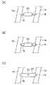
図2には本発明の第1実施形態に係る液滴吐出ヘッドが示されている。<First Embodiment>
FIG. 2 shows a droplet discharge head according to the first embodiment of the present invention.
図2に示すように、液滴吐出ヘッド10にはイジェクタ20が2次元状にマトリクス配列され、列間に液流方向の異なる共通流路14A、14Bが交互に配置され、それぞれ共通流路本流12A、12Bからインクが供給されている。 As shown in FIG. 2,
共通流路本流12A、12Bは各イジェクタ20に第1連通路16、第2連通路18を介してインクを供給する共通流路14A、14Bにインクを供給している。これによりイジェクタ20は第1連通路16、第2連通路18からそれぞれ逆方向の液流による背圧が作用する。 The
すなわち本実施形態においては隣接する共通流路14A、14Bでインク循環流の方向が互いに異なっている点、および各イジェクタ20に2つの連通路16、18が具備されており、それぞれが別個の共通流路14A、14B(インク循環流が逆方向の共通流路)と連結している点が特徴である。
That is, in the present embodiment, the direction of the ink circulation flow is different between the adjacent
加えて、隣接する共通流路14A/14Bでインク循環流の方向が逆になるように、共通流路本流12A、12Bもそれぞれ循環流ごとに独立しており、図2Aでは共通流路14A、14Bごとに1本ずつの共通流路本流12A、12Bが設けられている。
In addition, the
上記のような流路構造を採用することにより、2次元状に配列された全てのイジェクタ20に対して、作用する背圧をほぼ一定にすることが可能となる。 By adopting the above-described flow path structure, it is possible to make the back pressure acting on all the
例えばイジェクタ20Aに着目すると、第1連通路16は共通流路14Aの下流(低背圧)に接続されており、第2連通路18は共通流路14Bの上流(高背圧)に接続されている。従って、イジェクタ20Aの圧力室に作用する背圧は、2点(第1連通路16/共通流路14Aの接続箇所と、第2連通路18/共通流路14Bの接続箇所)の圧力の平均値となる。 For example, focusing on the
一方、イジェクタ20Bに着目すると、第1連通路16は共通流路14Aの上流(高背圧)に接続されており、第2連通路18は共通流路14Bの下流(低背圧)に接続されている。従って、イジェクタ20Bの圧力室に作用する背圧は、2点(第1連通路16/共通流路14Aの接続箇所と、第2連通路18/共通流路14Bの接続箇所)の圧力の平均値となり、これはイジェクタ20Aの圧力室に作用する背圧と等しくなる。 On the other hand, focusing on the
すなわち図2(B)に示すようにイジェクタ20A、20Bの圧力室に作用する背圧は共通流路14A/14Bの圧力P14A/P14Bの平均値であり、共通流路14A、14Bの一方が上流側で大きな圧力であれば他方は下流側で小さな圧力となるので、両者の平均値であるイジェクタ20の背圧は接続箇所にかかわらず一定の値となる。 That is, as shown in FIG. 2B, the back pressure acting on the pressure chambers of the
このように、隣接する共通流路14に逆方向のインク循環流を形成し、各イジェクタ20を両方の共通流路14と連結することによって、各イジェクタ20に作用する背圧をほぼ一定とすることが可能となる。 In this way, an ink circulation flow in the opposite direction is formed in the adjacent
<イジェクタ内のインク流>
図3には本発明の第1実施形態に係る液滴吐出ヘッドのイジェクタ内に発生するインク流が示されている。<Ink flow in ejector>
FIG. 3 shows an ink flow generated in the ejector of the droplet discharge head according to the first embodiment of the present invention.
図3に示すように、イジェクタ20の圧力室24を複数の連通路16/18によって共通流路14の複数箇所と連結した場合、連結箇所の圧力差によってイジェクタ20内にインク流が発生する(図中黒矢印)。 As shown in FIG. 3, when the
このインク流を有効活用すれば、圧力室24内部のインクを常に循環させることによってリフレッシュすることができ、圧力室24内における増粘インクの蓄積やインクの変質(色材の沈降など)を防止することが可能となる。すなわち圧力室24内にインクが長時間滞留することによって溶媒含有率の低下したインクが増粘し、あるいはインク中に分散していた色材が凝集/沈降などの変質を起こす虞があるが、常に圧力室24内のインクを流動させることで上記の事態を避けることができる。 If this ink flow is used effectively, the ink in the
本実施形態では、図3に示したように圧力室24に設けた2つの連通路16/18のうち、一方を圧力室24の後端近傍に、他方を圧力室24の先端(=ノズル22近傍)に設置することにより、圧力室24内部のインク循環を効率的に行うことができ、上記の効果を得やすくなる。 In the present embodiment, as shown in FIG. 3, of the two
なお、図3の黒矢印の太さで示したように、イジェクタ20内に発生するインク流の流量は、イジェクタ20の共通流路14への接続位置によって異なる。すなわち、共通流路14の上流近傍/下流近傍に接続されたイジェクタ20Aでは、共通流路14との連結箇所間(イジェクタ20の両端=連通路と連通路の間)に大きな圧力差があるため、イジェクタ20内に大きな流量が発生する。 As indicated by the thickness of the black arrow in FIG. 3, the flow rate of the ink flow generated in the
他方、共通流路14の中央付近に接続されたイジェクタ20Cでは、共通流路14との連結箇所間(イジェクタ20の両端=連通路と連通路の間)の圧力差が小さいため、イジェクタ20内には僅かなインク流しか発生しない。従って、イジェクタ20内のインク流による効果(上述)を得るためには、共通流路14の中央付近に接続されたイジェクタ20でも十分なインク流量が得られるように共通流路14との接続箇所を設定する必要がある。 On the other hand, in the
また、連通路16/18の流路抵抗が過小の場合には、黒矢印のインク流が支配的となり、共通流路14内に必要なインク流(白矢印)が得られなくなるため、連通路16/18の流路抵抗は共通流路14の流路抵抗に対して一定以上大きく設定する必要がある。 Further, when the flow path resistance of the
具体的には、連通路16/18の流路抵抗総和R1と共通流路14(各イジェクタ20間の部分)の流路抵抗R2の比(R2/R1)を10倍以上,より好ましくは1000倍以上に設定することが望ましい。 Specifically, the ratio (R2 / R1) of the total flow resistance R1 of the
<イジェクタと共通流路の接続>
図4には、本発明に係るイジェクタと共通流路の接続方法が示されている。<Connection between ejector and common flow path>
FIG. 4 shows a method for connecting an ejector and a common flow path according to the present invention.
第1実施形態(図2〜3)においては、溝形状の連通路16/18を介してイジェクタ20(圧力室24)と共通流路14を連結した(図4(A))が、連通路16/18の形状/形態はこれに限定されるものではない。 In the first embodiment (FIGS. 2 to 3), the ejector 20 (pressure chamber 24) and the
例えば、図4(B)に示す第2実施形態のようにイジェクタ20とは別個の部材に設けた穴として連通路16/18を設けてもよいし、図4(C)のように、イジェクタ20自体の両端部に設けた穴形状の連通路16/18を介してイジェクタ20と共通流路14を連結しても差し支えない。つまり、所望とする流路抵抗R1が得られる流路形状であれば、連通路16/18はあらゆる形状/形態を採ることが可能である。 For example, the
図4(c)に示す第3実施形態では、 2つの共通流路14間に架橋するようにイジェクタ20の圧力室24を配置し、穴形状の連通路16および連通路18を介して圧力室24と共通流路14を連結している。このような構造を採用することにより、部品点数の少ない単純なヘッド構造で、本発明を実施することが可能となる。 In the third embodiment shown in FIG. 4C, the
<断面>
図5には、本発明の第4実施形態に係る液滴吐出ヘッドを複数の金属プレートを積層して作成したイジェクタ部が示されている。<Cross section>
FIG. 5 shows an ejector unit in which a droplet discharge head according to a fourth embodiment of the present invention is formed by laminating a plurality of metal plates.
図5に示すように、液滴吐出ヘッド10の流路はウェットエッチング等により穿孔加工された複数のプレートを積層接合することにより形成される。 As shown in FIG. 5, the flow path of the
圧力室24の一方の壁面はピエゾ素子26と一体化された圧力板28が設けられ、図示しない制御部からの制御信号によりピエゾ素子26が駆動され、振動すると一体化された圧力板28もまた振動し、圧力室24内のインクを加圧する。 One wall surface of the
加圧されたインクはノズル22からインク滴となって吐出される。これにより消費された圧力室24内のインクは連通路16/18を経由して共通流路14から補充される。 The pressurized ink is ejected from the
図5のように圧力室24は連通路16および連通路18を介して共通流路14と連結されており、本実施形態では連通路16は穴形状、連通路18は溝形状として形成したが、前述のように所望とする流路抵抗R1を確保できれば、連通路16/18の形状は上記の穴形状や溝形状に限定されない。 As shown in FIG. 5, the
このとき共通流路14Aと共通流路14Bでは、インクの流れが逆方向になるように共通流路本流12と接続されており(図2参照)、例えば共通流路14A→連通路16→圧力室24→連通路18→共通流路14Bのような経路でインク循環流が形成される。 At this time, the
これによりイジェクタ20のリフィル特性を維持しながら、隣接する共通流路14に逆方向のインク循環流を形成し、各イジェクタ20を両方の共通流路14と連結することによって、各イジェクタ20に作用する背圧をほぼ一定とすることが可能となる。 Thus, while maintaining the refill characteristic of the
<他の実施形態>
図6には、本発明の第5実施形態に係る液滴吐出ヘッドを複数の金属プレートを積層して作成したイジェクタ部における共通流路と共通流路本流の接続形態が示されている。<Other embodiments>
FIG. 6 shows a connection form of a common flow path and a common flow path main flow in an ejector portion in which a droplet discharge head according to a fifth embodiment of the present invention is formed by laminating a plurality of metal plates.
図6に示すように、液滴吐出ヘッド10の流路はウェットエッチング等により穿孔加工された複数のプレートを積層接合することにより形成される点は第4実施形態と同様である。 As shown in FIG. 6, the flow path of the
本実施形態では、流れの方向が互いに異なる共通流路本流12Aおよび共通流路本流12Bが2階建て構造として液滴吐出ヘッド10の内部に形成され、イジェクタ20間に配置された共通流路14と共通流路連通路13Aまたは共通流路連通路13Bを介して接続されている。
In the present embodiment, a common flow path
上記のような構造を採ることにより、共通流路連通路13A/13Bの選択によって共通流路14内のインク流れ方向を任意に設定することが可能となり、図2に示したようなインク循環流を形成することが可能となる。この構造であれば液滴吐出方向(ノズル方向)から見た共通流路連通路13A/13Bの投影面積を共通流路連通路11の1本分に抑えることができるので、無理なく更なる高密度化を実現することができる。
By adopting the structure as described above, it becomes possible to arbitrarily set the ink flow direction in the
なお、液滴吐出ヘッド10内におけるインク循環流は、液滴吐出ヘッド10の外部に設けたポンプ(図示せず)等によって発生される。また、図6のように2階建て構造とせず図中において左右方向に配置した平面配置としてもよい。 The ink circulation flow in the
<まとめ>
以上のように、本発明に係る液滴吐出ヘッドは,複数設けられた連通路を介して,液の強制液流が形成された共通流路と複数箇所で連結された構成とすることでイジェクタの背圧ばらつき発生を防止し、画像品質の悪化を防ぐことができる。<Summary>
As described above, the droplet discharge head according to the present invention has an ejector having a configuration in which a plurality of communication paths are connected to a common flow path in which a forced liquid flow of liquid is formed through a plurality of communication paths. The occurrence of back pressure variation can be prevented, and deterioration of image quality can be prevented.
以上、本発明の実施例について記述したが、本発明は上記の実施例に何ら限定されるものではなく、本発明の要旨を逸脱しない範囲において種々なる態様で実施し得ることは言うまでもない。 As mentioned above, although the Example of this invention was described, it cannot be overemphasized that this invention is not limited to said Example at all, and can implement in a various aspect in the range which does not deviate from the summary of this invention.
また本発明は電気機械変換器(具体的にはピエゾアクチュエータや静電アクチュエータ)を用いた液滴吐出ヘッドだけでなく、サーマル方式など他の吐出原理を用いた液滴吐出ヘッドにも適用可能である。 The present invention can be applied not only to a droplet discharge head using an electromechanical transducer (specifically, a piezoelectric actuator or an electrostatic actuator) but also to a droplet discharge head using another discharge principle such as a thermal method. is there.
さらに、本発明の適用分野はインクジェットプリンタに限定されず、カラーフィルタ製造、半導体製造、各種成膜装置等の工業用液滴吐出装置を含め、あらゆる液滴吐出装置に適用することが可能である。特に工業用途では高粘度の液体を吐出するニーズが多いため、本発明を有効に利用することが可能である。 Furthermore, the field of application of the present invention is not limited to inkjet printers, and can be applied to any droplet discharge device, including industrial droplet discharge devices such as color filter manufacturing, semiconductor manufacturing, and various film forming apparatuses. . Particularly in industrial applications, there are many needs for discharging high-viscosity liquids, so that the present invention can be used effectively.
10 液滴吐出ヘッド
12 共通流路本流
13共通流路連通路
14 共通流路
16 連通路
18 連通路
20 イジェクタ
22 ノズル
24 圧力室
26 ピエゾ素子
28 振動板
以上DESCRIPTION OF
more than
Claims (8)
Translated fromJapanese隣接して配置され、互いに逆方向の液流が形成された第1の共通流路と、第2の共通流路と、を備え、
複数の前記イジェクタが前記第1の共通流路および前記第2の共通流路に沿って配列され、各々が前記イジェクタに設けられた2つの連通路を介して、前記第1の共通流路および前記第2の共通流路とにそれぞれ連結され、
前記第1の共通流路の上流側、かつ前記第2の共通流路の下流側に連結された前記イジェクタには、前記第1の共通流路から前記第2の共通流路に向けて液体が流れ、
前記第1の共通流路の下流側、かつ前記第2の共通流路の上流側に連結された前記イジェクタには、前記第2の共通流路から前記第1の共通流路に向けて液体が流れることを特徴とする液滴吐出ヘッド。A liquid droplet ejection head that pressurizes liquid in the pressure chamber by driving a pressure generating means provided in a pressure chamber in an ejector, and ejects liquid droplets from a nozzle that communicates with the pressure chamber;
A first common flow path disposed adjacent to each other and formed with liquid flows in opposite directions, and a second common flow path,
A plurality of the ejectors are arranged along the first common flow path and the second common flow path, and each of the first common flow path and the second common flow path is provided via two communication paths provided in the ejector. Respectively connected to the second common flow path ;
The ejector connected to the upstream side of the first common flow path and the downstream side of the second common flow path has a liquid flowing from the first common flow path toward the second common flow path. Flows,
The ejector connected to the downstream side of the first common flow path and the upstream side of the second common flow path has liquid flowing from the second common flow path toward the first common flow path. A liquid droplet ejection head characterized byflowing .
Priority Applications (3)
| Application Number | Priority Date | Filing Date | Title |
|---|---|---|---|
| JP2006340217AJP4872649B2 (en) | 2006-12-18 | 2006-12-18 | Droplet discharge head and droplet discharge apparatus |
| US11/899,201US8087758B2 (en) | 2006-12-18 | 2007-09-05 | Liquid droplet ejecting head and liquid droplet ejecting apparatus |
| CN2007101492840ACN101204876B (en) | 2006-12-18 | 2007-09-11 | Liquid droplet ejecting head and liquid droplet ejecting apparatus |
Applications Claiming Priority (1)
| Application Number | Priority Date | Filing Date | Title |
|---|---|---|---|
| JP2006340217AJP4872649B2 (en) | 2006-12-18 | 2006-12-18 | Droplet discharge head and droplet discharge apparatus |
Publications (3)
| Publication Number | Publication Date |
|---|---|
| JP2008149579A JP2008149579A (en) | 2008-07-03 |
| JP2008149579A5 JP2008149579A5 (en) | 2010-02-12 |
| JP4872649B2true JP4872649B2 (en) | 2012-02-08 |
Family
ID=39526623
Family Applications (1)
| Application Number | Title | Priority Date | Filing Date |
|---|---|---|---|
| JP2006340217AExpired - Fee RelatedJP4872649B2 (en) | 2006-12-18 | 2006-12-18 | Droplet discharge head and droplet discharge apparatus |
Country Status (3)
| Country | Link |
|---|---|
| US (1) | US8087758B2 (en) |
| JP (1) | JP4872649B2 (en) |
| CN (1) | CN101204876B (en) |
Families Citing this family (30)
| Publication number | Priority date | Publication date | Assignee | Title |
|---|---|---|---|---|
| US8463669B2 (en) | 2009-01-09 | 2013-06-11 | Ganart Technologies, Inc. | System for providing goods and services based on accrued but unpaid earnings |
| JP5569092B2 (en)* | 2010-03-26 | 2014-08-13 | セイコーエプソン株式会社 | Liquid ejecting head, liquid ejecting head unit, and liquid ejecting apparatus |
| JP5302259B2 (en)* | 2010-04-28 | 2013-10-02 | パナソニック株式会社 | Inkjet head and inkjet apparatus |
| EP2571696B1 (en) | 2010-05-21 | 2019-08-07 | Hewlett-Packard Development Company, L.P. | Fluid ejection device with circulation pump |
| US10132303B2 (en)* | 2010-05-21 | 2018-11-20 | Hewlett-Packard Development Company, L.P. | Generating fluid flow in a fluidic network |
| US9963739B2 (en) | 2010-05-21 | 2018-05-08 | Hewlett-Packard Development Company, L.P. | Polymerase chain reaction systems |
| US8540355B2 (en)* | 2010-07-11 | 2013-09-24 | Hewlett-Packard Development Company, L.P. | Fluid ejection device with circulation pump |
| US9090084B2 (en) | 2010-05-21 | 2015-07-28 | Hewlett-Packard Development Company, L.P. | Fluid ejection device including recirculation system |
| US9395050B2 (en) | 2010-05-21 | 2016-07-19 | Hewlett-Packard Development Company, L.P. | Microfluidic systems and networks |
| US8721061B2 (en) | 2010-05-21 | 2014-05-13 | Hewlett-Packard Development Company, L.P. | Fluid ejection device with circulation pump |
| BR112013000372B1 (en)* | 2010-07-28 | 2020-11-03 | Hewlett-Packard Development Company, L. P | fluid ejection assemblies |
| JP5422529B2 (en)* | 2010-09-16 | 2014-02-19 | 東芝テック株式会社 | Inkjet head |
| JP2012171255A (en)* | 2011-02-22 | 2012-09-10 | Kyocera Corp | Ink jet head, and recording device |
| WO2013162606A1 (en)* | 2012-04-27 | 2013-10-31 | Hewlett-Packard Development Company, L.P. | Fluid ejection device with two-layer tophat |
| JP2014044157A (en) | 2012-08-28 | 2014-03-13 | Ricoh Co Ltd | Optical sensor and image forming device |
| JP5657035B2 (en)* | 2013-01-21 | 2015-01-21 | 東芝テック株式会社 | Inkjet head and inkjet recording apparatus |
| CN106794696B (en)* | 2014-08-29 | 2018-07-27 | 京瓷株式会社 | Liquid ejection head and recording device using the liquid ejection head |
| JP7016208B2 (en)* | 2014-12-27 | 2022-02-04 | 株式会社リコー | Liquid discharge head, liquid discharge unit, liquid discharge device |
| US9944078B2 (en)* | 2015-01-23 | 2018-04-17 | Kyocera Corporation | Liquid discharge head and recording device using the same |
| US20180221873A1 (en)* | 2015-12-14 | 2018-08-09 | Hewlett-Packard Development Company, L.P. | Microfluid channel with developer port |
| JP7034586B2 (en)* | 2016-01-08 | 2022-03-14 | キヤノン株式会社 | Liquid discharge head and liquid discharge method |
| JP6135887B2 (en)* | 2016-04-19 | 2017-05-31 | セイコーエプソン株式会社 | Liquid ejecting head, liquid ejecting apparatus, and liquid ejecting method |
| CN114889328B (en)* | 2017-03-29 | 2024-04-19 | 京瓷株式会社 | Liquid ejection head, and recording device and recording method using the same |
| JP7020021B2 (en)* | 2017-09-20 | 2022-02-16 | ブラザー工業株式会社 | Liquid discharge device |
| WO2019130532A1 (en) | 2017-12-28 | 2019-07-04 | コニカミノルタ株式会社 | Ink jet head and ink jet recording apparatus |
| JP2019130872A (en) | 2018-02-02 | 2019-08-08 | 株式会社リコー | Liquid ejection head, liquid ejection unit, and device ejecting liquid |
| JP7047454B2 (en) | 2018-02-23 | 2022-04-05 | 株式会社リコー | Liquid discharge head, liquid discharge unit, liquid discharge device |
| JP7176199B2 (en)* | 2018-02-28 | 2022-11-22 | ブラザー工業株式会社 | LIQUID EJECTION HEAD AND LIQUID EJECTION APPARATUS |
| JP7031376B2 (en) | 2018-03-04 | 2022-03-08 | 株式会社リコー | Liquid discharge head, liquid discharge unit, liquid discharge device |
| JP7176282B2 (en)* | 2018-08-06 | 2022-11-22 | ブラザー工業株式会社 | liquid ejection head |
Family Cites Families (30)
| Publication number | Priority date | Publication date | Assignee | Title |
|---|---|---|---|---|
| US4835554A (en)* | 1987-09-09 | 1989-05-30 | Spectra, Inc. | Ink jet array |
| JPH02212147A (en)* | 1989-02-13 | 1990-08-23 | Seiko Epson Corp | Image forming method |
| JP2998764B2 (en)* | 1991-06-13 | 2000-01-11 | セイコーエプソン株式会社 | Ink jet print head, ink supply method, and air bubble removal method |
| JPH05220953A (en)* | 1992-02-14 | 1993-08-31 | Ricoh Co Ltd | Hot melt ink jet recorder |
| JP3158671B2 (en)* | 1992-07-07 | 2001-04-23 | セイコーエプソン株式会社 | Ink jet head and driving method thereof |
| JPH07164640A (en)* | 1993-12-15 | 1995-06-27 | Ricoh Co Ltd | Inkjet recording device |
| US6343857B1 (en)* | 1994-02-04 | 2002-02-05 | Hewlett-Packard Company | Ink circulation in ink-jet pens |
| US5565900A (en)* | 1994-02-04 | 1996-10-15 | Hewlett-Packard Company | Unit print head assembly for ink-jet printing |
| JPH08238772A (en) | 1995-03-07 | 1996-09-17 | Canon Inc | Inkjet recording head and inkjet recording device |
| TW365578B (en)* | 1995-04-14 | 1999-08-01 | Canon Kk | Liquid ejecting head, liquid ejecting device and liquid ejecting method |
| US5818485A (en)* | 1996-11-22 | 1998-10-06 | Xerox Corporation | Thermal ink jet printing system with continuous ink circulation through a printhead |
| US6286938B1 (en)* | 1999-02-17 | 2001-09-11 | Hitachi, Ltd. | Ink jet recording head and ink jet recording apparatus |
| US6244694B1 (en)* | 1999-08-03 | 2001-06-12 | Hewlett-Packard Company | Method and apparatus for dampening vibration in the ink in computer controlled printers |
| JP2001088297A (en)* | 1999-09-21 | 2001-04-03 | Fuji Xerox Co Ltd | Ink-jet recording heat, method and apparatus for ink-jet recording |
| GB0000368D0 (en)* | 2000-01-07 | 2000-03-01 | Xaar Technology Ltd | Droplet deposition apparatus |
| JP2002234175A (en) | 2001-02-08 | 2002-08-20 | Canon Inc | Method and apparatus for preventing ink thickening in liquid ejecting apparatus, and color filter manufacturing apparatus |
| US6685299B2 (en)* | 2001-05-31 | 2004-02-03 | Brother Kogyo Kabushiki Kaisha | Ink jet head |
| JP2003276189A (en)* | 2002-03-20 | 2003-09-30 | Fuji Photo Film Co Ltd | Liquid drop ejector and ink jet recording head |
| TW550233B (en)* | 2002-12-30 | 2003-09-01 | Ind Tech Res Inst | Micro fluidic module |
| GB0316584D0 (en)* | 2003-07-16 | 2003-08-20 | Xaar Technology Ltd | Droplet deposition apparatus |
| EP1518683B1 (en)* | 2003-09-24 | 2008-03-19 | FUJIFILM Corporation | Droplet discharge head and inkjet recording apparatus |
| JP2005225182A (en) | 2004-02-16 | 2005-08-25 | Sony Corp | Liquid ejector and its control method |
| JP4315018B2 (en)* | 2004-03-01 | 2009-08-19 | ソニー株式会社 | Liquid discharge head and liquid discharge apparatus |
| SG114773A1 (en)* | 2004-03-01 | 2005-09-28 | Sony Corp | Liquid ejection head and liquid ejection device |
| JP2005329595A (en)* | 2004-05-19 | 2005-12-02 | Fuji Photo Film Co Ltd | Liquid droplet jet head and image forming apparatus |
| JP4617798B2 (en)* | 2004-09-22 | 2011-01-26 | 富士ゼロックス株式会社 | Ink jet recording head and ink jet recording apparatus |
| JP4774742B2 (en)* | 2005-01-11 | 2011-09-14 | 富士ゼロックス株式会社 | Ink jet recording head and ink jet recording apparatus |
| JP4641440B2 (en)* | 2005-03-23 | 2011-03-02 | キヤノン株式会社 | Ink jet recording head and method of manufacturing the ink jet recording head |
| JP4855992B2 (en)* | 2007-03-30 | 2012-01-18 | 富士フイルム株式会社 | Liquid circulation device, image forming apparatus, and liquid circulation method |
| AT507142B1 (en)* | 2008-08-14 | 2011-05-15 | Durst Phototechnik Digital Technology Gmbh | INK SUPPLY SYSTEM AND METHOD FOR CLEANING AN INK SUPPLY SYSTEM |
- 2006
- 2006-12-18JPJP2006340217Apatent/JP4872649B2/ennot_activeExpired - Fee Related
- 2007
- 2007-09-05USUS11/899,201patent/US8087758B2/ennot_activeExpired - Fee Related
- 2007-09-11CNCN2007101492840Apatent/CN101204876B/ennot_activeExpired - Fee Related
Also Published As
| Publication number | Publication date |
|---|---|
| JP2008149579A (en) | 2008-07-03 |
| US8087758B2 (en) | 2012-01-03 |
| US20080143793A1 (en) | 2008-06-19 |
| CN101204876A (en) | 2008-06-25 |
| CN101204876B (en) | 2011-03-30 |
Similar Documents
| Publication | Publication Date | Title |
|---|---|---|
| JP4872649B2 (en) | Droplet discharge head and droplet discharge apparatus | |
| KR102383356B1 (en) | Liquid ejection head and liquid ejection apparatus | |
| KR101347144B1 (en) | Restrictor with structure for preventing back flow and inkjet head having the same | |
| KR101257840B1 (en) | Inkjet head having piezoelectric actuator for restrictor | |
| JP5668482B2 (en) | Liquid ejecting head and liquid ejecting apparatus | |
| EP2186642B1 (en) | Liquid discharge head and liquid discharge method | |
| CN101376284B (en) | Liquid ejection head, inkjet printing apparatus, and liquid ejection method | |
| JP5753739B2 (en) | Droplet discharge head | |
| JP4323947B2 (en) | Inkjet recording head | |
| JP5029395B2 (en) | Droplet discharge device | |
| JP2010188572A (en) | Inkjet recording head, and cleaning method therefor | |
| JP5578794B2 (en) | Liquid ejecting head and liquid ejecting apparatus | |
| JP6135887B2 (en) | Liquid ejecting head, liquid ejecting apparatus, and liquid ejecting method | |
| JP2004090504A (en) | Liquid droplet jetting head and liquid droplet jetting apparatus | |
| JP2008246919A (en) | Recording head | |
| JP2006130916A (en) | Piezoelectric inkjet printhead with one-way shutter | |
| US6609784B2 (en) | Ink jet recording device and a method for designing the same | |
| US11607882B2 (en) | Liquid ejection module | |
| JP7358153B2 (en) | liquid dispensing module | |
| JP5863337B2 (en) | Inkjet recording head | |
| US11312135B2 (en) | Liquid ejecting head | |
| JP6264580B2 (en) | Liquid jet head | |
| JP4562177B2 (en) | Liquid discharge recording head and liquid discharge recording apparatus | |
| JP5531481B2 (en) | Liquid discharge head | |
| JP2005125696A (en) | Inkjet recording head |
Legal Events
| Date | Code | Title | Description |
|---|---|---|---|
| A521 | Request for written amendment filed | Free format text:JAPANESE INTERMEDIATE CODE: A523 Effective date:20091217 | |
| A621 | Written request for application examination | Free format text:JAPANESE INTERMEDIATE CODE: A621 Effective date:20091217 | |
| A131 | Notification of reasons for refusal | Free format text:JAPANESE INTERMEDIATE CODE: A131 Effective date:20110802 | |
| A521 | Request for written amendment filed | Free format text:JAPANESE INTERMEDIATE CODE: A523 Effective date:20110930 | |
| TRDD | Decision of grant or rejection written | ||
| A01 | Written decision to grant a patent or to grant a registration (utility model) | Free format text:JAPANESE INTERMEDIATE CODE: A01 Effective date:20111025 | |
| A01 | Written decision to grant a patent or to grant a registration (utility model) | Free format text:JAPANESE INTERMEDIATE CODE: A01 | |
| A61 | First payment of annual fees (during grant procedure) | Free format text:JAPANESE INTERMEDIATE CODE: A61 Effective date:20111107 | |
| FPAY | Renewal fee payment (event date is renewal date of database) | Free format text:PAYMENT UNTIL: 20141202 Year of fee payment:3 | |
| R150 | Certificate of patent or registration of utility model | Ref document number:4872649 Country of ref document:JP Free format text:JAPANESE INTERMEDIATE CODE: R150 Free format text:JAPANESE INTERMEDIATE CODE: R150 | |
| LAPS | Cancellation because of no payment of annual fees | ||
| S533 | Written request for registration of change of name | Free format text:JAPANESE INTERMEDIATE CODE: R313533 | |
| R370 | Written measure of declining of transfer procedure | Free format text:JAPANESE INTERMEDIATE CODE: R370 |