JP4872244B2 - Chemical reaction cartridge - Google Patents
Chemical reaction cartridgeDownload PDFInfo
- Publication number
- JP4872244B2 JP4872244B2JP2005163824AJP2005163824AJP4872244B2JP 4872244 B2JP4872244 B2JP 4872244B2JP 2005163824 AJP2005163824 AJP 2005163824AJP 2005163824 AJP2005163824 AJP 2005163824AJP 4872244 B2JP4872244 B2JP 4872244B2
- Authority
- JP
- Japan
- Prior art keywords
- target molecule
- cartridge
- chip
- chemical reaction
- substrate
- Prior art date
- Legal status (The legal status is an assumption and is not a legal conclusion. Google has not performed a legal analysis and makes no representation as to the accuracy of the status listed.)
- Expired - Fee Related
Links
Images


Classifications
- B—PERFORMING OPERATIONS; TRANSPORTING
- B01—PHYSICAL OR CHEMICAL PROCESSES OR APPARATUS IN GENERAL
- B01L—CHEMICAL OR PHYSICAL LABORATORY APPARATUS FOR GENERAL USE
- B01L3/00—Containers or dishes for laboratory use, e.g. laboratory glassware; Droppers
- B01L3/50—Containers for the purpose of retaining a material to be analysed, e.g. test tubes
- B01L3/502—Containers for the purpose of retaining a material to be analysed, e.g. test tubes with fluid transport, e.g. in multi-compartment structures
- B01L3/5027—Containers for the purpose of retaining a material to be analysed, e.g. test tubes with fluid transport, e.g. in multi-compartment structures by integrated microfluidic structures, i.e. dimensions of channels and chambers are such that surface tension forces are important, e.g. lab-on-a-chip
- B01L3/502715—Containers for the purpose of retaining a material to be analysed, e.g. test tubes with fluid transport, e.g. in multi-compartment structures by integrated microfluidic structures, i.e. dimensions of channels and chambers are such that surface tension forces are important, e.g. lab-on-a-chip characterised by interfacing components, e.g. fluidic, electrical, optical or mechanical interfaces
- B—PERFORMING OPERATIONS; TRANSPORTING
- B01—PHYSICAL OR CHEMICAL PROCESSES OR APPARATUS IN GENERAL
- B01L—CHEMICAL OR PHYSICAL LABORATORY APPARATUS FOR GENERAL USE
- B01L2300/00—Additional constructional details
- B01L2300/06—Auxiliary integrated devices, integrated components
- B01L2300/0627—Sensor or part of a sensor is integrated
- B01L2300/0636—Integrated biosensor, microarrays
- B—PERFORMING OPERATIONS; TRANSPORTING
- B01—PHYSICAL OR CHEMICAL PROCESSES OR APPARATUS IN GENERAL
- B01L—CHEMICAL OR PHYSICAL LABORATORY APPARATUS FOR GENERAL USE
- B01L2300/00—Additional constructional details
- B01L2300/06—Auxiliary integrated devices, integrated components
- B01L2300/0681—Filter
- B—PERFORMING OPERATIONS; TRANSPORTING
- B01—PHYSICAL OR CHEMICAL PROCESSES OR APPARATUS IN GENERAL
- B01L—CHEMICAL OR PHYSICAL LABORATORY APPARATUS FOR GENERAL USE
- B01L2300/00—Additional constructional details
- B01L2300/08—Geometry, shape and general structure
- B01L2300/0809—Geometry, shape and general structure rectangular shaped
- B01L2300/0825—Test strips
- B—PERFORMING OPERATIONS; TRANSPORTING
- B01—PHYSICAL OR CHEMICAL PROCESSES OR APPARATUS IN GENERAL
- B01L—CHEMICAL OR PHYSICAL LABORATORY APPARATUS FOR GENERAL USE
- B01L2300/00—Additional constructional details
- B01L2300/08—Geometry, shape and general structure
- B01L2300/0861—Configuration of multiple channels and/or chambers in a single devices
- B01L2300/087—Multiple sequential chambers
- B—PERFORMING OPERATIONS; TRANSPORTING
- B01—PHYSICAL OR CHEMICAL PROCESSES OR APPARATUS IN GENERAL
- B01L—CHEMICAL OR PHYSICAL LABORATORY APPARATUS FOR GENERAL USE
- B01L2300/00—Additional constructional details
- B01L2300/08—Geometry, shape and general structure
- B01L2300/0861—Configuration of multiple channels and/or chambers in a single devices
- B01L2300/0877—Flow chambers
- B—PERFORMING OPERATIONS; TRANSPORTING
- B01—PHYSICAL OR CHEMICAL PROCESSES OR APPARATUS IN GENERAL
- B01L—CHEMICAL OR PHYSICAL LABORATORY APPARATUS FOR GENERAL USE
- B01L2400/00—Moving or stopping fluids
- B01L2400/04—Moving fluids with specific forces or mechanical means
- B01L2400/0403—Moving fluids with specific forces or mechanical means specific forces
- B01L2400/0415—Moving fluids with specific forces or mechanical means specific forces electrical forces, e.g. electrokinetic
- B01L2400/0421—Moving fluids with specific forces or mechanical means specific forces electrical forces, e.g. electrokinetic electrophoretic flow
- B—PERFORMING OPERATIONS; TRANSPORTING
- B01—PHYSICAL OR CHEMICAL PROCESSES OR APPARATUS IN GENERAL
- B01L—CHEMICAL OR PHYSICAL LABORATORY APPARATUS FOR GENERAL USE
- B01L2400/00—Moving or stopping fluids
- B01L2400/04—Moving fluids with specific forces or mechanical means
- B01L2400/0475—Moving fluids with specific forces or mechanical means specific mechanical means and fluid pressure
- B01L2400/0481—Moving fluids with specific forces or mechanical means specific mechanical means and fluid pressure squeezing of channels or chambers
- B—PERFORMING OPERATIONS; TRANSPORTING
- B01—PHYSICAL OR CHEMICAL PROCESSES OR APPARATUS IN GENERAL
- B01L—CHEMICAL OR PHYSICAL LABORATORY APPARATUS FOR GENERAL USE
- B01L7/00—Heating or cooling apparatus; Heat insulating devices
- B01L7/52—Heating or cooling apparatus; Heat insulating devices with provision for submitting samples to a predetermined sequence of different temperatures, e.g. for treating nucleic acid samples
Landscapes
- Chemical & Material Sciences (AREA)
- Health & Medical Sciences (AREA)
- Dispersion Chemistry (AREA)
- Analytical Chemistry (AREA)
- General Health & Medical Sciences (AREA)
- Hematology (AREA)
- Clinical Laboratory Science (AREA)
- Chemical Kinetics & Catalysis (AREA)
- Apparatus Associated With Microorganisms And Enzymes (AREA)
Description
Translated fromJapanese本発明は、外力を加えた際の変形によって内部の送液を行うことで化学反応を生じさせる化学反応用カートリッジに関する。 The present invention relates to a chemical reaction cartridge that generates a chemical reaction by feeding an internal liquid by deformation when an external force is applied.
スライドガラス型の生体高分子マイクロアレイを挿入した上で、外力を加えて変形させることで内部の送液を行い、生体高分子をマイクロアレイに固定化するカートリッジが提案されている(特許文献1参照)。 A cartridge has been proposed in which a slide glass-type biopolymer microarray is inserted, and an internal force is deformed by applying an external force to deform the cartridge so that the biopolymer is immobilized on the microarray (see Patent Document 1). .
近年、スライドガラス型のマイクロアレイに代るものとして、多数の異なる標的分子の検出部位が高密度に集積された標的分子検出用チップが開発されている。このような標的分子検出用チップは検出可能な標的分子の数に比して、極めてコンパクトに形成されている。したがって、このような標的分子検出用チップに対応するコンパクトな化学反応用カートリッジが望まれている。 In recent years, as an alternative to a slide glass type microarray, a target molecule detection chip in which detection sites for many different target molecules are integrated at high density has been developed. Such a target molecule detection chip is formed extremely compact compared to the number of target molecules that can be detected. Therefore, a compact chemical reaction cartridge corresponding to such a target molecule detection chip is desired.
また、標的分子検出用チップの1類型として、その厚み方向に溶液を貫通可能な構造の貫通型チップが開発されている。しかし、上記従来のカートリッジでは、このような貫通型チップに対応できない。ポンプ等を用いた装置を用いて溶液を貫通型チップに通し、ハイブリダイゼーションを行うシステムが開発されているが、装置が大型となりシステムも高価なものとなる。 As one type of target molecule detection chip, a penetrating chip having a structure capable of penetrating a solution in the thickness direction has been developed. However, the conventional cartridge cannot cope with such a penetrating chip. A system for performing hybridization by passing a solution through a penetrating chip using an apparatus using a pump or the like has been developed, but the apparatus becomes large and the system becomes expensive.
本発明の目的は、標的分子検出用チップを用いた標的分子の検出に対応可能で、コンパクトな化学反応用カートリッジを提供することにある。 An object of the present invention is to provide a compact cartridge for chemical reaction that can cope with detection of a target molecule using a target molecule detection chip.
本発明の化学反応用カートリッジは、基板とこれに接着された弾性部材とを備え、外力を加えた際の変形によって前記基板の平面方向に内部の送液を行うことで化学反応を生じさせる化学反応用カートリッジにおいて、前記基板と前記弾性部材の間に形成され、外力を加えた際の前記弾性部材の変形によって前記基板の平面方向に内部の送液が行われる第1の流路と、前記基板と前記弾性部材の間に形成され、外力を加えた際の前記弾性部材の変形によって前記基板の平面方向に内部の送液が行われ、前記第1の流路と同一平面内に位置する第2の流路と、標的分子を含む溶液がその厚み方向に貫通可能とされた貫通孔が形成された貫通型の標的分子検出用チップと、この標的分子検出用チップをその検出部位の配列平面が前記基板の平面方向と一致するように前記化学反応用カートリッジ内に保持する収納部と、前記標的分子検出用チップの前記貫通孔が開口する一の平面の側に形成された供給部と、前記標的分子検出用チップの、前記供給部の側の前記一の平面に対向する他の平面の側に形成された排出部と、前記排出部と前記第2の流路とを接続する接続路と、を備え、前記第1の流路、前記供給部、前記貫通孔、前記排出部、前記接続路および前記第2の流路が、密閉状態が維持された空間を形成するように順次接続され、外力を加えた際の変形時の圧力によって、前記貫通型チップの前記貫通孔を前記溶液が前記第1の流路から前記第2の流路に向けて通過するように構成されたことを特徴とする。
この化学反応用カートリッジによれば、化学反応用カートリッジに外力を加えた際の化学反応用カートリッジの変形によって貫通型チップの内部を溶液が通過するので、外力を加えることで貫通型チップによる標的分子の検出を行える。
The chemical reaction cartridge of the present invention includes a substrate and an elastic member bonded to the substrate, and a chemical reaction is generated by sending an internal liquid in the plane direction of the substrate by deformation when an external force is applied. In the reaction cartridge, afirst flow path formed between the substrate and the elastic member, in which an internal liquid is fed in a plane direction of the substrate by deformation of the elastic member when an external force is applied, Formed between the substrate and the elastic member, the inner member is fed in the plane direction of the substrate by deformation of the elastic member when an external force is applied, and is located in the same plane as the first flow path. A second flow channel, a penetrating target molecule detection chip in which a through-hole that allows a solution containingthe target molecule to penetrate in the thickness direction is formed, and the target molecule detection chip is arranged in the detection site plane plane sidesof the substrate A storage unit that is held in the chemical reaction cartridge so as to match, a supply unit that is formed on the one plane side where the through hole of the target molecule detection chip opens, and the target molecule detection chip of the said discharge portion formed on the side of the other plane facing the one plane side of the supply unit, anda connection passage for connecting the second flow path and the discharge portion,wherein The first flow path, the supply section, the through hole, the discharge section, the connection path, and the second flow path are sequentially connected so as to form a space in which a sealed state is maintained, and an external force is applied. The solution is configured such that the solution passes through the through-hole of the through-type chip fromthe first flow path towardthe second flow path by a pressure at the time of deformation.
According to this chemical reaction cartridge, the solution passes through the penetration chip by deformation of the chemical reaction cartridge when an external force is applied to the chemical reaction cartridge. Can be detected.
前記標的分子検出用チップは、DNA、RNA、タンパク質、代謝物のうちいずれかを標的分子として検出してもよい。 The target molecule detection chip may detect any one of DNA, RNA, protein, and metabolite as a target molecule.
前記標的分子検出用チップをその厚み方向に挟み込む一対の電極を備え、前記電極により前記標的分子検出用チップ内部の荷電分子に電界を印加するように構成してもよい。A pair of electrodes sandwiching the target molecule detection chip in its thickness direction may be provided, and an electric field may be applied to charged molecules inside the target molecule detection chip by the electrodes.
本発明の化学反応用カートリッジによれば、標的分子検出用チップ全体を前記化学反応用カートリッジの内部に収容したので、種々の形式の標的分子検出用チップに対応できる。 According to the chemical reaction cartridge of the present invention, since the entire target molecule detection chip is accommodated in the chemical reaction cartridge, it can be used for various types of target molecule detection chips.
また、本発明の化学反応用カートリッジによれば、化学反応用カートリッジに外力を加えた際の化学反応用カートリッジの変形によって貫通型標的分子検出用チップの内部を溶液が通過するので、外力を加えることで貫通型標的分子検出用チップによる標的分子の検出を行える。 Further, according to the chemical reaction cartridge of the present invention, the solution passes through the inside of the penetrating target molecule detection chip due to the deformation of the chemical reaction cartridge when an external force is applied to the chemical reaction cartridge. Thus, the target molecule can be detected by the penetrating target molecule detection chip.
以下、本発明による化学反応用カートリッジの実施例について説明する。 Examples of the chemical reaction cartridge according to the present invention will be described below.
以下、図1〜図8を参照して、本発明による化学反応用カートリッジの実施例1について説明する。 Hereinafter, Example 1 of the cartridge for chemical reaction according to the present invention will be described with reference to FIGS.
図1は本実施例の化学反応用カートリッジの構成を示す平面図、図2は図1のII−II線における断面図である。 FIG. 1 is a plan view showing the structure of the chemical reaction cartridge of this embodiment, and FIG. 2 is a cross-sectional view taken along the line II-II in FIG.
図1および図2に示すように、本実施例の化学反応用カートリッジは、基板1と、基板1に重ね合わされる弾性部材2とを備える。 As shown in FIGS. 1 and 2, the chemical reaction cartridge of this embodiment includes a
弾性部材2の裏面(図2において下面)には、その表面(図2において上面)側に凹んだ所定形状の凹部が形成されている。この凹部は、カートリッジ基板1と弾性部材2との間に空間を生み出すことで、図1および図2に示すように、溶液を収容する室21,22,23、後述する標的分子検出用チップ3へ溶液等を供給するための供給部24、および、流路25,26,27,28を構成する。図1に示すように、流路25、室21、流路26、室22、流路27および供給部24は順次連通されている。 On the back surface (lower surface in FIG. 2) of the elastic member 2, a concave portion having a predetermined shape is formed that is recessed toward the front surface (upper surface in FIG. 2). This recess creates a space between the
上記凹部以外の領域では、カートリッジ基板1と弾性部材2とは互いに接着されている。このため、凹部に収容された溶液がカートリッジ内で密閉され、外部への漏れが防止される。 In the region other than the concave portion, the
図1および図2に示すように、基板1には、標的分子検出用チップ3が収容される収容部11と、標的分子検出用チップ3の裏側(図2において下側)に設けられ、標的分子検出用チップ3から排出される溶液を収容する排出部12と、が形成されている。また、弾性部材2の裏面には、標的分子検出用チップ3を支持する支持部材4が固定されている。収容部11に収容された標的分子検出用チップ3は、カートリッジ基板1および支持部材4に接着されて、カートリッジ内部に固定される。このような構造により、標的分子検出用チップ3の周囲からの、標的分子検出用チップ3の厚み方向の溶液の漏れを防ぎつつ、標的分子検出用チップ3をカートリッジ内部で固定している。また、図2に示すように、カートリッジ基板1の排出部12は流路28に連通されている。 As shown in FIGS. 1 and 2, the
標的分子検出用チップ3はハイブリダイゼーションにより標的分子を検出する、貫通型チップである。 The target
図3は標的分子検出用チップ3の構造を示す図であり、図3(a)は斜視図、図3(b)は図3(a)のB−B線における断面図である。図3(a)および図3(b)に示すように、標的分子検出用チップ3では、個々の標的分子に対応するプローブが固定された検出部位31が2次元的に配置され、各検出部位31が隔壁32により区画されている。各検出部位31は標的分子検出用チップ3の厚み方向(図3(b)において上下方向)に貫通する溶液中の標的分子をハイブリダイゼーションにより検出する。 FIG. 3 is a diagram showing the structure of the target
次に、上記カートリッジにおける溶液移送の動作を説明する。図4は溶液移送時の操作を示す図である。 Next, the operation of transferring the solution in the cartridge will be described. FIG. 4 is a diagram illustrating an operation during solution transfer.
カートリッジに形成された室21には、予め検査対象となる溶液が注入される。溶液の注入は、流路25を介して注射針を差し込むことで行われる。流路25には弾性体からなる栓(不図示)が密閉状態で取り付けられており、溶液注入時には注射針を栓に突刺する。溶液注入後、注射針を引き抜くと栓の針孔が塞がり、密閉状態が確保される。 A solution to be inspected is injected into the
次に、図4および図1に示すように、一定間隔で設けられたローラ51およびローラ52により弾性部材2を基板1に向けて押し付け、ローラ51およびローラ52を右方向に移動させる。このような操作により、室21に注入された溶液が、流路26、室22、流路27を介して供給部24に送り込まれる。さらに図4に示すように、溶液は、供給部24から標的分子検出用チップ3の各検出部位31を下向きに貫通し、排出部12および流路28を介して室23に到達する。 Next, as shown in FIGS. 4 and 1, the elastic member 2 is pressed against the
次に、ローラ51およびローラ52を弾性部材2に押し付けたまま、図4において左右方向に、所定回数往復移動させる。このような操作により、溶液を室22および室26の間で往復移送し、標的分子検出用チップ3の検出部位31を複数回通過させる。これにより、ハイブリダイゼーションのために必要とされる検出部材31に対する溶液の接触の充分な機会を与える。また、標的分子以外の分子による誤ったハイブリダイゼーションを低減する。なお、ハイブリダイゼーションの条件として適切であれば、ローラ51およびローラ52の往復移動を省略することもできる。 Next, the
図4に示すように、ハイブリダイゼーションを行う間、ヒータHTを用いて溶液の温度をハイブリダイゼーションに適した値に保持してもよい。 As shown in FIG. 4, during the hybridization, the temperature of the solution may be maintained at a value suitable for hybridization using a heater HT.
このようなハイブリダイゼーションのための操作を行った後、所定の読取装置等を用いて標的分子検出用チップ3においてハイブリダイゼーションした標的分子の検出を行う。標的分子検出用チップ3をカートリッジから取り出すことなく、カートリッジ内部で標的分子の検出を行うようにしてもよいし、標的分子検出用チップ3をカートリッジから取り外した後に標的分子の検出を行うようにしてもよい。 After performing such an operation for hybridization, the target molecules detected in the target
以上のように、本実施例によれば、カートリッジ内で標的分子検出用チップによるハイブリダイゼーションを行うことができる。また、標的分子検出用チップを貫通するように溶液が移送されるので、貫通型チップに対応できる。 As described above, according to this embodiment, hybridization with the target molecule detection chip can be performed in the cartridge. Further, since the solution is transferred so as to penetrate the target molecule detection chip, it can be applied to the penetration type chip.
貫通型チップとして、種々のタイプのものを使用できる。例えば、オリンパス株式会社の多孔質フィルタにプローブを固相化したチップ(商品名:PAMマイクロアレイシステム)や、繊維型チップ(例えば、三菱レイヨン株式会社の商品「ジェノパール」(登録商標))等を使用できる。 Various types of penetrating chips can be used. For example, a chip (trade name: PAM microarray system) in which a probe is solid-phased on a porous filter manufactured by Olympus Corporation, a fiber chip (for example, a product “Genopal” (registered trademark) manufactured by Mitsubishi Rayon Co., Ltd.), etc. Can be used.
また、図5に示すように、検査対象溶液を収容する採取部61、検査対象溶液と混合する前処理液を予め収容する前処理液保存部62、洗浄液を予め収容する洗浄液保存部63を設け、これらを流路62によって接続してもよい。 Further, as shown in FIG. 5, a
この場合には、ローラの移動により採取部61の検査対象溶液と、前処理液保存部62の前処理液を送り出すことで両者を混合し、ラベル化が行われる。次いでチップにおけるハイブリダイゼーションが行われる。また、ハイブリダイゼーション後には、ローラの移動により洗浄液保存部63が排出され、ハイブリダイズしなかった分子を溶液とともに洗い流す。その後に、チップにおいてハイブリダイゼーションした標的分子の検出を行う。なお、特開2004−226068号公報に、このような操作の詳細が記載されている。 In this case, by moving the roller, the solution to be inspected in the
本実施例では、標的分子検出用チップ3を接着により固定しているが、図6に示すように、標的分子検出用チップ3をカートリッジの構成部材に嵌合させて固定してもよい。図6の例では、シール部71〜74を介して標的分子検出用チップ3を支持することで、標的分子検出用チップ3の周囲からの、標的分子検出用チップ3の厚み方向の溶液の漏れを防ぎつつ、標的分子検出用チップ3をカートリッジ内部で機械的に固定している。 In this embodiment, the target
チップにおいてハイブリダイゼーションした標的分子の検出方法として、例えば、レーザ等を用いた蛍光測定に基づく方法等の光を用いた検出方法や、電流を用いた検出方法が用いられる。電流を用いた検出方法が使用される場合に、外部から電流をカートリッジ内部のチップに供給するためのコネクタを、カートリッジに設けてもよい。この場合、コネクタはカートリッジの密閉状態を維持する状態で取り付けられる。 As a method for detecting a target molecule hybridized on a chip, for example, a detection method using light such as a method based on fluorescence measurement using a laser or the like, or a detection method using an electric current is used. When a detection method using an electric current is used, a connector for supplying an electric current from the outside to a chip inside the cartridge may be provided on the cartridge. In this case, the connector is attached while maintaining the sealed state of the cartridge.
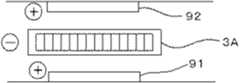
図7は、チップ3に電界をかけて荷電分子を泳動させハイブリダイゼーションを促進するための電極をカートリッジに形成する例を示している。図7の例では、電極81が基板1Bの内面に、電極82が弾性部材2Bの内面に、それぞれ設けられている。電極81および電極82は、カートリッジに設けられたコネクタを介して外部の電源と接続可能とされる。この場合、電極81および電極82間に印加する電圧を繰り返し反転することで、電界を反転させハイブリダイゼーションを促進することができる。また、誤ったハイブリダイゼーションを低減できる。図8に示すように、チップ3Aに導電性を与え、チップ3A自身を電極として使用することもできる。この場合には、電極91、電極92とともにチップ3Aは、カートリッジに設けられたコネクタを介して外部の電源と接続可能とされる。 FIG. 7 shows an example in which electrodes are formed on the cartridge for promoting hybridization by applying an electric field to the
一般的に、ハイブリダイゼーションを促進するための電極は溶液と直接接触するため、劣化が生じやすく、洗浄等の作業が煩雑なものとなりがちである。しかし、本実施例では、1回の検査のみで廃棄されるカートリッジに電極を設けているため、電極の劣化やメンテナンスの問題が生じないという利点がある。 In general, an electrode for promoting hybridization is in direct contact with a solution, so that it is likely to be deteriorated, and operations such as washing tend to be complicated. However, in this embodiment, since the electrode is provided on the cartridge that is discarded only by one inspection, there is an advantage that the problem of electrode deterioration and maintenance does not occur.
上記実施例では、貫通型チップを使用する例を示しているが、平面型チップを使用する場合にも本発明を適用可能である。 In the above embodiment, an example in which a penetration type chip is used is shown, but the present invention can also be applied to the case of using a planar type chip.
以下、図9を参照して、本発明による化学反応用カートリッジの実施例2について説明する。本実施例は、平面型チップを用いた化学反応用カートリッジを例示するものである。 Hereinafter, Example 2 of the cartridge for chemical reaction according to the present invention will be described with reference to FIG. This example illustrates a cartridge for chemical reaction using a planar chip.
図9(a)は本実施例の化学反応用カートリッジを示す平面図、図9(b)は、図9(a)のIXb−IXb線における断面図である。 FIG. 9A is a plan view showing the chemical reaction cartridge of this embodiment, and FIG. 9B is a cross-sectional view taken along the line IXb-IXb in FIG. 9A.
図9(a)および図9(b)に示すように、本実施例の化学反応用カートリッジは、基板101と、基板101に重ね合わされる弾性部材102とを備える。 As shown in FIGS. 9A and 9B, the chemical reaction cartridge of this embodiment includes a
弾性部材102の裏面(図9(b)において下面)には、その表面(図9(b)において上面)側に凹んだ所定形状の凹部が形成されている。この凹部は、カートリッジ基板101と弾性部材102との間に空間を生み出すことで、溶液を収容する室121,122,123、後述するチップ103を収容する収容部124、および、流路125,126,127,128を構成する。図1に示すように、流路125、室121、流路126、室122、流路127、収容部124、流路128および室123は順次連通されている。 On the back surface (lower surface in FIG. 9B) of the
上記凹部以外の領域では、カートリッジ基板101と弾性部材102とは互いに接着されている。このため、凹部に収容された溶液がカートリッジ内で密閉され、外部への漏れが防止される。 In the region other than the concave portion, the
図9(a)および図9(b)に示すように、基板101には、標的分子検出用チップ103が収容される。 As shown in FIGS. 9A and 9B, the target
チップ103はハイブリダイゼーションにより標的分子を検出する、平面型チップである。チップ103の表面(図9(b)において上面)には、個々の標的分子に対応するプローブが固定された検出部位が2次元的に配置されている。 The
次に、上記カートリッジにおける溶液移送の動作を説明する。 Next, the operation of transferring the solution in the cartridge will be described.
カートリッジに形成された室121には、予め検査対象となる溶液が注入される。溶液の注入は、流路125を介して注射針を差し込むことで行われる。流路125には弾性体からなる栓(不図示)が密閉状態で取り付けられており、溶液注入時には注射針を栓に突刺する。溶液注入後、注射針を引き抜くと栓の針孔が塞がり、密閉状態が確保される。 A solution to be inspected is injected into the
次に、実施例1と同様、ローラにより弾性部材102を基板101に向けて押し付けつつ、ローラを右方向に移動させる。このような操作により、室121に注入された溶液が、流路126、室126、流路127を介して収容部124に送り込まれる。 Next, as in the first embodiment, the roller is moved rightward while pressing the
収容部124に送り込まれた溶液により、チップ103におけるハイブリダイゼーションが行われる。実施例1と同様、ローラを往復移動させることで、溶液をチップ103上に繰り返し供給してもよい。 Hybridization in the
このようなハイブリダイゼーションのための操作を行った後、所定の読取装置等を用いてチップ103においてハイブリダイゼーションした標的分子の検出を行う。チップ103をカートリッジから取り出すことなく、カートリッジ内部で標的分子の検出を行うようにしてもよいし、チップ103をカートリッジから取り外した後に標的分子の検出を行うようにしてもよい。 After performing such an operation for hybridization, a target molecule hybridized in the
以上のように、本実施例によれば、カートリッジ内で平面型チップによるハイブリダイゼーションを行うことができる。なお、特開2004−226068号公報では、スライドガラス型のマイクロアレイによる検出を行っており、本発明のように標的検出用チップ全体を収容したカートリッジを示すものではない。本発明では、チップ全体を収容することにより、完全な密封が可能になる。しかし、上記公報に開示されたハイブリダイゼーションのための操作は本発明に対して同様に適用できる。 As described above, according to the present embodiment, hybridization with a planar chip can be performed in the cartridge. In Japanese Patent Application Laid-Open No. 2004-226068, detection by a slide glass type microarray is performed, and a cartridge containing the entire target detection chip as in the present invention is not shown. In the present invention, complete sealing is possible by accommodating the entire chip. However, the procedure for hybridization disclosed in the above publication can be similarly applied to the present invention.
また、実施例1と同様、検査対象溶液を収容する採取部や、洗浄液を予め収容する洗浄液保存部を設けてもよい。 Further, similarly to the first embodiment, a collecting unit for storing the solution to be inspected and a cleaning liquid storage unit for storing the cleaning liquid in advance may be provided.
さらに、チップ103の固定方法、標的分子の検出方法、電極をカートリッジに形成する点、等については、本実施例に対し、実施例1で示した構成を適用できる。 Furthermore, the configuration shown in Example 1 can be applied to the present example with respect to the method for fixing the
上記各実施形態において、標的分子の種類は限定されない。例えば、標的分子としてDNA、RNA、タンパク質、各種代謝物を挙げることができる。また、生体高分子の検出に限定されず、一般のクロマトグラフィーにも適用できる。 In each of the above embodiments, the type of target molecule is not limited. For example, examples of the target molecule include DNA, RNA, protein, and various metabolites. Moreover, it is not limited to the detection of biopolymers, but can be applied to general chromatography.
本発明の適用範囲は上記実施形態に限定されることはない。本発明は、外力を加えた際の変形によって内部の送液を行うことで化学反応を生じさせる化学反応用カートリッジに対し、広く適用することができる。 The scope of application of the present invention is not limited to the above embodiment. The present invention can be widely applied to a cartridge for chemical reaction that generates a chemical reaction by feeding an internal liquid by deformation when an external force is applied.
3 標的分子検出用チップ
81 電極
82 電極
91 電極
92 電極
103 標的分子検出用チップ
3 Target Molecule Detection Chip 81
Claims (3)
Translated fromJapanese前記基板と前記弾性部材の間に形成され、外力を加えた際の前記弾性部材の変形によって前記基板の平面方向に内部の送液が行われる第1の流路と、
前記基板と前記弾性部材の間に形成され、外力を加えた際の前記弾性部材の変形によって前記基板の平面方向に内部の送液が行われ、前記第1の流路と同一平面内に位置する第2の流路と、
標的分子を含む溶液がその厚み方向に貫通可能とされた貫通孔が形成された貫通型の標的分子検出用チップと、
この標的分子検出用チップをその検出部位の配列平面が前記基板の平面方向と一致するように前記化学反応用カートリッジ内に保持する収納部と、
前記標的分子検出用チップの前記貫通孔が開口する一の平面の側に形成された供給部と、
前記標的分子検出用チップの、前記供給部の側の前記一の平面に対向する他の平面の側に形成された排出部と、
前記排出部と前記第2の流路とを接続する接続路と、
を備え、
前記第1の流路、前記供給部、前記貫通孔、前記排出部、前記接続路および前記第2の流路が、密閉状態が維持された空間を形成するように順次接続され、
外力を加えた際の変形時の圧力によって、前記貫通型チップの前記貫通孔を前記溶液が前記第1の流路から前記第2の流路に向けて通過するように構成されたことを特徴とする化学反応用カートリッジ。In a chemical reaction cartridge that includes a substrate and an elastic member bonded thereto, and causes a chemical reaction by performing internal liquid feeding in the planar direction of the substrate by deformation when an external force is applied,
A first flow path formed between the substrate and the elastic member, in which an internal liquid is sent in the plane direction of the substrate by deformation of the elastic member when an external force is applied;
Formed between the substrate and the elastic member, the internal member is fed in the plane direction of the substrate by deformation of the elastic member when an external force is applied, and is located in the same plane as the first flow path. A second flow path to
A penetrating target molecule detection chip in which a through-hole in which a solution containing the target molecule is allowed to penetrate in the thickness direction; and
A storage unit for holding the target molecule detection chip in the chemical reaction cartridge so that the arrangement plane of the detection site matchesthe plane direction of the substrate;
A supply unit formed on the side of one plane where the through hole of the target molecule detection chip opens;
A discharge part formed on the other plane side of the target molecule detection chip opposite to the one plane on the supply part side;
A connection path connecting the discharge portion and the second flow path;
With
The first flow path, the supply section, the through hole, the discharge section, the connection path, and the second flow path are sequentially connected so as to form a space in which a sealed state is maintained,
The solution is configured so that the solution passes through the through-hole of the through-type chip fromthe first channel towardthe secondchannel by a pressure at the time of deformation when an external force is applied. A cartridge for chemical reaction.
Priority Applications (4)
| Application Number | Priority Date | Filing Date | Title |
|---|---|---|---|
| JP2005163824AJP4872244B2 (en) | 2005-06-03 | 2005-06-03 | Chemical reaction cartridge |
| EP06011407AEP1728555A2 (en) | 2005-06-03 | 2006-06-01 | Cartridge for chemical reaction |
| CNB2006100833453ACN100436600C (en) | 2005-06-03 | 2006-06-02 | Cartridge for chemical reaction |
| US11/446,225US20060275813A1 (en) | 2005-06-03 | 2006-06-05 | Cartridge for chemical reaction |
Applications Claiming Priority (1)
| Application Number | Priority Date | Filing Date | Title |
|---|---|---|---|
| JP2005163824AJP4872244B2 (en) | 2005-06-03 | 2005-06-03 | Chemical reaction cartridge |
Related Child Applications (1)
| Application Number | Title | Priority Date | Filing Date |
|---|---|---|---|
| JP2009282795ADivisionJP5482174B2 (en) | 2009-12-14 | 2009-12-14 | Chemical reaction cartridge system |
Publications (2)
| Publication Number | Publication Date |
|---|---|
| JP2006337238A JP2006337238A (en) | 2006-12-14 |
| JP4872244B2true JP4872244B2 (en) | 2012-02-08 |
Family
ID=37011923
Family Applications (1)
| Application Number | Title | Priority Date | Filing Date |
|---|---|---|---|
| JP2005163824AExpired - Fee RelatedJP4872244B2 (en) | 2005-06-03 | 2005-06-03 | Chemical reaction cartridge |
Country Status (4)
| Country | Link |
|---|---|
| US (1) | US20060275813A1 (en) |
| EP (1) | EP1728555A2 (en) |
| JP (1) | JP4872244B2 (en) |
| CN (1) | CN100436600C (en) |
Families Citing this family (9)
| Publication number | Priority date | Publication date | Assignee | Title |
|---|---|---|---|---|
| KR100843146B1 (en)* | 2006-12-20 | 2008-07-02 | 삼성전자주식회사 | Biochip kit and biosample test method |
| EP2465609B1 (en) | 2007-06-21 | 2016-12-28 | Gen-Probe Incorporated | Method for mixing the contents of a detection chamber |
| JP1628116S (en) | 2012-10-24 | 2019-04-01 | ||
| US20140322706A1 (en) | 2012-10-24 | 2014-10-30 | Jon Faiz Kayyem | Integrated multipelx target analysis |
| CN107866286A (en) | 2013-03-15 | 2018-04-03 | 金马克诊断股份有限公司 | Systems, methods, and apparatus for manipulating deformable fluid containers |
| US9498778B2 (en) | 2014-11-11 | 2016-11-22 | Genmark Diagnostics, Inc. | Instrument for processing cartridge for performing assays in a closed sample preparation and reaction system |
| USD881409S1 (en) | 2013-10-24 | 2020-04-14 | Genmark Diagnostics, Inc. | Biochip cartridge |
| US10005080B2 (en) | 2014-11-11 | 2018-06-26 | Genmark Diagnostics, Inc. | Instrument and cartridge for performing assays in a closed sample preparation and reaction system employing electrowetting fluid manipulation |
| US9598722B2 (en) | 2014-11-11 | 2017-03-21 | Genmark Diagnostics, Inc. | Cartridge for performing assays in a closed sample preparation and reaction system |
Family Cites Families (13)
| Publication number | Priority date | Publication date | Assignee | Title |
|---|---|---|---|---|
| US4673657A (en)* | 1983-08-26 | 1987-06-16 | The Regents Of The University Of California | Multiple assay card and system |
| US6309602B1 (en)* | 1993-11-01 | 2001-10-30 | Nanogen, Inc. | Stacked, reconfigurable system for electrophoretic transport of charged materials |
| CN1115174C (en)* | 1999-02-12 | 2003-07-23 | 复旦大学 | Biological chip on electric conductive silicon glass carrier and preparation thereof |
| CN1223851C (en)* | 1999-10-20 | 2005-10-19 | 内田和彦 | Gene detection chip, detection device and detection method |
| JP2001127242A (en)* | 1999-10-22 | 2001-05-11 | Seiko Epson Corp | Semiconductor chip, multi-chip package, semiconductor device, electronic device, and manufacturing method thereof |
| CA2364381C (en)* | 1999-12-22 | 2009-03-10 | Gene Logic, Inc. | Flow-thru chip cartridge, chip holder, system and method thereof |
| US7524459B2 (en)* | 2002-01-24 | 2009-04-28 | California Institute Of Technology In Pasadena | Optoelectronic and microfluidic integration for miniaturized spectroscopic devices |
| US20040137607A1 (en)* | 2003-01-09 | 2004-07-15 | Yokogawa Electric Corporation | Biochip cartridge |
| JP4006639B2 (en)* | 2003-01-20 | 2007-11-14 | 横河電機株式会社 | Biochip cartridge |
| JP4399766B2 (en)* | 2003-07-04 | 2010-01-20 | 横河電機株式会社 | Chemical reaction cartridge |
| US7854897B2 (en)* | 2003-05-12 | 2010-12-21 | Yokogawa Electric Corporation | Chemical reaction cartridge, its fabrication method, and a chemical reaction cartridge drive system |
| JP2004340895A (en)* | 2003-05-19 | 2004-12-02 | Olympus Corp | Inspection container and detection device of organism-related substance |
| JP2005055316A (en)* | 2003-08-05 | 2005-03-03 | Olympus Corp | Solution removing method and solution absorbing tool in living body related material reaction test |
- 2005
- 2005-06-03JPJP2005163824Apatent/JP4872244B2/ennot_activeExpired - Fee Related
- 2006
- 2006-06-01EPEP06011407Apatent/EP1728555A2/ennot_activeWithdrawn
- 2006-06-02CNCNB2006100833453Apatent/CN100436600C/ennot_activeExpired - Fee Related
- 2006-06-05USUS11/446,225patent/US20060275813A1/ennot_activeAbandoned
Also Published As
| Publication number | Publication date |
|---|---|
| US20060275813A1 (en) | 2006-12-07 |
| CN1880438A (en) | 2006-12-20 |
| JP2006337238A (en) | 2006-12-14 |
| EP1728555A2 (en) | 2006-12-06 |
| CN100436600C (en) | 2008-11-26 |
Similar Documents
| Publication | Publication Date | Title |
|---|---|---|
| CN100436600C (en) | Cartridge for chemical reaction | |
| JP4489088B2 (en) | Nucleic acid detection device | |
| US8137512B2 (en) | Process for analyzing sample by capillary electrophoresis method | |
| JP6053231B2 (en) | Electrophoresis medium container and electrophoresis apparatus | |
| EP2711415B1 (en) | Assay cartridges and methods of using the same | |
| WO2007111274A1 (en) | Nucleic acid detection cassette and nucleic acid detection apparatus | |
| JP2016532111A (en) | Fluid system for delivering reagents to a flow cell | |
| JP5208826B2 (en) | Fine channel device | |
| van den Brink et al. | Parallel single‐cell analysis microfluidic platform | |
| JP6151359B2 (en) | Capillary electrophoresis device | |
| JP5482174B2 (en) | Chemical reaction cartridge system | |
| JP4261546B2 (en) | Electrophoresis apparatus and electrophoresis method | |
| CN106010949A (en) | Sequencing Device and Method for Operating a Sequencing Device | |
| US10620157B2 (en) | Single point detection type microfluidic isoelectric focusing assay and chips using the same | |
| JP2016052252A (en) | Nucleic acid detection cassette | |
| JPWO2009128346A1 (en) | Electrode module | |
| JP2008157948A (en) | Biochip kit and biospecimen inspection method | |
| JP2000310615A (en) | Chip for electrophoresis, its manufacture, electrophoresis device and chargeable material separating method using the same | |
| JP4006639B2 (en) | Biochip cartridge | |
| JP6855154B2 (en) | Nucleic acid detection cassette | |
| KR20210002276A (en) | integrated cartridge | |
| JP4723891B2 (en) | Hybridization cartridge, hybridization apparatus, and hybridization method | |
| Jia et al. | An electronic tongue system with automatic sample mixing function for long-term in-situ monitoring of chemical reactions | |
| JP2024110055A (en) | Nucleic acid testing device and its use | |
| KR20160135695A (en) | cartridge for containing specimen sample |
Legal Events
| Date | Code | Title | Description |
|---|---|---|---|
| A621 | Written request for application examination | Free format text:JAPANESE INTERMEDIATE CODE: A621 Effective date:20071211 | |
| A977 | Report on retrieval | Free format text:JAPANESE INTERMEDIATE CODE: A971007 Effective date:20091015 | |
| A131 | Notification of reasons for refusal | Free format text:JAPANESE INTERMEDIATE CODE: A131 Effective date:20091020 | |
| A521 | Written amendment | Free format text:JAPANESE INTERMEDIATE CODE: A523 Effective date:20091214 | |
| A131 | Notification of reasons for refusal | Free format text:JAPANESE INTERMEDIATE CODE: A131 Effective date:20100617 | |
| A521 | Written amendment | Free format text:JAPANESE INTERMEDIATE CODE: A523 Effective date:20100812 | |
| A131 | Notification of reasons for refusal | Free format text:JAPANESE INTERMEDIATE CODE: A131 Effective date:20110215 | |
| A521 | Written amendment | Free format text:JAPANESE INTERMEDIATE CODE: A523 Effective date:20110415 | |
| TRDD | Decision of grant or rejection written | ||
| A01 | Written decision to grant a patent or to grant a registration (utility model) | Free format text:JAPANESE INTERMEDIATE CODE: A01 Effective date:20111025 | |
| A01 | Written decision to grant a patent or to grant a registration (utility model) | Free format text:JAPANESE INTERMEDIATE CODE: A01 | |
| A61 | First payment of annual fees (during grant procedure) | Free format text:JAPANESE INTERMEDIATE CODE: A61 Effective date:20111107 | |
| FPAY | Renewal fee payment (event date is renewal date of database) | Free format text:PAYMENT UNTIL: 20141202 Year of fee payment:3 | |
| R150 | Certificate of patent or registration of utility model | Free format text:JAPANESE INTERMEDIATE CODE: R150 | |
| LAPS | Cancellation because of no payment of annual fees |