JP4871909B2 - Object recognition apparatus and object recognition method - Google Patents
Object recognition apparatus and object recognition methodDownload PDFInfo
- Publication number
- JP4871909B2 JP4871909B2JP2008115681AJP2008115681AJP4871909B2JP 4871909 B2JP4871909 B2JP 4871909B2JP 2008115681 AJP2008115681 AJP 2008115681AJP 2008115681 AJP2008115681 AJP 2008115681AJP 4871909 B2JP4871909 B2JP 4871909B2
- Authority
- JP
- Japan
- Prior art keywords
- object recognition
- image
- manhole
- unit
- information
- Prior art date
- Legal status (The legal status is an assumption and is not a legal conclusion. Google has not performed a legal analysis and makes no representation as to the accuracy of the status listed.)
- Expired - Fee Related
Links
Images


Classifications
- G—PHYSICS
- G01—MEASURING; TESTING
- G01C—MEASURING DISTANCES, LEVELS OR BEARINGS; SURVEYING; NAVIGATION; GYROSCOPIC INSTRUMENTS; PHOTOGRAMMETRY OR VIDEOGRAMMETRY
- G01C21/00—Navigation; Navigational instruments not provided for in groups G01C1/00 - G01C19/00
- G01C21/26—Navigation; Navigational instruments not provided for in groups G01C1/00 - G01C19/00 specially adapted for navigation in a road network
- G—PHYSICS
- G06—COMPUTING OR CALCULATING; COUNTING
- G06T—IMAGE DATA PROCESSING OR GENERATION, IN GENERAL
- G06T5/00—Image enhancement or restoration
- G06T5/80—Geometric correction
- G—PHYSICS
- G06—COMPUTING OR CALCULATING; COUNTING
- G06T—IMAGE DATA PROCESSING OR GENERATION, IN GENERAL
- G06T7/00—Image analysis
- G06T7/20—Analysis of motion
- G06T7/254—Analysis of motion involving subtraction of images
- G—PHYSICS
- G06—COMPUTING OR CALCULATING; COUNTING
- G06V—IMAGE OR VIDEO RECOGNITION OR UNDERSTANDING
- G06V20/00—Scenes; Scene-specific elements
- G06V20/50—Context or environment of the image
- G06V20/56—Context or environment of the image exterior to a vehicle by using sensors mounted on the vehicle
- G06V20/588—Recognition of the road, e.g. of lane markings; Recognition of the vehicle driving pattern in relation to the road
- G—PHYSICS
- G08—SIGNALLING
- G08G—TRAFFIC CONTROL SYSTEMS
- G08G1/00—Traffic control systems for road vehicles
- G08G1/09—Arrangements for giving variable traffic instructions
- G08G1/0962—Arrangements for giving variable traffic instructions having an indicator mounted inside the vehicle, e.g. giving voice messages
- G08G1/09623—Systems involving the acquisition of information from passive traffic signs by means mounted on the vehicle
- G—PHYSICS
- G06—COMPUTING OR CALCULATING; COUNTING
- G06T—IMAGE DATA PROCESSING OR GENERATION, IN GENERAL
- G06T2207/00—Indexing scheme for image analysis or image enhancement
- G06T2207/30—Subject of image; Context of image processing
- G06T2207/30248—Vehicle exterior or interior
- G06T2207/30252—Vehicle exterior; Vicinity of vehicle
- G06T2207/30256—Lane; Road marking
- G—PHYSICS
- G08—SIGNALLING
- G08G—TRAFFIC CONTROL SYSTEMS
- G08G1/00—Traffic control systems for road vehicles
- G08G1/16—Anti-collision systems
- G08G1/165—Anti-collision systems for passive traffic, e.g. including static obstacles, trees
Landscapes
- Engineering & Computer Science (AREA)
- Physics & Mathematics (AREA)
- General Physics & Mathematics (AREA)
- Radar, Positioning & Navigation (AREA)
- Theoretical Computer Science (AREA)
- Remote Sensing (AREA)
- Multimedia (AREA)
- Computer Vision & Pattern Recognition (AREA)
- Automation & Control Theory (AREA)
- Image Analysis (AREA)
- Traffic Control Systems (AREA)
- Image Processing (AREA)
- Navigation (AREA)
Description
Translated fromJapanese本発明は、画像を用いて物体を検出する技術に関する。 The present invention relates to a technique for detecting an object using an image.
自車両に搭載された撮像装置からの撮像画像から、路面上の物体を検出し、相対的な自車位置を判断するような技術が知られている。 A technique is known in which an object on a road surface is detected from a captured image from an imaging device mounted on the host vehicle, and the relative position of the host vehicle is determined.
例えば、引用文献1に記載された発明では、自車両に搭載された撮像装置を用いて、ストロボが点灯時と非点灯時との画像を撮像し、これらの画像を比較することにより光反射標識を検出するような技術が記載されている。
しかしながら、特許文献1に記載の技術では、ストロボを車両に搭載しなければならないため、車両の機材積載量が増加してしまう。また、ストロボ点灯時および非点灯時の撮像タイミングにおいて自車位置が大きく異なる場合には、画像の比較が困難となる可能性があった。 However, with the technique described in Patent Document 1, since the strobe must be mounted on the vehicle, the amount of equipment loaded on the vehicle increases. In addition, when the vehicle position is greatly different at the imaging timing when the strobe is lit and when the strobe is not lit, it may be difficult to compare images.
そこで本発明では、ストロボが不要でかつ簡易な構成で路面上の物体を検出することが可能な技術を提供することを目的とする。 Therefore, an object of the present invention is to provide a technique that does not require a strobe and can detect an object on a road surface with a simple configuration.
前記課題を解決するために、本発明の物体認識装置は、外部からの光によって生じる画像間の差分を用いて、路面の物体を検出する技術を提供する。
例えば、移動体に搭載される撮像手段と、前記撮像手段が異なる時点で撮像した画像を、垂直方向から見下ろす合成画像(俯瞰画像)にそれぞれ変換する画像生成手段と、複数の前記合成画像を比較して、対応する領域を検出する検出手段と、前記対応する領域のうち輝度値の差異が大きい領域に対して円形検出処理を行い、円形のマンホールを認識する認識手段と、を備えることを特徴とする。
また例えば、前記対応する領域のうち輝度値の差異が大きい領域に対して四角形検出処理を行い、四角形のマンホールを認識する認識手段と、を備えることを特徴とする。
In order to solve the above-described problem, the object recognition apparatus of the present invention provides a technique for detecting an object on a road surface using a difference between images generated by light from the outside.
For example, an imaging unit mounted on a moving body, an image generation unit that converts an image captured at a different time by the imaging unit into a composite image (overhead image) looking down from the vertical direction, and a plurality of the composite images are compared. And detecting means for detecting acorresponding area; and recognition means for performing circular detection processing on an area having a large difference in luminance value among the corresponding areas and recognizing a circular manhole. And
Further, for example, the image processing apparatus includes: a recognition unit that performs a quadrangle detection process on a region having a large difference in luminance value among the corresponding regions, and recognizes a quadrangle manhole.
以上のように、本発明の物体認識装置は、ストロボが不要でかつ簡易な構成で路面上の物体を認識することが可能な技術を提供することができる。 As described above, the object recognition apparatus of the present invention can provide a technology that does not require a strobe and can recognize an object on a road surface with a simple configuration.
以下、本発明を実施するための最良の形態について、図面を参照して説明する。 The best mode for carrying out the present invention will be described below with reference to the drawings.
<第一の実施形態>
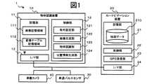
図1は、本願の第一の実施形態にかかる物体認識システム1の機能構成を示すブロック図である。<First embodiment>
FIG. 1 is a block diagram showing a functional configuration of an object recognition system 1 according to the first embodiment of the present application.
図示するように、物体認識システム1は、物体認識装置10と、カーナビゲーション装置20と、車速パルスセンサ30と、車載カメラ40と、を含んでいる。 As illustrated, the object recognition system 1 includes an
まず、カーナビゲーション装置20について説明する。なお、物体認識装置10とカーナビゲーション装置20とは、同一機器である一体型としてもよい。 First, the
カーナビゲーション装置20は、例えば、GPS(Global Positioning System;全地球測位システム)や、車速パルスおよびジャイロ等の自立航法装置を利用して自車両の位置を検出し、目的地への走行経路案内を行う装置である。 The
カーナビゲーション装置20は、記憶部21と、制御部22と、GPS受信部23と、インターフェース部24(以下、I/F部と称する)と、を備えている。 The
記憶部21は、全国の道路地図である地図データ210を予め記憶する。地図データ210は、例えば、図2に示すような構成のデータベースである。 The memory |
図2は、地図データ210の概略図である。地図データ210は、メッシュ状に区分された地域単位の地図情報211の集合である。 FIG. 2 is a schematic diagram of the
地図情報211とは、所定の地域内における、交差点および車線数や幅員が変更する点であるノードと、隣接するノードを連結するベクトルであるリンクと、の接続関係を表す情報である。各リンクは、リンクテーブル212によって管理される。 The
リンクテーブル212に格納される情報としては、一般的に次のようなものが挙げられる。例えば、リンクID;リンク両端(開始ノード・終了ノード)の座標;距離・方向・幅員等の特徴情報等である。 The information stored in the link table 212 generally includes the following information. For example, link ID; coordinates of link both ends (start node / end node); feature information such as distance, direction, width, and the like.
ここで、本実施形態にかかるリンクテーブル212は、上記に加えて、さらにマンホール情報213を有する。マンホール情報213とは、リンク内に存在するマンホールの識別子であるマンホールID214aと、マンホールの位置を特定する座標情報214bと、マンホールの種別を特定する種別情報214cと、マンホールのサイズを特定するサイズ情報214dと、を格納する情報である。 Here, the link table 212 according to the present embodiment further includes
具体的に、座標情報214bは、道路上に存在するマンホールの位置座標を、緯度および経度によって示す。種別情報214cは、例えば、マンホールの規格や形状、模様等を示す情報である。サイズ情報214dとは、例えば、円形のマンホールであれば直径や円周等、四角形のものであれば各辺の長さ等を示す情報である。 Specifically, the
以上に説明したようなマンホール情報213は、制御部22によって、物体認識装置10へと出力される。 The
制御部22は、自車両の周辺に存在するマンホールのマンホール情報213を特定し、I/F部24を介して物体認識装置10へと出力する。 The
具体的に、制御部22は、一定時間ごとに自車両の現在位置を中心として所定の範囲内、かつ、現在位置するリンクから接続される一繋がりの道路上に存在するマンホール情報213を検出して、これを物体認識装置10の条件設定部121へと出力する。マンホール情報が検出されなかった場合には、非検出信号を出力する。 Specifically, the
なお、制御部22は、自車両の進行方向を判断して、進行先の一定範囲内に存在するマンホールのマンホール情報213のみを抽出し、出力してもよい。また、カーナビゲーション装置20が経路案内を実行中の場合には、制御部22は、誘導先の経路上で一定範囲内に存在するマンホールのマンホール情報213のみを抽出してもよい。 The
また、制御部22は、物体認識装置10から出力される位置情報に協調して、自車位置を補正する。 Further, the
GPS受信部23は、GPS(Global Positioning System)衛星からの信号を受信する。 The
また、カーナビゲーション装置20は、この他に、道路に敷設されたビーコンや各地のFM放送局を介して、VICS(Vehicle Information and Communication System)センタから配信される道路交通情報を受信するVICS受信部等を備えていてもよい。 In addition to this, the
I/F部24は、物体認識装置10と通信を行うためのインターフェースであり、どのような通信方式を利用するものであってもよい。 The I /
物体認識装置10は、記憶部11と、制御部12と、I/F部13と、を備える。 The
記憶部11は、画像記憶領域111と、変換テーブル記憶領域112と、を有する。 The
画像記憶領域111は、車載カメラ40より出力されるフレーム画像と、フレーム画像より生成される俯瞰画像と、を記憶する。図3(a)および(b)に、フレーム画像および俯瞰画像の概略図を示す。 The
フレーム画像とは、車載カメラ40よりフレームレートに従って出力される撮像画像であり(図3(a)90A・90B参照)、俯瞰画像とは、画像生成部122が生成するフレーム画像を垂直方向に見下ろした画像(天空から垂直に地上面を見た場合の平面図;図3(b)91A・91B参照)である。これらは、画像生成部122により取得および生成され、画像記憶領域111に格納される。 The frame image is a captured image output according to the frame rate from the in-vehicle camera 40 (see 90A and 90B in FIG. 3A), and the bird's-eye view image looks down on the frame image generated by the
変換テーブル記憶領域112は、撮像画像(フレーム画像)から俯瞰画像を生成するために必要な変換テーブル(図示しない)を記憶する。変換テーブルとは、例えば、フレーム画像の各画素の座標位置と、俯瞰画像の各画素の座標位置と、を対応付け、ここに角度差やレンズの歪曲収差を補正するための補正パラメータを配したものである。補正パラメータとは、例えば、カメラの設置位置、設置角度、レンズ歪み、CCDサイズ等であり、レンズの光学特性やカメラの設定等に基づいて一意に決定される。なお、変換テーブルは、I/F部13を介して、他の装置から取得してもよい。 The conversion
制御部12は、デジタル画像処理条件を設定する条件設定部121と、車載カメラからの画像を俯瞰画像に変換する画像生成部122と、俯瞰画像に含まれる金属物を検出する物体認識部123と、金属物からの相対的な自車両の位置を特定する位置情報生成部124と、を有する。 The
条件設定部121は、画像記憶領域111に蓄積されたフレーム画像および当該画像の撮像環境に基づいて、画像生成部122の実行する前処理の内容を設定する。具体的に、条件設定部121は、カーナビゲーション装置20からマンホール情報213を受け付けると、まず、画像生成部122に処理の開始を要求する。 The
なお、条件設定部121は、カーナビゲーション装置20から周囲に存在するマンホール情報213の非検出信号を受信した場合には、画像生成部122へ処理の終了を要求する。 In addition, the
さらに、画像生成部122が処理を開始して新たなフレーム画像を取得すると、条件設定部121は、車速パルスセンサ30からのパルス信号に基づいて、現時点の車速を検出する。さらに、条件設定部121は、携帯電話ネットワーク等の無線通信網を利用し、サーバから天候・時刻等の環境情報を取得する。そして、画像生成部122の実行する前処理条件や、物体認識部123の実行する画像処理に関する設定を行う。 Furthermore, when the
ここで、画像生成部122の実行する前処理とは、フィルタリングやガンマ補正等、デジタル画像処理の一環である。 Here, the preprocessing executed by the
例えば、条件設定部121は、画面上のノイズ量を算出し、ノイズ量が多い場合には、画像生成部122の実行する前処理段階でノイズ除去処理(各種平滑化フィルタによるフィルタリング)の必要性を判断し、画像生成部122に実行させるか否かを決定する。 For example, the
また例えば、撮像環境が悪天候や夜間等で、フレーム画像の輝度値が全体的に低い場合には、条件設定部121は、ガンマ補正強度を決定するパラメータの設定を行う。 For example, when the imaging environment is bad weather, at night, or the like and the luminance value of the frame image is low overall, the
さらに、条件設定部121は、外乱光のためハレーションが発生している領域を判断する。 Furthermore, the
ハレーションは、後続車のヘッドライト等によって撮像画像の一定の領域に引き起こされるものであるため、条件設定部121は、夜間に一定時間、所定の輝度値以上の値を示す画素が存在する場合、これをハレーション領域として特定する。 Since halation is caused in a certain region of the captured image by a headlight of a subsequent vehicle, the
具体的に、条件設定部121は、最新のフレーム画像の輝度値と、過去の一定期間のフレーム画像の輝度値と、を比較して、連続的に所定の値以上の輝度値を有する領域が存在するか否かを検出する。上記のような領域がフレーム画像に存在する場合には、条件設定部121は、当該領域にマスク処理を施す。 Specifically, the
ここで、マスク処理とは、後段の物体認識部123の実行する認識処理の対象とならないマスク領域を設定するものである。例えば、フレーム画像をブロックに分割し、ブロックごとに1ビット長のマスクデータを設ける。そして、ハレーションが発生していると判断されるブロックのマスクデータにフラグを付与し、マスク領域としてラベリングする。 Here, the mask process is to set a mask area that is not the target of the recognition process executed by the
なお、環境情報は、カーナビゲーション装置20から現在地点を取得して、その周辺の情報のみを取得してもよいし、カーナビゲーション装置20が直接サーバから周辺の情報を取得して、条件設定部121へ出力するような構成としてもよい。 The environment information may be obtained by acquiring the current location from the
画像生成部122は、条件設定部121から処理の開始を要求されると、フレーム画像から俯瞰画像を生成する。具体的に、画像生成部122はまず、車載カメラ40より出力されるフレーム画像を取得して、画像記憶領域111に時系列順に蓄積する。そして、フレーム画像に前処理を施した後、変換テーブルを利用して垂直方向から見下ろした俯瞰画像(天空から地上面を見た場合の平面図)を生成する。生成した俯瞰画像は、時系列順に画像記憶領域111へと格納される。 When requested to start processing by the
なお、フレーム画像は、車載カメラ40のフレームレートに従って出力されるが、例えば、フレームレートが車速によって変化し、画像生成部122が常に一定の距離範囲を撮像したフレーム画像を得られるような構成としてもよい。また、フレームレートに関わらず、一定の距離間隔ごとにこれを取得してもよい。 The frame image is output in accordance with the frame rate of the in-
また、フレーム画像に施される前処理は、必ずしも全画面に実行する必要はない。例えば、他車により隠蔽されることが少なく、かつ、マンホールが適切な大きさで撮像される可能性が大きい領域である対象領域900(図3(a)のフレーム画像90A参照)を予め設定しておき、当該領域のみを以降の処理の対象とすることも可能である。 Further, the preprocessing applied to the frame image does not necessarily have to be executed on the entire screen. For example, a target region 900 (see the frame image 90A in FIG. 3A) that is a region that is less likely to be concealed by another vehicle and that is likely to be imaged with an appropriate size is set in advance. In addition, it is possible to set only the area as a target of subsequent processing.
物体認識部123は、俯瞰画像どうしを比較して、俯瞰画像中に含まれるマンホールを認識する。 The
ここで、マンホールの認識手法について、図3(a)、図3(b)および図4を参照しながら説明する。図4は、夜間に街灯60が点灯する道路を自車両が走行する場合の、車載カメラ40の撮像画像についての説明図である。 Here, the manhole recognition method will be described with reference to FIGS. 3 (a), 3 (b), and 4. FIG. FIG. 4 is an explanatory diagram of a captured image of the in-
図4に示すように、街灯60からマンホール50への光の入射角θ1と、車載カメラ40からマンホール50の撮像角θ2とがほぼ等しい場合、マンホール50は街灯60からの光線を反射し、その反射光は車載カメラ40へと入射する。従って、他の道路標示と比較して鏡面反射成分が大きいマンホール50のような金属物は、車載カメラ40の撮像画像において周囲の道路よりも明るく観測される。一方、θ1とθ2とが大きく異なる場合、車載カメラ40は反射光を受けないため、マンホール50は周囲の路面や道路標示等と同様に暗く観測される。As shown in FIG. 4, when the incident angle θ1 of light from the
ここで、図3(a)および図3(b)に示すように、時点t0のフレーム画像90Aおよびその俯瞰画像91Aはθ1とθ2とがほぼ等しく、時点t1のフレーム画像90Bおよびその俯瞰画像91Bはθ1とθ2とが大きく異なるとする。このような場合、時点t0と時点t1との撮像タイミングの違いによって、両画像におけるマンホール50の輝度値には大きな差異が生じる。物体認識部123は、このような輝度差を利用してマンホールが存在するか否かを検出することが可能である。Here, as shown in FIG. 3 (a) and 3 (b), the frame image 90A and the bird's-eye view image 91A at the timet 0 is theta1 and theta2 and is substantially equal, the frame image 90B at the timet 1 and its overhead image 91B is a theta1 and theta2 is different significantly. In this case, the difference in the imaging timing of the time point t0 and time t1, a large difference occurs in the luminance value of the
具体的に、物体認識部123は、複数枚の俯瞰画像を比較し、自車の移動量である移動領域Pおよび重畳する領域である重複領域Dを特定して、重複領域Dにおける輝度値の差分が閾値T1以上の領域を判断し、当該領域の形状を検出する。Specifically, the
なお、当該認識処理に使用する俯瞰画像の数は、予め設定しておしてもよいし、利用者が任意で設定することも可能である。 Note that the number of overhead images used for the recognition process may be set in advance, or may be arbitrarily set by the user.
自車移動量(俯瞰画像間のずれ量)の特定は、俯瞰画像どうしの特徴量を抽出し、画像間の対応付けを検出することで算出可能である。また、車速パルスセンサ30からのパルス信号や、図示しない操舵角センサおよび角速度センサからの入力信号から、自立航法を利用して算出してもよいし、自車両の前方・側方・後方等の複数の位置にステレオカメラをさらに設け、特定物体の移動および画像流を監視して推定してもよい。 The identification of the amount of movement of the own vehicle (the amount of deviation between the overhead images) can be calculated by extracting the feature amount between the overhead images and detecting the association between the images. Further, it may be calculated from the pulse signal from the vehicle
また、例えば、自車移動量は、駐車支援用等に用いられるような後方単眼カメラのフレーム画像中の一定領域について、特徴量(エッジ・幾何的特長量・テクスチャ等)を検出し、当該領域と類似する特徴点を有する領域が他のフレーム画像に存在か否かを検出し、領域間の距離を自車移動量とすることもできる。 Further, for example, the moving amount of the own vehicle is detected by detecting a feature amount (edge, geometric feature amount, texture, etc.) for a certain region in the frame image of the rear monocular camera used for parking assistance or the like. It is also possible to detect whether or not a region having a feature point similar to is present in another frame image, and to set the distance between the regions as the amount of movement of the vehicle.
なお、ここでは夜間走行時を例にあげて説明したが、昼間走行時においても角度によって金属物は異なる輝度値で撮像されるため、昼間でも金属物を認識することが可能である。また、昼間と夜間で、輝度値の差分に関する閾値T1の値を変更してもよい。Although the description has been given by taking the case of running at night as an example here, since the metal object is imaged with different luminance values depending on the angle even during daytime running, the metal object can be recognized even in daytime. Also, in day and night, it may change the values of thresholds T1 relating to the difference of the luminance values.
位置情報生成部124は、位置情報を生成してカーナビゲーション装置20へと出力する。具体的に、位置情報生成部124は、物体認識部123によって認識されたマンホールと一致する種別情報214cを有するマンホール情報213を検出し、そのマンホールID214aおよびマンホールまでの距離・角度等を特定する位置情報を生成して、をカーナビゲーション装置20へと出力する。 The position
I/F部13は、各デバイスと通信を行うためのインターフェースであり、無線通信モジュールを備える。もちろん、通信方式には、その他どのような手段を利用してもよい。 The I /
車速パルスセンサ30は、車輪の一定の回転に応答してパルス信号を出力する。このパルス信号に基づいて、自車両の速度や走行距離が算出される。 The vehicle
車載カメラ40は、車両の後方に設置され、車両後方側の所定の撮影範囲を、地面に対して斜めに見下ろす方向で撮像する。もちろん、設置位置は車両の後方に限らず、車両の前方や側方、車体下等に設置することも可能である。また、カメラを複数設置して、それぞれのカメラの画像を相互に照合するような構成としてもよい。 The in-
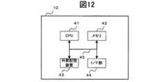
ここで、物体認識装置10のハードウェア構成について説明する。図12は、物体認識装置10の電気的な構成を示すブロック図である。 Here, the hardware configuration of the
図12に示すように、物体認識装置10は、コンピュータの主要部であって、各装置を集中的に制御するCPU(Central Processing Unit)41と、各種データを書換え可能に記憶するメモリ42と、を備える。さらに、物体認識装置10は、各種のプログラム、プログラムが生成するデータ等を格納する外部記憶装置43と、無線LANモジュールを備え、外部の装置等と通信を行う通信装置44と、を備える。これらの各装置は、バスなどの信号線45を介してCPU1と接続される。 As shown in FIG. 12, the
CPU41は、例えば、外部記憶装置43上に格納されたプログラムをメモリ42上にロードして実行することにより、各種処理を実行する。 The
外部記憶装置43は、例えばHDD(Hard Disk Drive)を備えているが、もちろん、HDDのみに限定されず、配布されたプログラムであるコンピュータソフトウェアや、データを読み取るための機構として、CD−ROM、DVD−ROM等のドライブをさらに備えてもよい。 The
以上のように構成される物体認識装置10で実行される処理について、図5に示すフロー図を用いて説明する。図5は、物体認識装置10が、撮像画像から位置情報を生成する際の処理の流れを示すフロー図である。 Processing executed by the
物体認識装置10は、条件設定部121がカーナビゲーション装置20から周囲に存在するマンホールのマンホール情報213を受信し、画像生成部122に処理の開始を要求することで以下のフローを開始する。 The
画像生成部122は、まず、車載カメラ40からフレーム画像を取得して、画像記憶領域111に蓄積する(S11)。具体的に、画像生成部122は、車載カメラ40から画像信号を取得すると、画像を構成するフレームをフレーム画像として画像記憶領域111に時系列順に格納し、条件設定部121へ条件設定要求を出力する。 First, the
条件設定部121は、条件設定要求を受け付けると、画像生成部122の実行する前処理の条件を設定する(S12)。具体的に、条件設定部121は、車速パルスセンサ30からパルス信号を、サーバから現在位置の天候・時刻等の環境情報を取得する。そして、画像記憶領域111に格納される最新のフレーム画像の輝度値およびノイズを検出して、フィルタリングの必要性や補正に関するパラメータ等の、前処理条件を設定する。 When the
次に、条件設定部121は、ハレーションが発生している領域を検出する(S13)。ここで、ハレーション領域の検出処理について、図6を参照して詳細に説明する。 Next, the
条件設定部121は、最新のフレーム画像と、連続して蓄積される過去のフレーム画像と、を画像記憶領域111から所定の数読み出して、各々の画像を任意のブロックに分割する(S131)。なお、画像記憶領域111に未だ所定の数のフレーム画像が蓄積されていない場合には、当該処理をスキップし、ステップ14へと進む。 The
次に、条件設定部121は、最新のフレーム画像と、過去の一連のフレーム画像と、の輝度値をブロックごとに比較して、ハレーション領域を特定する(S132)。具体的に、条件設定部121は、複数のフレーム画像に渡って連続して、対応するブロック内に所定の輝度値以上の画素が一定以上の割合含まれているブロックが存在するか否かを判断する。存在する場合には(S132でYES)、ステップ133へと進み、存在しない場合には(S132でNO)、ステップ14へと進む。 Next, the
一連のフレーム画像に、ハレーション領域として特定されたブロックが存在する場合には(S132でYES)、条件設定部121は、当該ブロックに対してマスク処理を実行する(S133)。具体的に、条件設定部121は、ハレーション領域として特定されたブロックに、マスク領域フラグ(例えば、「1」)を付与してラベリングする。 When a block specified as a halation area exists in a series of frame images (YES in S132), the
そして、条件設定部121は、画像生成部122へ、ステップ12で設定した前処理条件と共に画像処理要求を出力する(S134)。 Then, the
図5に戻って、画像生成部122は、前処理条件および画像処理要求を受け付けると、最新のフレーム画像について前処理を実行する(S14)。具体的に、画像生成部122は、前処理条件に基づいて、フィルタリングおよび補正等のデジタル画像処理を実行する。なお、条件設定部121によってラベリングされたマスク領域については、当該処理の対象とせずに無視する。 Returning to FIG. 5, when receiving the preprocessing condition and the image processing request, the
次に、画像生成部122は、最新のフレーム画像に俯瞰変換処理を施して、俯瞰画像を生成する(S15)。具体的には、画像生成部122は、上述の変換テーブルに基づいて、フレーム画像の各画素に対して座標変換および補正を施し、俯瞰画像を描画する。そして、画像生成部122は、生成した俯瞰画像を画像記憶領域111へと時系列順に格納し、物体認識部123へ認識処理要求を出力する。 Next, the
物体認識部123は、認識処理要求を受け付けると、所定の数の俯瞰画像を比較して、最新の俯瞰画像内におけるマンホールの有無を判断する(S16)。ここで、本実施形態にかかる物体認識部123の実行する認識処理について、以下、図3(a)、図3(b)および図7を参照して、具体的に説明する。 When the
図3(a)に示すようなフレーム画像90Aおよび90Bから、図3(b)に示すような俯瞰画像91Aおよび91Bを生成する場合について説明する。ここで、俯瞰画像91Aおよび91Bには、重畳する領域である重複領域Dと、新規に撮像され(もしくは、過去に撮像され)、俯瞰画像間のずれ量である移動領域Pと、が含まれている。 A case where overhead images 91A and 91B as shown in FIG. 3B are generated from frame images 90A and 90B as shown in FIG. 3A will be described. Here, the overhead images 91A and 91B include an overlapping region D that is an overlapping region and a moving region P that is newly captured (or captured in the past) and that is the amount of deviation between the overhead images. ing.
図7は、物体認識部123の実行する認識処理の流れの概略を示すフロー図である。 FIG. 7 is a flowchart showing an outline of the flow of recognition processing executed by the
物体認識部123はまず、俯瞰画像が認識処理を実行する際に必要な数に達しているか否かを検出する(S161)。具体的に、物体認識部123は、最新に本フローが開始されてから、画像記憶領域111に蓄積された俯瞰画像の数が予め定められた数に達しているか否かを検出する。達している場合には(S161でYES)、ステップ162へと進み、達していない場合には(S161でNO)、ステップ11へと戻って、処理を繰り返す。 First, the
次に、物体認識部123は、最新のフレーム画像および認識処理の対象となる俯瞰画像を読み出して、位置合わせ処理を実行する(S162)。具体的に、位置合わせ処理とは、重複領域Dおよび移動領域Pの特定である。重複領域Dおよび移動領域Pは、例えば、各俯瞰画像の輝度値やエッジ成分等の特徴量を抽出し、類似度が高い領域を検出することで特定できる。 Next, the
また例えば、フレームレート、単位時間あたりの移動距離から、重複領域Dおよび移動領域Pを算出することも可能である。なお、移動距離は、車速パルスセンサ30の検出信号を取得して算出すればよい。 In addition, for example, the overlapping area D and the moving area P can be calculated from the frame rate and the moving distance per unit time. The travel distance may be calculated by obtaining a detection signal from the vehicle
認識処理の対象となる俯瞰画像は、どのように選択してもよい。例えば、最新のフレーム画像から一定間隔の距離や時間等で撮像された画像を選択することが可能である。 You may select how the overhead view image used as the object of recognition processing is selected. For example, it is possible to select an image picked up from a latest frame image at a constant interval, time, or the like.
そして、物体認識部123は、俯瞰画像91Aおよび91Bを移動方向に移動領域Pの画素数だけずらして重複領域Dの差分を算出し、その輝度差が所定の閾値T1以上である領域(画素)が存在するか否かを検出する(S163)。当該領域が存在する場合には(S163でYES)、ステップ164へと進み、存在しない場合には(S163でNO)、ステップ11へと戻って、処理を繰り返す。なお、条件設定部121によってラベリングされたマスク領域については、当該処理の対象とせずに無視する。Then, the
さらに、物体認識部123は、マンホールを認識する(S164)。具体的に、物体認識部123は、ステップ163で特定された輝度差が所定の閾値T1以上である領域について、形状検出を実行する。Further, the
例えば、マンホールが円形であるという前提に則って処理を実行する場合、円形検出処理が実行される。円形検出処理とは、検出円の正当性を判断するものである。 For example, when the process is executed based on the premise that the manhole is circular, a circular detection process is executed. The circle detection process is to determine the validity of the detection circle.
例えば、物体認識部123は、ステップ163で特定された領域を抽出し、領域内の全ての画素のXY平均値を取って、その重心を定める。さらに、座標から領域の外周を判断して、外周点ごとに重心との距離を算出し、その平均値を半径と定める。そして、この半径を有する基準円を領域に重ねて、外周点と重なる比率(類似度)を算出し、円形の正当性を判断する。なお、ノイズ等によって純粋に円形でない可能性があるため、基準円はある程度の幅をもたせたものを使用する。 For example, the
なお、円形検出は上述の手法に限定されず、どのような手法を用いてもよい。例えば、領域のエッジ成分を抽出して境界線を検出し、エッジ境界線上で任意の2点を2組取得して、それらの垂直二等分線により中心点および半径を求め、円形の正当性を判断してもよい。 Note that circular detection is not limited to the above-described method, and any method may be used. For example, a boundary line is detected by extracting an edge component of a region, two sets of two arbitrary points are obtained on the edge boundary line, a center point and a radius are obtained by their perpendicular bisectors, and a circular validity May be judged.
もちろん、形状検出処理において、四角形を検出することも可能である。例えば、外周点の中から、重心との距離が最も大きい4点と、上下左右方向の最端に存在する4点と、を抽出して、基準四角形との類似度が所定の閾値以上となる組み合わせの存在の有無から、四角形の正当性を判断することが可能である。 Of course, it is also possible to detect a quadrangle in the shape detection process. For example, four points having the longest distance from the center of gravity and four points existing at the extreme ends in the vertical and horizontal directions are extracted from the outer peripheral points, and the similarity to the reference rectangle is equal to or greater than a predetermined threshold. It is possible to determine the validity of the quadrangle from the presence or absence of the combination.
また、物体認識部123は、フロー開始時に条件設定部121が取得した周囲のマンホール情報213を参照して、種別情報214cから周囲に存在するマンホールの形状を予め予測し、当該形状の検出のみを実行してもよい。また、ステップ12において、検出を要する形状を、条件設定部121が予め設定するような構成としてもよい。 Further, the
その後、物体認識部123は、位置情報生成部124へと位置情報生成要求を出力する。 Thereafter, the
図5に戻って、位置情報生成部124は、位置情報生成要求を受け付けると、俯瞰画像に含まれるマンホールの種別および自車両からマンホールまでの距離・角度を検出して、位置情報を生成する(S17)。具体的に、位置情報生成部124は、物体認識部123の認識したマンホール領域の形状やサイズ等と、フロー開始時に条件設定部121が受信したマンホール情報213の種別情報214cと、を比較して、内容が最も一致するものを検出し、そのマンホールID214aを取得する。 Returning to FIG. 5, when receiving the position information generation request, the position
さらに、位置情報生成部124は、俯瞰画像に含まれるマンホールのうち、自車両から最も近いマンホールまでの距離Sおよび角度θ3(図3(b)参照)を検出して、位置情報を生成する。Further, the position
かかる距離Sおよび角度θ2の検出には、どのような手法を用いてもよいが、例えば、俯瞰画像に対してエッジ抽出処理を実行し、その境界線上で自車両から最も近い点から自車量までの結線と、円の重心から自車両までの結線とから、距離Sおよび角度θ3を算出することが可能である。Any method may be used to detect the distance S and the angle θ2. For example, an edge extraction process is performed on the overhead view image, and the vehicle is detected from a point closest to the vehicle on the boundary line. It is possible to calculate the distance S and the angle θ3 from the connection up to the quantity and the connection from the center of gravity of the circle to the host vehicle.
そして、位置情報生成部124は、生成した位置情報を、I/F部13を介してカーナビゲーション装置20へと出力し、処理を終了する。 Then, the position
以上、物体認識装置10が、フレーム画像に含まれるマンホールの位置情報を生成する処理について説明した。上記によれば、街灯や対向車等による外乱光を利用することによって、自車両が発光手段を有していなくとも、鏡面反射の大きな金属物を検出することが可能である。 In the above, the process which the
なお、本実施形態においては検出対象となる金属物はマンホールとしているが、例えば、高速道路や橋上に存在する金属ジョイントや角の丸められた四角形の消火栓蓋等、その他の金属物に対しても応用可能である。 In the present embodiment, the metal object to be detected is a manhole, but for example, other metal objects such as metal joints present on highways and bridges and square fire hydrant lids with rounded corners. Applicable.
例えば、ジョイントは道路の端から端までを結ぶ直線状の金属物であるため、抽出されたジョイント領域の境界線の直線成分について、エッジの方向成分を投票することによって認識することができる。また、消火栓蓋の場合には、境界のエッジ成分を一般化ハフ(Hough)変換を用いて検出することが可能である。 For example, since the joint is a linear metal object that connects the ends of the road, it can be recognized by voting the edge direction component for the extracted linear component of the boundary line of the joint region. In the case of a fire hydrant lid, the edge component of the boundary can be detected using a generalized Hough transform.
また、金属物以外にも、鏡面反射成分の大きい領域であれば、例えば、水溜り等についても検出することができる。 In addition to a metal object, for example, a puddle can be detected if the region has a large specular reflection component.
なお、本実施形態においては、フレーム画像から俯瞰画像を生成しているが、これに代わって、フレーム画像から特徴量を抽出して、この特徴量の座標を変換してもよい。特徴量とは、例えば、輝度値やエッジ成分、色情報といった各画素の特徴や、コーナー点およびペイントのような図形要素、所定の領域のテクスチャおよびHLACといった統計的特長等、あらゆる画像特徴を利用することが可能である。 In this embodiment, the overhead image is generated from the frame image, but instead of this, a feature amount may be extracted from the frame image and the coordinates of the feature amount may be converted. The feature amount uses all image features such as pixel features such as luminance values, edge components, and color information, graphic elements such as corner points and paint, textures of predetermined areas, and statistical features such as HLAC. Is possible.
なお、本発明は上記の実施形態に限定されるものではなく、その要旨の範囲内で様々な変形が可能である。 In addition, this invention is not limited to said embodiment, A various deformation | transformation is possible within the range of the summary.
<変形例>
例えば、上記実施形態は、物体認識部123の実行する認識処理で使用される俯瞰画像は2枚であるが、本変形例では、認識処理に使用する俯瞰画像の数が3以上に設定されている場合について、説明する。図8は、物体認識部123の実行する位置あわせ処理の流れを説明するフロー図である。<Modification>
For example, in the above embodiment, there are two overhead images used in the recognition processing executed by the
物体認識部123は、図7のステップ161において、俯瞰画像が認識処理を実行する際に必要な数に達しているか否かを検出するが、この値は予め所定の数値が設定されているか、または、利用者によって任意で設定される。ここで例えば、この値が3以上であった場合、物体認識部123は、図8に示すような位置合わせ処理を実行する。 The
図8に示すように、俯瞰画像が予め定められた数に達している場合には(S161でYES)、物体認識部123は、各俯瞰画像を所定の組み合わせ間で位置合わせ処理を実行する(S1621)。具体的に、物体認識部123は、最新の俯瞰画像と、その他の各俯瞰画像との組み合わせの間で、それぞれ重複領域Dおよび移動領域Pを特定する。重複領域Dおよび移動領域Pの特定には、上記のどのような手段を用いても構わない。 As shown in FIG. 8, when the bird's-eye view image has reached a predetermined number (YES in S161), the
次に、物体認識部123は、ステップ1621で特定した各組み合わせの重複領域Dについて、それぞれ差分画像を生成する(S1622)。具体的に、物体認識部123は、俯瞰画像の組み合わせごとに特定された重複領域Dについて、その画素ごとに輝度値の差分を検出して、各組み合わせの差分画像を生成する。 Next, the
さらに、物体認識部123は、差分画像から統合画像を生成する(S1623)。具体的に、物体認識部123は、ステップ1622で生成した複数の差分画像について、対応する画素を比較してその最大画素値を抽出し、1枚の統合画像として集約する。 Furthermore, the
その後、物体認識部123は、当該統合画像についてステップ164の形状検出を実行する。例えば、当該統合画像のうち、所定の閾値以上の画素値を有する領域を抽出して、形状検出を実行する。 Thereafter, the
なお、本変形例において統合画像の生成は、画素の最大値を集約することで行う構成であるが、その他にも、画素値を加減算・平均化するような集約手法を用いてもよい。 In the present modification, the integrated image is generated by aggregating the maximum values of the pixels, but other aggregation methods such as addition / subtraction / averaging of pixel values may be used.
このような構成によれば、認識処理に多くの俯瞰画像を使用することによって、より細分化された撮像タイミングの画像について、認識処理を実行し、高確率でマンホールを検出することが可能である。 According to such a configuration, by using many overhead images for the recognition process, it is possible to execute the recognition process on the image with more subdivided imaging timing and detect the manhole with high probability. .
<第二の実施形態>
次に、本発明の第二の実施形態にかかる物体認識装置70について説明する。第二の実施形態にかかる物体認識装置70によれば、非金属である道路標示についても、外乱光を利用した検出が可能となる。以下、第一の実施形態と比較して、異なっている点について主に説明する。<Second Embodiment>
Next, the
図9は、物体認識システム2の、機能的な構成を示すブロック図である。 FIG. 9 is a block diagram illustrating a functional configuration of the object recognition system 2.
図示するように、物体認識システム2は、物体認識装置70と、カーナビゲーション装置80と、車速パルスセンサ30と、車載カメラ40と、を含んでいる。 As illustrated, the object recognition system 2 includes an
カーナビゲーション装置80は、例えば、GPS(全地球測位システム)や車速パルス、ジャイロなどの自立航法装置を利用して、自車両の位置の検出や、目的地への走行経路案内を実行する装置である。 The
物体認識装置70は、記憶部11と、制御部72と、I/F部13と、を有する。 The
記憶部11およびI/F部13は、第一の実施形態と同様の構成であるため、ここでは詳細な説明を省略する。 Since the
制御部72は、デジタル画像処理条件を設定する条件設定部721と、車載カメラから一定周期ごとに出力される画像を取得して俯瞰画像に変換する画像生成部722と、俯瞰画像に含まれる道路標示を検出する物体認識部723と、を有する。 The
条件設定部721は、第一の実施形態にかかる条件設定部121とほぼ同様の構成であるが、カーナビゲーション装置からマンホール情報を取得しない点において異なる。条件設定部721は、画像生成部722からの条件設定要求を受け付けると、画像記憶領域111に蓄積された最新のフレーム画像および当該画像の撮像環境に基づいて、前処理の内容の設定と、ハレーション領域の特定と、を実行する。そして、画像生成部722へと画像処理要求を出力する。 The
画像生成部722は、車載カメラ40から所定の周期毎に出力されるフレーム画像を取得して、画像記憶領域111に時系列順に蓄積し、条件設定部721へ条件設定要求を出力する。 The
また、画像生成部722は、条件設定部721からの画像処理要求を受け付けると、設定条件に基づいて最新のフレーム画像に前処理を施す。そして、フレーム画像を俯瞰画像へと変換し、物体認識部723へ認識処理要求を出力する。 In addition, upon receiving an image processing request from the
物体認識部723は、画像生成部722からの認識処理要求を受け付けると、最新の俯瞰画像中に道路標示が含まれるか否かを検出する。 When the
第一の実施形態にかかる物体認識部723は、重複領域Dにおける輝度差が閾値T1以上の領域が存在する場合に、これを金属物であると判断するが、第二の実施形態にかかる物体認識部723は、これを道路標示であると判断する。
例えば、図10に示すように、外乱光が存在する場合(時点t0)としない場合(時点t1)では、金属物ほどに反射成分を有しない道路標示(ここでは、横断歩道と路側線の一部)であっても、路面よりも大きな輝度差が存在する。そこで、物体認識部123は、このような輝度差を有する領域について、次のような処理を実行する。For example, as shown in FIG. 10, when disturbance light is present (time t0 ) and not (time t1 ), a road sign (here, a pedestrian crossing and a roadside line that does not have a reflective component as much as a metal object). Even if there is a large luminance difference than the road surface. Therefore, the
図11は、第二の実施形態にかかる物体認識部723の実行する道路標示認識処理を説明するフローチャートである。物体認識部723は、画像生成部722からの認識処理要求を受け付けると、本フローを開始する。 FIG. 11 is a flowchart for explaining road marking recognition processing executed by the
まず、物体認識部723は、俯瞰画像が認識処理を実行する際に必要な数に達しているか否かを検出する(S701)。達している場合には(S701でYES)、ステップ702へと進み、達していない場合には、処理を終了する。 First, the
次に、物体認識部723は位置合わせ処理を実行する(S702)。具体的に、物体認識部723は、フレームレート(数/s)、単位時間あたりの移動距離(m/s)、俯瞰画像の移動方向の画素数、移動方向への単位距離あたりの画素数(数/m)から、最新の俯瞰画像と過去の俯瞰画像との重複領域Dおよび移動領域Pを算出する。なお移動距離は、条件設定部721が条件設定処理時に取得する、車速パルスセンサ30の検出信号から算出すればよい。 Next, the
そして、物体認識部723は、最新の俯瞰画像と過去の俯瞰画像とを自車移動量だけずらして、重複領域Dの輝度値の差分を算出する。そして、その輝度差が所定の閾値T2以上である領域(画素)が存在するか否かを検出する(S703)。当該領域が存在する場合には(S703でYES)、ステップ704へと進み、存在しない場合には(S703でNO)、処理を終了する。Then, the
ここで、所定の閾値T2は、外乱交を反射する道路標示を検出するために設けられる値であるため、第一の実施形態にかかる鏡面反射成分の大きな金属物を検出するために設けられる閾値T1よりも、小さな値であることが望ましい。Here, the predetermined threshold value T2 are, because it is a value that is provided to detect a road sign reflects disturbance exchange is provided to detect a large metal product of the specular reflection component according to a first embodiment than the threshold value T1, it is desirable that a small value.
輝度差が所定の閾値T2以上である領域が存在するか場合(S703でYES)、物体認識部723は、加算画像を生成する(S704)。具体的に、物体認識部723は、重複領域Dを加算して、よりコントラスト強度を増した加算画像を生成する。なお、加算合成は、対応する画素のうち最大値を有効とする演算を実行してもよい。If either the brightness difference is there is a region a predetermined thresholdT 2 or more (YES in S703), the
次に、物体認識部723は、道路標示の有無を検出する(S705)。具体的に、物体認識部723は、加算画像上のステップ703で特定された輝度差が所定の閾値T2以上である領域について、形状検出処理を実行する。Next, the
なお、道路標示の種別ごとに検出される形状が異なるため、カーナビゲーション装置80の地図データに道路標示とその種別(形状)に関する情報を予め格納し、物体認識部723は、カーナビゲーション装置80から周辺に存在する道路標示に関する情報を取得して、検出対象となる形状を決定してもよい。 Since the detected shape is different for each type of road marking, information relating to the road marking and its type (shape) is stored in advance in the map data of the
また、形状検出の代わりに、特徴量によるテンプレートマッチングによって、道路標示を認識してもよい。例えば、加算画像の特徴量(縦方向および横方向の累積輝度値やエッジ成分等)と、基準となる道路標示の特徴量を記憶するテンプレートとのマッチングによって、道路標示の種別を特定することが可能である。 Moreover, you may recognize a road marking by the template matching by a feature-value instead of shape detection. For example, the type of road marking can be specified by matching the feature amount of the added image (cumulative luminance values and edge components in the vertical and horizontal directions) with a template that stores the feature amount of the reference road marking. Is possible.
さらに、検出した道路標示について、自車両との相対位置を算出し、カーナビゲーション装置80へと出力してもよい。カーナビゲーション装置80は、これに協調して自車両の位置を補正する構成とすることも可能である。 Further, the relative position of the detected road marking with the host vehicle may be calculated and output to the
以上のような構成により、本実施形態にかかる物体認識装置70は、外乱光を利用して、撮像画像内における道路標示を検出することができる。また、加算画像を生成することによって、道路標示にかすれ等が生じている場合でも、精度よく道路標示を認識することが可能である。 With the configuration as described above, the
10・70・・・物体認識装置、20・80・・・カーナビゲーション装置、30・・・車速パルスセンサ、40・・・車載カメラ、11・・・記憶部、111・・・画像記憶領域、112・・・変換テーブル記憶領域、12、72・・・制御部、121、721・・・条件設定部、122、722・・・画像生成部、123、723・・・物体認識部、124・・・位置情報生成部、13・・・インターフェース部。DESCRIPTION OF SYMBOLS 10.70 ... Object recognition apparatus, 20.80 ... Car navigation apparatus, 30 ... Vehicle speed pulse sensor, 40 ... In-vehicle camera, 11 ... Memory | storage part, 111 ... Image storage area, 112 ... conversion table storage area, 12, 72 ... control unit, 121, 721 ... condition setting unit, 122, 722 ... image generation unit, 123, 723 ... object recognition unit, 124 ..Position information generation unit, 13... Interface unit.
Claims (9)
Translated fromJapanese前記撮像手段が異なる時点で撮像した画像を、垂直方向から見下ろす合成画像にそれぞれ変換する画像生成手段と、
複数の前記合成画像を比較して、対応する領域を検出する検出手段と、
前記対応する領域のうち輝度値の差異が大きい領域に対して円形検出処理を行い、円形のマンホールを認識する認識手段と、を備える
ことを特徴とする物体認識装置。Imaging means mounted on a moving body;
Image generating means for converting images taken at different times by the imaging means into composite images looking down from the vertical direction;
Detecting means for comparing a plurality of the composite images and detecting corresponding regions;
An object recognition apparatus comprising: arecognition unit that performs circular detection processing on a region having a large difference in luminance value among the corresponding regions, and recognizes a circular manhole .
前記撮像手段が異なる時点で撮像した画像を、垂直方向から見下ろす合成画像にそれぞれ変換する画像生成手段と、
複数の前記合成画像を比較して、対応する領域を検出する検出手段と、
前記対応する領域のうち輝度値の差異が大きい領域に対して四角形検出処理を行い、四角形のマンホールを認識する認識手段と、を備える
ことを特徴とする物体認識装置。Imaging means mounted on a moving body;
Image generating means for converting images taken at different times by the imaging means into composite images looking down from the vertical direction;
Detecting means for comparing a plurality of the composite images and detecting corresponding regions;
An object recognition apparatus comprising: a recognition unit configuredto perform a quadrangle detection process on a region having a large difference in luminance value among the corresponding regions to recognize a quadrangle manhole .
マンホールごとに、少なくともその位置と、形状と、を特定する情報を有するマンホール情報から、前記認識されたマンホールを識別し、該マンホールの位置情報を生成する位置情報生成手段を、さらに有することFor each manhole, there is further provided position information generating means for identifying the recognized manhole from the manhole information having information for specifying at least its position and shape and generating the position information of the manhole.
を特徴とする物体認識装置。An object recognition device.
前記検出手段は、前記複数の合成画像間における前記移動体の移動量から、前記領域を検出すること
を特徴とする物体認識装置。The object recognition device according toany one of claims1 to 3 ,
The object recognition apparatus, wherein the detection unit detects the region from a moving amount of the moving body between the plurality of synthesized images.
車速、加速度、角速度のうち、少なくとも1つを検出するセンサを備え、
前記センサのうち、少なくとも1つを用いて前記移動体の移動量を算出する
ことを特徴とする物体認識装置。The object recognition device according to claim4 ,
A sensor that detects at least one of vehicle speed, acceleration, and angular velocity;
The amount of movement of the movable body is calculated using at least one of the sensors.
前記検出手段は、
前記複数の合成画像に含まれる特徴点を検出し、
前記特徴点の移動量から、前記移動体の移動量を算出する
ことを特徴とする物体認識装置。The object recognition device according to claim4 ,
The detection means includes
Detecting feature points included in the plurality of composite images;
An object recognition apparatus, wherein the movement amount of the moving body is calculated from the movement amount of the feature point.
前記認識手段は、
前記対応する領域を加算して加算画像を生成し、
前記加算画像から、路面に存在する物体を認識する
ことを特徴とする物体認識装置。The object recognition device according to any one of claims 1 to6 ,
The recognition means is
Adding the corresponding regions to generate an added image;
An object recognition apparatus for recognizing an object existing on a road surface from the added image.
複数の前記合成画像を比較して、対応する領域を検出するステップと、
前記対応する領域のうち輝度値の差異が大きい領域に対して形状検出処理を行い、円形及び四角形のマンホールを認識するステップと、を有する
ことを特徴とする物体認識方法。Converting images captured at different times into composite images looking down from the vertical direction,
Comparing a plurality of the composite images to detect corresponding regions;
An object recognition methodcomprising: performing shape detection processing on a region having a large difference in luminance value among the corresponding regions, and recognizing circular and square manholes .
マンホールごとに、少なくともその位置と、形状と、を特定する情報を有するマンホール情報から、前記認識されたマンホールを識別し、該マンホールの位置情報を生成するステップと、をさらに有するFurther comprising the step of identifying each recognized manhole from the manhole information having information specifying at least its position and shape for each manhole, and generating position information of the manhole.
ことを特徴とする物体認識方法。An object recognition method characterized by the above.
Priority Applications (4)
| Application Number | Priority Date | Filing Date | Title |
|---|---|---|---|
| JP2008115681AJP4871909B2 (en) | 2008-04-25 | 2008-04-25 | Object recognition apparatus and object recognition method |
| PCT/JP2009/058161WO2009131210A1 (en) | 2008-04-25 | 2009-04-24 | Object recognizing device and object recognizing method |
| EP09734385.9AEP2282295B1 (en) | 2008-04-25 | 2009-04-24 | Object recognizing device and object recognizing method |
| US12/918,042US8818026B2 (en) | 2008-04-25 | 2009-04-24 | Object recognition device and object recognition method |
Applications Claiming Priority (1)
| Application Number | Priority Date | Filing Date | Title |
|---|---|---|---|
| JP2008115681AJP4871909B2 (en) | 2008-04-25 | 2008-04-25 | Object recognition apparatus and object recognition method |
Publications (2)
| Publication Number | Publication Date |
|---|---|
| JP2009266003A JP2009266003A (en) | 2009-11-12 |
| JP4871909B2true JP4871909B2 (en) | 2012-02-08 |
Family
ID=41216936
Family Applications (1)
| Application Number | Title | Priority Date | Filing Date |
|---|---|---|---|
| JP2008115681AExpired - Fee RelatedJP4871909B2 (en) | 2008-04-25 | 2008-04-25 | Object recognition apparatus and object recognition method |
Country Status (4)
| Country | Link |
|---|---|
| US (1) | US8818026B2 (en) |
| EP (1) | EP2282295B1 (en) |
| JP (1) | JP4871909B2 (en) |
| WO (1) | WO2009131210A1 (en) |
Families Citing this family (52)
| Publication number | Priority date | Publication date | Assignee | Title |
|---|---|---|---|---|
| JP5569042B2 (en)* | 2010-03-02 | 2014-08-13 | 株式会社リコー | Image processing apparatus, imaging apparatus, and image processing method |
| US8625902B2 (en)* | 2010-07-30 | 2014-01-07 | Qualcomm Incorporated | Object recognition using incremental feature extraction |
| JP5830876B2 (en)* | 2011-02-18 | 2015-12-09 | 富士通株式会社 | Distance calculation program, distance calculation method, and distance calculation device |
| EP2769376A4 (en) | 2011-09-23 | 2015-07-22 | Mri Inc | SYSTEM AND METHOD FOR ENVIRONMENTALLY ADAPTING DISPLAY CHARACTERISTICS |
| CN103164851B (en)* | 2011-12-09 | 2016-04-20 | 株式会社理光 | Lane segmentation object detecting method and device |
| DE102012209316A1 (en)* | 2012-06-01 | 2013-12-05 | Robert Bosch Gmbh | Method and device for processing sensor data of a stereo sensor system |
| JP6051608B2 (en)* | 2012-06-19 | 2016-12-27 | 市光工業株式会社 | Vehicle surrounding object detection device |
| DE102012012501B4 (en)* | 2012-06-21 | 2019-10-24 | Volkswagen Aktiengesellschaft | Camera system for a motor vehicle |
| JP2014089630A (en)* | 2012-10-31 | 2014-05-15 | Nippon Lock:Kk | Vehicle alarm device controller |
| US9488483B2 (en) | 2013-05-17 | 2016-11-08 | Honda Motor Co., Ltd. | Localization using road markings |
| US9335766B1 (en) | 2013-12-06 | 2016-05-10 | Google Inc. | Static obstacle detection |
| WO2015106114A1 (en) | 2014-01-13 | 2015-07-16 | T1visions, Inc. | Display capable of object recognition |
| JP6313063B2 (en)* | 2014-02-17 | 2018-04-18 | 日立オートモティブシステムズ株式会社 | In-vehicle recognition device |
| EP2918974B1 (en)* | 2014-03-11 | 2019-01-16 | Volvo Car Corporation | Method and system for determining a position of a vehicle |
| JP6223256B2 (en)* | 2014-03-28 | 2017-11-01 | 株式会社パスコ | Manhole cover management device, manhole cover management method and program |
| JP2015191572A (en)* | 2014-03-28 | 2015-11-02 | 株式会社パスコ | Manhole detection device, manhole detection method and program |
| JP6348020B2 (en)* | 2014-08-29 | 2018-06-27 | 株式会社日立製作所 | Image processing apparatus, image processing method, and inspection method using the same |
| JP6361382B2 (en)* | 2014-08-29 | 2018-07-25 | アイシン精機株式会社 | Vehicle control device |
| JP6234349B2 (en) | 2014-09-16 | 2017-11-22 | 株式会社東芝 | Mobile object position estimation device, mobile object position estimation method, and mobile object position estimation program |
| US9990550B2 (en) | 2014-09-19 | 2018-06-05 | Bendix Commercial Vehicle Systems Llc | Wide baseline object detection stereo system |
| JP6619927B2 (en) | 2014-10-24 | 2019-12-11 | 株式会社日立製作所 | Calibration device |
| CN112902975B (en)* | 2015-02-10 | 2024-04-30 | 御眼视觉技术有限公司 | Autonomous vehicle navigation method, readable device, server, vehicle and system |
| US10607520B2 (en) | 2015-05-14 | 2020-03-31 | Manufacturing Resources International, Inc. | Method for environmental adaptation of display characteristics based on location |
| US10593255B2 (en)* | 2015-05-14 | 2020-03-17 | Manufacturing Resources International, Inc. | Electronic display with environmental adaptation of display characteristics based on location |
| US9924583B2 (en) | 2015-05-14 | 2018-03-20 | Mnaufacturing Resources International, Inc. | Display brightness control based on location data |
| EP3136291A1 (en)* | 2015-08-31 | 2017-03-01 | Continental Automotive GmbH | Method and device for detecting objects in the dark by means of a vehicular camera and a vehicle lighting system |
| DE102015219496A1 (en)* | 2015-10-08 | 2017-04-13 | Robert Bosch Gmbh | Method for determining the functionality of a driver assistance system of a vehicle, device, driver assistance system, motor vehicle |
| KR102522611B1 (en)* | 2015-12-10 | 2023-04-19 | 현대모비스 주식회사 | System for correcting the signal of the ultrasonic sensor according to the weather conditions and method thereof |
| CN105719284B (en) | 2016-01-18 | 2018-11-06 | 腾讯科技(深圳)有限公司 | A kind of data processing method, device and terminal |
| DE102016204319A1 (en)* | 2016-03-16 | 2017-09-21 | Conti Temic Microelectronic Gmbh | Method and apparatus for a vehicle for detecting ground symbols |
| US10576892B2 (en)* | 2016-03-24 | 2020-03-03 | Ford Global Technologies, Llc | System and method for generating a hybrid camera view in a vehicle |
| US9866927B2 (en) | 2016-04-22 | 2018-01-09 | Microsoft Technology Licensing, Llc | Identifying entities based on sensor data |
| JP2017199130A (en)* | 2016-04-26 | 2017-11-02 | 株式会社デンソー | Image processing apparatus, image processing method, and program |
| US10670418B2 (en)* | 2016-05-04 | 2020-06-02 | International Business Machines Corporation | Video based route recognition |
| JP6727032B2 (en)* | 2016-05-26 | 2020-07-22 | 三菱電機株式会社 | Mobile terminal, self-position estimation system using the same, server and self-position estimation method |
| EP3263405B1 (en)* | 2016-06-27 | 2019-08-07 | Volvo Car Corporation | Around view monitoring system and method for vehicles |
| JP6622664B2 (en)* | 2016-07-12 | 2019-12-18 | 株式会社Soken | Self-vehicle position specifying device and self-vehicle position specifying method |
| GB2556328A (en)* | 2016-09-05 | 2018-05-30 | Xihelm Ltd | Street asset mapping |
| US10710579B2 (en)* | 2017-06-01 | 2020-07-14 | Waymo Llc | Collision prediction system |
| US10579067B2 (en)* | 2017-07-20 | 2020-03-03 | Huawei Technologies Co., Ltd. | Method and system for vehicle localization |
| US10578658B2 (en) | 2018-05-07 | 2020-03-03 | Manufacturing Resources International, Inc. | System and method for measuring power consumption of an electronic display assembly |
| WO2019241546A1 (en) | 2018-06-14 | 2019-12-19 | Manufacturing Resources International, Inc. | System and method for detecting gas recirculation or airway occlusion |
| JP7223629B2 (en)* | 2019-05-13 | 2023-02-16 | 日立Astemo株式会社 | In-vehicle system, external recognition sensor, electronic control unit |
| US11834082B2 (en)* | 2019-09-18 | 2023-12-05 | Progress Rail Services Corporation | Rail buckle detection and risk prediction |
| US11526044B2 (en) | 2020-03-27 | 2022-12-13 | Manufacturing Resources International, Inc. | Display unit with orientation based operation |
| JP7347302B2 (en)* | 2020-03-31 | 2023-09-20 | 株式会社デンソー | remote parking system |
| US11472402B2 (en) | 2020-04-23 | 2022-10-18 | Deere & Company | Work tool collision avoidance method and system for a work machine |
| JP7138157B2 (en)* | 2020-12-25 | 2022-09-15 | エヌ・ティ・ティ・コムウェア株式会社 | OBJECT DETECTION DEVICE, OBJECT DETECTION METHOD, AND PROGRAM |
| JP2022132882A (en)* | 2021-03-01 | 2022-09-13 | キヤノン株式会社 | Navigation system, navigation method and program |
| US12105370B2 (en) | 2021-03-15 | 2024-10-01 | Manufacturing Resources International, Inc. | Fan control for electronic display assemblies |
| AU2022238796B2 (en) | 2021-03-15 | 2024-09-19 | Manufacturing Resources International, Inc. | Fan control for electronic display assemblies |
| US12027132B1 (en) | 2023-06-27 | 2024-07-02 | Manufacturing Resources International, Inc. | Display units with automated power governing |
Family Cites Families (19)
| Publication number | Priority date | Publication date | Assignee | Title |
|---|---|---|---|---|
| JPH04171586A (en)* | 1990-11-06 | 1992-06-18 | Nippon Telegr & Teleph Corp <Ntt> | Pattern retrieving method |
| JPH07152434A (en) | 1993-12-01 | 1995-06-16 | Fuji Heavy Ind Ltd | Own position detecting method for autonomously traveling work wagon |
| JP3138381B2 (en) | 1994-01-20 | 2001-02-26 | 株式会社日立製作所 | Monitoring device |
| JPH11203446A (en)* | 1998-01-12 | 1999-07-30 | Toyota Motor Corp | Photographing object recognizing device |
| US6266442B1 (en) | 1998-10-23 | 2001-07-24 | Facet Technology Corp. | Method and apparatus for identifying objects depicted in a videostream |
| JP3584194B2 (en)* | 2000-02-22 | 2004-11-04 | 株式会社ホンダエレシス | White line detection method and white line detection device |
| WO2003023557A2 (en)* | 2001-09-06 | 2003-03-20 | Wtd Technologies, Inc. | Accident evidence recording method |
| JP4956915B2 (en) | 2005-05-20 | 2012-06-20 | 日産自動車株式会社 | Video display device and video display method |
| JP4365350B2 (en)* | 2005-06-27 | 2009-11-18 | 本田技研工業株式会社 | Vehicle and lane recognition device |
| JP4820712B2 (en)* | 2005-08-05 | 2011-11-24 | アイシン・エィ・ダブリュ株式会社 | Road marking recognition system |
| JP2007235642A (en)* | 2006-03-02 | 2007-09-13 | Hitachi Ltd | Obstacle detection system |
| JP4295298B2 (en)* | 2006-08-07 | 2009-07-15 | 株式会社日立製作所 | Vehicle driving support control device |
| JP4309920B2 (en)* | 2007-01-29 | 2009-08-05 | 株式会社東芝 | Car navigation system, road marking identification program, and road marking identification method |
| US7714704B1 (en)* | 2007-08-24 | 2010-05-11 | Joshua Mellen | Removable video safety system for a moving vehicle |
| JP4521642B2 (en)* | 2008-02-13 | 2010-08-11 | 本田技研工業株式会社 | Vehicle periphery monitoring device, vehicle, vehicle periphery monitoring program |
| JP2010016805A (en)* | 2008-06-04 | 2010-01-21 | Sanyo Electric Co Ltd | Image processing apparatus, driving support system, and image processing method |
| KR101067424B1 (en)* | 2008-07-28 | 2011-09-27 | 삼성전자주식회사 | Traffic information display method and device using a widget of a mobile terminal |
| US8699755B2 (en)* | 2009-02-20 | 2014-04-15 | Navteq B.V. | Determining travel path features based on retroreflectivity |
| US9047672B2 (en)* | 2009-12-14 | 2015-06-02 | Nec Corporation | Image generation apparatus, image generation method and image generation program |
- 2008
- 2008-04-25JPJP2008115681Apatent/JP4871909B2/ennot_activeExpired - Fee Related
- 2009
- 2009-04-24EPEP09734385.9Apatent/EP2282295B1/ennot_activeNot-in-force
- 2009-04-24USUS12/918,042patent/US8818026B2/enactiveActive
- 2009-04-24WOPCT/JP2009/058161patent/WO2009131210A1/enactiveApplication Filing
Also Published As
| Publication number | Publication date |
|---|---|
| JP2009266003A (en) | 2009-11-12 |
| US20120269382A1 (en) | 2012-10-25 |
| WO2009131210A1 (en) | 2009-10-29 |
| EP2282295A4 (en) | 2013-10-30 |
| US8818026B2 (en) | 2014-08-26 |
| EP2282295B1 (en) | 2014-12-31 |
| EP2282295A1 (en) | 2011-02-09 |
Similar Documents
| Publication | Publication Date | Title |
|---|---|---|
| JP4871909B2 (en) | Object recognition apparatus and object recognition method | |
| CN113160594B (en) | Change point detection device and map information publishing system | |
| JP6626410B2 (en) | Vehicle position specifying device and vehicle position specifying method | |
| US8175331B2 (en) | Vehicle surroundings monitoring apparatus, method, and program | |
| JP4557288B2 (en) | Image recognition device, image recognition method, position specifying device using the same, vehicle control device, and navigation device | |
| CN106647776B (en) | Method and device for judging lane changing trend of vehicle and computer storage medium | |
| US9652980B2 (en) | Enhanced clear path detection in the presence of traffic infrastructure indicator | |
| JP4930046B2 (en) | Road surface discrimination method and road surface discrimination device | |
| TWI534764B (en) | Apparatus and method for vehicle positioning | |
| JP2019099138A (en) | Lane-keep auxiliary method and device | |
| JP4902575B2 (en) | Road sign recognition device and road sign recognition method | |
| WO2015087502A1 (en) | Vehicle self-location device | |
| JP2007235642A (en) | Obstacle detection system | |
| CN110388928B (en) | Navigation system and updating method and device of navigation map | |
| JP6278791B2 (en) | Vehicle position detection device, vehicle position detection method, vehicle position detection computer program, and vehicle position detection system | |
| WO2015177864A1 (en) | Traffic-light recognition device and traffic-light recognition method | |
| WO2020004231A1 (en) | Lane estimation device, method, and program | |
| JP6278790B2 (en) | Vehicle position detection device, vehicle position detection method, vehicle position detection computer program, and vehicle position detection system | |
| JP2019146012A (en) | Imaging apparatus | |
| JP5062091B2 (en) | Moving object identification device, computer program, and optical axis direction specifying method | |
| JP2011103058A (en) | Erroneous recognition prevention device | |
| JP2002190023A (en) | Patent application title: VEHICLE TYPE DISCRIMINATION DEVICE, VEHICLE TYPE DISCRIMINATION METHOD, AND STORAGE MEDIUM CONTAINING COMPUTER-READABLE PROGRAM FOR PERFORMING VEHICLE TYPE DISCRIMINATION METHOD | |
| JP2018073049A (en) | Image recognition device, image recognition system, and image recognition method | |
| JP2007018451A (en) | Road marking line detection device | |
| WO2025158936A1 (en) | Environment recognition device |
Legal Events
| Date | Code | Title | Description |
|---|---|---|---|
| A711 | Notification of change in applicant | Free format text:JAPANESE INTERMEDIATE CODE: A712 Effective date:20100119 | |
| A621 | Written request for application examination | Free format text:JAPANESE INTERMEDIATE CODE: A621 Effective date:20100319 | |
| A521 | Request for written amendment filed | Free format text:JAPANESE INTERMEDIATE CODE: A523 Effective date:20110829 | |
| TRDD | Decision of grant or rejection written | ||
| A01 | Written decision to grant a patent or to grant a registration (utility model) | Free format text:JAPANESE INTERMEDIATE CODE: A01 Effective date:20111025 | |
| A01 | Written decision to grant a patent or to grant a registration (utility model) | Free format text:JAPANESE INTERMEDIATE CODE: A01 | |
| A61 | First payment of annual fees (during grant procedure) | Free format text:JAPANESE INTERMEDIATE CODE: A61 Effective date:20111121 | |
| R150 | Certificate of patent or registration of utility model | Ref document number:4871909 Country of ref document:JP Free format text:JAPANESE INTERMEDIATE CODE: R150 Free format text:JAPANESE INTERMEDIATE CODE: R150 | |
| FPAY | Renewal fee payment (event date is renewal date of database) | Free format text:PAYMENT UNTIL: 20141125 Year of fee payment:3 | |
| S533 | Written request for registration of change of name | Free format text:JAPANESE INTERMEDIATE CODE: R313533 | |
| R350 | Written notification of registration of transfer | Free format text:JAPANESE INTERMEDIATE CODE: R350 | |
| LAPS | Cancellation because of no payment of annual fees |