JP4869734B2 - Multi-photon excitation scanning laser microscope - Google Patents
Multi-photon excitation scanning laser microscopeDownload PDFInfo
- Publication number
- JP4869734B2 JP4869734B2JP2006046768AJP2006046768AJP4869734B2JP 4869734 B2JP4869734 B2JP 4869734B2JP 2006046768 AJP2006046768 AJP 2006046768AJP 2006046768 AJP2006046768 AJP 2006046768AJP 4869734 B2JP4869734 B2JP 4869734B2
- Authority
- JP
- Japan
- Prior art keywords
- pulse laser
- ultrashort pulse
- wavelength
- optical system
- laser beam
- Prior art date
- Legal status (The legal status is an assumption and is not a legal conclusion. Google has not performed a legal analysis and makes no representation as to the accuracy of the status listed.)
- Expired - Fee Related
Links
- 230000005284excitationEffects0.000titleclaimsdescription64
- 230000003287optical effectEffects0.000claimsdescription136
- 239000006185dispersionSubstances0.000claimsdescription70
- 239000013307optical fiberSubstances0.000claimsdescription40
- 238000001228spectrumMethods0.000claimsdescription18
- 238000001514detection methodMethods0.000claimsdescription8
- 238000007493shaping processMethods0.000description16
- 230000000694effectsEffects0.000description8
- 210000001747pupilAnatomy0.000description8
- 238000010586diagramMethods0.000description7
- 230000003595spectral effectEffects0.000description6
- 230000000638stimulationEffects0.000description6
- 238000002073fluorescence micrographMethods0.000description5
- 238000003384imaging methodMethods0.000description5
- 230000001678irradiating effectEffects0.000description4
- 238000000034methodMethods0.000description4
- 230000008878couplingEffects0.000description3
- 238000010168coupling processMethods0.000description3
- 238000005859coupling reactionMethods0.000description3
- 239000000835fiberSubstances0.000description3
- 238000005286illuminationMethods0.000description3
- 239000000463materialSubstances0.000description3
- 230000004048modificationEffects0.000description3
- 238000012986modificationMethods0.000description3
- 230000001902propagating effectEffects0.000description3
- 239000000126substanceSubstances0.000description3
- 239000007850fluorescent dyeSubstances0.000description2
- 230000009022nonlinear effectEffects0.000description2
- 230000004075alterationEffects0.000description1
- 230000008901benefitEffects0.000description1
- BJQHLKABXJIVAM-UHFFFAOYSA-Nbis(2-ethylhexyl) phthalateChemical compoundCCCCC(CC)COC(=O)C1=CC=CC=C1C(=O)OCC(CC)CCCCBJQHLKABXJIVAM-UHFFFAOYSA-N0.000description1
- 230000008859changeEffects0.000description1
- 239000000284extractSubstances0.000description1
- 238000005259measurementMethods0.000description1
- 239000004038photonic crystalSubstances0.000description1
- 230000008719thickeningEffects0.000description1
Images


Classifications
- G—PHYSICS
- G01—MEASURING; TESTING
- G01J—MEASUREMENT OF INTENSITY, VELOCITY, SPECTRAL CONTENT, POLARISATION, PHASE OR PULSE CHARACTERISTICS OF INFRARED, VISIBLE OR ULTRAVIOLET LIGHT; COLORIMETRY; RADIATION PYROMETRY
- G01J3/00—Spectrometry; Spectrophotometry; Monochromators; Measuring colours
- G01J3/28—Investigating the spectrum
- G01J3/44—Raman spectrometry; Scattering spectrometry ; Fluorescence spectrometry
- G01J3/4406—Fluorescence spectrometry
- G—PHYSICS
- G01—MEASURING; TESTING
- G01J—MEASUREMENT OF INTENSITY, VELOCITY, SPECTRAL CONTENT, POLARISATION, PHASE OR PULSE CHARACTERISTICS OF INFRARED, VISIBLE OR ULTRAVIOLET LIGHT; COLORIMETRY; RADIATION PYROMETRY
- G01J3/00—Spectrometry; Spectrophotometry; Monochromators; Measuring colours
- G01J3/02—Details
- G01J3/10—Arrangements of light sources specially adapted for spectrometry or colorimetry
- G—PHYSICS
- G01—MEASURING; TESTING
- G01N—INVESTIGATING OR ANALYSING MATERIALS BY DETERMINING THEIR CHEMICAL OR PHYSICAL PROPERTIES
- G01N21/00—Investigating or analysing materials by the use of optical means, i.e. using sub-millimetre waves, infrared, visible or ultraviolet light
- G01N21/62—Systems in which the material investigated is excited whereby it emits light or causes a change in wavelength of the incident light
- G01N21/63—Systems in which the material investigated is excited whereby it emits light or causes a change in wavelength of the incident light optically excited
- G01N21/64—Fluorescence; Phosphorescence
- G01N21/645—Specially adapted constructive features of fluorimeters
- G01N21/6456—Spatial resolved fluorescence measurements; Imaging
- G01N21/6458—Fluorescence microscopy
- G—PHYSICS
- G02—OPTICS
- G02B—OPTICAL ELEMENTS, SYSTEMS OR APPARATUS
- G02B21/00—Microscopes
- G02B21/0004—Microscopes specially adapted for specific applications
- G02B21/002—Scanning microscopes
- G02B21/0024—Confocal scanning microscopes (CSOMs) or confocal "macroscopes"; Accessories which are not restricted to use with CSOMs, e.g. sample holders
- G02B21/0052—Optical details of the image generation
- G02B21/0076—Optical details of the image generation arrangements using fluorescence or luminescence
- G—PHYSICS
- G02—OPTICS
- G02B—OPTICAL ELEMENTS, SYSTEMS OR APPARATUS
- G02B21/00—Microscopes
- G02B21/0004—Microscopes specially adapted for specific applications
- G02B21/002—Scanning microscopes
- G02B21/0024—Confocal scanning microscopes (CSOMs) or confocal "macroscopes"; Accessories which are not restricted to use with CSOMs, e.g. sample holders
- G02B21/008—Details of detection or image processing, including general computer control
- G02B21/0084—Details of detection or image processing, including general computer control time-scale detection, e.g. strobed, ultra-fast, heterodyne detection
- G—PHYSICS
- G01—MEASURING; TESTING
- G01N—INVESTIGATING OR ANALYSING MATERIALS BY DETERMINING THEIR CHEMICAL OR PHYSICAL PROPERTIES
- G01N2201/00—Features of devices classified in G01N21/00
- G01N2201/06—Illumination; Optics
- G01N2201/061—Sources
- G01N2201/06113—Coherent sources; lasers
- G—PHYSICS
- G01—MEASURING; TESTING
- G01N—INVESTIGATING OR ANALYSING MATERIALS BY DETERMINING THEIR CHEMICAL OR PHYSICAL PROPERTIES
- G01N2201/00—Features of devices classified in G01N21/00
- G01N2201/08—Optical fibres; light guides
Landscapes
- Physics & Mathematics (AREA)
- Spectroscopy & Molecular Physics (AREA)
- General Physics & Mathematics (AREA)
- Chemical & Material Sciences (AREA)
- Analytical Chemistry (AREA)
- Health & Medical Sciences (AREA)
- Optics & Photonics (AREA)
- General Engineering & Computer Science (AREA)
- Engineering & Computer Science (AREA)
- Nuclear Medicine, Radiotherapy & Molecular Imaging (AREA)
- Life Sciences & Earth Sciences (AREA)
- Biochemistry (AREA)
- General Health & Medical Sciences (AREA)
- Immunology (AREA)
- Pathology (AREA)
- Computer Vision & Pattern Recognition (AREA)
- Microscoopes, Condenser (AREA)
- Investigating, Analyzing Materials By Fluorescence Or Luminescence (AREA)
Description
Translated fromJapaneseこの発明は、多光子励起走査型レーザ顕微鏡に関するものである。 The present invention relates to a multiphoton excitation scanning laser microscope.
従来、生体等の標本にその表面から超短パルスレーザ光を照射して、標本の表面下の比較的深い位置から発せられる多光子蛍光を検出することにより、細胞等の機能を観察する装置として、多光子励起型の測定装置が知られている(例えば、特許文献1参照。)。
この多光子励起型測定装置において、波長の異なる複数の超短パルスレーザ光を照射して、異なる多光子蛍光を観察する場合には、レーザ光源として、複数の波長の超短パルスレーザ光を出射可能なものを採用、または、単一波長の超短パルスレーザ光源を複数台使用する必要があった。Conventionally, as a device for observing the function of cells and the like by irradiating a specimen such as a living body with ultrashort pulse laser light from its surface and detecting multiphoton fluorescence emitted from a relatively deep position below the surface of the specimen A multiphoton excitation type measuring apparatus is known (for example, see Patent Document 1).
In this multiphoton excitation type measurement device, when irradiating multiple ultrashort pulse laser beams with different wavelengths and observing different multiphoton fluorescence, the laser light source emits ultrashort pulse laser beams with multiple wavelengths. It was necessary to adopt a possible one or to use a plurality of single-wavelength ultrashort pulse laser light sources.
一方、共焦点走査型蛍光顕微鏡において、フェムト秒オーダーの超短パルスレーザ光を、フォトニックバンドギャップ材のような微細構造光学要素に入射させることによってスペクトル拡散させ、広い波長帯域を有するレーザ光を出射させるとともに、音響光学フィルタ(AOTF)やプリズム、あるいはグレーティングを用いて波長範囲を選択する装置が知られている(例えば、特許文献2参照。)。
しかしながら、特許文献1の多光子励起型測定装置においては、複数波長の超短パルスレーザ光を出射可能なレーザ光源が大型のものとなり、装置全体が大型化するとともに、コストが高くなるという問題がある。
また、特許文献2は、共焦点走査型蛍光顕微鏡に関する技術が開示されているのみであり、これを多光子励起型蛍光顕微鏡に適用することについては何ら開示されていない。However, in the multiphoton excitation type measuring apparatus of
本発明は上述した事情に鑑みてなされたものであって、複数波長の超短パルスレーザ光を標本に照射して、複数波長の多光子蛍光を観察することができる、小型で、しかも、コストの低い多光子励起走査型レーザ顕微鏡を提供することを目的としている。 The present invention has been made in view of the above-described circumstances, and is small in size and capable of observing multi-photon fluorescence of a plurality of wavelengths by irradiating a sample with an ultrashort pulse laser beam of a plurality of wavelengths. An object of the present invention is to provide a multiphoton excitation scanning laser microscope having a low A.
上記目的を達成するために、本発明は、以下の手段を提供する。
本発明は、単一波長の超短パルスレーザ光を出射するレーザ光源と、該レーザ光源からの超短パルスレーザ光を入射させ、超短パルスレーザ光のスペクトルを拡散させる光ファイバと、該光ファイバから出射されたスペクトル拡散された超短パルスレーザ光を走査するレーザ走査部と、該レーザ走査部により走査された超短パルスレーザ光を標本に集光させる対物光学系と、標本における超短パルスレーザ光の集光位置から発せられた多光子蛍光を検出する光検出器と、群速度分散を補償する分散補償光学系とを備える多光子励起走査型レーザ顕微鏡を提供する。In order to achieve the above object, the present invention provides the following means.
The present invention includes a laser light source that emits a single-wavelength ultrashort pulse laser beam, an optical fiber that causes the ultrashort pulse laser beam from the laser light source to enter and diffuses the spectrum of the ultrashort pulse laser beam, and the light A laser scanning unit that scans the spectrum-spread ultrashort pulse laser beam emitted from the fiber; an objective optical system that focuses the ultrashort pulse laser beam scanned by the laser scanning unit on the sample; Provided is a multiphoton excitation scanning laser microscope comprising a photodetector for detecting multiphoton fluorescence emitted from a focused position of pulsed laser light and a dispersion compensation optical system for compensating for group velocity dispersion.
本発明によれば、レーザ光源から発せられた単一波長の超短パルスレーザ光が、光ファイバ内に入射されると、該光ファイバ内を伝播する間にスペクトル拡散され、広い波長帯域を有する超短パルスレーザ光として出射される。光ファイバから出射された超短パルスレーザ光は、レーザ走査部によって走査され対物光学系によって標本に集光される。また、分散補償光学系の作動により、顕微鏡全体の分散によるパルス幅の太りが補正される。これにより、標本における集光位置においては、効率的な多光子励起効果により多光子蛍光が発生するので、これを光検出器により検出することで、標本の深さ方向の所定の位置における内部状態を多光子蛍光画像として観察することが可能となる。 According to the present invention, when an ultrashort pulse laser beam having a single wavelength emitted from a laser light source is incident on an optical fiber, the spectrum is spread while propagating in the optical fiber and has a wide wavelength band. It is emitted as ultrashort pulse laser light. The ultrashort pulse laser beam emitted from the optical fiber is scanned by the laser scanning unit and condensed on the specimen by the objective optical system. Further, the operation of the dispersion compensation optical system corrects the increase in pulse width due to the dispersion of the entire microscope. As a result, multi-photon fluorescence is generated by the efficient multi-photon excitation effect at the condensing position in the specimen, so that the internal state at a predetermined position in the depth direction of the specimen can be detected by detecting this with a photodetector. Can be observed as a multiphoton fluorescence image.
この場合において、光ファイバから発せられた広い波長帯域の超短パルスレーザ光を波長選択することなく標本に入射させることで、複数の蛍光物質を同時に励起して、異なる波長の複数の多光子蛍光を同時に発生させることができる。また、広い波長帯域の超短パルスレーザ光から所定の波長帯域の超短パルスレーザ光を切り出すことにより、所望の波長の多光子蛍光を発生させることもできる。 In this case, the ultra-short pulse laser beam of a wide wavelength band emitted from the optical fiber is incident on the specimen without selecting the wavelength, thereby simultaneously exciting a plurality of fluorescent substances and a plurality of multi-photon fluorescence of different wavelengths. Can be generated simultaneously. In addition, it is possible to generate multi-photon fluorescence having a desired wavelength by cutting out an ultrashort pulse laser beam having a predetermined wavelength band from an ultrashort pulse laser beam having a wide wavelength band.
上記発明においては、前記光ファイバから出射されたスペクトル拡散された超短パルスレーザ光の波長を選択する波長選択光学系を備えることが好ましい。
このように構成することで、波長選択光学系の作動により、所定の波長の超短パルスレーザ光を標本に照射することができる。特に波長選択光学系による波長選択を可変にしておくことにより、標本内の蛍光物質に合わせて、適切な波長の超短パルスレーザ光を標本に入射させることが可能となる。In the said invention, it is preferable to provide the wavelength selection optical system which selects the wavelength of the spectrum-spread ultrashort pulse laser beam radiate | emitted from the said optical fiber.
With this configuration, the sample can be irradiated with an ultrashort pulse laser beam having a predetermined wavelength by the operation of the wavelength selection optical system. In particular, by making the wavelength selection by the wavelength selection optical system variable, it is possible to make an ultrashort pulse laser beam having an appropriate wavelength incident on the sample in accordance with the fluorescent substance in the sample.
また、上記発明においては、前記波長選択光学系により波長選択された超短パルスレーザ光の中心波長を検出する波形検出部と、前記波形検出部により検出された中心波長に基づいて、前記分散補償光学系の分散補償量を調節する調節装置とを備えることが好ましい。
このように構成することで、波長選択光学系により波長選択された結果得られた超短パルスレーザ光の中心波長に応じて、調節装置の作動により、分散補償光学系の分散補償量が調節され、波長毎に異なる顕微鏡全体の分散によるパルス幅の太りが補正され、標本において効率的に多光子励起効果を発生させることができる。In the above invention, the dispersion compensation is performed based on the waveform detection unit that detects the center wavelength of the ultrashort pulse laser beam that is wavelength-selected by the wavelength selection optical system, and the center wavelength detected by the waveform detection unit. It is preferable to include an adjustment device that adjusts the dispersion compensation amount of the optical system.
With this configuration, the dispersion compensation amount of the dispersion compensation optical system is adjusted by the operation of the adjustment device according to the center wavelength of the ultrashort pulse laser beam obtained as a result of wavelength selection by the wavelength selection optical system. The pulse width increase due to the dispersion of the entire microscope, which differs for each wavelength, is corrected, and the multiphoton excitation effect can be efficiently generated in the specimen.
また、本発明は、単一波長の超短パルスレーザ光を出射するレーザ光源と、該レーザ光源からの超短パルスレーザ光を入射させ、超短パルスレーザ光のスペクトルを拡散させる光ファイバと、前記光ファイバから出射されたスペクトル拡散された超短パルスレーザ光から所定波長の超短パルスレーザ光を選択的に分離する波長選択光学系と、該波長選択光学系により所定波長の超短パルスレーザ光が分離された残りの超短パルスレーザ光を走査するレーザ走査部と、該レーザ走査部により走査された残りの超短パルスレーザ光に、前記所定波長の超短パルスレーザ光を合波させる合波部材と、該合波部材により合波された超短パルスレーザ光を標本に集光させる対物光学系と、標本における超短パルスレーザ光の集光位置から発せられた多光子蛍光を検出する光検出器とを備える多光子励起走査型レーザ顕微鏡を提供する。 The present invention also includes a laser light source that emits an ultrashort pulse laser beam having a single wavelength, an optical fiber that causes the ultrashort pulse laser beam from the laser light source to enter and diffuses the spectrum of the ultrashort pulse laser beam, A wavelength selection optical system that selectively separates an ultrashort pulse laser beam having a predetermined wavelength from an ultrashort pulse laser beam spread from the optical fiber, and an ultrashort pulse laser having a predetermined wavelength by the wavelength selection optical system A laser scanning section that scans the remaining ultrashort pulse laser light from which the light has been separated, and the remaining ultrashort pulse laser light scanned by the laser scanning section is combined with the ultrashort pulse laser light having the predetermined wavelength. A multiplexing member, an objective optical system for condensing the ultrashort pulse laser beam combined by the multiplexing member on the sample, and multiple light emitted from the condensing position of the ultrashort pulse laser beam on the sample Providing multi-photon excitation laser scanning microscope and a photodetector for detecting fluorescence.
本発明によれば、レーザ光源から発せられた単一波長の超短パルスレーザ光が、光ファイバ内に入射されると、該光ファイバ内を伝播する間にスペクトル拡散され、広い波長帯域を有する超短パルスレーザ光として出射される。スペクトル拡散された超短パルスレーザ光は、波長選択光学系を通過させられることにより、所定波長の超短パルスレーザ光が選択的に分離される。該所定波長の超短パルスレーザ光が分離された残りの超短パルスレーザ光はレーザ走査部により走査され、対物光学系によって標本に集光される。これにより、標本における集光位置においては、多光子励起効果により多光子蛍光が発生するので、これを光検出器により検出することで、標本の深さ方向の所定の位置における内部状態を多光子蛍光画像として観察することが可能となる。 According to the present invention, when an ultrashort pulse laser beam having a single wavelength emitted from a laser light source is incident on an optical fiber, the spectrum is spread while propagating in the optical fiber and has a wide wavelength band. It is emitted as ultrashort pulse laser light. The spectrally spread ultrashort pulse laser light is allowed to pass through a wavelength selection optical system, whereby the ultrashort pulse laser light having a predetermined wavelength is selectively separated. The remaining ultra-short pulse laser beam from which the ultra-short pulse laser beam having the predetermined wavelength is separated is scanned by the laser scanning unit and focused on the specimen by the objective optical system. As a result, multi-photon fluorescence is generated by the multi-photon excitation effect at the light collection position in the sample. By detecting this with a photodetector, the internal state at a predetermined position in the depth direction of the sample can be determined as a multi-photon. It can be observed as a fluorescent image.
また、波長選択光学系により分離された所定波長の超短パルスレーザ光は、合波部材により、走査後の残りの超短パルスレーザ光に合波されるので、標本の特定位置に照射される。これにより、標本の特定位置に所定波長の超短パルスレーザ光による多光子励起刺激を与えながら、標本の状態を多光子蛍光画像として観察することができる。 Further, the ultrashort pulse laser beam having a predetermined wavelength separated by the wavelength selection optical system is multiplexed by the multiplexing member with the remaining ultrashort pulse laser beam after scanning, and is thus irradiated to a specific position of the specimen. . Thereby, the state of the sample can be observed as a multiphoton fluorescence image while applying a multiphoton excitation stimulus by an ultrashort pulse laser beam having a predetermined wavelength to a specific position of the sample.
上記発明においては、前記波長選択光学系により分離された所定波長の超短パルスレーザ光の中心波長を検出する波形検出部と、前記波形検出部により検出された中心波長に基づいて、前記波長選択光学系により分離する超短パルスレーザ光の波長を調節する波長調節装置とを備えることとしてもよい。
このようにすることで、波形検出部により検出された中心波長に基づいて、波長調節装置が分離する超短パルスレーザ光の波長を調節するので、精度よく選択された所定波長の超短パルスレーザ光を用いて高い精度の多光子励起刺激を行うことができる。In the above invention, the wavelength selection unit that detects the center wavelength of the ultrashort pulse laser beam having a predetermined wavelength separated by the wavelength selection optical system, and the wavelength selection unit based on the center wavelength detected by the waveform detection unit It is good also as providing the wavelength adjustment apparatus which adjusts the wavelength of the ultrashort pulse laser beam isolate | separated by an optical system.
In this way, the wavelength of the ultrashort pulse laser beam separated by the wavelength adjusting device is adjusted based on the center wavelength detected by the waveform detector, so that the ultrashort pulse laser having a predetermined wavelength selected with high accuracy is used. High-precision multiphoton excitation stimulation can be performed using light.
また、上記発明においては、前記波長選択光学系により分離された所定波長の超短パルスレーザ光に対する群速度分散を補償する分散補償光学系と、前記波形検出部により検出された中心波長に基づいて、前記分散補償光学系の分散補償量を調節する分散補償量調節装置とを備えることとしてもよい。
このようにすることで、波長選択光学系により分離された所定波長の超短パルスレーザ光に対する顕微鏡全体の群速度分散が、波形検出部により検出された中心波長に基づいて分散補償光学系により補償される。これにより、波長毎に異なる顕微鏡全体の分散によるパルス幅の太りが補正され、精度の高い多光子励起刺激を行うことができる。In the above invention, based on the dispersion compensation optical system that compensates the group velocity dispersion for the ultrashort pulse laser beam having a predetermined wavelength separated by the wavelength selection optical system, and the center wavelength detected by the waveform detection unit. A dispersion compensation amount adjusting device that adjusts the dispersion compensation amount of the dispersion compensation optical system may be provided.
By doing so, the group velocity dispersion of the entire microscope with respect to the ultrashort pulse laser beam of a predetermined wavelength separated by the wavelength selection optical system is compensated by the dispersion compensation optical system based on the center wavelength detected by the waveform detection unit. Is done. As a result, the increase in pulse width due to the dispersion of the entire microscope, which differs for each wavelength, is corrected, and highly accurate multiphoton excitation stimulation can be performed.
また、上記発明においては、前記波長選択光学系により分離された所定波長の超短パルスレーザ光を走査する第2のレーザ走査部を備えることとしてもよい。
また、前記レーザ光源と、前記光ファイバとの間に、該光ファイバに入射する前記超短パルスレーザ光の尖頭出力を調整する尖頭出力調整光学系を備えることとしてもよい。Moreover, in the said invention, it is good also as providing the 2nd laser scanning part which scans the ultrashort pulse laser beam of the predetermined wavelength isolate | separated by the said wavelength selection optical system.
Moreover, it is good also as providing the peak output adjustment optical system which adjusts the peak output of the said ultrashort pulse laser beam which injects into this optical fiber between the said laser light source and the said optical fiber.
本発明によれば、複数波長の超短パルスレーザ光を標本に照射して、複数波長の多光子蛍光を観察することができる多光子励起走査型レーザ顕微鏡を、小型で、しかも、低いコストで提供することができるという効果を奏する。 According to the present invention, a multi-photon excitation scanning laser microscope capable of irradiating a specimen with ultra-short pulse laser light having a plurality of wavelengths and observing multi-photon fluorescence having a plurality of wavelengths can be reduced in size and at a low cost. There is an effect that it can be provided.
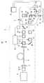
以下、本発明の第1の実施形態に係る多光子励起走査型レーザ顕微鏡について、図1を参照して以下に説明する。
本実施形態に係る多光子励起走査型レーザ顕微鏡1は、図1に示されるように、照明装置2と、顕微鏡本体3と、画像表示装置4とを備えている。Hereinafter, a multiphoton excitation scanning laser microscope according to the first embodiment of the present invention will be described with reference to FIG.
As shown in FIG. 1, the multiphoton excitation
本実施形態に係る照明装置2は、図1に示されるように、フェムト秒オーダーの超短パルスレーザ光L1を出射するレーザ光源5と、該レーザ光源5から発せられた超短パルスレーザ光L1の光軸の位置および角度を調節するアライメント調整光学系6と、アライメント調整された超短パルスレーザ光L1を集光させるカップリング光学系7と、該カップリング光学系7による集光位置に一端を配置したフォトニックバンドギャップ材からなる光ファイバ8と、光ファイバ8から出射される超短パルスレーザ光L2を略平行光に変換するコリメート光学系9と、略平行光にされたレーザ光L2の光束径およびビームダイバージェンスを調節するビーム整形光学系10とを備えている。また、ビーム整形光学系10の前段には、超短パルスレーザ光L2の群速度分散を補償する分散補償光学系31が備えられている。
レーザ光源5は、例えば、波長800nmの超短パルスレーザ光L1を出射するようになっている。As shown in FIG. 1, the
For example, the
前記アライメント調整光学系6は、例えば、光軸に対して垂直な2軸の傾き角を調節できる2枚の反射ミラーおよびビーム位置検出光学系により構成されている、これにより、アライメント調整光学系6は、レーザ光源5から出射された超短パルスレーザ光L1の光束の中心位置を光ファイバ8の入射光軸に一致させるように調節できる。 The alignment adjustment
前記光ファイバ8は、例えば、フォトニッククリスタルファイバあるいはテーパファイバにより構成されている。これにより、光ファイバ8は、一端から入射される波長800nmの超短パルスレーザ光L1を伝播させる間にスペクトル拡散させて、略300〜1600nmの波長帯域を有する白色の超短パルスレーザ光L2を他端から出射させるようになっている。 The
前記ビーム整形光学系10は、例えば、両凸レンズと平凹レンズとを組み合わせたガリレイ型のビームエキスパンダにより構成されている。これにより、顕微鏡本体に入射される超短パルスレーザ光L2が、後述する対物レンズ15の入射瞳位置において、その瞳径と略同等の光束径を有するように、その光束径およびビームダイバージェンスを補正するようになっている。 The beam shaping
前記顕微鏡本体3は、筐体11内に、照明装置2から出射されてきた略平行光からなる白色の超短パルスレーザ光L2を2次元的に走査するスキャナ12と、走査された超短パルスレーザ光L2を集光して中間像を結像させる瞳投影レンズ13と、中間像を結像した超短パルスレーザ光を集光する結像レンズ14と、結像レンズ14から発せられた超短パルスレーザ光L2を集光して標本Aに再結像させる対物レンズ15と、標本Aにおいて発生し、対物レンズ15により集められた多光子蛍光Fを超短パルスレーザ光L2から分岐するダイクロイックミラー16と、分岐された多光子蛍光の波長を選択する波長選択素子(波長選択光学系)50と、集光レンズ17と、多光子蛍光Fを撮像する光検出器18とを備えている。 The microscope
スキャナ12は、例えば、互いに直交する2本の軸線回りに揺動させられる2枚のガルバノミラー(図示略)を近接配置してなる、いわゆる近接ガルバノミラーにより構成されている。
前記光検出器18は、例えば、光電子増倍管(PMT:Photo Multiplier Tube)であり、複数、例えば2つ設けられている。波長選択光学系50は、例えば、ダイクロイックミラー、グレーティングおよびスリット、あるいはこれらの組合せにより構成されている。例えば、標本を異なる蛍光色素で染め、そして、異なる波長域で蛍光を生じさせている場合には、これらを波長選択素子50で分離して、異なる蛍光色素からの異なる波長の蛍光を独立して検出することができる。
前記画像表示装置4は、光検出器18により検出された標本Aからの多光子蛍光Fに基づいて構成された多光子蛍光画像を表示するようになっている。The
The
The image display device 4 is configured to display a multiphoton fluorescence image configured based on the multiphoton fluorescence F from the specimen A detected by the
このように構成された本実施形態に係る多光子励起走査型レーザ顕微鏡1の作用について、以下に説明する。
レーザ光源5から出射された超短パルスレーザ光L1は、アライメント調整光学系6によってその光軸位置および角度を調節された後に、カップリング光学系7により集光されて光ファイバ8に入射させられる。The operation of the thus configured multi-photon excitation
The ultrashort pulse laser beam L1 emitted from the
光ファイバ8に入射された超短パルスレーザ光L1は、フォトニックバンドギャップ材からなる光ファイバ8の非線形効果によってスペクトル拡散させられて、波長300〜1600nmの広い波長帯域を有する白色の超短パルスレーザ光L2として光ファイバ8の他端から出射される。そして、出射された白色の超短パルスレーザ光L2は、コリメート光学系9によって略平行光にされた後にビーム整形光学系10によって、その光束径およびビームダイバージェンスを調節された状態で、顕微鏡本体3に向けて出射される。 The ultrashort pulse laser light L1 incident on the
そして、顕微鏡本体3に入射された超短パルスレーザ光L2は、スキャナ12により2次元的に走査されつつ、瞳投影レンズ13,結像レンズ14、蛍光の波長域をカットするダイクロイックミラー16および対物レンズ15を介して標本Aの所定の深さ位置に集光され、その位置において多光子励起効果を発生させる。
また、超短パルスレーザ光L2は、アライメント調整光学系6によりその光軸位置および角度を調節され、かつ、ビーム整形光学系10によりその光束径およびビームダイバージェンスを調節されているので、標本Aの所定の深さ位置に高い精度で集光される。したがって、明るくかつ空間分解能の高い多光子蛍光画像を取得することができる。The ultrashort pulse laser beam L2 incident on the microscope
The ultrashort pulse laser beam L2 has its optical axis position and angle adjusted by the alignment adjustment
さらに、超短パルスレーザ光L2は、分散補償光学系31の作動により、系全体の群速度分散が補償される。これにより、パルス幅の太りが補正され、標本Aにおける集光位置において、効率的な多光子励起効果を発生させることができる。 Furthermore, the group velocity dispersion of the entire system of the ultrashort pulse laser beam L2 is compensated by the operation of the dispersion compensation
本実施形態に係る多光子励起走査型レーザ顕微鏡1によれば、白色の超短パルスレーザ光L2を標本Aに集光するので、標本Aに複数の蛍光物質を含有させておけば、白色の超短パルスレーザ光L2に含まれる複数の波長帯域の超短パルスレーザ光によって、複数の波長の多光子蛍光Fを同時に発生させることができる。
そして、本実施形態に係る多光子励起走査型レーザ顕微鏡1によれば、このような効果を単一の波長(800nm)の超短パルスレーザ光L1のみを出射可能な小型のレーザ光源5により達成できる。したがって、大型かつ高価な波長可変のレーザ光源を使用する必要がなく、多光子励起走査型レーザ顕微鏡1の小型化およびコストの低減を図ることができるという効果がある。According to the multiphoton excitation
Then, according to the multiphoton excitation
なお、本実施形態に係る多光子励起走査型レーザ顕微鏡1においては、光ファイバ8から出射された白色の超短パルスレーザ光L2をそのままビーム整形光学系10によりビーム整形して顕微鏡本体3に入射させることとしたが、これに代えて、図2に示されるように、顕微鏡本体3に入射させる超短パルスレーザ光L2の波長域を制限するカラーフィルタあるいはバンドパスフィルタ19を配置してもよい。このように構成することで、不要光を含まない超短パルスレーザ光L2を顕微鏡本体3に入射させることができ、ノイズを低減して分解能の高い多光子蛍光画像を取得することが可能となる。 In the multiphoton excitation
次に、本発明の第2の実施形態に係る多光子励起走査型レーザ顕微鏡20について、図3を参照して以下に説明する。
本実施形態の説明において、上述した第1の実施形態に係る多光子励起走査型レーザ顕微鏡1と構成を共通とする箇所に同一符号を付して説明を省略する。Next, a multiphoton excitation
In the description of the present embodiment, the same reference numerals are given to portions having the same configuration as the multiphoton excitation
本実施形態に係る多光子励起走査型レーザ顕微鏡20は、コリメート光学系9とビーム整形光学系10との間に、コリメート光学系9から出射された白色の超短パルスレーザ光L2の波長域とスペクトルの幅とを調節する波長選択光学系21と、超短パルスレーザ光L2の強度を調節する強度調整光学系22とを備えている。 The multiphoton excitation
波長選択光学系21としては、例えば、音響光学素子(AOTF,AOM,AOBS)、電気光学素子(EOM)、フィルタ(カラーフィルタ、バンドパスフィルタ、バイパスフィルタ)、グレーティングとスリット、プリズムとスリット、エタロンとスリットまたは軸上収差の大きい色消しレンズとピンホールが挙げられる。
強度調整光学系22としては、音響光学素子(AOTF,AOM,AOBS)、電気光学素子(EOM)、偏光板、可変NDフィルタ、可変絞り等が挙げられる。Examples of the wavelength selection
Examples of the intensity adjustment
また、ビーム整形光学系10と顕微鏡本体3との間にビーム整形光学系10を通過した超短パルスレーザ光L2の一部を分岐するビームサンプラー23と、分岐された超短パルスレーザ光L2の中心波長およびスペクトル波形を検出する分光器24と、検出された超短パルスレーザ光L2の中心波長およびスペクトル波形の幅、強度に基づいて前記波長選択光学系21および強度調整光学系22を制御する制御装置25とを備えている。 Further, between the beam shaping
本実施形態に係る多光子励起走査型レーザ顕微鏡20によれば、制御装置25において、標本Aに照射する超短パルスレーザ光L3の中心波長、スペクトル幅および強度を設定することにより、波長選択光学系21の作動により白色の超短パルスレーザ光L2から切り出す超短パルスレーザ光L3の中心波長およびスペクトル幅が設定され、また、強度調整光学系22の作動により、切り出された超短パルスレーザ光L3の強度が設定される。 According to the multiphoton excitation
また、本実施形態によれば、ビーム整形光学系10から出射された超短パルスレーザ光L3が分光器により分光され、得られた中心波長およびスペクトル波形が制御装置25に送られる。したがって、制御装置25は、ビーム整形光学系10からの超短パルスレーザ光L3の中心波長およびスペクトル波形の幅、強度を、波長選択光学系21および強度調整光学系22にフィードバックして、所望の中心波長、スペクトル幅および強度を有する超短パルスレーザ光L3を顕微鏡本体3に入力させることができる。 Further, according to the present embodiment, the ultrashort pulsed laser light L3 emitted from the beam shaping
なお、本実施形態に係る多光子励起走査型レーザ顕微鏡20においては、コリメート光学系9とビーム整形光学系10との間に波長選択光学系21および強度調整光学系22を設け、光ファイバ8を通過してスペクトル拡散された白色の超短パルスレーザ光L2の中心波長、スペクトル幅および強度を調節することとしたが、これに代えて、図4に示されるように、光ファイバ8への入射前に出力調節光学系26を設け、光ファイバ8へ入射する超短パルスレーザ光L1の尖頭出力を調節することで、超短パルスレーザ光L2の中心波長、スペクトル幅および強度を調整をすることとしてもよい。 In the multiphoton excitation
これは、光ファイバ8において発生する非線形効果の強さが超短パルスレーザ光の尖頭出力(ピーク強度)に応じて変化することを利用するものである。尖頭出力の調整には超短パルスレーザ光の強度(エネルギ)を減少させる方法と、強度(エネルギ)を変えずにパルス幅を変化させる方法がある。強度(エネルギ)を低下させるには、前述の強度調整光学系と同じもの(例えば、音響光学素子、可変NDフィルタ等)を使用できる。 This utilizes the fact that the strength of the nonlinear effect generated in the
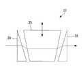
エネルギを保持してパルス幅を変化させるには、出力調節光学系26として、例えば、プリズム対、グレーティング対または分散素子27からなるパルス幅調整光学系を配置して、超短パルスレーザ光L1のパルス幅を制御することで、超短パルスレーザ光L2の中心波長、スペクトル幅および強度を調整する。分散素子27としては、例えば、図5に示されるように、一対の三角プリズム28と台形プリズム29とを並べて配置し、台形プリズム29を光軸に交差する方向に移動させる方式のものが挙げられる。 In order to change the pulse width while maintaining energy, for example, a pulse width adjustment optical system including a prism pair, a grating pair, or a
次に、本発明の第3の実施形態に係る多光子励起走査型レーザ顕微鏡30について、図6を参照して以下に説明する。
本実施形態の説明において、上述した第2の実施形態に係る多光子励起走査型レーザ顕微鏡20と構成を共通とする箇所に同一符号を付して説明を省略する。Next, a multiphoton excitation
In the description of the present embodiment, the same reference numerals are given to portions having the same configuration as the multi-photon excitation
本実施形態に係る多光子励起走査型レーザ顕微鏡30は、波長選択光学系21の後段に、波長選択光学系21によって切り出された所定の中心波長およびスペクトル幅を有する超短パルスレーザ光L3に対する群速度分散を補償する分散補償光学系31を備えている。
分散補償光学系31は、プリズム対またはグレーティング対からなり、プリズム間隔あるいはグレーティング間隔を調節することで、分散補償量を調節することができるようになっている。The multiphoton excitation
The dispersion compensation
本実施形態においては、制御装置25が分散補償光学系31にも接続され、ビーム整形光学系10から出射された超短パルスレーザ光L3の中心波長を元に、予め図示しない記憶装置内に記録された顕微鏡全体の分散を補償するための波長毎のプリズム間隔あるいはグレーティング間隔になるように、分散補償光学系31を調節するようになっている。 In the present embodiment, the
このように構成された本実施形態に係る多光子励起走査型レーザ顕微鏡30によれば、分散補償光学系31の作動により、波長毎の群速度分散を補償して、標本Aに到達する時点の超短パルスレーザ光L3のパルス波形を最適にすることができるようになっている。また、波長選択光学系21により選択される超短パルスレーザ光L3の波長が変更されても、分光器により検出した超短パルスレーザ光L3の中心波長に基づいて、制御装置が分散補償光学系31を制御するので、超短パルスレーザ光L3のパルス波形が標本Aへの到達時にも最適になっており、標本Aにおいて多光子励起効果を効率的に発生させ、多光子励起画像の分解能を向上することができる。 According to the multi-photon excitation
次に、本発明の第4の実施形態に係る多光子励起走査型レーザ顕微鏡40について、図7および図8を参照して以下に説明する。
本実施形態の説明において、上述した第2の実施形態に係る多光子励起走査型レーザ顕微鏡20と構成を共通とする箇所に同一符号を付して説明を省略する。Next, a multiphoton excitation
In the description of the present embodiment, the same reference numerals are given to portions having the same configuration as the multi-photon excitation
本実施形態に係る多光子励起走査型レーザ顕微鏡40は、コリメート光学系9から出射された白色の超短パルスレーザ光L2から所定波長の超短パルスレーザ光L4と残りの超短パルスレーザ光L3とに分離する波長選択光学系21′と、分離された所定波長の超短パルスレーザ光L4の位置を調節する第2のスキャナ(第2のレーザ走査部)41と、該第2のスキャナ41により位置調節された超短パルスレーザ光L4を集光する瞳投影レンズ42と、該瞳投影レンズ42により集光された超短パルスレーザ光L4を、スキャナ12により走査された残りの超短パルスレーザ光L3に合波させるダイクロイックミラー(合波部材)43とを備えている。 The multiphoton excitation
本実施形態においては、分光器24は、所定波長の超短パルスレーザ光L4を切り出されることにより、図8に示されるようなスペクトル波形を有する超短パルスレーザ光L3に基づいて、超短パルスレーザ光L4の中心波長を検出するようになっている。また、制御装置25は、検出された超短パルスレーザ光L4の中心波長に基づいて前記波長選択光学系21および超短パルスレーザ光L4の光路に配置された分散補償光学系31を制御するようになっている。図中、符号44はミラーである。 In the present embodiment, the
このように構成された本実施形態に係る多光子励起走査型レーザ顕微鏡40によれば、光ファイバ8を通過させられることにより、略300〜1600nmの波長帯域を有するようにスペクトル拡散された白色の超短パルスレーザ光L2が、波長選択光学系21′を通過させられることにより、所定波長の超短パルスレーザ光L4と残りの超短パルスレーザ光L3とに分離される。 According to the multi-photon excitation
分離された2つの超短パルスレーザ光L3,L4は、それぞれ分散補償光学系31を通過させられることにより群速度分散が補償され、ビーム整形光学系10を通過させられることにより、それらの光束径およびビームダイバージェンスが調節される。
ビームサンプラー23により分岐された超短パルスレーザ光L3は、図8に示されるように、切り出された超短パルスレーザ光L4部分の欠落したスペクトル波形を有しているので、分光器24において超短パルスレーザ光L4の中心波長を容易に求めることができる。The separated two ultrashort pulse laser beams L3 and L4 are each passed through the dispersion compensation
As shown in FIG. 8, the ultrashort pulse laser beam L3 branched by the
そして、求められた超短パルスレーザ光L4の中心波長に基づいて、波長選択光学系21の切り出す波長がフィードバック調節される一方、分散補償光学系31による超短パルスレーザ光L4の分散補償量が波長に合わせて調節される。
したがって、超短パルスレーザ光L4は、波長選択光学系21′により、所望の中心波長を有するように精度よく切り出され、分散補償光学系31により波長に合わせた分散補償量で適正に群速度分散を補償され、ビーム整形光学系10により光束径およびビームダイバージェンスを調節された状態で顕微鏡本体3に入射される。
そして、このようにして理想的に調節された超短パルスレーザ光L4は、第2のスキャナ41により2次元的に走査され、あるいは、2次元的な位置を設定される。その後、瞳投影レンズ42、ダイクロイックミラー43、結像レンズ14および対物レンズ15を介して標本Aに照射される。Based on the obtained center wavelength of the ultrashort pulse laser light L4, the wavelength extracted by the wavelength selection
Accordingly, the ultrashort pulse laser beam L4 is accurately cut out by the wavelength selection optical system 21 'so as to have a desired center wavelength, and the group velocity dispersion is appropriately performed with the dispersion compensation amount according to the wavelength by the dispersion compensation
Then, the ultrashort pulse laser beam L4 ideally adjusted in this way is scanned two-dimensionally by the
一方、波長選択光学系21により超短パルスレーザ光L4を切り出された残りの超短パルスレーザ光L3は、分散補償光学系31により波長に合わせた分散補償量で適正に群速度分散を補償され、ビーム整形光学系10により光束径およびビームダイバージェンスを調節された状態で顕微鏡本体3に入射される。そして、顕微鏡本体3内においては、超短パルスレーザ光L3は、スキャナ12により2次元的に走査され、瞳投影レンズ、結像レンズおよび対物レンズを透過して標本Aに照射される。 On the other hand, the remaining ultrashort pulse laser beam L3 obtained by cutting out the ultrashort pulse laser beam L4 by the wavelength selection
標本Aに照射される超短パルスレーザ光L3は、超短パルスレーザ光L4の波長が欠落したスペクトル波形を有しているが、複数の波長帯域の超短パルスレーザ光が含まれているので、複数の波長の多光子蛍光Fを同時に発生させることができる。
また、標本Aに照射される超短パルスレーザ光L4は、極めて精度よく限定された波長を有し、かつ、厳密に分散補償されているので、精度の高い多光子励起刺激を標本Aに付与することができる。The ultrashort pulse laser beam L3 irradiated to the specimen A has a spectrum waveform in which the wavelength of the ultrashort pulse laser beam L4 is missing, but includes ultrashort pulse laser beams in a plurality of wavelength bands. The multiphoton fluorescence F having a plurality of wavelengths can be generated simultaneously.
In addition, the ultrashort pulse laser beam L4 irradiated on the specimen A has a limited wavelength with extremely high accuracy and is strictly dispersion-compensated, so that highly accurate multiphoton excitation stimulation is given to the specimen A. can do.
このように、本実施形態に係る多光子励起走査型レーザ顕微鏡40によれば、単一の光源で多光子励起刺激と、複数波長による多光子蛍光観察を行うことができ、製品コストを低減することができる。また、多光子励起刺激と複数波長による多光子蛍光観察を同時タイミングで行うことができる。したがって、標本Aにおいて瞬時に発生する現象を逃すことなく観察できるという利点がある。 As described above, according to the multiphoton excitation
なお、本実施形態においては、第2のスキャナ41により超短パルスレーザ光L4の標本Aへの照射位置を設定することとしたが、これに代えて、第2のスキャナ41により超短パルスレーザ光L4を走査させることで、標本Aの所望の範囲に多光子励起刺激を与え
ることとしてもよい。In this embodiment, the irradiation position of the ultrashort pulse laser beam L4 on the specimen A is set by the
また、分散補償光学系31により、超短パルスレーザ光L4のパルス幅を太らせることにより、波長選択光学系21′により選択された中心波長に応じた1光子励起刺激を行うことができる。 Further, by increasing the pulse width of the ultrashort pulse laser beam L4 by the dispersion compensation
A 標本
F 多光子蛍光
L1,L2,L3,L4 超短パルスレーザ光
1,20,30,40 多光子励起走査型レーザ顕微鏡
5 レーザ光源
8 光ファイバ
12 スキャナ(レーザ走査部)
15 対物レンズ(対物光学系)
18 光検出器
19,21,21′ 波長選択光学系
24 分光器(波形検出部)
25 制御装置(調節装置:波長調節部:分散補償量調節装置)
26 出力調節光学系(尖頭出力調整光学系)
31 分散補償光学系
41 第2のスキャナ(第2のレーザ走査部)
43 ダイクロイックミラー(合波部材)A Specimen F Multiphoton fluorescence L1, L2, L3, L4 Ultrashort
15 Objective lens (objective optical system)
18
25 Control device (Adjustment device: Wavelength adjustment unit: Dispersion compensation amount adjustment device)
26 Output adjustment optical system (peak output adjustment optical system)
31 Dispersion compensation
43 Dichroic mirror
Claims (9)
Translated fromJapanese該レーザ光源からの超短パルスレーザ光を入射させ、超短パルスレーザ光のスペクトルを拡散させる光ファイバと、
該光ファイバから出射されたスペクトル拡散された超短パルスレーザ光を走査するレーザ走査部と、
該レーザ走査部により走査された超短パルスレーザ光を標本に集光させる対物光学系と、
標本における超短パルスレーザ光の集光位置から発せられた多光子蛍光を検出する光検出器と、
前記超短パルスレーザ光に対する群速度分散を補償する分散補償光学系と、
前記光ファイバから出射されたスペクトル拡散された超短パルスレーザ光の波長を選択する波長選択光学系と、
前記波長選択光学系により波長選択された超短パルスレーザ光の中心波長に基づいて、前記分散補償光学系の分散補償量を調節する調節装置とを備え、
前記分散補償光学系が、前記光ファイバ出射側に配置されている多光子励起走査型レーザ顕微鏡。A laser light source that emits a single-wavelength ultrashort pulse laser beam;
An optical fiber that makes ultrashort pulse laser light from the laser light source incident thereon and diffuses the spectrum of the ultrashort pulse laser light;
A laser scanning unit that scans the spectrum-spread ultrashort pulse laser beam emitted from the optical fiber;
An objective optical system for condensing an ultrashort pulse laser beam scanned by the laser scanning unit on a specimen;
A photodetector for detecting the multiphoton fluorescence emitted from the focal position of the ultrashort pulse laser beam in the specimen;
A dispersion compensation optical system for compensating for group velocity dispersion for the ultrashort pulse laser beam;
A wavelength selection optical system for selecting the wavelength of the spectrum-spread ultrashort pulse laser beam emitted from the optical fiber;
An adjustment device that adjusts the dispersion compensation amount of the dispersion compensation optical system based on the center wavelength of the ultrashort pulse laser light that has been wavelength-selected by the wavelength selection optical system;
The multiphoton excitation scanning laser microscopein which the dispersion compensation optical system is disposed on the optical fiber emission side .
該レーザ光源からの超短パルスレーザ光を入射させ、超短パルスレーザ光のスペクトルを拡散させる光ファイバと、
該光ファイバから出射されたスペクトル拡散された超短パルスレーザ光を走査するレーザ走査部と、
該レーザ走査部により走査された超短パルスレーザ光を標本に集光させる対物光学系と、
標本における超短パルスレーザ光の集光位置から発せられた多光子蛍光を検出する光検出器と、
前記超短パルスレーザ光に対する群速度分散を補償する分散補償光学系と、
前記光ファイバから出射されたスペクトル拡散された超短パルスレーザ光の波長を選択する波長選択光学系と、
前記波長選択光学系により波長選択された超短パルスレーザ光の中心波長を検出する波形検出部と、
前記波形検出部により検出された中心波長に基づいて、前記分散補償光学系の分散補償量を調節する調節装置とを備え、
前記分散補償光学系が、前記光ファイバ出射側に配置されている多光子励起走査型レーザ顕微鏡。A laser light source that emits a single-wavelength ultrashort pulse laser beam;
An optical fiber that makes ultrashort pulse laser light from the laser light source incident thereon and diffuses the spectrum of the ultrashort pulse laser light;
A laser scanning unit that scans the spectrum-spread ultrashort pulse laser beam emitted from the optical fiber;
An objective optical system for condensing an ultrashort pulse laser beam scanned by the laser scanning unit on a specimen;
A photodetector for detecting the multiphoton fluorescence emitted from the focal position of the ultrashort pulse laser beam in the specimen;
A dispersion compensation optical system for compensating for group velocity dispersion for the ultrashort pulse laser beam;
A wavelength selection optical system for selecting the wavelength of the spectrum-spread ultrashort pulse laser beam emitted from the optical fiber;
A waveform detector that detects the center wavelength of the ultrashort pulse laser beam that has been wavelength-selected by the wavelength-selective optical system;
An adjustment device for adjusting a dispersion compensation amount of the dispersion compensation optical system based on a center wavelength detected by the waveform detector;
The multiphoton excitation scanning laser microscopein which the dispersion compensation optical system is disposed on the optical fiber emission side .
該レーザ光源からの超短パルスレーザ光を入射させ、超短パルスレーザ光のスペクトルを拡散させる光ファイバと、
前記光ファイバから出射されたスペクトル拡散された超短パルスレーザ光から所定波長の超短パルスレーザ光を選択的に分離する波長選択光学系と、
該波長選択光学系により所定波長の超短パルスレーザ光が分離された残りの超短パルスレーザ光を走査するレーザ走査部と、
該レーザ走査部により走査された残りの超短パルスレーザ光に、前記所定波長の超短パルスレーザ光を合波させる合波部材と、
該合波部材により合波された超短パルスレーザ光を標本に集光させる対物光学系と、
標本における超短パルスレーザ光の集光位置から発せられた多光子蛍光を検出する光検出器と、
前記波長選択光学系により分離された所定波長の超短パルスレーザ光に対する群速度分散を補償する第1の分散補償光学系と、
残りの超短パルスレーザ光に対する群速度分散を補償する第2の分散補償光学系とを備える多光子励起走査型レーザ顕微鏡。A laser light source that emits a single-wavelength ultrashort pulse laser beam;
An optical fiber that makes ultrashort pulse laser light from the laser light source incident thereon and diffuses the spectrum of the ultrashort pulse laser light;
A wavelength selection optical system that selectively separates an ultrashort pulse laser beam having a predetermined wavelength from an ultrashort pulse laser beam that has been spread out from the optical fiber;
A laser scanning unit that scans the remaining ultrashort pulse laser light from which the ultrashort pulse laser light having a predetermined wavelength is separated by the wavelength selection optical system;
A multiplexing member for multiplexing the ultra-short pulse laser beam having the predetermined wavelength with the remaining ultra-short pulse laser beam scanned by the laser scanning unit;
An objective optical system for condensing the ultrashort pulse laser beam combined by the combining member on the sample;
A photodetector for detecting the multiphoton fluorescence emitted from the focal position of the ultrashort pulse laser beam in the specimen;
A first dispersion compensation optical system for compensating for group velocity dispersion for an ultrashort pulse laser beam having a predetermined wavelength separated by the wavelength selection optical system;
A multiphoton excitation scanning laser microscope comprising: asecond dispersion compensation optical system that compensates group velocity dispersion for the remaining ultrashort pulse laser light .
前記波形検出部により検出された中心波長に基づいて、前記波長選択光学系により分離する超短パルスレーザ光の波長を調節する波長調節装置とを備える請求項3に記載の多光子励起走査型レーザ顕微鏡。A waveform detection unit for detecting a center wavelength of the ultrashort pulse laser beam having a predetermined wavelength separated by the wavelength selection optical system;
The multiphoton excitation scanning laser according to claim3 , further comprising: a wavelength adjusting device that adjusts a wavelength of the ultrashort pulse laser beam separated by the wavelength selection optical system based on a center wavelength detected by the waveform detection unit. microscope.
Priority Applications (2)
| Application Number | Priority Date | Filing Date | Title |
|---|---|---|---|
| JP2006046768AJP4869734B2 (en) | 2005-04-25 | 2006-02-23 | Multi-photon excitation scanning laser microscope |
| US11/407,300US7329880B2 (en) | 2005-04-25 | 2006-04-19 | Multiphoton-excitation laser scanning microscope |
Applications Claiming Priority (3)
| Application Number | Priority Date | Filing Date | Title |
|---|---|---|---|
| JP2005126592 | 2005-04-25 | ||
| JP2005126592 | 2005-04-25 | ||
| JP2006046768AJP4869734B2 (en) | 2005-04-25 | 2006-02-23 | Multi-photon excitation scanning laser microscope |
Publications (3)
| Publication Number | Publication Date |
|---|---|
| JP2006330685A JP2006330685A (en) | 2006-12-07 |
| JP2006330685A5 JP2006330685A5 (en) | 2009-04-09 |
| JP4869734B2true JP4869734B2 (en) | 2012-02-08 |
Family
ID=37185903
Family Applications (1)
| Application Number | Title | Priority Date | Filing Date |
|---|---|---|---|
| JP2006046768AExpired - Fee RelatedJP4869734B2 (en) | 2005-04-25 | 2006-02-23 | Multi-photon excitation scanning laser microscope |
Country Status (2)
| Country | Link |
|---|---|
| US (1) | US7329880B2 (en) |
| JP (1) | JP4869734B2 (en) |
Families Citing this family (34)
| Publication number | Priority date | Publication date | Assignee | Title |
|---|---|---|---|---|
| JP4759425B2 (en)* | 2006-03-28 | 2011-08-31 | オリンパス株式会社 | Multiphoton excitation observation device |
| US20080001320A1 (en) | 2006-06-28 | 2008-01-03 | Knox Wayne H | Optical Material and Method for Modifying the Refractive Index |
| JP4855237B2 (en)* | 2006-12-20 | 2012-01-18 | オリンパス株式会社 | Microscope image processing apparatus and microscope image processing program |
| JP2008185432A (en)* | 2007-01-30 | 2008-08-14 | Yokogawa Electric Corp | Drug discovery screening device |
| EP1959292A3 (en)* | 2007-02-13 | 2009-06-17 | Olympus Corporation | Laser microscope |
| JP5096760B2 (en)* | 2007-02-23 | 2012-12-12 | オリンパス株式会社 | Microscope illumination device and fluorescence microscope device |
| JP2008225095A (en)* | 2007-03-13 | 2008-09-25 | Olympus Corp | Optical scan type observation device |
| JP5281756B2 (en)* | 2007-04-13 | 2013-09-04 | オリンパス株式会社 | Scanning optical apparatus and observation method |
| JP5307439B2 (en)* | 2007-04-23 | 2013-10-02 | オリンパス株式会社 | Laser microscope |
| DE102007028337B4 (en)* | 2007-06-15 | 2019-08-29 | Leica Microsystems Cms Gmbh | Beam combiner and a light source with such a beam combiner |
| JP2011501189A (en)* | 2007-10-25 | 2011-01-06 | ザ・リサーチ・ファウンデーション・オブ・ステイト・ユニバーシティー・オブ・ニューヨーク | Single photon spectrometer |
| JP5185695B2 (en)* | 2008-05-23 | 2013-04-17 | オリンパス株式会社 | Laser microscope apparatus and specimen image acquisition method |
| JP5203063B2 (en)* | 2008-06-24 | 2013-06-05 | オリンパス株式会社 | Multiphoton excitation measurement system |
| WO2011038349A1 (en)* | 2009-09-28 | 2011-03-31 | Purdue Research Foundation | Multiphoton luminescence imaging of protein crystals |
| DE102009048710B4 (en)* | 2009-10-08 | 2020-04-02 | Leica Microsystems Cms Gmbh | Laser system for a microscope and method for operating a laser system for a microscope |
| EP2312367A1 (en)* | 2009-10-16 | 2011-04-20 | Olympus Corporation | Laser scanning microscope |
| WO2011056658A1 (en)* | 2009-10-27 | 2011-05-12 | Duke University | Multi-photon microscopy via air interface objective lens |
| JP2011128288A (en)* | 2009-12-16 | 2011-06-30 | Nikon Corp | Pulse division device, multiphoton microscope, and pulse dividing element |
| JP2011128287A (en)* | 2009-12-16 | 2011-06-30 | Nikon Corp | Multiphoton microscope |
| KR101200536B1 (en)* | 2010-05-26 | 2012-11-13 | 한국과학기술연구원 | Beam scanning system for detecting bio-material |
| ITRM20100286A1 (en)* | 2010-05-28 | 2011-11-29 | Consiglio Nazionale Ricerche | SPECTRAL CONFOCAL MICROSCOPE IN REFLECTION WITH A WIDE BAND. |
| DE102010047237B4 (en)* | 2010-08-13 | 2021-07-01 | Leica Microsystems Cms Gmbh | Method for separating detection signals in the beam path of an optical device |
| DE102010037190B4 (en) | 2010-08-27 | 2015-11-26 | Leica Microsystems Cms Gmbh | Device for temporally shifting white light laser pulses |
| US9494781B2 (en)* | 2011-01-19 | 2016-11-15 | California Institute Of Technology | Plane-projection multi-photon microscopy |
| DE102011000905A1 (en)* | 2011-02-24 | 2012-08-30 | Leica Microsystems Cms Gmbh | Pulse combiner for the different spectral colors of a supercontinuum laser |
| JP5616824B2 (en) | 2011-03-10 | 2014-10-29 | オリンパス株式会社 | Microscope equipment |
| JP5839897B2 (en)* | 2011-09-02 | 2016-01-06 | オリンパス株式会社 | Nonlinear optical microscope |
| DE102012009780A1 (en)* | 2012-05-18 | 2013-11-21 | Leica Microsystems Cms Gmbh | Method and device for examining a sample |
| JP6501451B2 (en)* | 2014-03-31 | 2019-04-17 | キヤノン株式会社 | Light source device and information acquisition device using the same |
| US9653867B2 (en) | 2014-04-04 | 2017-05-16 | Coherent, Inc. | Multi-wavelength source of femtosecond infrared pulses |
| WO2016206700A1 (en)* | 2015-06-25 | 2016-12-29 | Nkt Photonics A/S | A delivery fiber assembly and a broad band source |
| CN106444245A (en)* | 2016-08-26 | 2017-02-22 | 湖北久之洋红外系统股份有限公司 | Speckle-free three-primary-color laser light source |
| US10394008B2 (en)* | 2016-10-19 | 2019-08-27 | Cornell University | Hyperspectral multiphoton microscope for biomedical applications |
| JP2019207338A (en) | 2018-05-30 | 2019-12-05 | オリンパス株式会社 | Observation device and objective lens |
Family Cites Families (21)
| Publication number | Priority date | Publication date | Assignee | Title |
|---|---|---|---|---|
| JPH03294815A (en)* | 1990-04-13 | 1991-12-26 | Nippon Telegr & Teleph Corp <Ntt> | Ultrashort light pulse supply device |
| US6485413B1 (en)* | 1991-04-29 | 2002-11-26 | The General Hospital Corporation | Methods and apparatus for forward-directed optical scanning instruments |
| DE19622359B4 (en)* | 1996-06-04 | 2007-11-22 | Carl Zeiss Jena Gmbh | Device for coupling the radiation of short-pulse lasers in a microscopic beam path |
| JP3917731B2 (en)* | 1996-11-21 | 2007-05-23 | オリンパス株式会社 | Laser scanning microscope |
| DE19827139C2 (en)* | 1998-06-18 | 2002-01-31 | Zeiss Carl Jena Gmbh | Microscope with a short-pulse laser coupled in via an optical fiber |
| DE19827140C2 (en)* | 1998-06-18 | 2002-12-12 | Zeiss Carl Jena Gmbh | Laser scanning microscope with AOTF |
| JP4282839B2 (en)* | 1999-08-20 | 2009-06-24 | 独立行政法人科学技術振興機構 | Ultrashort pulse broadband light wave generation method and apparatus |
| EP1164406B1 (en)* | 2000-06-17 | 2019-04-17 | Leica Microsystems CMS GmbH | Method and device for illuminating an object |
| DE20122782U1 (en)* | 2000-06-17 | 2007-11-15 | Leica Microsystems Cms Gmbh | lighting device |
| US6898367B2 (en) | 2000-06-17 | 2005-05-24 | Leica Microsystems Heidelberg Gmbh | Method and instrument for microscopy |
| JP4845279B2 (en) | 2001-02-09 | 2011-12-28 | オリンパス株式会社 | Biological function measurement method |
| DE10120425C2 (en) | 2001-04-26 | 2003-12-18 | Leica Microsystems | scanning microscope |
| JP3829749B2 (en)* | 2002-03-29 | 2006-10-04 | 株式会社島津製作所 | Fluorescence sample observation method and apparatus using multiphoton excitation |
| JP4521155B2 (en)* | 2002-11-27 | 2010-08-11 | オリンパス株式会社 | Microscope image processing device |
| DE10259443B4 (en)* | 2002-12-19 | 2015-01-22 | Carl Zeiss Microscopy Gmbh | Method and arrangement for the optical examination and / or processing of a sample |
| US6914720B2 (en)* | 2003-03-27 | 2005-07-05 | Riken | Time resolved fluorescence microscope |
| JP4276971B2 (en)* | 2004-03-12 | 2009-06-10 | オリンパス株式会社 | Multi-photon excitation measurement system |
| JP4309787B2 (en)* | 2004-03-12 | 2009-08-05 | オリンパス株式会社 | Multi-photon excitation measurement system |
| DE602005007403D1 (en)* | 2004-03-25 | 2008-07-24 | Olympus Corp | Scanning confocal microscope |
| JP4729269B2 (en)* | 2004-06-01 | 2011-07-20 | オリンパス株式会社 | Laser scanning microscope |
| US7924892B2 (en)* | 2004-08-25 | 2011-04-12 | Kla-Tencor Technologies Corporation | Fiber amplifier based light source for semiconductor inspection |
- 2006
- 2006-02-23JPJP2006046768Apatent/JP4869734B2/ennot_activeExpired - Fee Related
- 2006-04-19USUS11/407,300patent/US7329880B2/ennot_activeExpired - Fee Related
Also Published As
| Publication number | Publication date |
|---|---|
| JP2006330685A (en) | 2006-12-07 |
| US20060237666A1 (en) | 2006-10-26 |
| US7329880B2 (en) | 2008-02-12 |
Similar Documents
| Publication | Publication Date | Title |
|---|---|---|
| JP4869734B2 (en) | Multi-photon excitation scanning laser microscope | |
| US10394008B2 (en) | Hyperspectral multiphoton microscope for biomedical applications | |
| JP5189277B2 (en) | Method and apparatus for inspecting a sample | |
| JP6018263B2 (en) | High resolution microscope and method for 2D or 3D positioning of an object | |
| US7092086B2 (en) | Cars microscope and method for cars microscopy | |
| DE102006056429B3 (en) | Microscope-type imaging device for examining biological and medical test samples, has spatially separating beam splitter for partly separating coherent detection light from incoherent light | |
| US10310243B2 (en) | Device and method for multispot scanning microscopy | |
| US8159663B2 (en) | Laser microscope apparatus having a frequency dispersion adjuster | |
| US20020180965A1 (en) | Method for examining a specimen, and scanning microscope system | |
| JP2012510066A (en) | Resolution-enhanced microscopy | |
| US7394063B2 (en) | Microscope for investigating the lifetime of excited states in a sample | |
| WO2005096058A1 (en) | Scanning microscope and method for examining a sample by using scanning microscopy | |
| JPH11149045A (en) | High compact laser scanning microscope with embedded short pulse laser | |
| JP2006119347A (en) | Laser scanning microscope | |
| Müller et al. | Construction and performance of a custom-built two-photon laser scanning system | |
| US10823948B2 (en) | Microscope for imaging an object | |
| JP2017219400A (en) | Laser microscope | |
| JP2004233351A (en) | Fluorescence detection method | |
| JP4981460B2 (en) | Laser microscope | |
| JP4818634B2 (en) | Scanning fluorescence observation system | |
| JP4994940B2 (en) | Laser scanning microscope | |
| JP4878751B2 (en) | Microscope illumination device and fluorescence microscope device | |
| JP2010160264A (en) | Laser microscope | |
| JP2010060698A (en) | Laser microscopic device | |
| JP2010096667A (en) | Laser microscope device |
Legal Events
| Date | Code | Title | Description |
|---|---|---|---|
| A521 | Written amendment | Free format text:JAPANESE INTERMEDIATE CODE: A523 Effective date:20090223 | |
| A621 | Written request for application examination | Free format text:JAPANESE INTERMEDIATE CODE: A621 Effective date:20090223 | |
| A977 | Report on retrieval | Free format text:JAPANESE INTERMEDIATE CODE: A971007 Effective date:20110714 | |
| A131 | Notification of reasons for refusal | Free format text:JAPANESE INTERMEDIATE CODE: A131 Effective date:20110802 | |
| A521 | Written amendment | Free format text:JAPANESE INTERMEDIATE CODE: A523 Effective date:20110930 | |
| TRDD | Decision of grant or rejection written | ||
| A01 | Written decision to grant a patent or to grant a registration (utility model) | Free format text:JAPANESE INTERMEDIATE CODE: A01 Effective date:20111025 | |
| A01 | Written decision to grant a patent or to grant a registration (utility model) | Free format text:JAPANESE INTERMEDIATE CODE: A01 | |
| A61 | First payment of annual fees (during grant procedure) | Free format text:JAPANESE INTERMEDIATE CODE: A61 Effective date:20111116 | |
| R151 | Written notification of patent or utility model registration | Ref document number:4869734 Country of ref document:JP Free format text:JAPANESE INTERMEDIATE CODE: R151 | |
| FPAY | Renewal fee payment (event date is renewal date of database) | Free format text:PAYMENT UNTIL: 20141125 Year of fee payment:3 | |
| S531 | Written request for registration of change of domicile | Free format text:JAPANESE INTERMEDIATE CODE: R313531 | |
| R350 | Written notification of registration of transfer | Free format text:JAPANESE INTERMEDIATE CODE: R350 | |
| R250 | Receipt of annual fees | Free format text:JAPANESE INTERMEDIATE CODE: R250 | |
| LAPS | Cancellation because of no payment of annual fees |