JP4869039B2 - Chemical container - Google Patents
Chemical containerDownload PDFInfo
- Publication number
- JP4869039B2 JP4869039B2JP2006318718AJP2006318718AJP4869039B2JP 4869039 B2JP4869039 B2JP 4869039B2JP 2006318718 AJP2006318718 AJP 2006318718AJP 2006318718 AJP2006318718 AJP 2006318718AJP 4869039 B2JP4869039 B2JP 4869039B2
- Authority
- JP
- Japan
- Prior art keywords
- container
- path
- air
- chemical
- intermediate member
- Prior art date
- Legal status (The legal status is an assumption and is not a legal conclusion. Google has not performed a legal analysis and makes no representation as to the accuracy of the status listed.)
- Active
Links
Images


Classifications
- A—HUMAN NECESSITIES
- A61—MEDICAL OR VETERINARY SCIENCE; HYGIENE
- A61J—CONTAINERS SPECIALLY ADAPTED FOR MEDICAL OR PHARMACEUTICAL PURPOSES; DEVICES OR METHODS SPECIALLY ADAPTED FOR BRINGING PHARMACEUTICAL PRODUCTS INTO PARTICULAR PHYSICAL OR ADMINISTERING FORMS; DEVICES FOR ADMINISTERING FOOD OR MEDICINES ORALLY; BABY COMFORTERS; DEVICES FOR RECEIVING SPITTLE
- A61J1/00—Containers specially adapted for medical or pharmaceutical purposes
- A61J1/14—Details; Accessories therefor
- A61J1/1412—Containers with closing means, e.g. caps
- A61J1/1418—Threaded type
- A—HUMAN NECESSITIES
- A61—MEDICAL OR VETERINARY SCIENCE; HYGIENE
- A61J—CONTAINERS SPECIALLY ADAPTED FOR MEDICAL OR PHARMACEUTICAL PURPOSES; DEVICES OR METHODS SPECIALLY ADAPTED FOR BRINGING PHARMACEUTICAL PRODUCTS INTO PARTICULAR PHYSICAL OR ADMINISTERING FORMS; DEVICES FOR ADMINISTERING FOOD OR MEDICINES ORALLY; BABY COMFORTERS; DEVICES FOR RECEIVING SPITTLE
- A61J1/00—Containers specially adapted for medical or pharmaceutical purposes
- A61J1/05—Containers specially adapted for medical or pharmaceutical purposes for collecting, storing or administering blood, plasma or medical fluids ; Infusion or perfusion containers
- A61J1/10—Bag-type containers
- B—PERFORMING OPERATIONS; TRANSPORTING
- B65—CONVEYING; PACKING; STORING; HANDLING THIN OR FILAMENTARY MATERIAL
- B65D—CONTAINERS FOR STORAGE OR TRANSPORT OF ARTICLES OR MATERIALS, e.g. BAGS, BARRELS, BOTTLES, BOXES, CANS, CARTONS, CRATES, DRUMS, JARS, TANKS, HOPPERS, FORWARDING CONTAINERS; ACCESSORIES, CLOSURES, OR FITTINGS THEREFOR; PACKAGING ELEMENTS; PACKAGES
- B65D47/00—Closures with filling and discharging, or with discharging, devices
- B65D47/04—Closures with discharging devices other than pumps
- B65D47/06—Closures with discharging devices other than pumps with pouring spouts or tubes; with discharge nozzles or passages
- B65D47/18—Closures with discharging devices other than pumps with pouring spouts or tubes; with discharge nozzles or passages for discharging drops; Droppers
- B—PERFORMING OPERATIONS; TRANSPORTING
- B65—CONVEYING; PACKING; STORING; HANDLING THIN OR FILAMENTARY MATERIAL
- B65D—CONTAINERS FOR STORAGE OR TRANSPORT OF ARTICLES OR MATERIALS, e.g. BAGS, BARRELS, BOTTLES, BOXES, CANS, CARTONS, CRATES, DRUMS, JARS, TANKS, HOPPERS, FORWARDING CONTAINERS; ACCESSORIES, CLOSURES, OR FITTINGS THEREFOR; PACKAGING ELEMENTS; PACKAGES
- B65D51/00—Closures not otherwise provided for
- B65D51/16—Closures not otherwise provided for with means for venting air or gas
- B65D51/1633—Closures not otherwise provided for with means for venting air or gas whereby venting occurs by automatic opening of the closure, container or other element
- A—HUMAN NECESSITIES
- A61—MEDICAL OR VETERINARY SCIENCE; HYGIENE
- A61J—CONTAINERS SPECIALLY ADAPTED FOR MEDICAL OR PHARMACEUTICAL PURPOSES; DEVICES OR METHODS SPECIALLY ADAPTED FOR BRINGING PHARMACEUTICAL PRODUCTS INTO PARTICULAR PHYSICAL OR ADMINISTERING FORMS; DEVICES FOR ADMINISTERING FOOD OR MEDICINES ORALLY; BABY COMFORTERS; DEVICES FOR RECEIVING SPITTLE
- A61J1/00—Containers specially adapted for medical or pharmaceutical purposes
- A61J1/14—Details; Accessories therefor
- A61J1/1443—Containers with means for dispensing liquid medicaments in a filtered or sterile way, e.g. with bacterial filters
- A61J1/145—Containers with means for dispensing liquid medicaments in a filtered or sterile way, e.g. with bacterial filters using air filters
- A—HUMAN NECESSITIES
- A61—MEDICAL OR VETERINARY SCIENCE; HYGIENE
- A61J—CONTAINERS SPECIALLY ADAPTED FOR MEDICAL OR PHARMACEUTICAL PURPOSES; DEVICES OR METHODS SPECIALLY ADAPTED FOR BRINGING PHARMACEUTICAL PRODUCTS INTO PARTICULAR PHYSICAL OR ADMINISTERING FORMS; DEVICES FOR ADMINISTERING FOOD OR MEDICINES ORALLY; BABY COMFORTERS; DEVICES FOR RECEIVING SPITTLE
- A61J1/00—Containers specially adapted for medical or pharmaceutical purposes
- A61J1/14—Details; Accessories therefor
- A61J1/1443—Containers with means for dispensing liquid medicaments in a filtered or sterile way, e.g. with bacterial filters
- A61J1/1456—Containers with means for dispensing liquid medicaments in a filtered or sterile way, e.g. with bacterial filters using liquid filters
- A—HUMAN NECESSITIES
- A61—MEDICAL OR VETERINARY SCIENCE; HYGIENE
- A61J—CONTAINERS SPECIALLY ADAPTED FOR MEDICAL OR PHARMACEUTICAL PURPOSES; DEVICES OR METHODS SPECIALLY ADAPTED FOR BRINGING PHARMACEUTICAL PRODUCTS INTO PARTICULAR PHYSICAL OR ADMINISTERING FORMS; DEVICES FOR ADMINISTERING FOOD OR MEDICINES ORALLY; BABY COMFORTERS; DEVICES FOR RECEIVING SPITTLE
- A61J1/00—Containers specially adapted for medical or pharmaceutical purposes
- A61J1/14—Details; Accessories therefor
- A61J1/1468—Containers characterised by specific material properties
- A—HUMAN NECESSITIES
- A61—MEDICAL OR VETERINARY SCIENCE; HYGIENE
- A61J—CONTAINERS SPECIALLY ADAPTED FOR MEDICAL OR PHARMACEUTICAL PURPOSES; DEVICES OR METHODS SPECIALLY ADAPTED FOR BRINGING PHARMACEUTICAL PRODUCTS INTO PARTICULAR PHYSICAL OR ADMINISTERING FORMS; DEVICES FOR ADMINISTERING FOOD OR MEDICINES ORALLY; BABY COMFORTERS; DEVICES FOR RECEIVING SPITTLE
- A61J1/00—Containers specially adapted for medical or pharmaceutical purposes
- A61J1/14—Details; Accessories therefor
- A61J1/20—Arrangements for transferring or mixing fluids, e.g. from vial to syringe
- A61J1/2003—Accessories used in combination with means for transfer or mixing of fluids, e.g. for activating fluid flow, separating fluids, filtering fluid or venting
- A61J1/2068—Venting means
- A61J1/2075—Venting means for external venting
- A—HUMAN NECESSITIES
- A61—MEDICAL OR VETERINARY SCIENCE; HYGIENE
- A61J—CONTAINERS SPECIALLY ADAPTED FOR MEDICAL OR PHARMACEUTICAL PURPOSES; DEVICES OR METHODS SPECIALLY ADAPTED FOR BRINGING PHARMACEUTICAL PRODUCTS INTO PARTICULAR PHYSICAL OR ADMINISTERING FORMS; DEVICES FOR ADMINISTERING FOOD OR MEDICINES ORALLY; BABY COMFORTERS; DEVICES FOR RECEIVING SPITTLE
- A61J1/00—Containers specially adapted for medical or pharmaceutical purposes
- A61J1/14—Details; Accessories therefor
- A61J1/20—Arrangements for transferring or mixing fluids, e.g. from vial to syringe
- A61J1/2003—Accessories used in combination with means for transfer or mixing of fluids, e.g. for activating fluid flow, separating fluids, filtering fluid or venting
- A61J1/2079—Filtering means
- A61J1/2082—Filtering means for gas filtration
- A—HUMAN NECESSITIES
- A61—MEDICAL OR VETERINARY SCIENCE; HYGIENE
- A61J—CONTAINERS SPECIALLY ADAPTED FOR MEDICAL OR PHARMACEUTICAL PURPOSES; DEVICES OR METHODS SPECIALLY ADAPTED FOR BRINGING PHARMACEUTICAL PRODUCTS INTO PARTICULAR PHYSICAL OR ADMINISTERING FORMS; DEVICES FOR ADMINISTERING FOOD OR MEDICINES ORALLY; BABY COMFORTERS; DEVICES FOR RECEIVING SPITTLE
- A61J1/00—Containers specially adapted for medical or pharmaceutical purposes
- A61J1/14—Details; Accessories therefor
- A61J1/20—Arrangements for transferring or mixing fluids, e.g. from vial to syringe
- A61J1/2003—Accessories used in combination with means for transfer or mixing of fluids, e.g. for activating fluid flow, separating fluids, filtering fluid or venting
- A61J1/2079—Filtering means
- A61J1/2086—Filtering means for fluid filtration
Landscapes
- Health & Medical Sciences (AREA)
- Mechanical Engineering (AREA)
- Engineering & Computer Science (AREA)
- Veterinary Medicine (AREA)
- General Health & Medical Sciences (AREA)
- Public Health (AREA)
- Animal Behavior & Ethology (AREA)
- Life Sciences & Earth Sciences (AREA)
- Pharmacology & Pharmacy (AREA)
- Hematology (AREA)
- Closures For Containers (AREA)
- Medical Preparation Storing Or Oral Administration Devices (AREA)
- Catching Or Destruction (AREA)
- Devices For Use In Laboratory Experiments (AREA)
- Containers And Packaging Bodies Having A Special Means To Remove Contents (AREA)
Abstract
Description
Translated fromJapaneseこの発明は、薬液容器に関する。より詳しくは、液状の薬品や化粧品を保存する目的に使用される薬液容器であって、細菌や微生物等により容器内部の薬液が汚染されることを防止した薬液容器に関する。 The present invention relates to a chemical container. More specifically, the present invention relates to a chemical container used for the purpose of preserving liquid chemicals and cosmetics, which prevents the chemical liquid inside the container from being contaminated by bacteria or microorganisms.
一般に、液状の薬品や化粧品を保存するために使用される薬液容器は、容器内部と外部が無菌的に隔離されていない。いったん開封され使用し始めると、ノズル孔を通じて容器内部の薬液と大気とが常時連通する状態となる。そのため、ノズル孔を通して大気中の浮遊細菌が容器内部に進入する可能性があった。また、使用時にノズルが皮膚に触れた場合には、皮膚に付着していた細菌や微生物がノズル孔を通じて容器内部に容易に進入する恐れもあった。 In general, a chemical container used for storing liquid chemicals and cosmetics is not aseptically isolated from the inside and outside of the container. Once opened and used, the chemical inside the container and the atmosphere are always in communication with each other through the nozzle hole. Therefore, there is a possibility that airborne bacteria may enter the container through the nozzle hole. In addition, when the nozzle touches the skin during use, there is a risk that bacteria and microorganisms attached to the skin may easily enter the container through the nozzle hole.
また、薬液容器としては、一般に手指による押圧により内部の薬液が排出され、押圧の解除により元の形状に復元する容器が使用されている。押圧により変形した容器が元の形状にもどる際には、大気を容器内部に吸引する。従来の薬液容器では、それに伴い大気中の細菌や微生物も容器内部へ吸引される可能性があった。細菌や微生物等が薬液容器内に侵入すると、薬液中の有効成分、あるいは薬液を安定化する目的で添加された緩衝剤や溶解補助剤を養分として、容器内部で繁殖する恐れがあった。 Moreover, as a chemical | medical solution container, the container which an internal chemical | medical solution is generally discharged | emitted by the press with a finger | toe, and is restored | restored to the original shape by cancellation | release of a press is used. When the container deformed by pressing returns to its original shape, the atmosphere is sucked into the container. In the conventional chemical solution container, bacteria and microorganisms in the atmosphere may be sucked into the container accordingly. When bacteria, microorganisms, or the like enter the chemical solution container, there is a possibility that the active ingredient in the chemical solution, or a buffering agent or a solubilizing agent added for the purpose of stabilizing the chemical solution may be used as nutrients to propagate inside the container.
使用後にノズル内に残留した薬液が容器内部に逆流する際や、押圧により弾性変形した容器が元の形状にもどる際に、細菌や微生物などが侵入するのを阻止する目的で、ノズルの内部に親水性フィルタを設けたものが提案されている。しかし、親水性フィルタは、一般的な条件では液体は通すが気体は通さない性質を持っているため、内容液が減少した後の容器は押圧により変形したままになってしまう。 In order to prevent bacteria and microorganisms from entering when the chemical solution remaining in the nozzle flows back into the container after use or when the container elastically deformed by pressing returns to its original shape, A filter provided with a hydrophilic filter has been proposed. However, since the hydrophilic filter has a property of allowing liquid to pass but not allowing gas to pass under general conditions, the container after the content liquid is reduced remains deformed by pressing.
そこで、ノズル孔以外に通気孔を設けたものが提案されている。特許文献1(特開2004−166978号公報)では、使用後にノズル内に残留した薬液が容器内部に逆流する際や、押圧により弾性変形した容器が元の形状に戻る際に、細菌や微生物などが侵入するのを阻止するため、ノズルと容器本体の内部との間に親水性フィルタを設け、容器本体内部に空気を取り込む通気路に疎水性フィルタを設けた薬液容器が提案されている。 In view of this, there has been proposed one provided with a vent hole in addition to the nozzle hole. In Patent Document 1 (Japanese Patent Laid-Open No. 2004-166978), when a chemical solution remaining in the nozzle after use flows backward into the container, or when a container elastically deformed by pressing returns to its original shape, bacteria, microorganisms, etc. In order to prevent the intrusion of water, a chemical container has been proposed in which a hydrophilic filter is provided between the nozzle and the inside of the container body, and a hydrophobic filter is provided in the ventilation path for taking air into the container body.
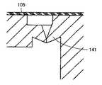
特許文献1に記載の薬液容器においては、図7に示すように、キャップ102の内側に設けられたフィルタ取付部材103の一方の面に疎水性フィルタ105を設け、他方の面に親水性フィルタ104を設けている。また疎水性フィルタ105と容器内部との間に流量制限部が設けられている。流量制限部は、逆止弁141、またはオリフィスで構成されている。 In the chemical container described in
特許文献1に記載の薬液容器によると、薬液がノズルから容器の内部に逆流するときには、親水性フィルタ104により細菌や微生物などの侵入が防止される。また、容器本体101に空気が流入するときには、疎水性フィルタ105により細菌や微生物などの侵入が防止される。加えて、疎水性フィルタ105と容器本体101の内部との間には、流量制限部としての逆止弁141またはオリフィスが設けられているので、ノズルの内部に滞留している薬液が親水性フィルタを通じて容器の内部に回収されるのに十分な時間、容器の内部を負圧に保つことができる。
特許文献1に記載の薬液容器ではダックビルタイプの逆止弁141が用いられている。この逆止弁141は、図8に示すように互いに連続する一対の楔状の弁体を成型した後、弁体の連続部にカッターなどを用いて切り込み加工する必要がある。逆止弁を所定の圧力で正確に動作させるためには、高度な切り込み加工精度が要求される。 In the chemical container described in
弁体はゴムやエラストマで構成されており、容易に変形するため正確に切断することは容易ではなかった。そのため製造誤差が避けられず、製品性能が安定しないという問題があった。 Since the valve body is made of rubber or elastomer and easily deforms, it has not been easy to cut accurately. For this reason, there is a problem that manufacturing errors are unavoidable and product performance is not stable.
また、特許文献1に記載の薬液容器において、流量制限部がオリフィスで構成されている場合には、内容液が疎水性フィルタ105に逆流し、疎水性フィルタ105の性能を損なうという問題があった。 Further, in the chemical solution container described in
加えて、特許文献1に記載の薬液容器においては、フィルタ取付部材の一方の面に疎水性フィルタを溶着し、他方の面に親水性フィルタを溶着し、さらに切り込み加工を行なう必要がある。すなわち、一つの部品を製造するために異なる方向から三つの工程を加える必要がある。 In addition, in the chemical solution container described in
薬液容器の内部構造を構成する小さい部品に対して、方向を転換しながら三つの工程を行なうことは、そのハンドリングが容易でない。また、この三つの工程のいずれか一つでも不良が発生すると、直接製品不良につながる上、最後の工程で不良が発生すると、前の全ての工程が無駄になるため影響が大きいという問題もある。 It is not easy to handle the small parts constituting the internal structure of the chemical solution container by performing the three steps while changing the direction. In addition, if any one of these three processes causes a defect, it directly leads to a product defect. If a defect occurs in the last process, all the previous processes are wasted, which has a large effect. .
この発明は、上記課題を解決するためになされたものであり、容器の内部への細菌等の侵入を防止した薬液容器において、製造が容易で薬液の逆流を確実に防止することができる逆止弁を備えた、薬液容器を提供することを目的とする。 The present invention has been made to solve the above-described problems, and is a non-return that is easy to manufacture and can reliably prevent backflow of a chemical solution in a chemical solution container that prevents bacteria and the like from entering the container. It aims at providing the chemical | medical solution container provided with the valve.
この発明に基づいた薬液容器に従えば、口部を有し、押圧により変形可能でかつ押圧を解除すると元の形状に復元する容器本体と、薬液を排出するための薬液排出路と空気を流入させるための空気導入路とが設けられ、上記容器本体の口部に取り付けられたキャップと、上記容器本体の内部に向かって突出する管体を有し、上記薬液排出路に親水性フィルタを介して連通する上記管体の内部の薬液導入路と上記空気導入路に連通する空気供給路とが設けられ、上記キャップの内側に配設された中間部材と、上記管体の外周面にその内周面が接触して上記容器本体の内部に向かう方向にのみ空気を通過させる逆止弁を構成する環状弁を有し、上記空気供給路にフィルタを介して連通すると共に容器本体内部に上記逆止弁を介して連通する空気送出路が設けられ、上記中間部材の内側に配設された中栓とを備えている。 According to the chemical container according to the present invention, the container body has a mouth, can be deformed by pressing, and is restored to the original shape when the pressing is released, and the chemical liquid discharge path for discharging the chemical liquid and the air flow in. An air introduction path for causing the container body to have a cap attached to the mouth of the container body and a tube projecting toward the inside of the container body, and a hydrophilic filter through the chemical solution discharge path. A chemical solution introduction path inside the pipe body communicating with the air supply path and an air supply path communicating with the air introduction path, an intermediate member disposed inside the cap, An annular valve that constitutes a check valve that allows air to pass only in a direction toward the inside of the container body when the peripheral surface comes into contact is communicated with the air supply path via a filter and the reverse of the inside of the container body Air feed communicating through a stop valve Road is provided, and a inner plug disposed inside said intermediate member.
上記薬液容器において、上記逆止弁は、上記容器本体の内部の圧力が、大気圧よりも5KPa以上低い時に、上記密封状態を解除し、上記空気送出路から上記容器本体の内部に向かう空気を通過させるものであってもよい。 In the chemical solution container, the check valve releases the sealed state when the pressure inside the container body is lower than the atmospheric pressure by 5 KPa or more, and allows air flowing from the air delivery path to the inside of the container body. It may be allowed to pass through.
上記薬液容器において、上記中栓の外周部は、上記容器本体の口部の端面と上記中間部材との間に挟持させるようにしてもよい。 In the chemical solution container, the outer peripheral portion of the inner plug may be sandwiched between the end face of the mouth of the container main body and the intermediate member.
上記薬液容器において、上記薬液排出路と上記薬液導入路との間に設けられた上記親水性フィルタは上記キャップに取り付けられ、上記空気供給路と上記空気送出路との間に設けられたフィルタは上記中間部材に取り付けられていてもよい。 In the chemical liquid container, the hydrophilic filter provided between the chemical liquid discharge path and the chemical liquid introduction path is attached to the cap, and the filter provided between the air supply path and the air delivery path is It may be attached to the intermediate member.
上記薬液容器において、上記空気供給路と上記空気送出路との間に設けられたフィルタは疎水性フィルタであってもよい。 In the chemical liquid container, the filter provided between the air supply path and the air delivery path may be a hydrophobic filter.
上記薬液容器において、上記中栓には、上記逆止弁と同軸上に位置し上記管体が嵌合される嵌合孔が設けてもよい。 In the chemical solution container, the inner plug may be provided with a fitting hole that is positioned coaxially with the check valve and into which the tubular body is fitted.
上記薬液容器において、上記嵌合孔の内面と上記管体の外面との間には、上記管体が貫通する方向に延びる通気溝が設けられていてもよい。 The said chemical | medical solution container WHEREIN: Between the inner surface of the said fitting hole and the outer surface of the said tubular body, the ventilation groove extended in the direction which the said tubular body penetrates may be provided.
本発明に係る薬液容器によると、製造が容易で薬液の逆流を確実に防止することができる逆止弁を備えた薬液容器を提供することができる。 According to the chemical solution container of the present invention, it is possible to provide a chemical solution container including a check valve that is easy to manufacture and can reliably prevent the back flow of the chemical solution.
以下、この発明に基づいた実施の形態における薬液容器の構造について、図を参照しながら説明する。 Hereinafter, the structure of a chemical solution container according to an embodiment based on the present invention will be described with reference to the drawings.
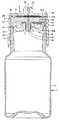
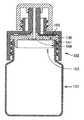
図1は、本実施の形態の薬液容器を示す分解斜視図であり、図2は同縦断面図である。図1および図2に示すように、本実施の形態の薬液容器は、容器本体1とキャップ2と中間部材3と中栓4とを備えている。容器本体1は、口部12を有し、押圧により変形可能でかつ押圧を解除すると元の形状に復元する。キャップ2は、薬液を排出するための薬液排出路25と空気を流入させるための空気導入路28とが設けられ、容器本体1の口部12に取り付けられている。中間部材3は、容器本体1の内部に向かって突出する管体35を有し、薬液排出路25に親水性フィルタ29を介して連通する管体35の内部の薬液導入路34と空気導入路28に連通する空気供給路36とが設けられ、キャップ2の内側に配設されている。中栓4は、管体35の外周面にその内周面が接触して容器本体1の内部に向かう方向にのみ空気を通過させる逆止弁を構成する環状弁42を有し、空気供給路36に疎水性フィルタ37を介して連通すると共に容器本体1内部に逆止弁を介して連通する空気送出路43が設けられ、中間部材3の内側に配設されている。以下、これらの各構造についてより詳しく説明する。 FIG. 1 is an exploded perspective view showing a chemical container of the present embodiment, and FIG. 2 is a longitudinal sectional view thereof. As shown in FIGS. 1 and 2, the chemical solution container of the present embodiment includes a
容器本体1は、図1に示すような有底円筒状、あるいは側壁の下端部を閉止したものなど、任意の形態を採用することができる。容器本体1の上端には胴部11よりも細径の口部12が設けられている。そして、口部12の外周面には、キャップ2を嵌合するための係合突起13が形成されている。係合突起13は、容器本体1の上端部の外周を周回するように設けられている。口部12の端面には、口部12の水密性を向上させるため円環状のリブが設けられている。このリブは組立後、中栓4に食い込んで口部12の水密性を向上させる。 The
容器本体1の材質は、手指での押圧により変形可能で、かつそのような押圧から開放されたときに、容易に元の形状に戻り得る可撓性材料が採用される。このような可撓性材料としては、例えばポリプロピレン、ポリエチレン、ポリエチレンテレフタレート、ポリエチレンテレナフタレート、ポリエステル、軟質ポリ塩化ビニル、熱可塑性エラストマ、ポリカーボネート等の弾性を有する各種高分子素材が挙げられる。 The material of the
キャップ2は、下面が開放した円筒状に形成された部材であって、円形の天板21と、その周縁から延びるスカート部22からなる。そして、スカート部22の内周面には、容器本体1の係合突起13と係合する被係合溝23が形成されている。 The
天板21の中心部分には上向きに突出するノズル24が設けられている。このノズル24は、円筒状あるいは円錐台形状に形成されている。ノズル24の内部には長軸方向に貫通したノズル孔により薬液排出路25が設けられている。薬液排出路25は、ノズル24の先端側に向かって内径が拡大している。また、キャップ2の外周面には雄ねじ部27が形成されている。 A
キャップ2の天板21には、これを上下に貫通するように空気導入路28が設けられている。本実施の形態では、空気導入路28をキャップ2の天板21の外周部の四箇所に等間隔に設けている。空気導入路28は、複数箇所設けることが好ましいが、1箇所であっても良い。 An
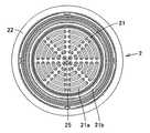
キャップ2の天板21の下面には、その外周部を溶着して親水性フィルタ29が設けられている。親水性フィルタ29は、円形に構成されている。 A
図3は、親水性フィルタを除いた状態のキャップの下面図である。親水性フィルタ29が接触する箇所には、同心円上に配置された多数のリブ21aが設けられている。リブ21aは、その中心から放射状に延びる線と交差する部分に、不連続部が設けられている。不連続部においては、リブ21aは設けられていない。 FIG. 3 is a bottom view of the cap with the hydrophilic filter removed. A large number of
このリブ21aは親水性フィルタ29と天板21の下面とが完全に密着することを防止するとともに流路を確保するものである。すなわち、不連続部およびリブ21a相互の隙間が流路となって、親水性フィルタ29の全面への流通を確保するものである。 The
空気導入路28は、平面視矩形に構成されている。また、その断面形状は、空気導入路28の内部を進むにしたがって断面積が狭くなるように構成されている。空気導入路28と親水性フィルタ29との間には両者を遮断する環状で下向きに突出した隔壁21bが設けられている。 The
図4は、中間部材の構造を示し、(a)は平面図、(b)は側面図、(c)は底面図である。中間部材3は、概ね円板状の中間部材本体31とその下面に下向きに突出した管体35とを有している。中間部材3の中心部には、それを上下方向に貫通する薬液導入路34が設けられている。薬液導入路34と、キャップ2に設けられた薬液排出路25とは、同一直線上に位置している。 4A and 4B show the structure of the intermediate member, where FIG. 4A is a plan view, FIG. 4B is a side view, and FIG. 4C is a bottom view. The
図1および図4(a)に示すように、中間部材本体31の上面の親水性フィルタ29と対向する箇所には、同心円上に配置された多数のリブ31aが設けられている。リブ31aには、その中心から放射状に延びる線と交差する部分に、不連続部が設けられている。不連続部においては、リブ31aは設けられていない。 As shown in FIG. 1 and FIG. 4A, a large number of
このリブ31aも、リブ21aと同様、親水性フィルタ29の全面への流路を確保するものである。リブ31aが設けられた箇所を囲むように隔壁31bが設けられている。図2に示すように、隔壁31bは、キャップ2の隔壁21bと密着して、空気導入路28と、親水性フィルタ29が設けられた薬液排出路25および薬液導入路34とを仕切る。 The
中間部材3の外周面は、下端部が上部および中間部よりも大径とされている。中間部材3の外周面の上部および中間部と、キャップ2の内周面との隙間により、図2に示すように空気供給路36の一部が形成される。中間部材本体31の内部には、中間部材3の外周面に開口し、水平方向に延びた後、下向きに折れ曲がった空気通路により空気供給路36の本体部分が形成されている。 As for the outer peripheral surface of the
空気供給路36を構成する空気通路の下流側端部が開口する箇所には、疎水性フィルタ37が設けられている。疎水性フィルタ37に代えて親水性フィルタを用いても良い。 A
疎水性フィルタ37は、円形に構成されており、その外周が溶着されて中間部材3の下面に取り付けられている。図4(c)は、疎水性フィルタを除去した状態の、中間部材の下面を示しているが、疎水性フィルタ37が設けられた箇所の中央部には、疎水性フィルタ37が中間部材3に密着することを防止する突起32が設けられている。疎水性フィルタ37は、中間部材3の中心からずれた位置に配置されている。 The
管体35の下部は円柱状に構成されている。中間部および上部は、下部より大径とされ、さらに、この大径の部分には縦に延びる通気溝35aが設けられている。管体35の下部は、環状弁42の内周面に密着し、通気溝35aは空気送出路43を構成する。 The lower part of the
キャップ2および中間部材3の材料としては、合成樹脂を用いることができる。キャップ2としては、ポリプロピレン、ポリエチレン、ポリエチレンテレフタレート、ポリカーボネートなどを用いることができる。中間部材3には、若干の弾力性および柔軟性が要求され、たとえば、ランダムポリプロピレン、ポリエチレン、エラストマ、塩化ビニルなどの材料を用いることができる。本実施の形態では、キャップ2をポリプロピレン、中間部材3をポリエチレンで構成している。 As a material for the
中栓4は、ゴムやエラストマなどの柔軟性に富む材料で構成されている。ここではスチレン系エラストマで構成している。中栓4を構成する材料としては、例えば熱可塑性エラストマやポリオレフィン系樹脂(低密度ポリエチレン、ランダムポリプロピレン)が挙げられる。中栓4の上面には、円形の窪み41が設けられている。この窪み41は、疎水性フィルタ37に対向している。窪み41は、疎水性フィルタ37を経由して流入した空気の流路となる。 The
中栓4の中央部には縦方向に管体35が貫通する貫通孔44が設けられている。貫通孔44の下端部には、環状弁42が設けられている。環状弁42は、図1および図2に示すように、下方向に進むにしたがって肉厚が薄く形成された、環状の部材であり、管体35の外周にその下端部の内周面が密着することで逆止弁を構成する。 A through
中栓4の上端部には外周部が外側に突出したフランジ部45が設けられている。フランジ部45の下面は、容器本体1の口部12の端面に密着する。組み立てた状態において中栓4の外周のフランジ部45は、容器本体1の口部12の端面と中間部材3との間に挟持される。この中栓4の弾性により、キャップ2と中間部材3、中間部材3と中栓4、中栓4と容器本体1の間が密着し、気密性を保つことができる。 A
ノズル24の先端を塞ぐため、図1に示すような、ノズルキャップ6が設けられる。ノズルキャップ6は、底部が開口した略円筒状の部材であり、その天井面には、ノズル24の先端部に密着しノズル孔を気密に密閉する封止部61が設けられている。 In order to close the tip of the
この封止部61は、下面が開放した円筒状に形成されている。ノズルキャップ6は、その内周面に雌ねじ部62が設けられている。ノズルキャップ6は、キャップ2の外周面に設けられた雄ねじ部27と、その雌ねじ部62とが螺合することで固定される。ノズルキャップ6は、ノズル24と空気導入路28の両方を封止する。 The sealing
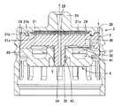
図5は、キャップ、中間部材および中栓の構造を示す分解断面図であり、図6は、キャップ、中間部材および中栓を組み立てた状態の断面図である。本実施の形態の薬液容器を組み立てるときには、キャップ2の内部に、中間部材3および中栓4を挿入する。その後、容器本体1の口部12をキャップ2の内部に挿入することで、キャップ2、中間部材3、中栓4および口部12を相互に密着させる。 FIG. 5 is an exploded cross-sectional view showing the structure of the cap, the intermediate member, and the inner plug, and FIG. 6 is a cross-sectional view of the cap, the intermediate member, and the inner plug assembled. When assembling the chemical solution container of the present embodiment, the
このとき、中間部材3の管体35は、中栓4の貫通孔44を貫通する。管体35の上部および中間部は、上述のとおり、下部よりも大径とされている。管体35の大径の部分が、中栓4の貫通孔44に嵌合される。これにより、管体35は、中栓4の所定位置に位置決めされる。同時に管体35の先端の小径部が、中栓4の環状弁42の内周面に密着し逆止弁が形成される。このとき管体35と中栓4とが正確に位置決めされているので、環状弁42に対して管体35を所定の位置に確実に位置させることができ、所望の性能の逆止弁を確実に得ることができる。 At this time, the
また、逆止弁は、環状弁42の内部に管体35を貫通させるだけで構成することができるので、従来の逆止弁のように切り込み加工などをする必要がなく容易かつ確実に動作する逆止弁を構成することができる。 Further, since the check valve can be configured only by passing the
本実施の形態の逆止弁は、容器本体1の内部の圧力が、大気圧よりも5KPa以上低い時に、環状弁42が外側に開くことで管体35との間に隙間が生じて密封状態を解除し、空気送出路43から容器本体1の内部に向かう空気を通過させるように構成している。これは、指で押圧して変形した容器本体1が、元の形状に戻ろうとする力により容器本体1の内部に発生する負圧力が5KPaから30KPaであることに基づく。 In the check valve of the present embodiment, when the pressure inside the
本来、逆止弁は、容器本体1の内部に少しでも負圧力が発生すれば、空気送出路43からの空気を流入させ、空気送出路43への逆流を発生させないものであればよい。しかし、逆流を確実に防止する観点、および、逆止弁の流量制限部材としての観点から、容器本体1により発生する負圧力よりも少し小さい程度の負圧力で開放する逆止弁を用いることが好ましい。変形した状態から元の形状に戻る際に、容器本体1の内部に発生する負圧力が、大きい場合には、逆止弁が開放する圧力を大きくしてもよい。逆止弁が開放する圧力は環状弁の材質、形状などを変更することにより、種々の値に設定することができる。 Essentially, the check valve may be any valve that does not cause a backflow to the
本実施の形態の薬液容器の使用方法について説明する。まず使用時にはノズルキャップ6を取り外す。ついで、薬液を排出すべく容器本体1を手指で圧迫する。内部の薬液は、容器の内部から押し出され、薬液導入路34、親水性フィルタ29および薬液排出路25を通過して、ノズル24から外部に滴下される。 The usage method of the chemical | medical solution container of this Embodiment is demonstrated. First, the nozzle cap 6 is removed during use. Next, the
このとき、環状弁42と管体35とからなる逆止弁は閉じているので、薬液が空気送出路43に進入することはない。したがって、疎水性フィルタ37に薬液が触れることもない。そのため、疎水性フィルタ37の材質と相性の悪い薬液を用いる場合であっても、疎水性フィルタ37の劣化(例えば、親水性化など)を防止でき、疎水性フィルタ37の下面での薬液の結晶析出を防止することができる。At this time, since the check valve including the
そして、必要量滴下した後、容器本体1の圧迫をやめると、容器本体1はその可撓性に基づき元の形状に戻るように膨らむ。このとき容器本体1内は負圧になる。この負圧によってノズル孔の内部に排出停止後に溜まっていた薬液は、親水性フィルタ29を通過して、容器本体1内に戻されることになる。 Then, after the required amount is dropped, when the compression of the
ノズル孔の内部に溜まっていた薬液は親水性フィルタ29を経由して容器本体1の内部に戻るので、ノズル孔の内部に溜まっていた薬液に細菌等が混入していても、親水性フィルタ29でろ過される。 Since the chemical solution accumulated in the nozzle hole returns to the inside of the container
一方、容器本体1の内部が負圧になるので逆止弁は若干開く。これにより、空気導入路28、空気供給路36、疎水性フィルタ37および空気送出路43を経由して容器本体1の内部に空気が流入する。このとき、逆止弁により空気の流量が制限されるので、空気は容器本体1の内部に少しずつ進入し、容器本体1の元の形状への復帰も時間をかけてゆっくりと行われる。すなわち、親水性フィルタ29上の薬液が容器本体1内に回収される十分な時間を確保することができる。 On the other hand, since the inside of the container
このように、容器本体1内の負圧により薬液が親水性フィルタ29を通過する時間が充分確保されることから、ノズル24内に薬液の残りが溜まることを回避することができる。ノズル24の内部に薬液が長期間残留すると、その残留した薬液中で雑菌等が繁殖し、次に使用するときにこれが薬液中に混入することがあるが、本実施の形態の薬液容器によるとこのような不具合を回避することができる。 As described above, a sufficient time for the chemical liquid to pass through the
また、容器本体1の内部に流入する空気は、疎水性フィルタ37を経由することで細菌や微生物などがろ過される。これらにより容器本体1の内部を無菌状態に保つことができる。 In addition, the air flowing into the
このような親水性フィルタおよび疎水性フィルタの孔径は、汚染起因菌として通常知られているCandida albicans、Pseudomonas属、Burkholderia cepaciaらの容器内部への侵入を防ぐために、好ましくは0.45μm以下、より好ましくは0.22μm以下であることが望ましい。 The pore size of such a hydrophilic filter and a hydrophobic filter is preferably 0.45 μm or less in order to prevent invasion of Candida albicans, Pseudomonas genus, Burkholderia cepacia et al. Preferably it is 0.22 μm or less.
また、フィルタの捕捉機構は、フィルタ内部で捕捉する「デプスタイプ」と、フィルタ表面で捕捉する「スクリーンタイプ」の2種類に大別されるが、本発明ではいずれのタイプも好適に用いることができる。 In addition, filter capture mechanisms are roughly classified into two types: “depth type” that captures inside the filter and “screen type” that captures on the filter surface. In the present invention, any type is preferably used. it can.
本実施の形態の薬液容器においては、キャップ2に親水性フィルタ29を取り付け、中間部材3に疎水性フィルタ37を取り付けている。二つのフィルタを一つの部材には取り付けず、異なる部材にそれぞれ取り付けたので、フィルタの取り付け作業においては、一つの部材の両面にそれぞれ疎水性フィルタと親水性フィルタとを取り付けた従来の薬液容器のように、部材を反転させる必要がなく、その作業を容易に行なうことができる。 In the chemical container of the present embodiment, the
本発明に係る薬液容器は、化粧品よりも高い無菌性の要求される薬品において、さらに薬品の中にあっても、保存剤の添加が制限される点眼剤を保存する点眼容器に使用する場合においてその効果は顕著である。 The drug solution container according to the present invention is used in an eye drop container for storing an eye drop in which the addition of a preservative is restricted even in a drug requiring a higher sterility than cosmetics. The effect is remarkable.
なお、今回開示した上記実施の形態はすべての点で例示であって、限定的な解釈の根拠となるものではない。したがって、本発明の技術的範囲は、上記した実施の形態のみによって解釈されるのではなく、特許請求の範囲の記載に基づいて画定される。また、特許請求の範囲と均等の意味および範囲内でのすべての変更が含まれる。 In addition, the said embodiment disclosed this time is an illustration in all the points, Comprising: It does not become the basis of limited interpretation. Therefore, the technical scope of the present invention is not interpreted only by the above-described embodiments, but is defined based on the description of the claims. Further, all modifications within the meaning and scope equivalent to the scope of the claims are included.
1 容器本体、2 キャップ、3 中間部材、4 中栓、6 ノズルキャップ、11 胴部、12 口部、13 係合突起、21 天板、21a リブ、21b 隔壁、22 スカート部、23 被係合溝、24 ノズル、25 薬液排出路、27 雄ねじ部、28 空気導入路、29 親水性フィルタ、31 中間部材本体、31a リブ、31b 隔壁、32 突起、34 薬液導入路、35 管体、35a 通気溝、36 空気供給路、37 疎水性フィルタ、42 環状弁、43 空気送出路、44 貫通孔、45 フランジ部、61 封止部、62 雌ねじ部。DESCRIPTION OF
Claims (7)
Translated fromJapanese薬液を排出するための薬液排出路と空気を流入させるための空気導入路とが設けられ、前記容器本体の口部に取り付けられたキャップと、
前記容器本体の内部に向かって突出する管体を有し、前記薬液排出路に親水性フィルタを介して連通する前記管体の内部の薬液導入路と前記空気導入路に連通する空気供給路とが設けられ、前記キャップの内側に配設された中間部材と、
前記管体の外周面にその内周面が接触して前記容器本体の内部に向かう方向にのみ空気を通過させる逆止弁を構成する環状弁を有し、前記空気供給路にフィルタを介して連通すると共に容器本体内部に前記逆止弁を介して連通する空気送出路が設けられ、前記中間部材の内側に配設された中栓と、を備えた、薬液容器。A container body that has a mouth, is deformable by pressing, and restores its original shape when the pressing is released;
A chemical solution discharge path for discharging the chemical liquid and an air introduction path for allowing air to flow in, a cap attached to the mouth of the container body;
A tube projecting toward the inside of the container main body, and a chemical solution introduction path inside the tube that communicates with the chemical solution discharge path via a hydrophilic filter; and an air supply path that communicates with the air introduction path; An intermediate member disposed inside the cap;
An annular valve that constitutes a check valve that allows the air to pass only in the direction toward the inside of the container main body with the inner peripheral surface coming into contact with the outer peripheral surface of the tube body, and through the filter in the air supply path A chemical solution container, comprising: an air delivery path that communicates with the interior of the container body via the check valve, and an inner plug disposed inside the intermediate member.
Priority Applications (9)
| Application Number | Priority Date | Filing Date | Title |
|---|---|---|---|
| JP2006318718AJP4869039B2 (en) | 2006-11-27 | 2006-11-27 | Chemical container |
| HK10100777.7AHK1137136B (en) | 2006-11-27 | 2007-11-13 | Chemical liquid container |
| PCT/JP2007/071982WO2008065879A1 (en) | 2006-11-27 | 2007-11-13 | Chemical liquid container |
| EP07831712AEP2090277B1 (en) | 2006-11-27 | 2007-11-13 | Liquid agent container |
| US12/516,322US9308150B2 (en) | 2006-11-27 | 2007-11-13 | Liquid agent container |
| CN2007800439318ACN101541292B (en) | 2006-11-27 | 2007-11-13 | Chemical liquid container |
| KR1020097012544AKR101387773B1 (en) | 2006-11-27 | 2007-11-13 | Chemical liquid container |
| AT07831712TATE508724T1 (en) | 2006-11-27 | 2007-11-13 | CONTAINER FOR CHEMICAL LIQUIDS |
| ES07831712TES2365767T3 (en) | 2006-11-27 | 2007-11-13 | CONTAINER FOR LIQUID AGENTS. |
Applications Claiming Priority (1)
| Application Number | Priority Date | Filing Date | Title |
|---|---|---|---|
| JP2006318718AJP4869039B2 (en) | 2006-11-27 | 2006-11-27 | Chemical container |
Publications (3)
| Publication Number | Publication Date |
|---|---|
| JP2008132013A JP2008132013A (en) | 2008-06-12 |
| JP2008132013A5 JP2008132013A5 (en) | 2009-12-24 |
| JP4869039B2true JP4869039B2 (en) | 2012-02-01 |
Family
ID=39467674
Family Applications (1)
| Application Number | Title | Priority Date | Filing Date |
|---|---|---|---|
| JP2006318718AActiveJP4869039B2 (en) | 2006-11-27 | 2006-11-27 | Chemical container |
Country Status (8)
| Country | Link |
|---|---|
| US (1) | US9308150B2 (en) |
| EP (1) | EP2090277B1 (en) |
| JP (1) | JP4869039B2 (en) |
| KR (1) | KR101387773B1 (en) |
| CN (1) | CN101541292B (en) |
| AT (1) | ATE508724T1 (en) |
| ES (1) | ES2365767T3 (en) |
| WO (1) | WO2008065879A1 (en) |
Families Citing this family (41)
| Publication number | Priority date | Publication date | Assignee | Title |
|---|---|---|---|---|
| US7547300B2 (en) | 2006-04-12 | 2009-06-16 | Icu Medical, Inc. | Vial adaptor for regulating pressure |
| JP4869039B2 (en)* | 2006-11-27 | 2012-02-01 | ニプロ株式会社 | Chemical container |
| WO2010081081A2 (en)* | 2009-01-09 | 2010-07-15 | Porex Corporation | Relief vent for a hot fill fluid container |
| JP5277047B2 (en)* | 2009-03-31 | 2013-08-28 | 本田技研工業株式会社 | Variable valve gear for engine |
| WO2011094578A1 (en)* | 2010-01-29 | 2011-08-04 | Graham Packaging Company, L.P. | Pressure equalizing closure |
| EP2361599A1 (en)* | 2010-02-22 | 2011-08-31 | Fresenius Kabi Deutschland GmbH | Device for supplying or removing a liquid into or out of a container |
| JP5937090B2 (en)* | 2010-10-12 | 2016-06-22 | ナルジェ・エヌユーエヌシー・インターナショナル・コーポレーション | Ventable closure with port |
| KR101221314B1 (en)* | 2010-10-19 | 2013-01-10 | 김준배 | Liquid droplets containers |
| US8991643B2 (en) | 2011-03-29 | 2015-03-31 | Graham Packaging Company, L.P. | Closure for use in hotfill and pasteurization applications |
| CN202022423U (en)* | 2011-04-07 | 2011-11-02 | 杜斌 | Container with anti-leakage one-way valve |
| CA3176437A1 (en) | 2011-08-18 | 2013-02-21 | Icu Medical, Inc. | Pressure-regulating vial adaptors |
| KR101319927B1 (en)* | 2011-12-01 | 2013-10-18 | 윤희권 | Container unit for feeding of liquid food |
| AU2013204180B2 (en) | 2012-03-22 | 2016-07-21 | Icu Medical, Inc. | Pressure-regulating vial adaptors |
| HK1212203A1 (en)* | 2012-12-21 | 2016-06-10 | 费森尤斯卡比德国有限公司 | Milk bottle adapter |
| EP2786802A1 (en)* | 2013-04-03 | 2014-10-08 | Metrohm Ag | Lock for a container |
| KR200470695Y1 (en)* | 2013-08-14 | 2014-01-15 | 박국서 | pumping container for air blocking |
| WO2015195844A1 (en)* | 2014-06-20 | 2015-12-23 | Icu Medical, Inc. | Pressure-regulating vial adaptors |
| US10857067B2 (en)* | 2015-03-31 | 2020-12-08 | Laboratories Thea | Device for dispensing liquid from a sterile packaging bottle with bi-functional membrane |
| JP6611564B2 (en)* | 2015-10-30 | 2019-11-27 | キヤノン株式会社 | Liquid storage bottle and liquid storage bottle package |
| WO2017099235A1 (en)* | 2015-12-10 | 2017-06-15 | 小林製薬株式会社 | Chemical solution supply apparatus and chemical solution supply implement |
| CN105712267B (en)* | 2016-04-14 | 2018-04-06 | 王景东 | It is a kind of to seal and apply its liquid containing container |
| CN106492550A (en)* | 2016-12-20 | 2017-03-15 | 广东顺德工业设计研究院(广东顺德创新设计研究院) | Chemical detection system |
| CN106475162A (en)* | 2016-12-20 | 2017-03-08 | 广东顺德工业设计研究院(广东顺德创新设计研究院) | Solution delivery safety lid and reagent bottle |
| US10238579B2 (en)* | 2017-02-24 | 2019-03-26 | Compliance Meds Technologies Llc | Customizable modular cap system for use with a plurality of different sized bottles |
| WO2019031665A1 (en) | 2017-08-11 | 2019-02-14 | 주식회사 엘지생활건강 | Cosmetic container |
| US20200410444A1 (en)* | 2018-03-01 | 2020-12-31 | 3M Innovative Properties Company | Personal protection equipment identification system |
| FR3080844B1 (en)* | 2018-05-07 | 2020-06-05 | Horus Pharma | PACKAGING AND DISPENSING DEVICE OF A PRODUCT WITH BOTTLE AND METERING CAP WITH FILTER |
| CN108685688B (en)* | 2018-06-12 | 2024-05-17 | 张家港众辉医用塑料科技有限公司 | Three-stage filtration aseptic liquid medicine package |
| KR101966382B1 (en)* | 2018-08-17 | 2019-04-08 | 박국서 | Pumping container manufacturing method |
| JP7293701B2 (en)* | 2019-02-08 | 2023-06-20 | 株式会社デンソー | Rotating electric machine |
| EP4414287A1 (en) | 2019-03-01 | 2024-08-14 | Berry Global, Inc. | Pediatric dosing dispenser |
| US11452672B2 (en)* | 2019-03-01 | 2022-09-27 | Berry Global, Inc. | Pediatric dosing dispenser |
| WO2020190490A1 (en) | 2019-03-15 | 2020-09-24 | Berry Global, Inc. | Pediatric dosing dispenser |
| CN110200807B (en)* | 2019-07-06 | 2022-02-01 | 中国人民解放军海军第九七一医院 | Liquid leakage prevention medicine bottle |
| BR202020001057U2 (en)* | 2020-01-17 | 2021-07-27 | Alvaro Augusto Fernandes Filho | ADAPTABLE COVER FOR BOTTLE NOZZLES, WITH FLUID DIRECTING ELEMENT THROUGH A GASIFICATION DEVICE, FOR THE CARBONATION OF LIQUIDS |
| CN220403706U (en)* | 2020-02-07 | 2024-01-30 | Bivo有限责任公司 | Sports drink bottle components |
| EP4396103A4 (en) | 2021-09-01 | 2025-07-02 | Berry Global Inc | PEDIATRIC DOSING DISPENSER |
| KR102663933B1 (en)* | 2021-12-10 | 2024-05-03 | 서울대학교 산학협력단 | Vial having vent function |
| US11873146B1 (en)* | 2022-07-21 | 2024-01-16 | Jose Gonzalez | Child safety device for medication dispenser |
| WO2025147199A1 (en)* | 2024-01-04 | 2025-07-10 | Gamboa Burgos Alejandro | Liquid dispenser with a tip opening mechanism of the type without preservatives for blow-fill-seal containers |
| KR102828618B1 (en)* | 2024-10-28 | 2025-07-02 | 유니메드제약주식회사 | Multi-use medication liquid drop container having airflow plate module with air filter, and manufacturing method thereof |
Family Cites Families (19)
| Publication number | Priority date | Publication date | Assignee | Title |
|---|---|---|---|---|
| US4513891A (en)* | 1982-04-15 | 1985-04-30 | Sterling Drug Inc. | Spray dispensing container and valve therefor |
| US4736083A (en)* | 1985-02-19 | 1988-04-05 | Savillex Corporation | Microwave heating digestion vessel |
| JPS62127063A (en) | 1985-11-27 | 1987-06-09 | ト−メ−産業株式会社 | eye drop container |
| US5320254A (en)* | 1988-10-07 | 1994-06-14 | Ryder International Corp. | Liquid dispenser nozzle assembly |
| DE4015480A1 (en)* | 1990-05-14 | 1991-11-21 | Perfect Ventil Gmbh | CAP |
| EP0812625A3 (en)* | 1992-11-11 | 1998-01-14 | Tee Enterprises Limited | A carrier for a pump type atomiser |
| EP0631770B1 (en)* | 1993-06-25 | 1998-07-22 | Alcon Cusi, S.A. | New use of polymeric membranes in the dispensing of pharmaceutical solutions that contain quaternary ammonium compounds as preservatives and corresponding dose dispensor |
| US5490938A (en)* | 1993-12-20 | 1996-02-13 | Biopolymerix, Inc. | Liquid dispenser for sterile solutions |
| GB9717595D0 (en)* | 1997-08-21 | 1997-10-22 | Metal Box Plc | Valves for packaging containers |
| US5988448A (en)* | 1997-09-18 | 1999-11-23 | Foth; Gary S. | Vacuum release container cap |
| JP4580524B2 (en)* | 2000-09-12 | 2010-11-17 | 株式会社日本点眼薬研究所 | Discharge container with filter |
| US6631823B2 (en)* | 2001-03-05 | 2003-10-14 | Acorn Bay, Llc | Drink spout system |
| JP4749572B2 (en)* | 2001-03-13 | 2011-08-17 | 大成化工株式会社 | Dispensing container plug structure |
| JP4744775B2 (en)* | 2002-11-20 | 2011-08-10 | ニプロ株式会社 | Chemical container |
| EP1495747B1 (en)* | 2002-04-04 | 2013-01-16 | Nipro Corporation | Liquid drug container |
| CN101589939B (en)* | 2002-09-09 | 2011-08-03 | 宝洁公司 | Fluid delivery mechanism |
| EP1631496B1 (en)* | 2003-04-28 | 2014-02-26 | Medical Instill Technologies, Inc. | Container with valve assembly for filling and dispensing substances, and apparatus and method for filling |
| US6874656B2 (en)* | 2003-06-04 | 2005-04-05 | Rieke Corporation | Vented closure |
| JP4869039B2 (en)* | 2006-11-27 | 2012-02-01 | ニプロ株式会社 | Chemical container |
- 2006
- 2006-11-27JPJP2006318718Apatent/JP4869039B2/enactiveActive
- 2007
- 2007-11-13WOPCT/JP2007/071982patent/WO2008065879A1/enactiveApplication Filing
- 2007-11-13ATAT07831712Tpatent/ATE508724T1/ennot_activeIP Right Cessation
- 2007-11-13USUS12/516,322patent/US9308150B2/enactiveActive
- 2007-11-13EPEP07831712Apatent/EP2090277B1/enactiveActive
- 2007-11-13KRKR1020097012544Apatent/KR101387773B1/enactiveActive
- 2007-11-13CNCN2007800439318Apatent/CN101541292B/enactiveActive
- 2007-11-13ESES07831712Tpatent/ES2365767T3/enactiveActive
Also Published As
| Publication number | Publication date |
|---|---|
| EP2090277B1 (en) | 2011-05-11 |
| US9308150B2 (en) | 2016-04-12 |
| JP2008132013A (en) | 2008-06-12 |
| ES2365767T3 (en) | 2011-10-10 |
| EP2090277A4 (en) | 2010-03-10 |
| ATE508724T1 (en) | 2011-05-15 |
| US20100084397A1 (en) | 2010-04-08 |
| WO2008065879A1 (en) | 2008-06-05 |
| CN101541292A (en) | 2009-09-23 |
| HK1137136A1 (en) | 2010-07-23 |
| EP2090277A1 (en) | 2009-08-19 |
| CN101541292B (en) | 2012-10-03 |
| KR20090086256A (en) | 2009-08-11 |
| KR101387773B1 (en) | 2014-04-21 |
Similar Documents
| Publication | Publication Date | Title |
|---|---|---|
| JP4869039B2 (en) | Chemical container | |
| KR100660676B1 (en) | Chemical container | |
| EP3107618B1 (en) | Connector with filter | |
| JP5215632B2 (en) | Connector priming method | |
| US8540691B2 (en) | Drug solution transferring device | |
| AU2004270543A1 (en) | Discharge member, discharge container having the discharge member, and instillation container | |
| US20110144598A1 (en) | Filtering dispenser container | |
| JP2006521887A (en) | Multiple dose liquid dispensing assembly | |
| JP4744775B2 (en) | Chemical container | |
| WO2003095325A1 (en) | Contamination preventive cap | |
| JP4357159B2 (en) | Chemical container | |
| JP4047617B2 (en) | Chemical container | |
| JP4255341B2 (en) | Anti-contamination cap | |
| US11529288B2 (en) | Integrated cap and seal system | |
| HK1137136B (en) | Chemical liquid container | |
| JP4161338B2 (en) | Dripping container | |
| KR20230149999A (en) | Liquid chemical container | |
| WO2004039305A1 (en) | Contamination preventing cap | |
| JP2004168423A (en) | Pollution preventive cap | |
| HK1070266B (en) | Liquid drug container |
Legal Events
| Date | Code | Title | Description |
|---|---|---|---|
| A521 | Request for written amendment filed | Free format text:JAPANESE INTERMEDIATE CODE: A523 Effective date:20091110 | |
| A621 | Written request for application examination | Free format text:JAPANESE INTERMEDIATE CODE: A621 Effective date:20091110 | |
| TRDD | Decision of grant or rejection written | ||
| A01 | Written decision to grant a patent or to grant a registration (utility model) | Free format text:JAPANESE INTERMEDIATE CODE: A01 Effective date:20111101 | |
| A01 | Written decision to grant a patent or to grant a registration (utility model) | Free format text:JAPANESE INTERMEDIATE CODE: A01 | |
| A61 | First payment of annual fees (during grant procedure) | Free format text:JAPANESE INTERMEDIATE CODE: A61 Effective date:20111115 | |
| R150 | Certificate of patent or registration of utility model | Ref document number:4869039 Country of ref document:JP Free format text:JAPANESE INTERMEDIATE CODE: R150 Free format text:JAPANESE INTERMEDIATE CODE: R150 | |
| FPAY | Renewal fee payment (event date is renewal date of database) | Free format text:PAYMENT UNTIL: 20141125 Year of fee payment:3 | |
| S531 | Written request for registration of change of domicile | Free format text:JAPANESE INTERMEDIATE CODE: R313531 | |
| R350 | Written notification of registration of transfer | Free format text:JAPANESE INTERMEDIATE CODE: R350 | |
| R250 | Receipt of annual fees | Free format text:JAPANESE INTERMEDIATE CODE: R250 | |
| R250 | Receipt of annual fees | Free format text:JAPANESE INTERMEDIATE CODE: R250 | |
| R250 | Receipt of annual fees | Free format text:JAPANESE INTERMEDIATE CODE: R250 | |
| R250 | Receipt of annual fees | Free format text:JAPANESE INTERMEDIATE CODE: R250 | |
| R250 | Receipt of annual fees | Free format text:JAPANESE INTERMEDIATE CODE: R250 | |
| R250 | Receipt of annual fees | Free format text:JAPANESE INTERMEDIATE CODE: R250 | |
| R250 | Receipt of annual fees | Free format text:JAPANESE INTERMEDIATE CODE: R250 | |
| R250 | Receipt of annual fees | Free format text:JAPANESE INTERMEDIATE CODE: R250 | |
| R250 | Receipt of annual fees | Free format text:JAPANESE INTERMEDIATE CODE: R250 |