JP4868602B2 - Surgical hand access device - Google Patents
Surgical hand access deviceDownload PDFInfo
- Publication number
- JP4868602B2 JP4868602B2JP2007506367AJP2007506367AJP4868602B2JP 4868602 B2JP4868602 B2JP 4868602B2JP 2007506367 AJP2007506367 AJP 2007506367AJP 2007506367 AJP2007506367 AJP 2007506367AJP 4868602 B2JP4868602 B2JP 4868602B2
- Authority
- JP
- Japan
- Prior art keywords
- surgical access
- tensioning
- liner
- access device
- seal
- Prior art date
- Legal status (The legal status is an assumption and is not a legal conclusion. Google has not performed a legal analysis and makes no representation as to the accuracy of the status listed.)
- Expired - Fee Related
Links
- 239000012530fluidSubstances0.000claimsdescription14
- 238000003780insertionMethods0.000claimsdescription12
- 230000037431insertionEffects0.000claimsdescription12
- 230000000694effectsEffects0.000claimsdescription5
- 230000007246mechanismEffects0.000claimsdescription4
- 238000013459approachMethods0.000claimsdescription3
- 238000000034methodMethods0.000description19
- 239000013013elastic materialSubstances0.000description8
- 238000001356surgical procedureMethods0.000description8
- 230000002093peripheral effectEffects0.000description7
- 239000000463materialSubstances0.000description5
- 210000000683abdominal cavityAnatomy0.000description4
- 238000010586diagramMethods0.000description3
- 238000012830laparoscopic surgical procedureMethods0.000description3
- 230000009471actionEffects0.000description2
- 230000000712assemblyEffects0.000description2
- 238000000429assemblyMethods0.000description2
- 230000008901benefitEffects0.000description2
- 238000010276constructionMethods0.000description2
- 230000008878couplingEffects0.000description2
- 238000010168coupling processMethods0.000description2
- 238000005859coupling reactionMethods0.000description2
- 238000012976endoscopic surgical procedureMethods0.000description2
- 239000004744fabricSubstances0.000description2
- 208000015181infectious diseaseDiseases0.000description2
- 208000014674injuryDiseases0.000description2
- 230000000968intestinal effectEffects0.000description2
- 238000002357laparoscopic surgeryMethods0.000description2
- 238000012978minimally invasive surgical procedureMethods0.000description2
- 238000012986modificationMethods0.000description2
- 230000004048modificationEffects0.000description2
- -1polyethylenePolymers0.000description2
- 238000011084recoveryMethods0.000description2
- 230000008733traumaEffects0.000description2
- JOYRKODLDBILNP-UHFFFAOYSA-NEthyl urethaneChemical compoundCCOC(N)=OJOYRKODLDBILNP-UHFFFAOYSA-N0.000description1
- 241000405070PercophidaeSpecies0.000description1
- 239000004698PolyethyleneSubstances0.000description1
- 239000004743PolypropyleneSubstances0.000description1
- 229910001069Ti alloyInorganic materials0.000description1
- RTAQQCXQSZGOHL-UHFFFAOYSA-NTitaniumChemical compound[Ti]RTAQQCXQSZGOHL-UHFFFAOYSA-N0.000description1
- 230000003187abdominal effectEffects0.000description1
- 210000003815abdominal wallAnatomy0.000description1
- 239000000853adhesiveSubstances0.000description1
- 230000001070adhesive effectEffects0.000description1
- 239000011248coating agentSubstances0.000description1
- 238000000576coating methodMethods0.000description1
- 238000011109contaminationMethods0.000description1
- 238000006073displacement reactionMethods0.000description1
- 239000006260foamSubstances0.000description1
- 210000001035gastrointestinal tractAnatomy0.000description1
- 238000010348incorporationMethods0.000description1
- 238000001746injection mouldingMethods0.000description1
- 210000000936intestineAnatomy0.000description1
- 239000007769metal materialSubstances0.000description1
- 238000002324minimally invasive surgeryMethods0.000description1
- 210000000056organAnatomy0.000description1
- 239000004033plasticSubstances0.000description1
- 229920003023plasticPolymers0.000description1
- 239000004417polycarbonateSubstances0.000description1
- 229920000515polycarbonatePolymers0.000description1
- 229920000573polyethylenePolymers0.000description1
- 229920001195polyisoprenePolymers0.000description1
- 239000002861polymer materialSubstances0.000description1
- 229920001155polypropylenePolymers0.000description1
- 229920001296polysiloxanePolymers0.000description1
- 239000010935stainless steelSubstances0.000description1
- 229910001220stainless steelInorganic materials0.000description1
- 229910052719titaniumInorganic materials0.000description1
- 239000010936titaniumSubstances0.000description1
- 238000012800visualizationMethods0.000description1
- 238000004804windingMethods0.000description1
Images


Classifications
- A—HUMAN NECESSITIES
- A61—MEDICAL OR VETERINARY SCIENCE; HYGIENE
- A61B—DIAGNOSIS; SURGERY; IDENTIFICATION
- A61B1/00—Instruments for performing medical examinations of the interior of cavities or tubes of the body by visual or photographical inspection, e.g. endoscopes; Illuminating arrangements therefor
- A61B1/313—Instruments for performing medical examinations of the interior of cavities or tubes of the body by visual or photographical inspection, e.g. endoscopes; Illuminating arrangements therefor for introducing through surgical openings, e.g. laparoscopes
- A—HUMAN NECESSITIES
- A61—MEDICAL OR VETERINARY SCIENCE; HYGIENE
- A61B—DIAGNOSIS; SURGERY; IDENTIFICATION
- A61B17/00—Surgical instruments, devices or methods
- A61B17/34—Trocars; Puncturing needles
- A61B17/3417—Details of tips or shafts, e.g. grooves, expandable, bendable; Multiple coaxial sliding cannulas, e.g. for dilating
- A61B17/3421—Cannulas
- A61B17/3423—Access ports, e.g. toroid shape introducers for instruments or hands
- A—HUMAN NECESSITIES
- A61—MEDICAL OR VETERINARY SCIENCE; HYGIENE
- A61B—DIAGNOSIS; SURGERY; IDENTIFICATION
- A61B17/00—Surgical instruments, devices or methods
- A61B17/34—Trocars; Puncturing needles
- A61B17/3462—Trocars; Puncturing needles with means for changing the diameter or the orientation of the entrance port of the cannula, e.g. for use with different-sized instruments, reduction ports, adapter seals
- A—HUMAN NECESSITIES
- A61—MEDICAL OR VETERINARY SCIENCE; HYGIENE
- A61B—DIAGNOSIS; SURGERY; IDENTIFICATION
- A61B17/00—Surgical instruments, devices or methods
- A61B17/34—Trocars; Puncturing needles
- A61B17/3498—Valves therefor, e.g. flapper valves, slide valves
- A—HUMAN NECESSITIES
- A61—MEDICAL OR VETERINARY SCIENCE; HYGIENE
- A61B—DIAGNOSIS; SURGERY; IDENTIFICATION
- A61B17/00—Surgical instruments, devices or methods
- A61B17/00234—Surgical instruments, devices or methods for minimally invasive surgery
- A61B2017/00238—Type of minimally invasive operation
- A61B2017/00265—Hand assisted surgery, i.e. minimally invasive surgery with at least part of an assisting hand inside the body
- A—HUMAN NECESSITIES
- A61—MEDICAL OR VETERINARY SCIENCE; HYGIENE
- A61B—DIAGNOSIS; SURGERY; IDENTIFICATION
- A61B17/00—Surgical instruments, devices or methods
- A61B17/34—Trocars; Puncturing needles
- A61B2017/348—Means for supporting the trocar against the body or retaining the trocar inside the body
- A61B2017/3482—Means for supporting the trocar against the body or retaining the trocar inside the body inside
- A61B2017/3484—Anchoring means, e.g. spreading-out umbrella-like structure
- A—HUMAN NECESSITIES
- A61—MEDICAL OR VETERINARY SCIENCE; HYGIENE
- A61B—DIAGNOSIS; SURGERY; IDENTIFICATION
- A61B17/00—Surgical instruments, devices or methods
- A61B17/34—Trocars; Puncturing needles
- A61B2017/348—Means for supporting the trocar against the body or retaining the trocar inside the body
- A61B2017/3492—Means for supporting the trocar against the body or retaining the trocar inside the body against the outside of the body
Landscapes
- Health & Medical Sciences (AREA)
- Life Sciences & Earth Sciences (AREA)
- Surgery (AREA)
- Medical Informatics (AREA)
- Animal Behavior & Ethology (AREA)
- Engineering & Computer Science (AREA)
- Biomedical Technology (AREA)
- Heart & Thoracic Surgery (AREA)
- Pathology (AREA)
- Molecular Biology (AREA)
- Nuclear Medicine, Radiotherapy & Molecular Imaging (AREA)
- General Health & Medical Sciences (AREA)
- Public Health (AREA)
- Veterinary Medicine (AREA)
- Physics & Mathematics (AREA)
- Biophysics (AREA)
- Optics & Photonics (AREA)
- Radiology & Medical Imaging (AREA)
- Surgical Instruments (AREA)
Description
Translated fromJapanese (関連出願の相互参照)
本願は、2004年4月5日出願の仮出願番号第60/559,678号への利益を主張する。この出願の内容は、本明細書中に参考として援用される。(Cross-reference of related applications)
This application claims the benefit to provisional application No. 60 / 559,678, filed Apr. 5, 2004. The contents of this application are incorporated herein by reference.
(背景)
(1.開示の分野)
本開示は、全体として、身体壁を横切り、そして体腔中へのシールされた接近を容易にするための外科用デバイスに関し、そしてより具体的には、切開部の選択的な退却を提供して腹腔鏡外科手順および内視鏡外科手順の間の外科医の手および/または外科用器具のいずれかのシールされた挿入を可能にするように適合可能な外科用接近装置に関する。(background)
(1. Disclosure Field)
The present disclosure relates generally to a surgical device for facilitating a sealed access across a body wall and into a body cavity, and more specifically, providing selective retraction of an incision It relates to a surgical access device that is adaptable to allow sealed insertion of either the surgeon's hand and / or surgical instrument during laparoscopic and endoscopic surgical procedures.
(2.背景技術の説明)
内視鏡手順および腹腔鏡手順の両方を含む最少侵襲外科手順は、外科手術が、器官、組織および組織内で開口部から遠く離れた血管で実施されることを可能にする。腹腔鏡手順および内視鏡手順は、一般に、身体に挿入されるあらゆる器具がシールされていることを必要とする。すなわち、外科手術領域がガス注入されているとき、例えば、外科手術領域がガス注入されている外科手順において、切開部を通って気体が身体に出入りしないことを確実にするために準備がなされねばならない。これらの手順は、代表的には、カニューレを通して身体中に導入される外科用器具を採用する。カニューレは、それらと連携するシールアセンブリを有する。このシールアセンブリは、器具のまわりで実質的な流体密なシールを提供して、確立された腹腔気体造影法の一体性を保存する。(2. Description of background art)
Minimally invasive surgical procedures, including both endoscopic and laparoscopic procedures, allow surgery to be performed on organs, tissues, and vessels far from the opening in the tissue. Laparoscopic and endoscopic procedures generally require that any instrument inserted into the body be sealed. That is, when the surgical area is being insufflated, for example in a surgical procedure in which the surgical area is insufflated, provisions must be made to ensure that no gas enters or exits the body through the incision. Don't be. These procedures typically employ surgical instruments that are introduced into the body through a cannula. The cannula has a seal assembly associated therewith. This seal assembly provides a substantial fluid tight seal around the instrument to preserve the integrity of established abdominal gasography.
最少侵襲手順は、従来の開放型外科手術に対していくつかの利点を有し、その利点としては、より少ない患者の外傷、回復期間の短縮、感染の可能性の低下などが挙げられる。しかし、その最近の成功および好ましい外科手術技術としての全体的な容認にもかかわらず、腹腔鏡検査法のような最少侵襲外科手術は、いくつかの欠点を有する。特に、このタイプの外科手術は、外科医が、内視鏡による視覚化の下で長くて幅の狭い内視鏡検査器具を離れた部位のまわりで操作するために、かなりの外科医の熟練を必要とする。加えて、腸管が関与する腹腔鏡検査手術では、腸の大きなセクションを操作して所望の手順を実施することが多くの場合好ましい。これらの操作は、トロカールまたはカニューレを通して腹腔に接近する現在の腹腔鏡ツールおよび腹腔鏡手順を用いては、実用的ではない。 Minimally invasive procedures have several advantages over traditional open surgery, including fewer patient traumas, reduced recovery time, and reduced likelihood of infection. However, despite its recent success and overall acceptance as a preferred surgical technique, minimally invasive surgical procedures such as laparoscopic procedures have several drawbacks. In particular, this type of surgery requires considerable surgeon skill in order for the surgeon to manipulate the long and narrow endoscopic instrument around the remote site under endoscopic visualization. And In addition, in laparoscopic surgery involving the intestinal tract, it is often preferable to manipulate a large section of the intestine to perform the desired procedure. These operations are not practical with current laparoscopic tools and laparoscopic procedures that access the abdominal cavity through a trocar or cannula.
これらの問題に対処するために、最近の努力は、手で支援する腹腔鏡検査技術および腹腔鏡検査手順に焦点を当てている。これらの手順は、腹腔鏡による方法論と従来の外科的方法論との両方を組み込む。手で支援する技術は、例えば、ガス注入された腹腔中の切開部内に位置決め可能な拡大されたデバイスである手接近シールと関連して実施される。このデバイスは、腔内での腕の外科的操作を可能にしつつ、挿入の際に外科医の腕のまわりにシールを形成するためのシールを備える。 To address these issues, recent efforts have focused on hand-assisted laparoscopic techniques and laparoscopic procedures. These procedures incorporate both laparoscopic and conventional surgical methodologies. Hand assisted techniques are implemented, for example, in conjunction with a hand approach seal, which is an enlarged device that can be positioned within an incision in an insufflated abdominal cavity. The device includes a seal for forming a seal around the surgeon's arm upon insertion while allowing surgical manipulation of the arm within the cavity.
しかし、公知の手接近シールは、全く厄介なものであり、精巧なシール機構を組み込み、そして切開部の選択的な退却が不可能である。さらに、これらの手接近シールは、腹腔鏡検査器具との使用のための転換は不可能である。 However, known hand approach seals are quite cumbersome, incorporate elaborate seal mechanisms and do not allow selective retraction of the incision. Furthermore, these hand-access seals are not convertible for use with laparoscopic instruments.
(要旨)
従って、本開示は、腹腔鏡外科手順および内視鏡外科手順の間の外科医の手および/または外科用器具のいずれかのシールされた挿入を可能にするように適合可能な外科用接近装置に関する。1つの好ましい実施形態では、外科用接近装置は、組織本体内の開口部を通る挿入のために適合された内側部材であって、この本体内に位置決めするためのものである、内側部材;この内側部材から延びる少なくとも1つの張力付与要素、およびこの本体の外部に位置決めするための外側部材を備える。この外側部材は、第1の要素および第2の要素を備える。この第2の要素は、この少なくとも1つの張力付与要素に作動可能に連結され、そしてこの本体内の開口部を規定する組織の退却を引き起こすための、この第1の部材に対する回転運動のために適合されている。この少なくとも1つの張力付与要素は、好ましくは上記内側部材に連結されており、上記第2の要素の回転の際に、内側部材を外側部材に向かって変位させるように適合されている。(Summary)
Accordingly, the present disclosure relates to a surgical access device that is adaptable to allow sealed insertion of either the surgeon's hand and / or surgical instrument during laparoscopic and endoscopic surgical procedures. . In one preferred embodiment, the surgical access device is an inner member adapted for insertion through an opening in a tissue body for positioning within the body; At least one tensioning element extending from the inner member and an outer member for positioning outside the body. The outer member includes a first element and a second element. The second element is operatively coupled to the at least one tensioning element and for rotational movement relative to the first member to cause retraction of tissue defining an opening in the body. Have been adapted. The at least one tensioning element is preferably coupled to the inner member and is adapted to displace the inner member toward the outer member upon rotation of the second element.
好ましくは、複数の張力付与要素が提供される。上記第2の部材は、上記第1の部材に対して回転して、張力付与要素の有効長を減少するように適合されており、上記内側部材を内側本体の壁と係合するように外側部材に向かって変位させて、上記開口部を規定する組織を退却させる。ライナー部材は、上記内側部材に連結され得、そして上記本体組織内の開口部を通してこの内側部材から延びるような寸法であり得、このライナー部材は、物体の通過を可能にするためにこのライナー部材を通る通路を規定する。上記張力付与要素は、前記ライナー部材内に包埋され得、上記ライナー部材内に対して移動可能である。 Preferably, a plurality of tensioning elements are provided. The second member is adapted to rotate relative to the first member to reduce the effective length of the tensioning element, and the outer member is adapted to engage the inner member with the wall of the inner body. The tissue defining the opening is retracted by being displaced toward the member. A liner member may be coupled to the inner member and dimensioned to extend from the inner member through an opening in the body tissue, the liner member being the liner member to allow passage of an object Define the path through. The tensioning element may be embedded within the liner member and is movable relative to the liner member.
上記外側部材の第2の要素は、上記少なくとも1つの張力付与要素に選択的に張力を与えるために、上記第1の要素に対して所定の角度のついた配向で固定されるように適合されている。好ましくは、この第2の要素は、上記第1の部材に対して複数の所定の角度のついた関係で固定されるように適合されている。上記第1の要素および第2の要素を、複数の相対的な角度のついた関係で選択的に固定するための手段が提供され得る。1つの好ましい選択的に固定するための手段が、上記第1の要素および第2の要素と連動するつめ車機構を備える。 The second element of the outer member is adapted to be secured at a predetermined angular orientation relative to the first element to selectively tension the at least one tensioning element. ing. Preferably, the second element is adapted to be fixed in a plurality of predetermined angular relations with respect to the first member. Means may be provided for selectively securing the first element and the second element in a plurality of relative angular relationships. One preferred means for selectively securing comprises a toothed wheel mechanism associated with the first element and the second element.
上記外側部材は、上記ライナー部材の通路に対して取り付けられたシールを備え得る。このシールは、この通路を通って挿入される物体のまわりで流体密のシールを形成するように適合されている。外側部材はまた、上記ライナー部材に対して取り付けられたゼロ閉鎖バルブを備え得、このゼロ閉鎖バルブは、このゼロ閉鎖バルブを通って位置決めされる物体が存在しないときは流体密のシールを形成するように適合されている。このゼロ閉鎖バルブは、ダックビルバルブであり得る。 The outer member may comprise a seal attached to the liner member passage. The seal is adapted to form a fluid tight seal around an object inserted through the passage. The outer member may also include a zero closure valve attached to the liner member that forms a fluid tight seal when no object is positioned through the zero closure valve. Has been adapted to. This zero closing valve may be a duckbill valve.
別の好ましい実施形態では、外科用接近装置は、ライナー基部および身体の外部に位置決めするための接近ハウジングを備える。このライナー基部は、身体内に位置決めするために、この身体組織内のこの開口部を通る挿入のために適合された内部部材;この内側部材に連結され、かつこの身体組織内の開口部を通ってこの内側部材から延びるような寸法であるスリーブ部材;およびこの内側部材に連結され、かつこのスリーブ部材と連携する複数の張力付与要素であって、このスリーブ部材に対して張力付与効果をもたらすためのものである、張力付与要素、を備える。接近ハウジングは、第1の要素および第2の要素を備える。この第2の要素は、この張力付与要素に作動可能に連結され、かつこの第1の部材に対する回転運動のために適合され、この張力付与要素に内側部材をこの接近ハウジングに向かって変位させ、そしてこのスリーブ部材にこの身体内のこの開口部を規定する組織と係合しかつ退却させる。この張力付与部材は、上記第2の要素の回転の際に、前記スリーブ部材に対して移動するように適合されており、上記スリーブ部材内に包埋され得る。シールは、好ましくは、上記接近ハウジングに取り付けられ、このシールは、この接近ハウジングを通って挿入される物体のまわりで流体密なシールを形成するように適合されている。ゼロ閉鎖バルブもまた、このゼロ閉鎖バルブを通って配置される物体が存在しないときは流体密のシールを形成するために、ライナー部材に対して取り付けられ得る。上記接近ハウジングの第2の部材は、上記第1の部材に対して所定の回転した関係で選択的に固定されるように適合されており、上記張力付与要素の選択的張力付与および組織の選択的退却を提供する。 In another preferred embodiment, the surgical access device comprises a liner base and an access housing for positioning external to the body. The liner base is an internal member adapted for insertion through the opening in the body tissue for positioning within the body; coupled to the inner member and through the opening in the body tissue. A sleeve member dimensioned to extend from the inner member of the lever; and a plurality of tensioning elements coupled to and associated with the inner member to provide a tensioning effect on the sleeve member A tensioning element. The access housing includes a first element and a second element. The second element is operably coupled to the tensioning element and adapted for rotational movement relative to the first member, causing the tensioning element to displace the inner member toward the access housing; The sleeve member then engages and retracts the tissue defining the opening in the body. The tensioning member is adapted to move relative to the sleeve member upon rotation of the second element and can be embedded within the sleeve member. A seal is preferably attached to the access housing, and the seal is adapted to form a fluid tight seal around an object inserted through the access housing. A zero closure valve can also be attached to the liner member to form a fluid tight seal when there is no object placed through the zero closure valve. The second member of the access housing is adapted to be selectively fixed in a predetermined rotational relationship with respect to the first member, the selective tensioning of the tensioning element and the tissue selection. Provide retreat.
本開示の好ましい実施形態は、図面を参照することにより、よりよく理解される。 Preferred embodiments of the present disclosure will be better understood with reference to the drawings.
(好ましい実施形態の詳細な説明)
本開示の外科用接近装置は、この装置を通る物体の挿入の前、挿入の間、および挿入後の患者の体腔と外部の大気との間の実質的なシールを提供する。さらに、本発明の接近装置は、切開部内での位置決めのために適合されており、その切開部を規定する組織を選択的に退却させてその下に存在する組織への接近を可能にし得る。この接近装置は、手に支援される腹腔鏡手順の間、外科医の手および/または腕を収容し、そして挿入されたときの腕との気密なシールを確立するように特に適合されている。しかし、この接近装置は、外科手術用器具のような他の物体を受容するように適合され得る。この接近装置は、その物体がないときには実質的に閉鎖してガス注入された腸腔の一体性を維持するようにさらに適合されている。Detailed Description of Preferred Embodiments
The surgical access device of the present disclosure provides a substantial seal before, during, and after insertion of an object through the device and between the patient's body cavity and the external atmosphere. Furthermore, the access device of the present invention is adapted for positioning within the incision and may selectively retract the tissue defining the incision to allow access to the underlying tissue. This access device is particularly adapted to house the surgeon's hand and / or arm during a hand assisted laparoscopic procedure and to establish an airtight seal with the arm when inserted. However, the access device can be adapted to receive other objects, such as surgical instruments. The access device is further adapted to substantially close in the absence of the object to maintain the integrity of the insufflated intestinal cavity.
本開示の具体的な焦点は、好ましい腹腔鏡手順に置かれるが、腹腔鏡手術は、体壁を通る接近を伴って体腔内で手順が実施され得る手術のタイプを代表するに過ぎないことが留意される。 Although the specific focus of the present disclosure is on the preferred laparoscopic procedure, laparoscopic surgery is merely representative of the type of surgery that can be performed in a body cavity with access through the body wall. Be noted.
以下の説明では、従来のように、用語「近位の」とは、操作者に最も近い器具の部分をいい、他方、用語「遠位の」とは、操作者から離れた器具の部分をいう。 In the following description, as is conventional, the term “proximal” refers to the portion of the instrument that is closest to the operator, while the term “distal” refers to the portion of the instrument that is remote from the operator. Say.
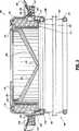
ここで、類似の参照数字がいくつかの図を通して同一または実質的に類似のパーツを識別する図を参照して、図1〜4は、本開示の接近装置を図示する。接近装置100は、一般に、2つの主要構成要素、つまり、長軸方向軸「a」を規定する接近ハウジング102およびこの接近ハウジング102から延びるライナー基部104を備える。ハウジング102は、組立てられたときに、患者の身体に対して位置決め可能であるユニットを提供するいくつかの構成要素を備える。具体的には、ハウジング102は、外側基部106、外側基部106内に配置されるラチェットリング108およびラチェットハブ110を備える。外側基部106、ラチェットリング108およびラチェットハブ110の各々は、好ましくは、構成が中央アパーチャを規定する環状またはリング様であり、ハウジング102内での接近を可能にする。 With reference now to the figures, in which like reference numerals identify the same or substantially similar parts throughout the several views, FIGS. 1-4 illustrate the access device of the present disclosure.
図1〜4と関連して図5〜6を参照して、外側基部106が考察される。外側基部106は、ハウジング102の残りの構成要素を囲う周囲要素として供される。外側基部106は、その下部表面114に隣接して周囲方向に間隔を空けておかれた複数(例えば、2つ)のラチェットアーム112を備える。各ラチェットアーム112は、長軸方向「a」に対して半径方向内側にばね付勢され、ラチェットリング108の構成要素との係合のためにロック棚116を規定する。(図4〜6を参照のこと)1つの好ましい配置では、外側基部106は、プラスチックの弾性材料から一体的に形成され、それによってラチェットアーム112は、通常は内側に付勢されているが、アーム112の爪車を送る作用または移動を収容するために外側に偏向し得る。外側基部102の下部表面114は、表面114の周りで周囲方向に間隔を空けて置かれた複数の突き出た接触小柱118をさらに備える。外側基部106は、図4で方向を示す矢印「B」で示される方向での、ラチェットリング108およびラチェットハブ110に対する長軸方向軸「a」のまわりの回転運動のために適合されている。 With reference to FIGS. 5-6 in conjunction with FIGS. 1-4, the
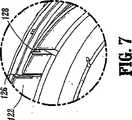
ここで図2〜4を参酌しながら、図7〜8を参照して、ラチェットリング108およびラチェットハブ110は、外側基部106の下方端部の周りに配置される。ラチェットリング108は、外側基部106のラチェットアーム112と協働して外側基部106およびラチェットリング108の相対的位置を選択的にロックする複数の外側ラチェット歯120を備える。ラチェットリング108は、ラチェットハブ110の対応して位置決めされる開口部124(図2)内に受容される、複数の上方向に延びるタブ122(図2および7)をさらに備える。タブ122は、ロック棚126を備え得、このロック棚126は、ラチェットハブ110と係合してラチェットリング108およびラチェットハブ110を固定する。代替の実施形態では、ラチェットリング108およびラチェットハブ110は、単一の構造体に一体的に形成される。好ましい実施形態では、ラチェットリング108およびラチェットハブ110は静止している。ラチェットリング108は、内周壁130内の複数のスロット128および外周壁134のアパーチャ132をさらに備える。ラチェットリング108は、U字型の谷136をさらに規定し(図3)、この谷136は使用の間、患者の皮膚と接触する。 7 to 8 with reference to FIGS. 2 to 4, the
再度図1〜4を参照して、接近ハウジング102は、バルブ支持体138、ダックビルバルブ140および隔壁シール142をさらに備える。バルブ支持体138は、外側基部106内に延びる細長い環状のカラーである。バルブ支持体138の上方表面144は、上方表面144の周りで周囲方向に間隔を空けて置かれた、複数の上方向に延びる小柱146を規定する。ダックビルバルブ140は、バルブ支持体138に取付けられる。ダックビルバルブ140は、好ましくは弾性材料を備える。具体的には、ダックビルバルブ140は、複数のアパーチャ150を有する周縁フランジ148を備える。アパーチャ150は、バルブ支持体138の対応して位置決めされる小柱146を受容してバルブ支持体138に対してバルブ140を固定するような寸法である。ダックビルバルブ140は、下方または遠位フランジ152をさらに備え、この下方または遠位フランジ152は、バルブ支持体138の下方表面154とラチェットハブ110の内部レッジ156との間に位置決めされる。(図3)ダックビルバルブ140は、長軸方向軸に対して斜めに配置され、隣接した関係で終結してスリット160を規定する一対の内壁158を規定する。スリット160は、開口して壁158の偏向により物体の通過を可能にし、腔内の注入ガスの圧力により促進されるように物体が存在しないときは閉じている。すなわち、ダックビルシールは、ゼロ閉鎖シールである。あるいは、他のゼロ封鎖シールもまた、装置100内に組込まれ得る。 Referring again to FIGS. 1-4, the
引き続き図1〜4を参照して、隔壁シール142は、ダックビルバルブ140に隣接して位置決めされる。隔壁シール142は、中央アパーチャ162aを取り囲む周囲シール領域162を備える。周囲領域162は、バルブ支持体112の小柱146の上方端部を受容して隔壁シール142をハウジング102内に固定する複数の開口部164を備える。シール142は、アパーチャ162aを通って挿入される物体の周りで実質的なシールを形成するように適合され、より大きいサイズの物体を収容するように伸長し得る。か隔壁シール142は、好ましくは弾性材料から形成される。隔壁シールとして説明されているが、シール142は、スリットバルブ、バルーンバルブ、ゲルシールまたは当該分野で利用可能な他のあらゆるシールであってもよいことが理解される。1つの実施形態では、シール142は、好ましくは軟質ウレタンゲル、シリコーンゲルなどのようなゲル物質を含み、好ましくは、シール142が、手術部位の周りの挿入および操作の間、外科医の手/または腕の外部表面の周りに一致してシールを形成することを可能にするように圧縮可能な性質を有する。 With continued reference to FIGS. 1-4, the
代替の好ましい実施形態では、シール142は、弾性材料(例えば、ポリイソプレン)から製作され、その弾性材料に隣接して位置決めされる少なくとも1つの布材料の層を有する。シール142は、布材料(fabric manual)とともに成形された弾性材料から製作され得る。耐摩擦性コーティングがシール142に付与され得る。このシールは、同一人に譲渡された米国特許出願番号第10/165,373号(2002年6月6日出願)に開示されており、この出願の内容は、その全体が参考として援用される。ゼロ閉鎖バルブ、隔壁バルブ、スリットバルブ、二重スリットバルブ、膨張可能な嚢、他の発泡体またはゲルバルブ配置物などを含んで他のバルブのタイプも企図される。 In an alternative preferred embodiment, the
引き続いて図1〜4を参照して、ハウジング102は、カバー166をさらに備え、このカバー166は、隔壁シール142の上に位置決めされ、バルブ支持体138、ダックビルバルブ140および隔壁シール142を実質的に囲む。カバー166は、ハウジング102の内部への接近を可能にするアパーチャ168を備える。好ましくは、カバー166は、カバー166をハウジング102内に固定するために、ラチェットリング108またはラチェットハブ110の対応する表面または構造と係合するための構造体を組込む。例えば、カバー166は、ラチェットリング108またはラチェットハブ110内の対応する凹部中にロックする、その外部表面上の複数のタブ166aを備え得る。カバー102をハウジング102内に連結するための他の手段もまた想定される。カバー166、外側基部106、ラチェットリング108、およびラチェットハブ110は、望ましくは、ポリカーボネートのような相対的に剛性のポリマー材料から形成される。 1-4, the
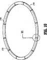
ここで図1〜3および9〜11を参照して、ライナー基部104が考察される。ライナー基部104は、患者の切開部内に位置決めして切開部を内張りして、そして/または切開部が規定する組織を退却し、それによってその下にある体腔への接近を高めることが意図されている。ライナー基部104は、スリーブ168、下部リング170およびスリーブ168のそれぞれの端部に連結された上部リング172を備える。スリーブ168は、管状の構成で配置される可撓性材料のシートであり得、この可撓性シートしては、例えば、ポリエチレン、ポリプロピレンなどが挙げられる。好ましくは、スリーブ168は、図9に示されるように二重壁であり、拡大されたリング様の領域174を規定して下部リング170および上部リング172を収容する。スリーブ168はまた、弾性材料を備え得る。好ましい実施形態では、スリーブ168は管状であるが、スリーブ168が数個の片(例えば、個々のタブなど)を組込み得ることが想定される。スリーブ168は、流体を通さなくなくても通してもよいが、好ましくは組織を通る切開部を汚染から保護する。 Referring now to FIGS. 1-3 and 9-11, the
下部リング170は、切開部を通る位置決めおよび腹腔壁の下の位置決めのために適合されて内壁部分と係合し、それにより切開部に対してスリーブ168を固定する。下部リング170は、好ましくは、切開部を通る通過を容易にするように可撓性であり、腹腔への侵入の後にその元の構成に戻るに十分な弾性を保有する。下部リング170は、図10および11に示されるように、複数の長軸方向の開口部176および環状溝178を備える。溝178は、下部リング170が切開部を通過するとき、下部リング170のそれ自身上への押し潰しを容易にする。代替の実施形態では、リング170は、切開部を通って挿入される間、溝178を組込むことなく、変形するに十分可撓性であり得る。下部リング178は、好ましくは、構成が環状またはリング様であり、弾性材料から製作され得る。下部リング170は、スリーブ168の拡大されたリング様領域174内に収容される。
ここで図2および9を参照して、ライナー基部104の上部リング172は、構成が実質的に下部リング170と同一である。図3に最もよく描写されるように、上部リング172は、スリーブ168の拡大されたリング様領域174内に収容される。組立てられた状態では、上部リング172は、ラチェットリング108のU字型の谷136内に受容され、谷136とラチェットハブ110の下部表面180との間に固定される(図3)。 With reference now to FIGS. 2 and 9, the
ライナー基部104は、複数の張力付与部材182をさらに備え、この張力付与部材182は、スリーブ168の二重壁内に延びる。張力付与部材182は、下部リング170に固定され、スリーブ168から上部リング172中に提供される開口部184を通って外へ延びる。張力付与部材182は、縫合糸を含んで糸、タブなどを備え得る。1つの実施形態では、張力付与部材182の端部182aは、下部リング170内に縫合糸フェラル186で固定される。縫合糸端部182aを下部リング170に連結するための他の手段もまた、想定される。張力付与部材182は、接近ハウジング102の外側基部106の回転の際にスリーブ168内で移動し、下部リング170を上部リング172および接近ハウジング102に向かって変位させる。 The
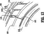
図12〜14に描写されるように、張力付与部材180の外側端部182bは、ラチェットリング108の受容スロット128内に収容され、ラチェットリング108の外壁134の開口部186を通って延びる。張力付与部材182は、縫合糸フェラル188またはアンカー、結び目などの使用を含む従来の手段により、ラチェットリング108の開口部186内に固定される。張力付与部材182は、下部リング170を内部本体の壁と係合させるように、外側基部106の回転の際に、スリーブ168内でスライドして下部リング170を上部リング172に向かって変位させるように適合される。外側基部106の回転によって、張力付与部材182の有効長は短縮される。このような移動はまた、スリーブ168に対して張力付与効果および退却効果を与え、スリーブ168を切開部を規定する組織と係合させ、そしてその組織を退却させる。張力付与部材182は、縫合糸、ケーブル、引締めひもなどを含むあらゆる適切な可撓性部材であり得る。 As depicted in FIGS. 12-14, the
さらなる実施形態では、スリーブは、張力付与部材をスリーブの壁中に組込むか、または張力付与部材およびスリーブが互いに一体であるように、スリーブの上部端部から延びる。 In further embodiments, the sleeve extends from the upper end of the sleeve so that the tensioning member is incorporated into the wall of the sleeve or the tensioning member and the sleeve are integral with each other.
(作動)
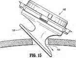
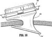
手で支援される腹腔鏡外科手順に関連する接近装置100の使用が考察される。当該分野で慣用的であるように、腸腔がガス注入され、例えば、トロカールを用いて腔内に切開部が作製されて、腔への接近が提供される。その後で、図15〜16に描写されるように、ライナー基部104が切開部内に導入される。具体的には、下部リング170がその切開部を通され、体腔内に配置される。注記されるように、下部リング170は、切開部を通る通過を容易にするために、それ自身の上に狭められ、次いで解放されて腔内で(その固有の弾性の影響の下で)下部リング170がその通常の状態に戻ることを可能にする。ライナースリーブ168は、下部リング170から切開部を通って延び、以前に考察したように、切開部を内張りする。(Operation)
Consider the use of the
手順は、ラチェットリング108の谷136の外側表面が切開部を取り囲む組織と係合しながら、接近ハウジング102を外部身体組織に隣接して位置決めすることにより続けられる。その後で、切開部のサイズを大きくすることが望ましくなったとき、外側基部106は、図4の方向を示す矢印「B」の方向に回転される。外側基部106が回転するにつれて、外側基部106の係合する小柱118は、張力付与部材182と係合し、張力付与部材182を図17に示される配置から図18に示される配置に偏向させる。この移動の間、張力付与部材182は、ライナー基部104の下部リング170を上部リング172に向かって引く。同時に、張力付与効果がスリーブ168に与えられ、それによりスリーブ168に組織を退却させる。理解されるように、外側基部106の回転を介する張力付与部材182の偏向量は、連動するラチェット機構を介して選択的に制御可能である。加えて、スリーブ168は、張力を与えられ、外科医がスリーブ168を引張るかまたは別な様に配置することを必要とすることなく、組織は退却される。外側基部106は、ラチェットリング108に対して、ライナー基部104の下部リング170を体腔の内部壁との係合へと引張るに十分、回転され得る。図20は、スリーブ168を切開部を規定する組織「t」を退却させて、体腔の内壁と係合された下部リング170を図示する。 The procedure continues by positioning the
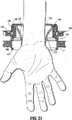
接近装置100を図20のこの位置において、手で支援される外科手術は、次いで、接近ハウジング102のシール142、140を通して、そして体腔の中へ外科医の手および腕を前進させることにより実施される(図21)。シール142は、腕の周りで流体密のシールを形成する。所望の手で支援される手順が、次いで実施され得る。 In this position of FIG. 20, hand-assisted surgery is then performed by advancing the surgeon's hand and arm through the
接近装置100の1つの他の顕著な特徴は、腹腔鏡機器との使用のために手接近装置100を転換し得る能力である。この点に関して、そして図22〜24を参照して、トロカールアダプター200が提供される。トロカールアダプター200は、アダプター基部202およびアダプター基部202に取付けられるバルブアセンブリ204を備える。アダプター基部202は、トロカールスリーブ206、スリーブ206から延びる内壁208および周囲フランジ210を備える。トロカールスリーブ206は、外科用機器の通過に適した内寸を規定する長軸方向開口部を有する管様構造体である。トロカールスリーブ206の近位端は、バルブアセンブリ204への取付けのために、内壁208を越えて延びる。アダプター基部202は、好ましくは単一ユニットとして一体形成され、射出成型技術によって適切なポリマー材料から製作され得る。あるいは、アダプター基部202は、ステンレス鋼、チタン、チタン合金などのような適切な生体適合性金属材料から形成され得る。 One other salient feature of the
アダプター基部202は、好ましくは接近ハウジング102に取り外し可能に取付けられる。1つの好ましい配置では、アダプター基部202は、カバー166の凹部166aと係合する、その下部表面から突き出る周囲タブ212を備え、基部202をカバーに固定する。アダプター基部202を接近ハウジング102に取り外し可能に連結するための他の手段も想定され、それらとしては、差込みカップリング、摩擦嵌め、トング、溝などが挙げられる。アダプター基部202はまた、接近ハウジング102に繋ぎ止められ、拡張式配置が提供され得る。
バルブアセンブリ204は、トロカールスリーブに取付けて、直径が約3mm〜約15mmの範囲の内視鏡器具の周りに流体密なシールを形成するように適合されたあらゆる従来のトロカールシールシステムであってよい。1つの好ましい実施形態では、バルブアセンブリ204は、Norwalk、ConnecticutのUnited States Surgical Corporationから、VERSAPORTPLUSTMの商標名で入手可能なタイプのものである。VERSAPORTPLUSTMシールは、バルブハウジング214、ハウジング内に取付けられたジンバルバルブ216、およびバルブハウジング214からトロカールスリーブ206の中に延びるゼロ閉鎖バルブまたはダックビルバルブ218を備える。ジンバルバルブ216は、バルブハウジング214内で中央回転軸の周りに旋回または回転するように適合され、バルブアセンブリ204を通って挿入される器具の中心を逸れた操作に適応する。ダックビルバルブ218は、器具の存在下で開き、器具がないときは閉じてゼロ閉鎖バルブとして機能するように適合されている。バルブハウジング214は、接着剤、差込みカップリングなどを含むあらゆる従来の手段を介して、トロカールスリーブ200の近位端に連結される。アダプター200の中への組み込みのための他のバルブアセンブリもまた想定され、そのようなバルブアセンブリとしては、同一出願人に譲渡された米国特許第6,482,181号、同第5,820,600号、同第RE36,702号、および出願番号第09/706,643号(2000年11月6日出願)に開示されるバルブアセンブリが挙げられる。これらの特許文献の各々の全体の内容は、参考として援用されている。いったん取付けられると、トロカールスリーブ206は、シール142のアパーチャ162aを通って延びる。シール142は、トロカールスリーブ206の外側表面の周りに流体密のシールを形成する。器具は、バルブアセンブリ204およびトロカールスリーブ206を通って導入され、所望の手順が実施される。言及されたように、バルブアセンブリ204のジンバルバルブ216は、器具の周りに流体密のシールを形成し、作動部位内での器具の操作を可能にする。The
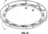
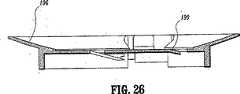
図25〜26は、接近ハウジング102の外側基部106の代替の実施形態を図示する。この実施形態によれば、外側基部106の回転の間、張力付与部材182と係合する接触小柱118は、フォーク190で置き換えられている。フォーク190は、一定の斜めの角度で外側基部106の下部縫合糸から下向きに突き出ており、外側基部106の回転の間、張力付与部材182を捕捉する。他のすべての点で、接近装置100は、図1の実施形態に関連して説明されたのと同じ様式で作動する。 FIGS. 25-26 illustrate an alternative embodiment of the
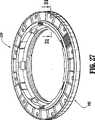
図27〜32は、本開示の別の代替の実施形態を図示する。この実施形態によれば、接近装置300は、ホイールマウント304を有する接近ハウジング302、ホイールマウント304に取付けられるホイールハブ306、およびギヤリング308を備える。ホイールマウント304およびホイールハブ306は、ホイールマウント304のタブ310とホイールハブ306のスロット312との対応する係合を介して互いに固定される。ホイールマウント304およびホイールハブ306は、静止している。ホイールマウント304は、ホイールマウント304の周囲の周りに取付けられた複数の歯車316備える。歯車316は、それらのそれぞれの個々の軸の周りで回転する。歯車316をホイールマウント304に取付けるためのあらゆる手段が想定される。各歯車316は、歯車316の回転軸を横断する方向に延びるスロット状の開口部318を備える。スロット状の開口部318は、ライナー基部104の張力付与部材182の端部を受容する。張力付与部材182の極端部は、ホイールマウント304の周囲の周りに配置された縫合糸マウント320との固定された係合により、ホイール部材304に固定される。 27-32 illustrate another alternative embodiment of the present disclosure. According to this embodiment, the access device 300 includes an
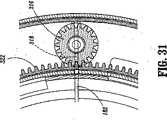
ギヤリング308は、その下部表面から突き出る複数のギヤの歯322を備える(図29)。ギヤの歯322は、ホイールマウント304およびホイールハブ308に対するギヤリング308の回転の間、歯車316の歯と係合する。ギヤリング308も、タブ324を備える。タブ324は、半径方向内側にばね付勢され得、ギヤリング308の回転の際に、ギヤハブ306の対応する開口部326内に受容されるように適合されている。このようにして、ギヤリング308は、歯車304およびギヤハブ306に対する所望の回転配向で選択的に固定され得る。
接近装置300のライナー基部104は、図1に関して説明されたライナー基部104と同一である。 The
図31〜32は、接近装置300の作動を図示する。ライナー基部104を切開部内に位置決めした後、ギヤリング308は、図32に示される方向を示す矢印の方向に回転され、歯車316をそのそれぞれの軸の周りに回転させる。この回転は、図32に描写される様式で、張力付与部材182の変位を引き起こし、それにより張力付与部材182に張力付与効果を与える。望ましくは、歯車316は、張力付与部材を巻き取るための一体型スプールを備える。ライナー基部104の内側リング170は、従って、上方向に、好ましくは体腔の壁と係合して引かれる。加えて、このような作用は、ライナー基部104のスリーブ168に、図1に関連して以前に説明された様式で組織を退却させる。留意されるように、ギヤリング308のタブ324は、歯車304およびギヤハブ306に対して所望の回転関係でギヤリング308を選択的に固定する。より大きい張力または退却が必要とされる場合、ギヤリングは、さらに回転されて、タブ324が、ギヤハブ306の次の連続する開口部326中に受容されることを可能にし得る。 31-32 illustrate the operation of the access device 300. After positioning the
このようにして、本開示の接近装置は、手で支援される腹腔鏡外科技術の間の組織の選択的な退却を提供する。さらに、この装置は、手で支援される腹腔鏡手順およびより従来の機器に支援される腹腔鏡手順と組合せて利用され得る。この融通性および適合性は、腹腔内で必要とされる切開部の数を有意に減少させ、従って、患者の外傷および感染を最小にし、そして回復時間を改善する。 In this way, the access device of the present disclosure provides for selective retraction of tissue during a manually assisted laparoscopic surgical technique. In addition, the device can be utilized in combination with hand-assisted laparoscopic procedures and more traditional instrument-assisted laparoscopic procedures. This flexibility and compatibility significantly reduces the number of incisions required in the abdominal cavity, thus minimizing patient trauma and infection and improving recovery time.
本明細書中に開示される実施形態に対して、種々の改変がなされ得ることが理解される。それゆえに、上記の記載は、限定的と解釈されるべきではなく、単に好ましい実施形態の例示として解釈されるべきである。当業者は、添付の特許請求の範囲の範囲および趣旨内の他の改変を想定する。 It will be understood that various modifications may be made to the embodiments disclosed herein. Therefore, the above description should not be construed as limiting, but merely as exemplifications of preferred embodiments. Those skilled in the art will envision other modifications within the scope and spirit of the claims appended hereto.
Claims (16)
Translated fromJapanese身体組織内の開口部を通る挿入のために適合された内側部材であって、該身体内に位置決めするためのものである、内側部材;
該内側部材から延びる少なくとも1つの張力付与要素;
該身体の外部に位置決めするための外側部材であって、第1の要素および第2の要素を備え、該第2の要素は、該少なくとも1つの張力付与要素に作動可能に連結され、そして該身体内の開口部を規定する組織の退却を引き起こすための、該第1の要素に対する回転運動のために適合された外側部材;および
該内側部材に連結され、該身体組織内の該開口部を通して該内側部材から延びるような寸法であるライナー部材をさらに備え、該ライナー部材は、物体の通過を可能にするために該ライナー部材を通る通路を開き、該少なくとも1つの張力付与要素は、該ライナー部材内に包埋されており、そして該ライナー部材に対して移動可能である、ライナー部材、
を備え、
該身体組織内の該開口部の中への挿入の際に、該ライナー部材の少なくとも一部分は、該身体組織に隣接して配置される、外科用接近装置。A surgical access device,
An inner member adapted for insertion through an opening in body tissue for positioning within the body;
At least one tensioning element extending from the inner member;
An outer member for positioning outside the body, comprising a first element and a second element, wherein the second element is operably connected to the at least one tensioning element; and An outer member adapted for rotational movement relative to the first element to cause a retraction of tissue defining an opening in the body; and coupled to the inner member and through the opening in the body tissue further comprising a liner member which is dimensioned to extend from the inner member, the linermember-out a passage through the liner member to permit passage of an objectopens, one tensioning element the at least, said A liner member embedded in the liner member and movable relative to the liner member;
With
A surgical access device, wherein at least a portion of the liner member is positionedadjacent to the body tissue upon insertion into the opening in the body tissue.
ライナー基部であって、
身体内に位置決めするために、身体組織内の開口部を通る挿入のために適合された内側部材;
該内側部材に連結され、かつ該身体組織内の該開口部を通って該内側部材から延びるような寸法であるスリーブ部材であって、物体の通過を可能にするために、該スリーブ部材を通る通路を規定する、スリーブ部材;および
該内側部材に連結され、かつ該スリーブ部材内に包埋されている複数の張力付与要素であって、該スリーブ部材に対して張力付与効果をもたらすためのものであり、該張力付与要素は、該スリーブ部材に対して移動可能である、張力付与要素、
を備え、該身体組織内の該開口部の中への挿入の際に、該スリーブ部材の少なくとも一部分は、該身体組織と該少なくとも1つの張力付与要素との間に配置される、ライナー基部;ならびに
該身体の外側に位置決めするための接近ハウジングであって、該接近ハウジングは、第1の要素および第2の要素を備え、該第2の要素は、該張力付与要素に作動可能に連結され、かつ該第1の要素に対する回転運動のために適合され、該張力付与要素に該内側部材を該接近ハウジングに向かって変位させ、そして該スリーブ部材に該身体内の該開口部を規定する組織と係合しかつ退却させる、接近ハウジング、
を備える、外科用接近装置。A surgical access device,
A liner base,
An inner member adapted for insertion through an opening in body tissue for positioning within the body;
A sleeve member coupled to the inner member and dimensioned to extend from the inner member through the opening in the body tissue, through the sleeve member to allow passage of an object defining a passage, the sleeve member; is connected to and the inner member, and a plurality of tensioning elements thatare embedded in thesleeve member, intended to provide a tensioning effect on the sleeve member deris, the tension imparting element is Rumovable der relative to the sleeve member, the tensioning element,
A liner base, wherein at least a portion of the sleeve member is disposed between the body tissue and the at least one tensioning element upon insertion into the opening in the body tissue; And an access housing for positioning outside the body, the access housing comprising a first element and a second element, the second element being operably connected to the tensioning element And adapted for rotational movement relative to the firstelement , causing the tensioning element to displace the inner member toward the access housing and defining the opening in the body in the sleeve member An approach housing, which engages and retracts
Surgical access device comprising:
Applications Claiming Priority (3)
| Application Number | Priority Date | Filing Date | Title |
|---|---|---|---|
| US55967804P | 2004-04-05 | 2004-04-05 | |
| US60/559,678 | 2004-04-05 | ||
| PCT/US2005/011555WO2005097019A2 (en) | 2004-04-05 | 2005-04-05 | Surgical hand access apparatus |
Related Child Applications (1)
| Application Number | Title | Priority Date | Filing Date |
|---|---|---|---|
| JP2010263020ADivisionJP2011062544A (en) | 2004-04-05 | 2010-11-25 | Surgical hand access apparatus |
Publications (2)
| Publication Number | Publication Date |
|---|---|
| JP2008504050A JP2008504050A (en) | 2008-02-14 |
| JP4868602B2true JP4868602B2 (en) | 2012-02-01 |
Family
ID=35125593
Family Applications (3)
| Application Number | Title | Priority Date | Filing Date |
|---|---|---|---|
| JP2007506367AExpired - Fee RelatedJP4868602B2 (en) | 2004-04-05 | 2005-04-05 | Surgical hand access device |
| JP2010263020AWithdrawnJP2011062544A (en) | 2004-04-05 | 2010-11-25 | Surgical hand access apparatus |
| JP2012237664AWithdrawnJP2013017843A (en) | 2004-04-05 | 2012-10-29 | Surgical hand access apparatus |
Family Applications After (2)
| Application Number | Title | Priority Date | Filing Date |
|---|---|---|---|
| JP2010263020AWithdrawnJP2011062544A (en) | 2004-04-05 | 2010-11-25 | Surgical hand access apparatus |
| JP2012237664AWithdrawnJP2013017843A (en) | 2004-04-05 | 2012-10-29 | Surgical hand access apparatus |
Country Status (6)
| Country | Link |
|---|---|
| US (4) | US7393322B2 (en) |
| EP (2) | EP2407091B1 (en) |
| JP (3) | JP4868602B2 (en) |
| AU (2) | AU2005231485B2 (en) |
| CA (1) | CA2560154C (en) |
| WO (1) | WO2005097019A2 (en) |
Families Citing this family (278)
| Publication number | Priority date | Publication date | Assignee | Title |
|---|---|---|---|---|
| US7344547B2 (en) | 1998-09-15 | 2008-03-18 | Phavel Systems, Inc. | Laparoscopic instruments and trocar systems and related surgical method |
| US7998068B2 (en) | 1998-12-01 | 2011-08-16 | Atropos Limited | Instrument access device |
| US7559893B2 (en) | 1998-12-01 | 2009-07-14 | Atropos Limited | Wound retractor device |
| US6254534B1 (en) | 1999-10-14 | 2001-07-03 | Atropos Limited | Retractor |
| JP5190169B2 (en) | 2000-10-19 | 2013-04-24 | アプライド メディカル リソーシーズ コーポレイション | Surgical access instruments and methods |
| EP2422829B1 (en) | 2001-08-14 | 2013-03-06 | Applied Medical Resources Corporation | Surgical access sealing apparatus |
| US6958037B2 (en) | 2001-10-20 | 2005-10-25 | Applied Medical Resources Corporation | Wound retraction apparatus and method |
| EP2343032B1 (en) | 2002-06-05 | 2012-05-09 | Applied Medical Resources Corporation | Wound retractor |
| US9271753B2 (en) | 2002-08-08 | 2016-03-01 | Atropos Limited | Surgical device |
| US20050020884A1 (en) | 2003-02-25 | 2005-01-27 | Hart Charles C. | Surgical access system |
| CA2533204A1 (en) | 2003-08-06 | 2005-02-17 | Applied Medical Resources Corporation | Surgical device with tack-free gel and method of manufacture |
| US7163510B2 (en) | 2003-09-17 | 2007-01-16 | Applied Medical Resources Corporation | Surgical instrument access device |
| US7753901B2 (en) | 2004-07-21 | 2010-07-13 | Tyco Healthcare Group Lp | Laparoscopic instrument and cannula assembly and related surgical method |
| US8764765B2 (en)* | 2003-09-23 | 2014-07-01 | Covidien Lp | Laparoscopic instrument and related surgical method |
| WO2005097234A2 (en)* | 2004-04-05 | 2005-10-20 | Tyco Healthcare Group Lp | Surgical hand access apparatus |
| EP2407091B1 (en)* | 2004-04-05 | 2013-08-28 | Covidien LP | Surgical hand access apparatus |
| US8961407B2 (en) | 2004-07-21 | 2015-02-24 | Covidien Lp | Surgical port assembly |
| US8118735B2 (en)* | 2005-04-08 | 2012-02-21 | Ethicon Endo-Surgery, Inc. | Rotational control for a hand assisted laparoscopic seal assembly |
| US20060247678A1 (en)* | 2005-04-08 | 2006-11-02 | Weisenburgh William B Ii | Surgical instrument system |
| JP2009501045A (en) | 2005-07-15 | 2009-01-15 | アトロポス・リミテッド | Wound retractor |
| AU2006304141B2 (en) | 2005-10-14 | 2012-07-05 | Applied Medical Resources Corporation | Gel cap for wound retractor |
| US8425410B2 (en)* | 2008-09-30 | 2013-04-23 | Ethicon Endo-Surgery, Inc. | Surgical access device with protective element |
| US8926506B2 (en) | 2009-03-06 | 2015-01-06 | Ethicon Endo-Surgery, Inc. | Methods and devices for providing access into a body cavity |
| US8251900B2 (en)* | 2009-03-06 | 2012-08-28 | Ethicon Endo-Surgery, Inc. | Surgical access devices and methods providing seal movement in predefined paths |
| US8690831B2 (en) | 2008-04-25 | 2014-04-08 | Ethicon Endo-Surgery, Inc. | Gas jet fluid removal in a trocar |
| US8961406B2 (en) | 2009-03-06 | 2015-02-24 | Ethicon Endo-Surgery, Inc. | Surgical access devices and methods providing seal movement in predefined movement regions |
| US8430811B2 (en) | 2008-09-30 | 2013-04-30 | Ethicon Endo-Surgery, Inc. | Multiple port surgical access device |
| US8357085B2 (en) | 2009-03-31 | 2013-01-22 | Ethicon Endo-Surgery, Inc. | Devices and methods for providing access into a body cavity |
| US8485970B2 (en) | 2008-09-30 | 2013-07-16 | Ethicon Endo-Surgery, Inc. | Surgical access device |
| US8206294B2 (en)* | 2008-09-30 | 2012-06-26 | Ethicon Endo-Surgery, Inc. | Surgical access device with flexible seal channel |
| US8579807B2 (en) | 2008-04-28 | 2013-11-12 | Ethicon Endo-Surgery, Inc. | Absorbing fluids in a surgical access device |
| US8821391B2 (en) | 2009-03-06 | 2014-09-02 | Ethicon Endo-Surgery, Inc. | Methods and devices for providing access into a body cavity |
| US20100081863A1 (en)* | 2008-09-30 | 2010-04-01 | Ethicon Endo-Surgery, Inc. | Methods and devices for performing gastrectomies and gastroplasties |
| US20080011307A1 (en)* | 2006-07-12 | 2008-01-17 | Beckman Andrew T | Hand assisted laparoscopic device |
| EP2056922B1 (en)* | 2006-08-04 | 2018-03-28 | Northgate Technologies, Inc. | In-dwelling port for access into a body |
| US7749161B2 (en)* | 2006-12-01 | 2010-07-06 | Ethicon Endo-Surgery, Inc. | Hand assisted laparoscopic device |
| US7967748B2 (en)* | 2006-12-15 | 2011-06-28 | Ethicon Endo-Surgery, Inc. | Resiliently supported seal cap for hand assisted laparoscopic surgical procedures |
| US7819800B2 (en)* | 2006-12-15 | 2010-10-26 | Ethicon Endo-Surgery, Inc. | Fully automated iris seal for hand assisted laparoscopic surgical procedures |
| US8197404B2 (en)* | 2006-12-15 | 2012-06-12 | Ethicon Endo-Surgery, Inc. | Handoscopy interwoven layered seal laparoscopic disk |
| US7655004B2 (en) | 2007-02-15 | 2010-02-02 | Ethicon Endo-Surgery, Inc. | Electroporation ablation apparatus, system, and method |
| EP2117630A4 (en)* | 2007-02-20 | 2013-08-07 | Covidien Lp | Flexible external cannula sheath |
| US8070770B2 (en)* | 2007-02-22 | 2011-12-06 | Ethicon Endo-Surgery, Inc. | Iris valve with novel locking mechanism |
| JP5191998B2 (en)* | 2007-02-22 | 2013-05-08 | エシコン・エンド−サージェリィ・インコーポレイテッド | Throttle valve with new locking mechanism and control ring |
| US8075482B2 (en) | 2007-02-22 | 2011-12-13 | Ethicon Endo-Surgery, Inc. | IRIS valve with control ring |
| US7678046B2 (en)* | 2007-03-06 | 2010-03-16 | Ethicon Endo-Surgery, Inc. | Hand assisted laparoscopic seal assembly with a ratchet mechanism |
| US8002786B2 (en)* | 2007-03-09 | 2011-08-23 | Ethicon Endo-Surgery, Inc. | Hand assisted laparoscopic seal assembly with deflection feature |
| AU2008233166B2 (en) | 2007-03-30 | 2013-05-16 | Covidien Lp | Laparoscopic port assembly |
| US7922656B2 (en)* | 2007-04-04 | 2011-04-12 | Ethicon Endo-Surgery, Inc. | Hand assisted laparoscopic seal assembly with detachable attachment ring |
| US7846123B2 (en) | 2007-04-24 | 2010-12-07 | Emory University | Conduit device and system for implanting a conduit device in a tissue wall |
| US8075572B2 (en) | 2007-04-26 | 2011-12-13 | Ethicon Endo-Surgery, Inc. | Surgical suturing apparatus |
| US8100922B2 (en) | 2007-04-27 | 2012-01-24 | Ethicon Endo-Surgery, Inc. | Curved needle suturing tool |
| US20080265512A1 (en)* | 2007-04-27 | 2008-10-30 | Beckman Andrew T | Hand assisted laparoscopic seal apparatus with a fast recovery foam core |
| WO2008141291A1 (en) | 2007-05-11 | 2008-11-20 | Applied Medical Resources Corporation | Surgical retractor with gel pad |
| EP2146644A4 (en) | 2007-05-11 | 2012-07-18 | Applied Med Resources | Surgical retractor |
| US8177713B2 (en)* | 2007-05-15 | 2012-05-15 | Ethicon Endo-Surgery, Inc. | Motor-driven laparoscopic seal assembly |
| CA2632369A1 (en) | 2007-05-31 | 2008-11-30 | Tyco Healthcare Group Lp | Access apparatus with shallow zero closure valve |
| US8657740B2 (en) | 2007-06-05 | 2014-02-25 | Atropos Limited | Instrument access device |
| US8100929B2 (en) | 2007-06-29 | 2012-01-24 | Ethicon Endo-Surgery, Inc. | Duckbill seal with fluid drainage feature |
| US20090069837A1 (en)* | 2007-08-20 | 2009-03-12 | Atropos Limited | Hand and instrument access device |
| US8568410B2 (en) | 2007-08-31 | 2013-10-29 | Ethicon Endo-Surgery, Inc. | Electrical ablation surgical instruments |
| US8579897B2 (en) | 2007-11-21 | 2013-11-12 | Ethicon Endo-Surgery, Inc. | Bipolar forceps |
| US8262655B2 (en) | 2007-11-21 | 2012-09-11 | Ethicon Endo-Surgery, Inc. | Bipolar forceps |
| US20090093752A1 (en)* | 2007-10-05 | 2009-04-09 | Tyco Healthcare Group Lp | Seal anchor for use in surgical procedures |
| US20100100043A1 (en)* | 2007-10-05 | 2010-04-22 | Racenet Danyel J | Flexible Access Device For Use In Surgical Procedure |
| US8273017B1 (en) | 2007-10-30 | 2012-09-25 | Ethicon Endo-Surgery, Inc. | Surgical access port with ring actuated latching mechanism |
| US8142354B1 (en) | 2007-10-30 | 2012-03-27 | Ethicon Endo-Surgery, Inc. | Laminated surgical access port |
| US20090112059A1 (en) | 2007-10-31 | 2009-04-30 | Nobis Rudolph H | Apparatus and methods for closing a gastrotomy |
| US8480657B2 (en) | 2007-10-31 | 2013-07-09 | Ethicon Endo-Surgery, Inc. | Detachable distal overtube section and methods for forming a sealable opening in the wall of an organ |
| US9636187B2 (en)* | 2007-11-21 | 2017-05-02 | Misonix Incorporated | Atomized-fluid shield for surgery and method of use |
| US7976501B2 (en) | 2007-12-07 | 2011-07-12 | Ethicon Endo-Surgery, Inc. | Trocar seal with reduced contact area |
| CA2711116C (en)* | 2008-01-22 | 2017-08-29 | Applied Medical Resources Corporation | Surgical instrument access device |
| US8262680B2 (en) | 2008-03-10 | 2012-09-11 | Ethicon Endo-Surgery, Inc. | Anastomotic device |
| US8636686B2 (en) | 2008-04-28 | 2014-01-28 | Ethicon Endo-Surgery, Inc. | Surgical access device |
| US8870747B2 (en)* | 2008-04-28 | 2014-10-28 | Ethicon Endo-Surgery, Inc. | Scraping fluid removal in a surgical access device |
| USD700326S1 (en) | 2008-04-28 | 2014-02-25 | Ethicon Endo-Surgery, Inc. | Trocar housing |
| US8273060B2 (en) | 2008-04-28 | 2012-09-25 | Ethicon Endo-Surgery, Inc. | Fluid removal in a surgical access device |
| US11235111B2 (en) | 2008-04-28 | 2022-02-01 | Ethicon Llc | Surgical access device |
| US9358041B2 (en) | 2008-04-28 | 2016-06-07 | Ethicon Endo-Surgery, Llc | Wicking fluid management in a surgical access device |
| US8568362B2 (en)* | 2008-04-28 | 2013-10-29 | Ethicon Endo-Surgery, Inc. | Surgical access device with sorbents |
| US7981092B2 (en) | 2008-05-08 | 2011-07-19 | Ethicon Endo-Surgery, Inc. | Vibratory trocar |
| US8679003B2 (en) | 2008-05-30 | 2014-03-25 | Ethicon Endo-Surgery, Inc. | Surgical device and endoscope including same |
| US8771260B2 (en) | 2008-05-30 | 2014-07-08 | Ethicon Endo-Surgery, Inc. | Actuating and articulating surgical device |
| US8652150B2 (en) | 2008-05-30 | 2014-02-18 | Ethicon Endo-Surgery, Inc. | Multifunction surgical device |
| US8317806B2 (en) | 2008-05-30 | 2012-11-27 | Ethicon Endo-Surgery, Inc. | Endoscopic suturing tension controlling and indication devices |
| US8114072B2 (en) | 2008-05-30 | 2012-02-14 | Ethicon Endo-Surgery, Inc. | Electrical ablation device |
| US8070759B2 (en) | 2008-05-30 | 2011-12-06 | Ethicon Endo-Surgery, Inc. | Surgical fastening device |
| US8906035B2 (en) | 2008-06-04 | 2014-12-09 | Ethicon Endo-Surgery, Inc. | Endoscopic drop off bag |
| US8403926B2 (en) | 2008-06-05 | 2013-03-26 | Ethicon Endo-Surgery, Inc. | Manually articulating devices |
| US20090312697A1 (en)* | 2008-06-17 | 2009-12-17 | Tyco Healthcare Group Lp | Surgical seal with variable diameter |
| US8025640B2 (en) | 2008-06-27 | 2011-09-27 | Tyco Healthcare Group Lp | Pressurized surgical valve |
| US8361112B2 (en) | 2008-06-27 | 2013-01-29 | Ethicon Endo-Surgery, Inc. | Surgical suture arrangement |
| US8888792B2 (en) | 2008-07-14 | 2014-11-18 | Ethicon Endo-Surgery, Inc. | Tissue apposition clip application devices and methods |
| US8262563B2 (en) | 2008-07-14 | 2012-09-11 | Ethicon Endo-Surgery, Inc. | Endoscopic translumenal articulatable steerable overtube |
| US8211125B2 (en) | 2008-08-15 | 2012-07-03 | Ethicon Endo-Surgery, Inc. | Sterile appliance delivery device for endoscopic procedures |
| US8529563B2 (en) | 2008-08-25 | 2013-09-10 | Ethicon Endo-Surgery, Inc. | Electrical ablation devices |
| US8241204B2 (en) | 2008-08-29 | 2012-08-14 | Ethicon Endo-Surgery, Inc. | Articulating end cap |
| US8480689B2 (en) | 2008-09-02 | 2013-07-09 | Ethicon Endo-Surgery, Inc. | Suturing device |
| US8409200B2 (en) | 2008-09-03 | 2013-04-02 | Ethicon Endo-Surgery, Inc. | Surgical grasping device |
| US8114119B2 (en) | 2008-09-09 | 2012-02-14 | Ethicon Endo-Surgery, Inc. | Surgical grasping device |
| US8328761B2 (en)* | 2008-09-30 | 2012-12-11 | Ethicon Endo-Surgery, Inc. | Variable surgical access device |
| US8337394B2 (en) | 2008-10-01 | 2012-12-25 | Ethicon Endo-Surgery, Inc. | Overtube with expandable tip |
| USD738500S1 (en) | 2008-10-02 | 2015-09-08 | Covidien Lp | Seal anchor for use in surgical procedures |
| DE102008051111B4 (en)* | 2008-10-09 | 2013-01-24 | Reiner Kunz | Holding and guiding device for an endoscopic instrument |
| CA2739910C (en) | 2008-10-13 | 2017-06-06 | Applied Medical Resources Corporation | Single port access system |
| TWI520755B (en)* | 2008-10-28 | 2016-02-11 | 醫藥成分公司 | Venous access port assembly and method of assembly |
| US8147405B2 (en) | 2008-10-30 | 2012-04-03 | Ethicon Endo-Surgery, Inc. | Surgical access port with multilayered tortuous path seal |
| US8157834B2 (en) | 2008-11-25 | 2012-04-17 | Ethicon Endo-Surgery, Inc. | Rotational coupling device for surgical instrument with flexible actuators |
| US8172772B2 (en) | 2008-12-11 | 2012-05-08 | Ethicon Endo-Surgery, Inc. | Specimen retrieval device |
| US8361066B2 (en) | 2009-01-12 | 2013-01-29 | Ethicon Endo-Surgery, Inc. | Electrical ablation devices |
| US8828031B2 (en) | 2009-01-12 | 2014-09-09 | Ethicon Endo-Surgery, Inc. | Apparatus for forming an anastomosis |
| US9226772B2 (en) | 2009-01-30 | 2016-01-05 | Ethicon Endo-Surgery, Inc. | Surgical device |
| US8252057B2 (en) | 2009-01-30 | 2012-08-28 | Ethicon Endo-Surgery, Inc. | Surgical access device |
| US8037591B2 (en) | 2009-02-02 | 2011-10-18 | Ethicon Endo-Surgery, Inc. | Surgical scissors |
| US9737334B2 (en)* | 2009-03-06 | 2017-08-22 | Ethicon Llc | Methods and devices for accessing a body cavity |
| US7938804B2 (en)* | 2009-03-30 | 2011-05-10 | Tyco Healthcare Group Lp | Surgical access apparatus with seal and closure valve assembly |
| US8317690B2 (en) | 2009-03-31 | 2012-11-27 | Covidien Lp | Foam port and introducer assembly |
| US20100249520A1 (en) | 2009-03-31 | 2010-09-30 | Shelton Iv Frederick E | Method Of Surgical Access |
| US11224460B2 (en)* | 2009-03-31 | 2022-01-18 | Cilag Gmbh International | Access device |
| US8323184B2 (en) | 2009-03-31 | 2012-12-04 | Covidien Lp | Surgical access port and associated introducer mechanism |
| US8353824B2 (en) | 2009-03-31 | 2013-01-15 | Ethicon Endo-Surgery, Inc. | Access method with insert |
| US8945163B2 (en) | 2009-04-01 | 2015-02-03 | Ethicon Endo-Surgery, Inc. | Methods and devices for cutting and fastening tissue |
| US20100261972A1 (en)* | 2009-04-08 | 2010-10-14 | Ethicon Endo-Surgery, Inc. | Surgical Access Device with One Time Seal |
| US8137267B2 (en) | 2009-04-08 | 2012-03-20 | Ethicon Endo-Surgery, Inc. | Retractor with flexible sleeve |
| US8257251B2 (en) | 2009-04-08 | 2012-09-04 | Ethicon Endo-Surgery, Inc. | Methods and devices for providing access into a body cavity |
| US8419635B2 (en)* | 2009-04-08 | 2013-04-16 | Ethicon Endo-Surgery, Inc. | Surgical access device having removable and replaceable components |
| US8475490B2 (en) | 2009-06-05 | 2013-07-02 | Ethicon Endo-Surgery, Inc. | Methods and devices for providing access through tissue to a surgical site |
| US8795163B2 (en) | 2009-06-05 | 2014-08-05 | Ethicon Endo-Surgery, Inc. | Interlocking seal components |
| US8033995B2 (en) | 2009-06-05 | 2011-10-11 | Ethicon Endo-Surgery, Inc. | Inflatable retractor with insufflation and method |
| US8241209B2 (en) | 2009-06-05 | 2012-08-14 | Ethicon Endo-Surgery, Inc. | Active seal components |
| US8465422B2 (en) | 2009-06-05 | 2013-06-18 | Ethicon Endo-Surgery, Inc. | Retractor with integrated wound closure |
| US8361109B2 (en) | 2009-06-05 | 2013-01-29 | Ethicon Endo-Surgery, Inc. | Multi-planar obturator with foldable retractor |
| US9078695B2 (en) | 2009-06-05 | 2015-07-14 | Ethicon Endo-Surgery, Inc. | Methods and devices for accessing a body cavity using a surgical access device with modular seal components |
| US8257252B2 (en) | 2009-08-06 | 2012-09-04 | Tyco Healthcare Group Lp | Elongated seal anchor for use in surgical procedures |
| US8454502B2 (en)* | 2009-08-06 | 2013-06-04 | Covidien Lp | Surgical device having a port with an undercut |
| CA2771337C (en) | 2009-08-31 | 2018-05-01 | Jeremy J. Albrecht | Multifunctional surgical access system |
| WO2011033495A1 (en) | 2009-09-17 | 2011-03-24 | Atropos Limited | An instrument access device |
| US8932212B2 (en) | 2009-10-01 | 2015-01-13 | Covidien Lp | Seal anchor with non-parallel lumens |
| US9474540B2 (en) | 2009-10-08 | 2016-10-25 | Ethicon-Endo-Surgery, Inc. | Laparoscopic device with compound angulation |
| US20110098704A1 (en) | 2009-10-28 | 2011-04-28 | Ethicon Endo-Surgery, Inc. | Electrical ablation devices |
| US8608652B2 (en) | 2009-11-05 | 2013-12-17 | Ethicon Endo-Surgery, Inc. | Vaginal entry surgical devices, kit, system, and method |
| US8376938B2 (en) | 2009-11-20 | 2013-02-19 | Ethicon Endo-Surgery, Inc. | Discrete flexion head for single port device |
| US8740904B2 (en) | 2009-11-24 | 2014-06-03 | Covidien Lp | Seal anchor introducer including biasing member |
| US8480683B2 (en) | 2009-11-24 | 2013-07-09 | Covidien Lp | Foam introduction system including modified port geometry |
| US8357088B2 (en)* | 2009-12-11 | 2013-01-22 | Ethicon Endo-Surgery, Inc. | Methods and devices for providing access into a body cavity |
| US8444557B2 (en)* | 2009-12-11 | 2013-05-21 | Ethicon Endo-Surgery, Inc. | Methods and devices for providing access through tissue to a surgical site |
| US8414483B2 (en) | 2009-12-11 | 2013-04-09 | Ethicon Endo-Surgery, Inc. | Methods and devices for providing access into a body cavity |
| US8435174B2 (en)* | 2009-12-11 | 2013-05-07 | Ethicon Endo-Surgery, Inc. | Methods and devices for accessing a body cavity |
| US8460186B2 (en)* | 2009-12-11 | 2013-06-11 | Ethicon Endo-Surgery, Inc. | Methods and devices for providing access through tissue to a surgical site |
| US8517932B2 (en) | 2009-12-11 | 2013-08-27 | Ethicon Endo-Surgery, Inc. | Methods and devices for providing access through tissue to a surgical site |
| US8282546B2 (en)* | 2009-12-11 | 2012-10-09 | Ethicon Endo-Surgery, Inc. | Inverted conical expandable retractor with coil spring |
| US8353873B2 (en) | 2009-12-11 | 2013-01-15 | Ethicon Endo-Surgery, Inc. | Methods and devices for providing access through tissue to a surgical site |
| US8231570B2 (en)* | 2009-12-11 | 2012-07-31 | Ethicon Endo-Surgery, Inc. | Inverted conical expandable retractor |
| US8500633B2 (en)* | 2009-12-11 | 2013-08-06 | Ethicon Endo-Surgery, Inc. | Methods and devices for providing surgical access through tissue to a surgical site |
| USD625803S1 (en)* | 2009-12-14 | 2010-10-19 | Conmed Corporation | Surgical collet |
| US8496574B2 (en) | 2009-12-17 | 2013-07-30 | Ethicon Endo-Surgery, Inc. | Selectively positionable camera for surgical guide tube assembly |
| US8353487B2 (en) | 2009-12-17 | 2013-01-15 | Ethicon Endo-Surgery, Inc. | User interface support devices for endoscopic surgical instruments |
| US9028483B2 (en) | 2009-12-18 | 2015-05-12 | Ethicon Endo-Surgery, Inc. | Surgical instrument comprising an electrode |
| US8409086B2 (en)* | 2009-12-18 | 2013-04-02 | Covidien Lp | Surgical portal with rotating seal |
| US8506564B2 (en) | 2009-12-18 | 2013-08-13 | Ethicon Endo-Surgery, Inc. | Surgical instrument comprising an electrode |
| US9005198B2 (en) | 2010-01-29 | 2015-04-14 | Ethicon Endo-Surgery, Inc. | Surgical instrument comprising an electrode |
| US8540628B2 (en)* | 2010-02-12 | 2013-09-24 | Covidien Lp | Expandable thoracic access port |
| US8777849B2 (en) | 2010-02-12 | 2014-07-15 | Covidien Lp | Expandable thoracic access port |
| US8579810B2 (en)* | 2010-02-12 | 2013-11-12 | Covidien Lp | Expandable thoracic access port |
| US8574155B2 (en)* | 2010-02-12 | 2013-11-05 | Covidien Lp | Expandable surgical access port |
| GB2486497B (en)* | 2010-12-17 | 2013-06-19 | Neosurgical Ltd | Laparoscopic trocar system |
| US9855031B2 (en) | 2010-04-13 | 2018-01-02 | Neosurgical Limited | Suture delivery system |
| US8562592B2 (en) | 2010-05-07 | 2013-10-22 | Ethicon Endo-Surgery, Inc. | Compound angle laparoscopic methods and devices |
| US9226760B2 (en) | 2010-05-07 | 2016-01-05 | Ethicon Endo-Surgery, Inc. | Laparoscopic devices with flexible actuation mechanisms |
| US20110282237A1 (en)* | 2010-05-14 | 2011-11-17 | Ethicon Endo-Surgery, Inc. | Trocar with specimen retrieval feature |
| US8460337B2 (en) | 2010-06-09 | 2013-06-11 | Ethicon Endo-Surgery, Inc. | Selectable handle biasing |
| US8961408B2 (en) | 2010-08-12 | 2015-02-24 | Covidien Lp | Expandable surgical access port |
| US8597180B2 (en) | 2010-08-12 | 2013-12-03 | Covidien Lp | Expandable thoracic access port |
| US8864658B2 (en) | 2010-08-12 | 2014-10-21 | Covidien Lp | Expandable surgical access port |
| US8562520B2 (en) | 2010-10-01 | 2013-10-22 | Covidien Lp | Access port |
| JP6396657B2 (en) | 2010-10-01 | 2018-09-26 | アプライド メディカル リソーシーズ コーポレイション | Natural orifice surgery system |
| US9289115B2 (en) | 2010-10-01 | 2016-03-22 | Applied Medical Resources Corporation | Natural orifice surgery system |
| US8864659B2 (en) | 2010-11-23 | 2014-10-21 | Covidien Lp | Seal anchor for use in surgical procedures |
| US20120157782A1 (en) | 2010-12-20 | 2012-06-21 | Francesco Alfieri | Hand access device |
| US8550992B2 (en) | 2010-12-20 | 2013-10-08 | Covidien Lp | Two-part access assembly |
| US8753267B2 (en) | 2011-01-24 | 2014-06-17 | Covidien Lp | Access assembly insertion device |
| US10092291B2 (en) | 2011-01-25 | 2018-10-09 | Ethicon Endo-Surgery, Inc. | Surgical instrument with selectively rigidizable features |
| JP6130302B2 (en) | 2011-01-28 | 2017-05-17 | アピカ カーディオヴァスキュラー リミテッド | System for sealing tissue wall stings |
| WO2012106422A2 (en) | 2011-02-01 | 2012-08-09 | Georgia Tech Research Corporation | Systems for implanting and using a conduit within a tissue wall |
| US9314620B2 (en) | 2011-02-28 | 2016-04-19 | Ethicon Endo-Surgery, Inc. | Electrical ablation devices and methods |
| US9233241B2 (en) | 2011-02-28 | 2016-01-12 | Ethicon Endo-Surgery, Inc. | Electrical ablation devices and methods |
| US9254169B2 (en) | 2011-02-28 | 2016-02-09 | Ethicon Endo-Surgery, Inc. | Electrical ablation devices and methods |
| US9049987B2 (en) | 2011-03-17 | 2015-06-09 | Ethicon Endo-Surgery, Inc. | Hand held surgical device for manipulating an internal magnet assembly within a patient |
| US9119665B2 (en) | 2011-03-21 | 2015-09-01 | Covidien Lp | Thoracic access port including foldable anchor |
| US9033873B2 (en) | 2011-03-23 | 2015-05-19 | Covidien Lp | Surgical retractor including rotatable knobs |
| US9119666B2 (en) | 2011-03-25 | 2015-09-01 | Covidien Lp | Access port with integrated flexible sleeve |
| US9078696B2 (en) | 2011-05-02 | 2015-07-14 | Covidien Lp | Surgical retractor including polygonal rolling structure |
| US8758236B2 (en) | 2011-05-10 | 2014-06-24 | Applied Medical Resources Corporation | Wound retractor |
| US9039610B2 (en) | 2011-05-19 | 2015-05-26 | Covidien Lp | Thoracic access port |
| GB2495534B (en) | 2011-10-13 | 2014-04-23 | Neosurgical Ltd | Laparoscopic system |
| JP2014530738A (en)* | 2011-10-28 | 2014-11-20 | アトロポス・リミテッド | Instrument access device |
| CA2797624A1 (en) | 2011-12-07 | 2013-06-07 | Covidien Lp | Thoracic access assembly |
| WO2013106347A1 (en) | 2012-01-10 | 2013-07-18 | The Board Of Trustees Of The Leland Stanford Junior University | Methods and devices for the prevention of surgical site infections |
| WO2013106569A2 (en)* | 2012-01-10 | 2013-07-18 | Board Of Regents Of The University Of Nebraska | Methods, systems, and devices for surgical access and insertion |
| TW201332506A (en)* | 2012-02-01 | 2013-08-16 | Lagis Entpr Co Ltd | Surgical access device with easy-to-change operation angle |
| US8986199B2 (en) | 2012-02-17 | 2015-03-24 | Ethicon Endo-Surgery, Inc. | Apparatus and methods for cleaning the lens of an endoscope |
| US9271639B2 (en) | 2012-02-29 | 2016-03-01 | Covidien Lp | Surgical introducer and access port assembly |
| KR101272348B1 (en)* | 2012-04-05 | 2013-06-07 | (주)메덴 | Hand assisted laparoscopic surgery device having improved gas barrier |
| US9427255B2 (en) | 2012-05-14 | 2016-08-30 | Ethicon Endo-Surgery, Inc. | Apparatus for introducing a steerable camera assembly into a patient |
| US9078662B2 (en) | 2012-07-03 | 2015-07-14 | Ethicon Endo-Surgery, Inc. | Endoscopic cap electrode and method for using the same |
| US9247956B2 (en) | 2012-07-19 | 2016-02-02 | Covidien Lp | Method and structure for selectively locking portions of a seal assembly |
| US9545290B2 (en) | 2012-07-30 | 2017-01-17 | Ethicon Endo-Surgery, Inc. | Needle probe guide |
| US9572623B2 (en) | 2012-08-02 | 2017-02-21 | Ethicon Endo-Surgery, Inc. | Reusable electrode and disposable sheath |
| US10314649B2 (en) | 2012-08-02 | 2019-06-11 | Ethicon Endo-Surgery, Inc. | Flexible expandable electrode and method of intraluminal delivery of pulsed power |
| US9277957B2 (en) | 2012-08-15 | 2016-03-08 | Ethicon Endo-Surgery, Inc. | Electrosurgical devices and methods |
| CA2879636C (en) | 2012-09-28 | 2020-06-09 | Covidien Lp | Optical trocar visualization system and apparatus |
| US9855027B2 (en)* | 2012-10-24 | 2018-01-02 | Blackstone Medical, Inc. | Retractor device and method |
| US9693761B2 (en) | 2012-10-24 | 2017-07-04 | Blackstone Medical, Inc. | Retractor device and method |
| US10327751B2 (en) | 2013-03-20 | 2019-06-25 | Prescient Surgical, Inc. | Methods and apparatus for reducing the risk of surgical site infections |
| EP2948104B1 (en) | 2013-01-25 | 2019-07-24 | Apica Cardiovascular Limited | Systems for percutaneous access, stabilization and closure of organs |
| US10098527B2 (en) | 2013-02-27 | 2018-10-16 | Ethidcon Endo-Surgery, Inc. | System for performing a minimally invasive surgical procedure |
| US9402612B2 (en) | 2013-03-14 | 2016-08-02 | Precient Surgical, Inc. | Methods and devices for the prevention of incisional surgical site infections |
| JP2016512725A (en) | 2013-03-15 | 2016-05-09 | アプライド メディカル リソーシーズ コーポレイション | Mechanical gel surgical access instrument |
| ES2806266T3 (en) | 2013-03-15 | 2021-02-17 | Applied Med Resources | Trocar Surgical Seal Gasket |
| EP2968717A4 (en) | 2013-03-15 | 2017-02-22 | Apk Advanced Medical Technologies, Inc. | Devices, systems, and methods for implanting and using a connnector in a tissue wall |
| CN103300899B (en)* | 2013-07-10 | 2015-09-30 | 金黑鹰 | A kind of disposable celiac mirror hand-actuated accelerator, clutch and brake |
| US9572595B1 (en) | 2014-03-05 | 2017-02-21 | Northgate Technologies Inc. | In-dwelling port for access into a body |
| US10064649B2 (en) | 2014-07-07 | 2018-09-04 | Covidien Lp | Pleated seal for surgical hand or instrument access |
| EP3169510B1 (en) | 2014-07-18 | 2018-10-03 | Applied Medical Resources Corporation | Method for manufacturing gels having permanent tack free coatings |
| KR20240172766A (en) | 2014-08-15 | 2024-12-10 | 어플라이드 메디컬 리소시스 코포레이션 | Natural orifice surgery system |
| US10485909B2 (en)* | 2014-10-31 | 2019-11-26 | Thoratec Corporation | Apical connectors and instruments for use in a heart wall |
| US9707011B2 (en) | 2014-11-12 | 2017-07-18 | Covidien Lp | Attachments for use with a surgical access device |
| WO2016085930A2 (en) | 2014-11-25 | 2016-06-02 | Applied Medical Resources Corporation | Circumferential wound retraction with support and guidance structures |
| US10076358B2 (en)* | 2015-09-01 | 2018-09-18 | Surgiquest, Inc. | Multi-port access device for minimally invasive surgical procedures |
| US10368908B2 (en) | 2015-09-15 | 2019-08-06 | Applied Medical Resources Corporation | Surgical robotic access system |
| WO2017062850A2 (en) | 2015-10-07 | 2017-04-13 | Applied Medical Resources Corporation | Wound retractor with multi-segment outer ring |
| CN105125292B (en)* | 2015-10-09 | 2018-05-15 | 靳绍东 | skin incision protector |
| WO2018007244A1 (en) | 2016-07-04 | 2018-01-11 | Atropos Limited | An access device |
| AU2017324450B2 (en) | 2016-09-12 | 2022-09-29 | Applied Medical Resources Corporation | Surgical robotic access system for irregularly shaped robotic actuators and associated robotic surgical instruments |
| US10398296B2 (en) | 2017-03-07 | 2019-09-03 | Carefusion 2200, Inc. | Trocar assembly with a cleaning element for use during a laparoscopic procedure |
| US10201396B2 (en) | 2017-03-07 | 2019-02-12 | Carefusion 2200, Inc. | Trocar assembly with a cleaning element for use during a laparoscopic procedure |
| US10368905B2 (en) | 2017-03-07 | 2019-08-06 | Carefusion 2200, Inc. | Trocar assembly with a cleaning element for use during a laparoscopic procedure |
| US10987128B2 (en) | 2017-03-22 | 2021-04-27 | Covidien Lp | Cannula assembly |
| US11116541B2 (en)* | 2017-05-17 | 2021-09-14 | Lsi Solutions, Inc. | Surgical port for stay sutures and system and methods thereof |
| WO2018222754A1 (en) | 2017-05-31 | 2018-12-06 | Carefusion 2200, Inc. | Trocar assembly with a movable cleaning element |
| US11160682B2 (en) | 2017-06-19 | 2021-11-02 | Covidien Lp | Method and apparatus for accessing matter disposed within an internal body vessel |
| US10828065B2 (en) | 2017-08-28 | 2020-11-10 | Covidien Lp | Surgical access system |
| US10675056B2 (en) | 2017-09-07 | 2020-06-09 | Covidien Lp | Access apparatus with integrated fluid connector and control valve |
| WO2019077609A1 (en)* | 2017-10-19 | 2019-04-25 | Evertsys Ltd. | Hollow probe with sleeve |
| WO2019094502A1 (en) | 2017-11-07 | 2019-05-16 | Prescient Surgical, Inc. | Methods and apparatus for prevention of surgical site infection |
| CN112040880B (en) | 2018-02-15 | 2025-03-14 | 米奈特朗尼克斯神经有限公司 | Medical devices for accessing the central nervous system |
| US11389193B2 (en) | 2018-10-02 | 2022-07-19 | Covidien Lp | Surgical access device with fascial closure system |
| US11457949B2 (en) | 2018-10-12 | 2022-10-04 | Covidien Lp | Surgical access device and seal guard for use therewith |
| US10932767B2 (en)* | 2018-12-07 | 2021-03-02 | Covidien Lp | Surgical access assembly and method of use therefor |
| US10792071B2 (en) | 2019-02-11 | 2020-10-06 | Covidien Lp | Seals for surgical access assemblies |
| US11166748B2 (en) | 2019-02-11 | 2021-11-09 | Covidien Lp | Seal assemblies for surgical access assemblies |
| US11000313B2 (en) | 2019-04-25 | 2021-05-11 | Covidien Lp | Seals for surgical access devices |
| US11413068B2 (en) | 2019-05-09 | 2022-08-16 | Covidien Lp | Seal assemblies for surgical access assemblies |
| CN112107350B (en)* | 2019-06-21 | 2025-01-24 | 深圳市保托派医疗科技有限公司 | Cut protector |
| US11259840B2 (en) | 2019-06-21 | 2022-03-01 | Covidien Lp | Valve assemblies for surgical access assemblies |
| US11357542B2 (en) | 2019-06-21 | 2022-06-14 | Covidien Lp | Valve assembly and retainer for surgical access assembly |
| US11259841B2 (en) | 2019-06-21 | 2022-03-01 | Covidien Lp | Seal assemblies for surgical access assemblies |
| US11413065B2 (en) | 2019-06-28 | 2022-08-16 | Covidien Lp | Seal assemblies for surgical access assemblies |
| US11399865B2 (en) | 2019-08-02 | 2022-08-02 | Covidien Lp | Seal assemblies for surgical access assemblies |
| US11523842B2 (en) | 2019-09-09 | 2022-12-13 | Covidien Lp | Reusable surgical port with disposable seal assembly |
| US11432843B2 (en) | 2019-09-09 | 2022-09-06 | Covidien Lp | Centering mechanisms for a surgical access assembly |
| US11812991B2 (en) | 2019-10-18 | 2023-11-14 | Covidien Lp | Seal assemblies for surgical access assemblies |
| US11141191B2 (en) | 2020-01-15 | 2021-10-12 | Covidien Lp | Surgical access assembly |
| US11464540B2 (en) | 2020-01-17 | 2022-10-11 | Covidien Lp | Surgical access device with fixation mechanism |
| ES3034735T3 (en) | 2020-01-22 | 2025-08-22 | Minnetronix Neuro Inc | Medical device for accessing the central nervous system |
| US12324606B2 (en) | 2020-01-28 | 2025-06-10 | Covidien Lp | Seal assemblies for surgical access assemblies |
| US11576701B2 (en) | 2020-03-05 | 2023-02-14 | Covidien Lp | Surgical access assembly having a pump |
| US11642153B2 (en) | 2020-03-19 | 2023-05-09 | Covidien Lp | Instrument seal for surgical access assembly |
| US11541218B2 (en) | 2020-03-20 | 2023-01-03 | Covidien Lp | Seal assembly for a surgical access assembly and method of manufacturing the same |
| US11446058B2 (en) | 2020-03-27 | 2022-09-20 | Covidien Lp | Fixture device for folding a seal member |
| US11717321B2 (en) | 2020-04-24 | 2023-08-08 | Covidien Lp | Access assembly with retention mechanism |
| US11529170B2 (en) | 2020-04-29 | 2022-12-20 | Covidien Lp | Expandable surgical access port |
| US11622790B2 (en) | 2020-05-21 | 2023-04-11 | Covidien Lp | Obturators for surgical access assemblies and methods of assembly thereof |
| US11751908B2 (en) | 2020-06-19 | 2023-09-12 | Covidien Lp | Seal assembly for surgical access assemblies |
| CN112244952B (en)* | 2020-09-28 | 2021-07-06 | 南通大学附属医院 | Safety protection type breast tumor puncture device and working method |
| US12251130B2 (en) | 2021-05-03 | 2025-03-18 | Covidien Lp | Surgical access device having a balloon and methods for manufacturing the same |
| CN113633327B (en)* | 2021-08-13 | 2022-08-26 | 苏州贝诺医疗器械有限公司 | Incision air bag expander special for pleuroperitoneal cavity operation |
| CN114533215B (en)* | 2022-02-08 | 2024-04-09 | 浙江天松医疗器械股份有限公司 | Multichannel single-hole puncture outfit |
| CN219847720U (en)* | 2023-04-23 | 2023-10-20 | 广州市名加医疗器械制造有限公司 | Sealing cover with adjustable aperture and endoscope mask |
Family Cites Families (88)
| Publication number | Priority date | Publication date | Assignee | Title |
|---|---|---|---|---|
| US2305289A (en) | 1939-06-17 | 1942-12-15 | Coburg Hermann | Surgical appliance |
| US3332417A (en) | 1965-04-22 | 1967-07-25 | Parke Davis & Co | Adjustable wound protector |
| US3427226A (en) | 1966-01-27 | 1969-02-11 | Kelco Co | Process for preparing polysaccharide |
| NL136756C (en) | 1967-01-25 | Westinghouse Electric Corp | ||
| US4069913A (en) | 1975-08-11 | 1978-01-24 | Harrigan Roy Major | Surgical glove package and fixture |
| GB2071502A (en) | 1980-03-14 | 1981-09-23 | Nat Res Dev | Surgical retractors |
| DE3737121A1 (en) | 1987-11-02 | 1989-05-11 | Alexander Staeblein | Controllable sealing system for catheter and instrument insertion kits |
| US4984564A (en) | 1989-09-27 | 1991-01-15 | Frank Yuen | Surgical retractor device |
| US5159921A (en) | 1990-11-27 | 1992-11-03 | Hoover Rocklin L | Surgical retractor |
| US5342385A (en) | 1991-02-05 | 1994-08-30 | Norelli Robert A | Fluid-expandable surgical retractor |
| GB2255019A (en) | 1991-04-04 | 1992-10-28 | Neil William Rasburn | Pressure sleeve for reduction of digital swelling |
| US5520610A (en) | 1991-05-31 | 1996-05-28 | Giglio; Steven R. | Self retaining retractor |
| DE4140156C2 (en) | 1991-12-05 | 1995-07-06 | Guenter Dr Med Schaller | Aid for laparoscopic operations |
| DE4207976C2 (en) | 1992-03-13 | 2001-03-15 | Rwe Umwelt Ag | Process for the production of olefins by thermal treatment of plastic waste |
| US5411483A (en)* | 1993-02-10 | 1995-05-02 | Origin Medsystems, Inc. | Gas-tight seal accommodating surgical instruments with a wide range of diameters |
| CA2126150C (en) | 1993-07-14 | 2005-02-22 | David T. Green | Seal assembly for accommodating introduction of surgical instruments |
| US5366478A (en) | 1993-07-27 | 1994-11-22 | Ethicon, Inc. | Endoscopic surgical sealing device |
| FR2708651B1 (en) | 1993-08-02 | 1995-10-13 | Caverzasio Olivier | Formwork process for a spiral staircase and formwork made using this process. |
| US5526536A (en) | 1993-09-03 | 1996-06-18 | Ethicon, Inc. | Endo-surgery glove and seal |
| WO1995007056A2 (en) | 1993-09-06 | 1995-03-16 | Encoret Limited | Apparatus for use in surgery and a valve |
| FR2710270B1 (en) | 1993-09-24 | 1997-05-09 | Jean Claude Sgro | Device for the introduction of instruments into a trocar for surgical stopping. |
| AU695770B2 (en) | 1994-02-18 | 1998-08-20 | Gaya Limited | Surgical apparatus |
| US5480410A (en) | 1994-03-14 | 1996-01-02 | Advanced Surgical, Inc. | Extracorporeal pneumoperitoneum access bubble |
| US5640977A (en) | 1994-04-08 | 1997-06-24 | Medical Creative Technologies, Inc. | Apparatus and method for use in surgery |
| AU2240395A (en) | 1994-04-08 | 1995-10-30 | Medical Creative Technologies, Inc. | Apparatus and method for use in surgery |
| US5813409A (en) | 1994-09-02 | 1998-09-29 | Medical Creative Technologies, Inc. | Surgical apparatus |
| US5460170A (en) | 1994-08-23 | 1995-10-24 | Hammerslag; Julius G. | Adjustable surgical retractor |
| US5514133A (en) | 1994-08-26 | 1996-05-07 | Golub; Robert | Access device for endoscopic surgery |
| US5522791A (en) | 1994-08-31 | 1996-06-04 | Leyva; Horacio A. | Apparatus for retracting an incision and inflating an abdominal cavity |
| US5653705A (en) | 1994-10-07 | 1997-08-05 | General Surgical Innovations, Inc. | Laparoscopic access port for surgical instruments or the hand |
| US5672168A (en) | 1994-10-07 | 1997-09-30 | De La Torre; Roger A. | Laparoscopic access port for surgical instruments or the hand |
| JPH08249649A (en)* | 1995-02-23 | 1996-09-27 | Minnesota Mining & Mfg Co <3M> | Magnetic recording medium |
| US5636645A (en) | 1995-02-28 | 1997-06-10 | Ou; Honzen | Method and surgical glove for performing laparoscopic-assisted mini laparotomy |
| US5741298A (en) | 1995-04-28 | 1998-04-21 | Macleod; Cathel | Method and devices for video-assisted surgical techniques |
| US5899208A (en) | 1995-05-08 | 1999-05-04 | Gaya Limited | Hand access port |
| US5634911A (en) | 1995-05-19 | 1997-06-03 | General Surgical Innovations, Inc. | Screw-type skin seal with inflatable membrane |
| US5964781A (en) | 1995-05-19 | 1999-10-12 | General Surgical Innovations, Inc. | Skin seal with inflatable membrane |
| US5997515A (en) | 1995-05-19 | 1999-12-07 | General Surgical Innovations, Inc. | Screw-type skin seal with inflatable membrane |
| US5524644A (en) | 1995-06-09 | 1996-06-11 | Medical Creative Technologies, Inc. | Incrementally adjustable incision liner and retractor |
| US5545179A (en) | 1995-07-21 | 1996-08-13 | Ethicon Endo-Surgery, Inc. | Endoscopic access assembly |
| US5649550A (en) | 1996-02-26 | 1997-07-22 | Medical Creative Technologies, Inc. | Surgical retractor liner and integral drape assembly |
| US5810721A (en) | 1996-03-04 | 1998-09-22 | Heartport, Inc. | Soft tissue retractor and method for providing surgical access |
| US6814700B1 (en) | 1996-03-04 | 2004-11-09 | Heartport, Inc. | Soft tissue retractor and method for providing surgical access |
| US6048309A (en) | 1996-03-04 | 2000-04-11 | Heartport, Inc. | Soft tissue retractor and delivery device therefor |
| US5820600A (en) | 1996-05-14 | 1998-10-13 | Innerdyne, Inc. | Adjustable introducer valve |
| JP2957134B2 (en) | 1996-10-08 | 1999-10-04 | 株式会社八光電機製作所 | Valve and valved trocar mantle |
| BR9714740A (en) | 1996-11-18 | 2002-01-02 | Univ Massachusetts | Systems, methods and instruments for minimized penetration surgery |
| US5853395A (en) | 1997-02-18 | 1998-12-29 | Dexterity, Inc. | Extracorporeal pneumoperitoneum enclosure and method of use |
| US5906577A (en)* | 1997-04-30 | 1999-05-25 | University Of Massachusetts | Device, surgical access port, and method of retracting an incision into an opening and providing a channel through the incision |
| US6440063B1 (en) | 1997-04-30 | 2002-08-27 | University Of Massachusetts | Surgical access port and laparoscopic surgical method |
| ES2333616T3 (en)* | 1997-05-02 | 2010-02-24 | Tyco Healthcare Group Lp | CANULA ASSEMBLY |
| EP2111884A1 (en) | 1997-05-28 | 2009-10-28 | United States Surgical Corporation | Trocar seal system |
| US5832925A (en) | 1997-06-09 | 1998-11-10 | Minnesota Mining And Manufacturing Company | Surgical drape having improved sealing apparatus |
| US6382211B1 (en) | 1997-07-21 | 2002-05-07 | Medical Creative Technologies, Inc. | Surgical retractor liner appliance |
| JPH1199156A (en) | 1997-07-29 | 1999-04-13 | Olympus Optical Co Ltd | Access device for surgical treatment |
| CA2309934C (en) | 1997-11-14 | 2007-04-03 | Gaya Limited | Surgical hand access device |
| US6042573A (en) | 1997-12-11 | 2000-03-28 | Smith & Nephew, Inc. | Surgical valve |
| DE19800807A1 (en)* | 1998-01-12 | 1999-07-15 | Voith Sulzer Papiertech Patent | Press arrangement |
| US6149642A (en) | 1998-01-16 | 2000-11-21 | Medical Creative Technologies Inc. | Surgical instrument and method for use in hand-assisted laparoscopy |
| US6162172A (en) | 1998-01-30 | 2000-12-19 | Edwards Lifesciences Corporation | Methods and apparatus for retracting tissue |
| JP3019150B2 (en) | 1998-04-07 | 2000-03-13 | 株式会社八光メディカル | Trocar mantle with valve |
| US6086570A (en)* | 1998-09-29 | 2000-07-11 | A-Med Systems, Inc. | Hemostasis valve with membranes having offset apertures |
| CN100512766C (en)* | 1998-12-01 | 2009-07-15 | 阿特波斯有限公司 | A surgical device for retracting and/or sealing an incision |
| US6254534B1 (en) | 1999-10-14 | 2001-07-03 | Atropos Limited | Retractor |
| IE991012A1 (en) | 1998-12-01 | 2000-06-28 | Atropos Ltd | An Exsanguinator |
| DE69937466T2 (en) | 1998-12-01 | 2008-11-13 | Atropos Ltd., Bray | Laparoscopic sealed access device |
| US20020002324A1 (en)* | 1998-12-01 | 2002-01-03 | Mcmanus Ronan Bernard | Device for use in surgery |
| US6033428A (en) | 1999-01-26 | 2000-03-07 | Sardella; William V. | Laparoscopic surgery device |
| IES990219A2 (en) | 1999-03-18 | 2000-11-15 | Gaya Ltd | A surgical device |
| IES990220A2 (en) | 1999-03-18 | 2000-11-15 | Gaya Ltd | A surgical device |
| IES990218A2 (en) | 1999-03-18 | 2000-11-15 | Gaya Ltd | A surgical device |
| IES990659A2 (en) | 1999-07-30 | 2001-02-21 | Gaya Ltd | A surgical device |
| IE990795A1 (en)* | 1999-07-30 | 2001-03-07 | Gaya Ltd | Hand Access Port Device |
| EP1418963B1 (en) | 2000-05-31 | 2010-04-07 | Teleflex Medical Incorporated | Trocar assembly |
| US6254533B1 (en) | 2000-07-07 | 2001-07-03 | Dexterity Surgical, Inc. | Retractor assembly and method for surgical procedures |
| JP2002325769A (en)* | 2000-07-18 | 2002-11-12 | Sumitomo Bakelite Co Ltd | Tool for medical treatment |
| JP5190169B2 (en) | 2000-10-19 | 2013-04-24 | アプライド メディカル リソーシーズ コーポレイション | Surgical access instruments and methods |
| US6610031B1 (en)* | 2001-04-18 | 2003-08-26 | Origin Medsystems, Inc. | Valve assembly |
| US6450983B1 (en) | 2001-10-03 | 2002-09-17 | Robert D. Rambo | O-ring for incrementally adjustable incision liner and retractor |
| US6939296B2 (en) | 2001-10-17 | 2005-09-06 | Applied Medical Resources Corp. | Laparoscopic illumination apparatus and method |
| US6958037B2 (en)* | 2001-10-20 | 2005-10-25 | Applied Medical Resources Corporation | Wound retraction apparatus and method |
| US7052454B2 (en)* | 2001-10-20 | 2006-05-30 | Applied Medical Resources Corporation | Sealed surgical access device |
| WO2003061480A1 (en)* | 2001-10-20 | 2003-07-31 | Applied Medical Resources Corporation | Wound retraction apparatus and method |
| US7390317B2 (en)* | 2002-12-02 | 2008-06-24 | Applied Medical Resources Corporation | Universal access seal |
| US20050020884A1 (en) | 2003-02-25 | 2005-01-27 | Hart Charles C. | Surgical access system |
| WO2005034766A2 (en)* | 2003-10-15 | 2005-04-21 | Atropos Limited | A surgical sealing device |
| WO2005097234A2 (en)* | 2004-04-05 | 2005-10-20 | Tyco Healthcare Group Lp | Surgical hand access apparatus |
| EP2407091B1 (en)* | 2004-04-05 | 2013-08-28 | Covidien LP | Surgical hand access apparatus |
- 2005
- 2005-04-05EPEP11007271.7Apatent/EP2407091B1/ennot_activeCeased
- 2005-04-05AUAU2005231485Apatent/AU2005231485B2/ennot_activeCeased
- 2005-04-05EPEP05731329Apatent/EP1737404B1/ennot_activeCeased
- 2005-04-05CACA2560154Apatent/CA2560154C/ennot_activeExpired - Fee Related
- 2005-04-05JPJP2007506367Apatent/JP4868602B2/ennot_activeExpired - Fee Related
- 2005-04-05USUS11/101,663patent/US7393322B2/ennot_activeExpired - Fee Related
- 2005-04-05WOPCT/US2005/011555patent/WO2005097019A2/ennot_activeApplication Discontinuation
- 2008
- 2008-06-02USUS12/131,378patent/US8123682B2/ennot_activeExpired - Fee Related
- 2010
- 2010-10-21AUAU2010235943Apatent/AU2010235943B2/ennot_activeCeased
- 2010-11-25JPJP2010263020Apatent/JP2011062544A/ennot_activeWithdrawn
- 2011
- 2011-11-30USUS13/307,257patent/US8328844B2/ennot_activeExpired - Fee Related
- 2012
- 2012-10-29JPJP2012237664Apatent/JP2013017843A/ennot_activeWithdrawn
- 2012-11-07USUS13/670,609patent/US9028402B2/ennot_activeExpired - Fee Related
Also Published As
| Publication number | Publication date |
|---|---|
| CA2560154C (en) | 2013-06-25 |
| AU2005231485B2 (en) | 2010-08-05 |
| WO2005097019A2 (en) | 2005-10-20 |
| AU2010235943B2 (en) | 2012-05-10 |
| JP2013017843A (en) | 2013-01-31 |
| EP2407091A2 (en) | 2012-01-18 |
| US8328844B2 (en) | 2012-12-11 |
| CA2560154A1 (en) | 2005-10-20 |
| WO2005097019A3 (en) | 2007-12-06 |
| US20120136214A1 (en) | 2012-05-31 |
| US9028402B2 (en) | 2015-05-12 |
| JP2008504050A (en) | 2008-02-14 |
| AU2010235943A1 (en) | 2010-11-11 |
| US7393322B2 (en) | 2008-07-01 |
| US20130066161A1 (en) | 2013-03-14 |
| EP1737404A2 (en) | 2007-01-03 |
| EP2407091A3 (en) | 2012-02-29 |
| US20080249373A1 (en) | 2008-10-09 |
| AU2005231485A1 (en) | 2005-10-20 |
| US20050222582A1 (en) | 2005-10-06 |
| EP1737404A4 (en) | 2009-08-26 |
| EP1737404B1 (en) | 2013-01-16 |
| US8123682B2 (en) | 2012-02-28 |
| JP2011062544A (en) | 2011-03-31 |
| EP2407091B1 (en) | 2013-08-28 |
Similar Documents
| Publication | Publication Date | Title |
|---|---|---|
| JP4868602B2 (en) | Surgical hand access device | |
| AU2004281166B2 (en) | Expandible surgical access device | |
| US8282547B2 (en) | Surgical hand access apparatus | |
| CA2560158C (en) | Surgical hand access apparatus | |
| JP4134161B2 (en) | Medical treatment tool | |
| CA2808281C (en) | Surgical hand access apparatus | |
| JP4145918B2 (en) | Medical treatment tool | |
| AU2011239219B2 (en) | Surgical hand access apparatus |
Legal Events
| Date | Code | Title | Description |
|---|---|---|---|
| A621 | Written request for application examination | Free format text:JAPANESE INTERMEDIATE CODE: A621 Effective date:20080312 | |
| A131 | Notification of reasons for refusal | Free format text:JAPANESE INTERMEDIATE CODE: A131 Effective date:20100826 | |
| A977 | Report on retrieval | Free format text:JAPANESE INTERMEDIATE CODE: A971007 Effective date:20100902 | |
| A521 | Request for written amendment filed | Free format text:JAPANESE INTERMEDIATE CODE: A523 Effective date:20101125 | |
| A131 | Notification of reasons for refusal | Free format text:JAPANESE INTERMEDIATE CODE: A131 Effective date:20110407 | |
| A521 | Request for written amendment filed | Free format text:JAPANESE INTERMEDIATE CODE: A523 Effective date:20110706 | |
| TRDD | Decision of grant or rejection written | ||
| A01 | Written decision to grant a patent or to grant a registration (utility model) | Free format text:JAPANESE INTERMEDIATE CODE: A01 Effective date:20111110 | |
| A01 | Written decision to grant a patent or to grant a registration (utility model) | Free format text:JAPANESE INTERMEDIATE CODE: A01 | |
| A61 | First payment of annual fees (during grant procedure) | Free format text:JAPANESE INTERMEDIATE CODE: A61 Effective date:20111114 | |
| R150 | Certificate of patent or registration of utility model | Free format text:JAPANESE INTERMEDIATE CODE: R150 | |
| FPAY | Renewal fee payment (event date is renewal date of database) | Free format text:PAYMENT UNTIL: 20141125 Year of fee payment:3 | |
| R250 | Receipt of annual fees | Free format text:JAPANESE INTERMEDIATE CODE: R250 | |
| LAPS | Cancellation because of no payment of annual fees |