JP4866335B2 - Relay device, test device, test method, and test program - Google Patents
Relay device, test device, test method, and test programDownload PDFInfo
- Publication number
- JP4866335B2 JP4866335B2JP2007306853AJP2007306853AJP4866335B2JP 4866335 B2JP4866335 B2JP 4866335B2JP 2007306853 AJP2007306853 AJP 2007306853AJP 2007306853 AJP2007306853 AJP 2007306853AJP 4866335 B2JP4866335 B2JP 4866335B2
- Authority
- JP
- Japan
- Prior art keywords
- unit
- test
- transfer data
- conversion
- header information
- Prior art date
- Legal status (The legal status is an assumption and is not a legal conclusion. Google has not performed a legal analysis and makes no representation as to the accuracy of the status listed.)
- Expired - Fee Related
Links
Images


Classifications
- H—ELECTRICITY
- H04—ELECTRIC COMMUNICATION TECHNIQUE
- H04L—TRANSMISSION OF DIGITAL INFORMATION, e.g. TELEGRAPHIC COMMUNICATION
- H04L49/00—Packet switching elements
- H04L49/55—Prevention, detection or correction of errors
- H04L49/555—Error detection
- H—ELECTRICITY
- H04—ELECTRIC COMMUNICATION TECHNIQUE
- H04L—TRANSMISSION OF DIGITAL INFORMATION, e.g. TELEGRAPHIC COMMUNICATION
- H04L43/00—Arrangements for monitoring or testing data switching networks
- H04L43/50—Testing arrangements
- H—ELECTRICITY
- H04—ELECTRIC COMMUNICATION TECHNIQUE
- H04L—TRANSMISSION OF DIGITAL INFORMATION, e.g. TELEGRAPHIC COMMUNICATION
- H04L49/00—Packet switching elements
- H04L49/30—Peripheral units, e.g. input or output ports
- H04L49/3009—Header conversion, routing tables or routing tags
- H—ELECTRICITY
- H04—ELECTRIC COMMUNICATION TECHNIQUE
- H04L—TRANSMISSION OF DIGITAL INFORMATION, e.g. TELEGRAPHIC COMMUNICATION
- H04L49/00—Packet switching elements
- H04L49/55—Prevention, detection or correction of errors
- H04L49/557—Error correction, e.g. fault recovery or fault tolerance
Landscapes
- Engineering & Computer Science (AREA)
- Computer Networks & Wireless Communication (AREA)
- Signal Processing (AREA)
- Data Exchanges In Wide-Area Networks (AREA)
- Monitoring And Testing Of Exchanges (AREA)
Description
Translated fromJapanese本発明は、複数の装置を接続され、複数の装置間で送受信される転送データを中継する中継装置(ネットワーク装置)を検査するための技術に関する。 The present invention relates to a technique for inspecting a relay device (network device) connected to a plurality of devices and relaying transfer data transmitted / received between the plurality of devices.
スイッチやルータなどのネットワーク装置は、他のネットワーク装置と接続するためのポートを複数個有しており、各ポートから受信したデータを、当該データに含まれる制御情報(例えば、ヘッダ;以下、ヘッダという)に従い、別の適切なポートへ転送する。これにより、当該データの一の装置から他の装置へのデータ転送が実行される。
ネットワーク装置内ではルーティングテーブル検索結果を基に、データのヘッダを再構築し転送処理を行う。ヘッダの再構築例を、図18を参照しながら説明する。図18に示すネットワーク装置100は、4つのポート101〜104を有している。そして、ポート101から入力された、ヘッダaを含む転送データ105は、ネットワーク装置100内で第1ルーティングテーブル(図示せず)に基づいて、ヘッダaをヘッダbに変更された転送データ106に変換される。A network device such as a switch or a router has a plurality of ports for connecting to other network devices. Data received from each port is converted into control information (for example, header; hereinafter, header) included in the data. Forward to another appropriate port. Thus, data transfer from one device to another device is performed.
In the network device, based on the routing table search result, the data header is reconstructed and the transfer process is performed. An example of header reconstruction will be described with reference to FIG. The
例えば図19(a)に示すように、ヘッダaは、“レイヤ2送信元ネットワークアドレス(AAAAAAAA)”,“レイヤ2宛先ネットワークアドレス(BBBBBBBB)”,“レイヤ3送信元ネットワークアドレス(CCCCCCCC)”,及び“レイヤ3宛先ネットワークアドレス(DDDDDDDD)”を含んでいる。つまり、ヘッダaは、データリンク層としてのレイヤ2とネットワーク層としてのレイヤ3のアドレスで構成されている。 For example, as shown in FIG. 19A, the header a includes “
そして、ネットワーク装置100は、図19(b)に示すように、このヘッダaの“レイヤ2送信元ネットワークアドレス(AAAAAAAA)”をネットワーク装置100内の入力ポート101の番号(#1)を示す情報に変換し、“レイヤ2宛先ネットワークアドレス(BBBBBBBB)”をネットワーク装置100内の出力ポート103の番号(#3)を示す情報に変換することにより、ヘッダaをヘッダbに変換する。つまり、ネットワーク装置100内でデータ転送を行なうため、レイヤ2の内容を除去し、ポート番号などのネットワーク装置100の構造に起因した、ネットワーク装置100固有の情報を付与する。 Then, as shown in FIG. 19B, the
このように、ヘッダaからヘッダbへの変換は、ネットワーク装置100内でポート101からポート103へデータ転送を行なうために実行するものであり、ネットワーク上における一般的なヘッダフォーマットからネットワーク装置100固有のフォーマットへ変換するものである。
そして、ネットワーク装置100内における転送後、転送データ106は、ネットワーク装置100内で第2ルーティングテーブル(図示せず)に基づいて、ヘッダbをヘッダcに変更された転送データ107に変換される。As described above, the conversion from the header a to the header b is executed in order to transfer data from the
After the transfer in the
つまり、図19(b),(c)に示すように、ネットワーク装置100は、ヘッダbの“装置内の入力port番号(#1)”(即ち、入力ポート101を示す情報)を“レイヤ2送信元ネットワークアドレス(XXXXXXXX)”に変換し、“装置内の宛先port番号(#3)”(即ち、出力ポート103を示す情報)を“レイヤ2宛先ネットワークアドレス(YYYYYYYY)”に変換することにより、ヘッダbをヘッダcに変換する。 That is, as shown in FIGS. 19B and 19C, the
このように、ネットワーク装置100は、ヘッダbのネットワーク装置100固有の内容、つまり送信元及び宛先のポート番号を除去して、替わりにレイヤ2の内容、つまり送信元アドレス及び宛先アドレスを付与し、一般的に規定されたフォーマットでポート103から転送データ107を送信する。
なお、ヘッダbからヘッダcへの変換は、ポート103を介してネットワークに転送データを送信するために、装置固有のデータフォーマットから、一般的に規定されたヘッダフォーマットへの変換するものである。In this way, the
Note that the conversion from the header b to the header c is a conversion from a data format unique to the apparatus to a generally defined header format in order to transmit transfer data to the network via the
ここで、図20に被試験装置となるネットワーク装置100の構成例を示す。ネットワーク装置100は、第1変換部110,第1チェック回路111,第2変換部120,及び第2チェック回路121をそなえている。なお、図20において、ポート101〜104は図示を省略している。また、図20に示すネットワーク装置100には、第1,2チェック回路111,121を試験するための試験器130が接続されている。 Here, FIG. 20 shows a configuration example of the
第1変換部110は、第1ルーティングテーブル112をそなえ、図18及び図19を参照しながら説明したように、この第1ルーティングテーブル112に基づいて転送データ105のヘッダaをヘッダbに変換する。
第1ルーティングテーブル112は、ヘッダaの内容とヘッダbの内容とを対応付けて保持しており、ヘッダaの内容を検索キーとしてヘッダbの内容が検索されるように構成されている。なお、第1ルーティングテーブル112は、ヘッダa,bの内容すべてではなく、ヘッダaの内容として“レイヤ2送信元ネットワークアドレス(AAAAAAAA)”及び“レイヤ2宛先ネットワークアドレス(BBBBBBBB)”と、“装置内の入力port番号(#1)”及び“装置内の宛先port番号(#3)”とを、それぞれ対応付けて保持していても良い。The
The first routing table 112 holds the content of the header a and the content of the header b in association with each other, and is configured to search the content of the header b using the content of the header a as a search key. The first routing table 112 does not include all the contents of the headers a and b, but the contents of the header a as “
第1変換部110は、ヘッダaをキーワードとして第1ルーティングテーブル112への検索処理を行ない、その検索結果としてのヘッダbの内容を基に、ヘッダaをヘッダbに再構築する。
第1チェック回路111は、第1変換部110による検索処理(変換処理)及びヘッダbの内容の正当性をチェックするものである。The
The
つまり、第1チェック回路111は、第1変換部110による検索処理が正常に実行されたか否か、及び、検索結果が正常であるか否かを、検索結果に基づいて検査するものである。
そして、第1チェック回路111は、図21(a),(b)に示すように、検査の結果、第1変換部110による検索処理が異常であった、または、検索結果が異常であると判断すると、当該転送データ(異常データ)を廃棄する一方、正常であると判断した転送データ(正常データ)は通常通り後段に送信する。That is, the
Then, as shown in FIGS. 21A and 21B, the
図21(a)に示す例は、異常データp,正常データq,r,sが順に第1チェック回路111を通過する場合であり、このとき、第1チェック回路は、図21(b)に示すように先頭の異常データpだけを廃棄し、残りの正常データq,r,sは転送を行なう。
なお、異常データとは、転送するにあたり、ヘッダ内容が不適切であるために第1チェック回路111または第2チェック回路121によって廃棄されるべきデータをいう。The example shown in FIG. 21A is a case where abnormal data p and normal data q, r, and s sequentially pass through the
The abnormal data refers to data that should be discarded by the
また、正常データとは、転送するにあたり、ヘッダ内容が適切であるために第1チェック回路111または第2チェック回路121によって廃棄されるべきではないデータをいう。
第2変換部120は、第2ルーティングテーブル122をそなえ、図18及び図19を参照しながら説明したように、この第2ルーティングテーブル122に基づいて、転送データ106のヘッダbをヘッダcに変換する。The normal data refers to data that should not be discarded by the
The
第2ルーティングテーブル122は、ヘッダbの内容とヘッダcの内容とを対応付けて保持しており、ヘッダbの内容を検索キーとしてヘッダcの内容が検索されるように構成されている。なお、ルーティングテーブル122は、ヘッダb,cのすべての内容ではなく、ヘッダbの内容として“装置内の入力port番号(#1)”及び“装置内の宛先port番号(#3)”と、ヘッダcの内容として“レイヤ2送信元ネットワークアドレス(XXXXXXXX)”及び“レイヤ2宛先ネットワークアドレス(YYYYYYYY)”とを、それぞれ対応付けて保持していても良い。 The second routing table 122 holds the content of the header b and the content of the header c in association with each other, and is configured to search the content of the header c using the content of the header b as a search key. In the routing table 122, not all the contents of the headers b and c but the contents of the header b are “input port number (# 1) in the device” and “destination port number (# 3) in the device”. As the contents of the header c, “
第2変換部120は、ヘッダbをキーワードとしてルーティングテーブル122への検索処理を行ない、その検索結果としてのヘッダcの内容を基に、ヘッダbをヘッダcに再構築する。
第2チェック回路121は、第2変換部120による検索処理及びヘッダcの内容の正当性をチェックするものである。The
The
つまり、第2チェック回路121は、第2変換部120による検索処理が正常に実行されたか否か、及び、検索結果が正常であるか否かを、検索結果に基づいて検査する。
そして、第2チェック回路121は、第1チェック回路111と同様に、図21(a),(b)に示すように、検査の結果、第2変換部120による検索処理が異常であった、または、検索結果が異常であると判断すると、当該転送データを廃棄する一方、正常であると判断した転送データは通常通り後段に送信する。That is, the
Then, as in the
このように、第1,2チェック回路111,121が検査を行ない、異常であると判断した場合には、当該転送データを廃棄することにより、ネットワーク装置100は、接続された隣接装置に不正なデータが伝搬することを防止している。
例えば、ネットワーク装置100の故障により第1変換部110または第2変換部120によるルーティングテーブル検索が失敗した場合は、これら第1,2チェック回路111,112のチェック機能により該当データを異常と判断し廃棄する。As described above, when the first and
For example, when the routing table search by the
そして、従来から、ネットワークの安定稼動を実現するために、これら第1,2チェック回路111,121が正常か否かを試験する試験器130がある。
試験器130は、例えば図20に示すように、ヘッダaを含む転送データ105を試験データとしてネットワーク装置100に入力し、このネットワーク装置100内で変換されて出力された転送データ107に基づいて、第1,2チェック回路111,112の検査を行なう。Conventionally, there is a
For example, as shown in FIG. 20, the
なお、下記特許文献1には、パケット交換を行う被試験装置にパケット交換試験装置を接続し、被試験装置内でヘッダの構築規則に基づき不正データの廃棄機能を実現する回路を網羅的に検証する技術が開示されている。
しかしながら、ネットワーク装置100の第1,2チェック回路111,121(以下、チェック回路ともいう)の試験器130は、チェック回路111,121のいずれか一方に異常がある場合には、どちらのチェック回路111,121が異常であるか、即ち、故障箇所を特定できない。
つまり、外部の試験器130からはネットワーク装置100内はブラックボックスであるため、入力した試験データに対応する出力がなく、当該試験データが廃棄された場合には、試験器130は、試験データを廃棄したチェック回路111,121を特定することができない。However, the
That is, since the
仮に、試験器130がネットワーク装置100に、第1変換部110により第1ルーティングテーブル112に基づいて変換できない不正な試験データを入力し、その試験データに対応してネットワーク装置100から転送データが出力されなかった場合には、第1チェック回路111で試験データが廃棄されたのか、第1チェック回路111が故障していることにより第2チェック回路121で試験データが廃棄されたのかを、試験器130は特定できない。 Temporarily, the
また、仮に第1チェック回路111が正常であり、第1チェック回路111によってかかる試験データが廃棄される場合には、試験器130は不正なデータをネットワーク装置100に入力するだけでは第2チェック回路121の試験を行なうことができない。
さらに、近年のネットワーク装置100のデータ転送性能の向上に伴い、転送データに係るトラフィックはバースト性が向上し、転送データ間のギャップが減少している。したがって、チェック回路111,121においても、一つの転送データに要する処理時間を短くする必要があり、タイミングマージンが減少する必要がある。Further, if the
Furthermore, with the recent improvement in data transfer performance of the
しかしながら、図22(a),(b)に示すように、タイミングマージンを減少させると、チェック回路111,121における正常/異常の振分け処理のタイミングマージン、即ち転送データの転送処理と廃棄処理の切り替えに係るタイミングマージンが不足してしまう。そのため、不正データpの廃棄処理が完了する前に後続の正常データq処理が開始されることになり、振分け間違いにより、正常データqが誤って廃棄されるおそれがある。 However, as shown in FIGS. 22A and 22B, when the timing margin is reduced, the timing margin of normal / abnormal distribution processing in the
つまり、図22(a)に示すように、不正データp及び正常データq,rが連続的に転送される際、チェック回路111,121における正常/異常の振分け処理のタイミングマージンが不足していると、図22(b)に示すように、不正データpの廃棄完了前に直後の正常データqの処理が開始され、正常データqについて振分け間違いが生じ、正常データqを誤って廃棄してしまう。 That is, as shown in FIG. 22A, when illegal data p and normal data q, r are continuously transferred, the timing margin of normal / abnormal distribution processing in the
そのため、ネットワーク装置100のチェック回路111,121それぞれのタイミングマージンの適否を判断するために、バーストトラフィックに対してチェック回路111,121が正常に動作することを確認する必要があるが、従来の試験器130では、そのような確認試験を行なうことができなかった。 Therefore, in order to determine whether the timing margins of the
本発明は、このような課題に鑑み創案されたもので、本発明の目的の一つは、ネットワーク装置において異常があるチェック回路を特定できるようにすることにある。
また、チェック回路のバーストトラフィックに対する動作確認を実行できるようにすることも本発明の目的の一つである。The present invention has been made in view of such problems, and one of the objects of the present invention is to make it possible to identify a check circuit having an abnormality in a network device.
It is also an object of the present invention to make it possible to check the operation of the check circuit for burst traffic.
上記目的を達成するために、この中継装置は、複数の装置を接続され、該複数の装置間で送受信されるデータを中継する中継装置であって、複数の装置のうちの一の装置から他の装置へ転送される転送データに含まれる第1ヘッダ情報を、該中継装置内での中継用ヘッダ情報に対応付けて保持する第1変換テーブルと、該第1変換テーブルに基づいて、該転送データに含まれる該第1ヘッダ情報を該中継用ヘッダ情報に変換する第1変換部と、該第1変換部による変換結果が正常であるか否かを検査し、異常であると判断した該変換結果に係る転送データを廃棄する第1検査部と、該中継用ヘッダ情報と、転送データを該他の装置へ転送するための第2ヘッダ情報とを対応付けて保持する第2変換テーブルと、該第2変換テーブルに基づいて、該中継用ヘッダ情報を該第2ヘッダ情報に変換する第2変換部と、該第2変換部による変換結果が正常であるか否かを検査し、異常であると判断した該変換結果に係る転送データを廃棄する第2検査部と、該第1検査部によって廃棄された該転送データの数をカウントする第1カウンタと、該第1検査部により異常であると判断されるべき情報を第1ヘッダ情報として含む第1テスト転送データを該第1変換部に入力する第1テスト転送データ入力部と、該第1テスト転送データ入力部によって入力された該第1テスト転送データの数と、該第1カウンタの値とに基づいて、該第1検査部が正常であるか否かを判断する第1判断部とをそなえることを要件とする(請求項1)。 In order to achieve the above object, the relay device is a relay device that connects a plurality of devices and relays data transmitted and received between the plurality of devices. A first conversion table that holds first header information included in transfer data transferred to the device in association with relay header information in the relay device, and the transfer based on the first conversion table. The first conversion unit that converts the first header information included in the data into the relay header information, and whether the conversion result by the first conversion unit is normal or not is determined to be abnormal A first conversion unit that discards transfer data related to the conversion result, a second conversion table that holds the relay header information and second header information for transferring the transfer data to the other device in association with each other; , Based on the second conversion table A second conversion unit that converts the relay header information into the second header information; and whether the conversion result by the second conversion unit is normal or not, and determines that the conversion result is abnormal A second inspection unit that discards transfer data, a first counter that counts the number of transfer data discarded by the first inspection unit, and information that should be determined to be abnormal by the first inspection unit. A first test transfer data input unit that inputs first test transfer data included as one header information to the first conversion unit; a number of the first test transfer data input by the first test transfer data input unit; It is necessary to provide a first determination unit that determines whether or not the first inspection unit is normal based on the value of the first counter.
なお、該第2変換テーブルに該第2検査部によって異常であると判断されるべき情報を含む不正な第2ヘッダ情報を設定する第2変換テーブル設定部と、該第2変換部によって該不正な第2ヘッダ情報に変換される該第1ヘッダ情報を含む第2テスト転送データを該第1変換部に入力する第2テスト転送データ入力部と、該第2検査部によって該第2テスト転送データに係る変換結果が廃棄されたか否かに応じて、該第2検査部が正常であるか否かを判断する第2判断部とをそなえることが好ましい(請求項2)。 A second conversion table setting unit that sets illegal second header information including information that should be determined to be abnormal by the second inspection unit in the second conversion table; A second test transfer data input unit for inputting the second test transfer data including the first header information to be converted into the second header information to the first conversion unit, and the second test transfer by the second test unit. It is preferable to provide a second determination unit that determines whether or not the second inspection unit is normal depending on whether or not the conversion result relating to the data has been discarded.
また、該第1検査部により異常であると判断されるべき不正な中継用ヘッダ情報を、該第1変換テーブルに設定する第1変換テーブル設定部と、該不正な中継用ヘッダ情報に対応する該第1ヘッダ情報を含む第3テスト転送データを含む、複数のテスト転送データを連続的に該第1変換部に入力する第3テスト転送データ入力部と、該第1カウンタの値に基づいて、該第1検査部が正常であるか否かを判断する第3判断部とをそなえることが好ましい(請求項3)。 Also, the first conversion table setting unit that sets illegal relay header information to be determined to be abnormal by the first inspection unit in the first conversion table, and the illegal relay header information A third test transfer data input unit that continuously inputs a plurality of test transfer data including the third test transfer data including the first header information to the first conversion unit, and a value of the first counter It is preferable to provide a third determination unit that determines whether or not the first inspection unit is normal (Claim 3).
さらに、該第2検査部によって廃棄された該転送データの数をカウントする第3カウンタと、該第2変換テーブル設定部によって該第2変換テーブルに設定された該不正な第2ヘッダ情報に該第2変換部により変換される該第1ヘッダ情報を含む第4テスト転送データを含む、複数のテスト転送データを連続的に該第1変換部に入力する第4テスト転送データ入力部と、該第3カウンタの値に基づいて、該第2検査部が正常であるか否かを判断する第4判断部とをそなえることが好ましい(請求項4)。 Further, a third counter that counts the number of transfer data discarded by the second inspection unit, and the illegal second header information set in the second conversion table by the second conversion table setting unit A fourth test transfer data input unit for continuously inputting a plurality of test transfer data to the first conversion unit, including a fourth test transfer data including the first header information converted by the second conversion unit; It is preferable to provide a fourth determination unit that determines whether or not the second inspection unit is normal based on the value of the third counter.
また、上記目的を達成するために、この試験装置は、上述した第1変換テーブルと、第1変換部と、第1検査部と、第1カウンタと、第2変換テーブルと、第2変換部と、第2検査部とを有する中継装置に係る試験装置であって、上述した第1テスト転送データ入力部及び第1判断部をそなえることを要件とする(請求項5)。
さらに、上述した第2変換テーブル設定部,第2テスト転送データ入力部,及び第2判断部をそなえることが好ましい(請求項6)。In order to achieve the above object, the test apparatus includes the first conversion table, the first conversion unit, the first inspection unit, the first counter, the second conversion table, and the second conversion unit. And a second testing unit, which is a test apparatus related to a relay device, and includes the first test transfer data input unit and the first determination unit described above.
Furthermore, it is preferable that the second conversion table setting unit, the second test transfer data input unit, and the second determination unit described above are provided.
また、上記目的を達成するために、この試験方法は、上述した第1変換テーブルと、第1変換部と、第1検査部と、第1カウンタと、第2変換テーブルと、第2変換部と、第2検査部とを有する中継装置に係る試験方法であって、該第1検査部により異常であると判断されるべき情報を第1ヘッダ情報として含む第1テスト転送データを該第1変換部に入力する第1テスト転送データ入力ステップ、該第1テスト転送データ入力ステップにおいて入力された該第1テスト転送データの数と、該第1カウンタの値とに基づいて、該第1検査部が正常であるか否かを判断する第1判断ステップ、該第1判断ステップにおいて該第1検査部が正常であると判断された場合に、該第2変換テーブルに該第2検査部によって異常であると判断されるべき情報を含む不正な第2ヘッダ情報を設定する第2変換テーブル設定ステップ、該第2変換部によって該不正な第2ヘッダ情報に変換される該第1ヘッダ情報を含む第2テスト転送データを該第1変換部に入力する第2テスト転送データ入力ステップ、及び、該第2検査部によって該第2テスト転送データに係る変換結果が廃棄されたか否かに応じて、該第2検査部が正常であるか否かを判断する第2判断ステップを含んでいることを要件とする(請求項7)。 In order to achieve the above object, the test method includes the above-described first conversion table, first conversion unit, first inspection unit, first counter, second conversion table, and second conversion unit. And a first test transfer data including information to be determined to be abnormal by the first inspection unit as the first header information. Based on the first test transfer data input step input to the conversion unit, the number of the first test transfer data input in the first test transfer data input step, and the value of the first counter, A first determination step for determining whether or not the part is normal, and when the first inspection unit is determined to be normal in the first determination step, the second inspection unit adds the second conversion table to the second conversion table. Should be judged as abnormal A second conversion table setting step for setting incorrect second header information including information, and second test transfer data including the first header information converted into the incorrect second header information by the second conversion unit. The second test transfer data is input according to the second test transfer data input step to be input to the first conversion unit and whether or not the conversion result related to the second test transfer data is discarded by the second test unit. It is a requirement to include a second determination step for determining whether or not.
なお、該第2判断ステップにおいて該第2検査部が正常であると判断された場合に、該第1検査部により異常であると判断されるべき不正な中継用ヘッダ情報を、該第1変換テーブルに設定する第1変換テーブル設定ステップ、該不正な中継用ヘッダ情報に対応する該第1ヘッダ情報を含む第3テスト転送データを含む、複数のテスト転送データを連続的に該第1変換部に入力する第3テスト転送データ入力ステップ、及び、該第1カウンタの値と該第3テスト転送データ入力ステップにおいて該第1変換部に入力された該複数のテスト転送データに含まれる該第3テスト転送データの数とに基づいて、該第1検査部が正常であるか否かを判断する第3判断ステップを含んでいることが好ましい(請求項8)。 Note that when the second checking unit is determined to be normal in the second determining step, invalid relay header information to be determined to be abnormal by the first checking unit is converted to the first conversion. A first conversion table setting step for setting in the table; and a plurality of test transfer data including the third test transfer data including the first header information corresponding to the illegal relay header information. A third test transfer data input step that is input to the first conversion unit, and a value of the first counter and the third test transfer data included in the plurality of test transfer data input to the first conversion unit in the third test transfer data input step It is preferable to include a third determination step for determining whether or not the first inspection unit is normal based on the number of test transfer data.
さらに、該第2判断ステップにおいて該第2検査部が正常であると判断された場合に、該第2変換テーブル設定ステップにおいて該第2変換テーブルに設定された該不正な第2ヘッダ情報に該第2変換部により変換される該第1ヘッダ情報を含む第4テスト転送データを含む、複数のテスト転送データを連続的に該第1変換部に入力する第4テスト転送データ入力ステップ、及び、該第3カウンタの値と該第4テスト転送データ入力ステップにおいて該第1変換部に入力された該複数のテスト転送データに含まれる該第4テスト転送データの数とに基づいて、該第2検査部が正常であるか否かを判断する第4判断ステップを含んでいることが好ましい(請求項9)。 Further, when it is determined in the second determination step that the second inspection unit is normal, the illegal second header information set in the second conversion table in the second conversion table setting step A fourth test transfer data input step for continuously inputting a plurality of test transfer data to the first conversion unit, including a fourth test transfer data including the first header information converted by the second conversion unit; and Based on the value of the third counter and the number of the fourth test transfer data included in the plurality of test transfer data input to the first conversion unit in the fourth test transfer data input step, It is preferable to include a fourth determination step for determining whether or not the inspection unit is normal (claim 9).
また、上記目的を達成するために、この試験プログラムは、上述した第1変換テーブルと、第1変換部と、第1検査部と、第1カウンタと、第2変換テーブルと、第2変換部と、第2検査部とを有する中継装置に係る試験を行なう機能を、コンピュータに実現させるためのプログラムであって、上述した第1テスト転送データ入力部,第1判断部,第2変換テーブル設定部,第2テスト転送データ入力部,及び第2判断部として、該コンピュータを機能させることを要件とする(請求項10)。 In order to achieve the above object, the test program includes the first conversion table, the first conversion unit, the first inspection unit, the first counter, the second conversion table, and the second conversion unit. And a program for causing a computer to realize a function of performing a test related to a relay device having the second inspection unit, the first test transfer data input unit, the first determination unit, and the second conversion table setting described above And the second test transfer data input unit and the second determination unit are required to function the computer (claim 10).
このように、上述した中継装置,試験装置,試験方法,及び試験プログラムによれば、第1検査部により異常であると判断されるべき情報を第1ヘッダ情報として含む第1テスト転送データを第1変換部に入力する第1テスト転送データ入力部(第1テスト転送データ入力ステップ)と、該第1テスト転送データ入力部によって入力された該第1テスト転送データの数と、該第1カウンタの値とに基づいて、該第1検査部が正常であるか否かを判断する第1判断部(第1判断ステップ)とをそなえる。そのため、ネットワーク装置としての中継装置の第1検査部が異常であるか否かを正確に判断することができる。つまり、第1検査部を指定して試験を行なうことができるので、異常がある第1検査部を特定することができる。 Thus, according to the relay device, the test device, the test method, and the test program described above, the first test transfer data including the information to be determined to be abnormal by the first inspection unit as the first header information is stored in the first test data. A first test transfer data input unit (first test transfer data input step) to be input to one conversion unit, the number of the first test transfer data input by the first test transfer data input unit, and the first counter And a first determination unit (first determination step) for determining whether or not the first inspection unit is normal based on the value of. Therefore, it is possible to accurately determine whether or not the first inspection unit of the relay device as the network device is abnormal. That is, since the test can be performed by designating the first inspection unit, the first inspection unit having an abnormality can be specified.
さらに、第2変換テーブルに第2検査部によって異常であると判断されるべき情報を含む不正な第2ヘッダ情報を設定する第2変換テーブル設定部(第2変換テーブル設定ステップ)と、第2変換部によって不正な第2ヘッダ情報に変換される第1ヘッダ情報を含む第2テスト転送データを第1変換部に入力する第2テスト転送データ入力部(第2テスト転送データ入力ステップ)と、第2検査部によって第2テスト転送データに係る変換結果が廃棄されたか否かに応じて、第2検査部が正常であるか否かを判断する第2判断部(第2判断ステップ)とをそなえる。そのため、中継装置の第2検査回路が異常であるか否かを正確に判断することができる。つまり、第2検査部を指定して試験を行なうことができるので、異常がある第2検査部を特定することができる。 A second conversion table setting unit (second conversion table setting step) for setting incorrect second header information including information to be determined to be abnormal by the second inspection unit in the second conversion table; A second test transfer data input unit (second test transfer data input step) for inputting the second test transfer data including the first header information converted into illegal second header information by the conversion unit into the first conversion unit; A second determination unit (second determination step) for determining whether or not the second inspection unit is normal according to whether or not the conversion result relating to the second test transfer data has been discarded by the second inspection unit; I have it. Therefore, it can be accurately determined whether or not the second inspection circuit of the relay device is abnormal. That is, since the test can be performed by designating the second inspection unit, the second inspection unit having an abnormality can be specified.
また、第1検査部により異常であると判断されるべき不正な中継用ヘッダ情報を、第1変換テーブルに設定する第1変換テーブル設定部(第1変換テーブル設定ステップ)と、不正な中継用ヘッダ情報に対応する第1ヘッダ情報を含む第3テスト転送データを含む、複数のテスト転送データを連続的に第1変換部に入力する第3テスト転送データ入力部(第3テスト転送データ入力ステップ)と、第1カウンタの値に基づいて、第1検査部が正常であるか否かを判断する第3判断部(第3判断ステップ)とをそなえる。そのため、第1検査部のバーストトラフィックに対する動作確認を正確に実行できる。
つまり、第1検査部のタイミングマージンの設定不良により、異常データを廃棄する際に、第1検査部が後続の正常データを誤って廃棄してしまっているか否かを確実に検査することができる。In addition, a first conversion table setting unit (first conversion table setting step) for setting illegal relay header information to be determined to be abnormal by the first inspection unit in the first conversion table, and for illegal relay A third test transfer data input unit (third test transfer data input step) for continuously inputting a plurality of test transfer data including the third test transfer data including the first header information corresponding to the header information to the first conversion unit ) And a third determination unit (third determination step) for determining whether or not the first inspection unit is normal based on the value of the first counter. Therefore, the operation check for the burst traffic of the first inspection unit can be executed accurately.
That is, when the abnormal data is discarded due to the timing margin setting failure of the first inspection unit, it can be reliably inspected whether the first inspection unit has accidentally discarded the subsequent normal data. .
さらに、第2検査部によって廃棄された転送データの数をカウントする第3カウンタと、第2変換テーブル設定部によって第2変換テーブルに設定された不正な第2ヘッダ情報に第2変換部により変換される第1ヘッダ情報を含む第4テスト転送データを含む、複数のテスト転送データを連続的に第1変換部に入力する第4テスト転送データ入力部(第4テスト転送データ入力ステップ)と、第3カウンタの値に基づいて、第2検査部が正常であるか否かを判断する第4判断部(第4判断ステップ)とをそなえる。そのため、第2検査部のバーストトラフィックに対する動作確認を正確に実行できる。
つまり、第2検査部のタイミングマージンの設定不良により、異常データを廃棄する際に、第2検査部が後続の正常データを誤って廃棄してしまっているか否かを確実に検査することができる。Further, a third counter that counts the number of transfer data discarded by the second inspection unit, and the second conversion unit converts the second header information set in the second conversion table by the second conversion table setting unit. A fourth test transfer data input unit (fourth test transfer data input step) for continuously inputting a plurality of test transfer data including the fourth test transfer data including the first header information to the first conversion unit; A fourth determination unit (fourth determination step) is provided for determining whether or not the second inspection unit is normal based on the value of the third counter. Therefore, the operation check for the burst traffic of the second inspection unit can be executed accurately.
That is, when the abnormal data is discarded due to the timing margin setting failure of the second inspection unit, it can be reliably inspected whether the second inspection unit has accidentally discarded the subsequent normal data. .
以下、図面を参照しながら本発明の実施の形態について説明する。
〔1〕本発明の一実施形態について
〔1−1〕一実施形態としての中継装置の機能構成の概略について
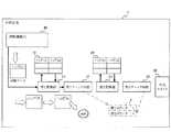
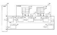
まず、図1に示すブロック図を参照しながら、中継装置(以下、本中継装置という)1の一実施形態の構成について説明する。なお、図1において実線矢印はデータの流れを示し、破線矢印はハードアクセスを示している。図1に示すように、本中継装置1は複数のポート(図示せず)を有し、各ポートに複数の装置を接続され、複数の装置間で送受信されるデータ(転送データ)を中継するものである。また、本中継装置1は第1ルーティングテーブル(第1変換テーブル)10,第1変換部11,第1チェック回路(第1検査部)12,第2ルーティングテーブル(第2変換テーブル)20,第2変換部21,第2チェック回路(第2検査部)22,外部コネクタ30,及び試験機能部40をそなえて構成されている。なお、試験機能部40は、試験装置として機能するものである。Hereinafter, embodiments of the present invention will be described with reference to the drawings.
[1] One Embodiment of the Present Invention [1-1] Outline of Functional Configuration of Relay Device as One Embodiment First, referring to the block diagram shown in FIG. 1, a relay device (hereinafter referred to as the present relay device). ) A configuration of one embodiment will be described. In FIG. 1, solid arrows indicate data flow, and broken arrows indicate hard access. As shown in FIG. 1, the relay device 1 has a plurality of ports (not shown), and a plurality of devices are connected to each port, and relays data (transfer data) transmitted and received between the plurality of devices. Is. The relay apparatus 1 includes a first routing table (first conversion table) 10, a
第1ルーティングテーブル10は、複数の装置のうち、一の装置から他の装置へ転送される転送データに含まれるヘッダ情報(以下、第1ヘッダ情報という)を、中継装置1内において当該転送データを転送元(送信元)の装置が接続されたポートから転送先(送信先)の装置が接続されたポートに転送するための中継用ヘッダ情報(即ち、中継装置1固有の情報)に対応付けて保持するものである。 The first routing table 10 includes header information (hereinafter referred to as first header information) included in transfer data transferred from one device to another device among a plurality of devices in the relay device 1. Is associated with relay header information (that is, information unique to the relay device 1) for transferring from the port to which the transfer source (transmission source) device is connected to the port to which the transfer destination (transmission destination) device is connected. To hold.
第1変換部11は、本中継装置1内でデータ転送を行なうために、第1ルーティングテーブル10に基づいて、転送データに含まれる第1ヘッダ情報を中継用ヘッダ情報に変換するものである。
具体的には、第1変換部11は、入力された転送データの第1ヘッダ情報の内容を検索キーとして第1ルーティングテーブル10を検索し、検索された第1ヘッダ情報に対応する中継用ヘッダ情報を当該転送データのヘッダ情報に変換する。The
Specifically, the
第1チェック回路12は、第1変換部11による変換結果が正常であるか否かを検査し、異常であると判断した変換結果に係る転送データを廃棄するものである。なお、第1チェック回路12は、変換結果が正常であると判断すると当該転送データを後段に送信する。
具体的には、第1チェック回路12は、第1変換部11によって変換処理が正常に実行されたか否か、及び、変換結果が正常であるか否かを、転送データのヘッダ情報が所定の範囲内のデータであるか否かに応じて判断する。The
Specifically, the
ここでは、第1チェック回路12は、変換結果である中継用ヘッダ情報が、予め設定された規定の範囲内のものであれば、第1変換部11による変換結果が正常であると判断する。一方、第1チェック回路12は、中継用ヘッダ情報が予め設定された規定の範囲内でなければ、第1変換部11による変換結果が異常であると判断する。
さらに、第1チェック回路12は、第1カウンタ13をそなえており、この第1カウンタ13は、第1チェック回路12によって廃棄された転送データの数をカウントするものである。従って、第1カウンタ13は廃棄カウンタとして機能する。Here, the
Further, the
第2ルーティングテーブル20は、中継用ヘッダ情報と、転送データを転送先である他の装置へ転送するためのヘッダ情報(以下、第2ヘッダ情報という)とを対応付けて保持するものである。
第2変換部21は、ネットワークにデータを送信するために、第2ルーティングテーブル20に基づいて、転送データに含まれる中継用ヘッダ情報を第2ヘッダ情報に変換するものである。The second routing table 20 holds relay header information and header information (hereinafter referred to as second header information) for transferring the transfer data to another device that is a transfer destination in association with each other.
The
具体的には、第2変換部21は、中継用ヘッダ情報の内容を検索キーとして第2ルーティングテーブル20を検索し、検索された中継用ヘッダ情報に対応する第2ヘッダ情報を当該転送データのヘッダ情報に変換する。
第2チェック回路22は、第2変換部21による変換結果が正常であるか否かを検査し、異常であると判断した変換結果に係る転送データを廃棄するものである。なお、第2チェック回路22は、変換結果が正常であると判断すると当該転送データを転送する。Specifically, the
The
具体的には、第2チェック回路22は、第2変換部21によって変換処理が正常に実行されたか否か、及び、変換結果が正常であるか否かを、転送データの第2ヘッダ情報が所定の範囲内のデータであるか否かに応じて判断する。
つまり、第2チェック回路22は、変換結果である第2ヘッダ情報が、予め設定された規定の範囲内のものであれば、第2変換部21による変換結果が正常であると判断する。一方、第2チェック回路22は、第2ヘッダ情報が予め設定された規定の範囲内でなければ、第2変換部21による変換結果が異常であると判断する。Specifically, the
That is, the
さらに、第2チェック回路22は、第2カウンタ23をそなえており、この第2カウンタ23は、第2チェック回路22によって廃棄された転送データの数をカウントするものである。第1カウンタ13と同様、第2カウンタ23は廃棄カウンタとして機能する。
外部コネクタ30は、転送データを外部に出力するためのものであり、ループバック機能を有しており、試験機能部40の後述するルータ制御部43に制御されて、第2チェック回路22を通過した転送データを試験機能部40にループバックする。Further, the
The
試験機能部40は、第1,2チェック回路12,22(以下、チェック回路ともいう)の試験を行なうものであり、試験スケジューラ41,データ決定部42,ルータ制御部43,データ送受信部44,及び判断部45をそなえて構成されている。
なお、試験機能部40の試験スケジューラ41,データ決定部42及びデータ送受信部44が、第1テスト転送データ入力部,第2テスト転送データ入力部,第3テスト転送データ入力部,第4テスト転送データ入力部として機能する。The
Note that the
また、試験機能部40の試験スケジューラ41及びルータ制御部43が、第1変換テーブル設定部及び第2変換テーブル設定部として機能する。
さらに、試験機能部40、即ち、試験スケジューラ41,データ決定部42,ルータ制御部43,データ送受信部44,及び判断部45は、本中継装置1の演算器(図示せず;例えば、CPU(Central Processing Unit))が、所定のアプリケーションプログラム(後述する試験プログラム)を実行することによって実現される。In addition, the
Further, the
試験スケジューラ41は、試験のスケジューリングを行ない、データ決定部42,ルータ制御部43及びデータ送受信部44を制御して第1,2チェック回路12,22の試験を行なうものである。
具体的には、試験スケジューラ41は、後述する図2,図3,図7,図9,及び図12に示す試験手順を実現すべく、データ決定部42,ルータ制御部43及びデータ送受信部44を制御するものである。The
Specifically, the
データ決定部42は、第1,2ルーティングテーブル10,20に設定すべきテーブルデータ、及び、本中継装置1に入力すべき試験データを決定するものである。
例えば、本中継装置1の試験を行なうオペレータが、送信すべき試験データとそれに対応するテーブルデータを予め与えておき、データ決定部42は、その内容にしたがってデータ決定を行なう。テーブルデータとしては、第1ルーティングテーブル10については第1ヘッダ情報と中継用ヘッダ情報との対、第2ルーティングテーブル20については中継用ヘッダ情報と第2ヘッダ情報との対が与えられる。The
For example, an operator who performs a test of the relay apparatus 1 gives in advance test data to be transmitted and corresponding table data, and the
データ決定部42が決定する試験データやテーブルデータの内容は、試験対象のチェック回路12,22や試験目的に応じて決定されるものであり、その詳細は後述する図5,図8,図10,及び図13等を参照しながら説明する。
ルータ制御部43は、第1ルーティングテーブル10,第1カウンタ13,第2ルーティングテーブル20,第2カウンタ23,及び外部コネクタ30の制御を行なうものである。The contents of the test data and the table data determined by the
The
具体的には、ルータ制御部43は、第1,2ルーティングテーブル10,20のそれぞれに対して、テーブルデータの登録/削除を行なう。
また、ルータ制御部43は、第1,2カウンタ13,23のそれぞれに対して、カウンタ値の読み込み/クリア(リセット)を行なう。
さらに、ルータ制御部43は、外部コネクタ30に対して、ループバック(折り返し)設定/解除を行なう。Specifically, the
Further, the
Further, the
データ送受信部44は、本中継装置1の主信号経路(図示せず)に対するデータの送受信を行なうものである。具体的には、本中継装置1において第1〜4テスト転送データが外部装置を接続されるポートから入力されたものとして扱われるようにするために、ポートに接続された入力経路より第1変換部11へ試験データを入力する。
また、データ送受信部44は、外部コネクタ30から出力されるべき転送データを受信する。この場合、外部コネクタ30はルータ制御部43によってループバック設定されていることが条件となる。The data transmission /
The data transmitter /
判断部45は、試験スケジューラ41が設定した試験スケジュールや、ルータ制御部43が読み込んだ第1,2カウンタ13,23の値や、データ送受信部44が外部コネクタ30を介して受信したデータに基づいて、チェック回路12,22のそれぞれが正常であるか否かを判断するものである。ここで、試験スケジュールは、データ決定部42によって決定されデータ送受信部44によって送信された試験データ及び、ルータ制御部43によって設定されたテーブルデータを含む。
なお、判断部45による具体的な処理内容については、後述する図3,図7,図9,及び図12等を参照しながら詳細に説明する。
そして、試験機能部40による試験結果や判断部45の判断結果は、本中継装置1の図示しない出力端子から外部に出力される。The
Note that the specific processing contents by the
Then, the test result by the
〔1−2〕一実施形態としての中継装置1の詳細な機能構成、及び、試験機能部40の試験手順について
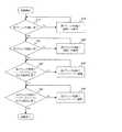
ここで、図2に示すフローチャート(ステップS10〜S40,S10´〜S40´)を参照しながら、本中継装置1の試験機能部40による試験手順の概要を説明する。試験機能部40は、まず、第1チェック回路12が正常であるか否かの検査を行なう(ステップS10)。[1-2] Detailed Functional Configuration of Relay Device 1 as One Embodiment and Test Procedure of
そして、第1チェック回路12が異常であった場合には(ステップS10のNoルート)、例えば、オペレータが第1チェック回路12の修理や交換等を行ない(ステップS10´)、再度、試験機能部40は第1チェック回路12の検査を行なう(ステップS10)。
一方、第1チェック回路12が正常であった場合には(ステップS10のYesルート)、試験機能部40は、第2チェック回路22が正常であるか否かの検査を行なう(ステップS20)。If the
On the other hand, when the
ここで、第2チェック回路22が異常であった場合には(ステップS20のNoルート)、例えば、オペレータが第2チェック回路22の修理や交換等を行ない(ステップS20´)、再度、試験機能部40は第2チェック回路22の検査を行なう(ステップS20)。
一方、第2チェック回路22が正常であった場合には(ステップS20のYesルート)、試験機能部40は、第1チェック回路12のバーストトラフィックに対する動作確認試験を行なう(ステップS30)。Here, if the
On the other hand, when the
そして、第1チェック回路12のバーストトラフィックに対する転送データの廃棄処理が異常であれば(ステップS30のNoルート)、例えば、オペレータが第1チェック回路12のタイミングマージンを調整し(ステップS30´)、再度、第1チェック回路12のバーストトラフィックに対する動作確認試験を行なう(ステップS30)。
一方、第1チェック回路12のバーストトラフィックに対する転送データの廃棄処理が正常であれば(ステップS30のYesルート)、試験機能部40は、第2チェック回路22のバーストトラフィックに対する動作確認試験を行なう(ステップS40)。If the transfer data discarding process for the burst traffic of the
On the other hand, if the transfer data discarding process for the burst traffic of the
ここで、第2チェック回路22のバーストトラフィックに対する転送データの廃棄処理が異常であれば(ステップS40のNoルート)、例えば、オペレータが第2チェック回路22のタイミングマージンを調整し(ステップS40´)、再度、第2チェック回路22のバーストトラフィックに対する動作確認試験を行なう(ステップS40)。
一方、第2チェック回路22のバーストトラフィックに対する転送データの廃棄処理が正常であれば(ステップS40のYesルート)、試験機能部40は処理を終了する。If the transfer data discarding process for the burst traffic of the
On the other hand, if the transfer data discarding process for the burst traffic of the
〔1−2−1〕第1チェック回路12の試験について
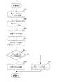
次に、図3に示すフローチャート(ステップS11〜S16)を参照しながら、試験機能部40の各構成要素41〜45の詳細な機能とともに、試験機能部40による第1チェック回路12の試験手順、つまり図2のステップS10の処理内容について詳細に説明する。[1-2-1] Test of
まず、試験スケジューラ41は、データ決定部42に第1ルーティングテーブル10に登録するテーブルデータとして、第1チェック回路12によって異常であると判断されるべき不正な中継用ヘッダ情報と第1ヘッダ情報との対応を決定させ、ルータ制御部43により当該テーブルデータを、第1ルーティングテーブル10に登録させる(ステップS11)。 First, the
このときのデータ決定部42及びルータ制御部43の処理手順を、図4に示すフローチャート(ステップS11a〜S11g)を参照しながら説明する。データ決定部42は、試験スケジューラ41から指示された構築データ種別を判断する(ステップS11a)。指示された構築データ種別が正常データであれば(ステップS11aの“正常データ”ルート)、データ決定部42は第1ヘッダ情報として検索キーワードであるヘッダ(a)を作成する(ステップS11b)。データ決定部42はさらに、中継用ヘッダ情報として、ヘッダ(a)再構築後のヘッダ(b)を作成する(ステップS11c)。 The processing procedure of the
そして、ルータ制御部43が、これらヘッダ(a)とヘッダ(b)との対を第1ルーティングテーブル10に登録して(ステップS11d)、処理を終了する。
一方、データ決定部42は、試験スケジューラ41から指示された構築データ種別が不正データであれば(ステップS11aの“不正データ”ルート)、第1ヘッダ情報として不正データの検索キーワードであるヘッダ(d)を作成する(ステップS11e)。データ決定部42はさらに、中継用ヘッダ情報として、ヘッダ(d)再構築後のヘッダ(e)を作成する(ステップS11f)。Then, the
On the other hand, if the construction data type instructed from the
続いて、ルータ制御部43が、これらヘッダ(d)とヘッダ(e)との対を第1ルーティングテーブル10に登録して(ステップS11d)、処理を終了する。
そして、図3の上記ステップS11において、例えば、図5に示すように、第1ルーティングテーブル10には、第1ヘッダ情報としてヘッダ(d)が登録され、中継用ヘッダ情報としてヘッダ(e)が登録される。Subsequently, the
In step S11 of FIG. 3, for example, as shown in FIG. 5, the header (d) is registered as the first header information in the first routing table 10, and the header (e) is registered as the relay header information. be registered.
このように、試験スケジューラ41,データ決定部42,及びルータ制御部43は、不正な中継用ヘッダ情報を第1ルーティングテーブル10に設定する、第1変換テーブル設定部として機能する。
続いて、試験スケジューラ41は、データ決定部42に第1ルーティングテーブル10に設定登録された不正な中継用ヘッダ情報に対応する第1ヘッダ情報を含むデータを試験データとして決定させ、決定された試験データをデータ送受信部44に第1変換部11へ送信させる(ステップS12)。ここでは、データ送受信部44は、試験スケジューラ41に制御されて、試験データを一つだけ第1変換部11に入力する。図5の例では、データ決定部42は第1ルーティングテーブル10に登録された、ヘッダ(d)を含むデータを試験データとして決定する。As described above, the
Subsequently, the
つまり、試験スケジューラ41,データ決定部42,及びデータ送受信部44は、不正な中継用ヘッダ情報に対応する第1ヘッダ情報を含む転送データを、試験データとして第1変換部11に入力する第1テスト転送データ入力部として機能する。
そして、試験スケジューラ41は、データ送受信部44による試験データの入力から所定時間経過後に、ルータ制御部43に第1チェック回路12の第1カウンタ13の値をリードさせる(ステップS13)。なお、本試験の開始時には、第1カウンタ13は試験スケジューラ41及びルータ制御部43によって値を0にリセットされている。That is, the
Then, the
次に、判断部45が、ルータ制御部43によってリードされた第1カウンタ13の値が、1以上であるか否か、即ち、第1チェック回路12によるデータ廃棄があるか否かを判断し、これにより、第1チェック回路12が正常であるか否かを判断する(ステップS14)。
つまり、判断部45は、試験スケジューラ41,データ決定部42,及びデータ送受信部44によって入力された試験データの数と、第1カウンタ13の値とに基づいて、第1チェック回路12が正常であるか否かを判断する。Next, the
That is, the
ここでは、試験データの数が1であるので、判断部45は、第1カウンタの値が1以上であるか否かだけを見ている。
そして、判断部45は、第1カウンタ13のカウンタ値が1以上であれば、即ち、試験データの数と第1カウンタ13の値とが一致すれば(ステップS14のYesルート)、第1チェック回路12が正常であると判断する(ステップS15)。つまり、第1チェック回路12が正常に動作していれば、不正な試験データが第1チェック回路12によって廃棄されるため、第1カウンタ13の値は1以上となる。なお、図5及び後述する図6において、二点鎖線で示す表2は、試験時の第1カウンタ13及び第2カウンタ23のそれぞれの値を示している。Here, since the number of test data is 1, the
If the counter value of the
一方、判断部45は、図6に示すように、第1カウンタ13のカウンタ値が0であれば、即ち、試験データの数と第1カウンタ13の値とが不一致であれば(ステップS14のNoルート)、第1チェック回路12が異常であると判断する。つまり、不正な試験データが送られたにも関わらず第1カウンタ13の値が0のままである場合、第1チェック回路12が不正な試験データを廃棄していないことを意味する。この場合、本中継装置1の外部の表示画面(図示せず)や本中継装置1がそなえる表示画面(図示せず)に、第1チェック回路12が異常である旨を表示し(ステップS16)、処理を終了する。 On the other hand, as shown in FIG. 6, if the counter value of the
このように、試験機能部40によれば、第1チェック回路12によって異常であると判断されるべき試験データを入力し、このときの第1カウンタ13の値に基づいて、第1チェック回路12が正常であるか否かを判断する。そのため、第1チェック回路12が正常であるか否かを確実に判断することができる。 Thus, according to the
〔1−2−2〕第2チェック回路22の試験について
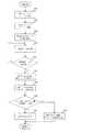
続いて、図7に示すフローチャート(ステップS21〜S27)を参照しながら、試験機能部40の各構成要素41〜45の詳細な機能とともに、試験機能部40による第2チェック回路22の試験手順、つまり図2のステップS20の処理内容について詳細に説明する。[1-2-2] Test of the
まず、試験スケジューラ41は、データ決定部42に第1ルーティングテーブル10に登録するテーブルデータとして、正常な中継用ヘッダ情報、即ち第1チェック回路12によって正常であると判断されるべきヘッダ情報と第1ヘッダ情報との対応を決定させる。そして試験スケジューラ41は、ルータ制御部43により当該テーブルデータを、第1ルーティングテーブル10に登録させる(ステップS21)。なお、データ決定部42及びルータ制御部43は、ステップS21及び後述するステップS22においても、上記図4に示した方法と同様もしくは略同様に処理を行なう。 First, the
ここでは、図8に示すように、データ決定部42は、第1ヘッダ情報としてのヘッダ(a)と、正常な中継用ヘッダ情報としてのヘッダ(b)との対を決定し、ルータ制御部43が、その対をテーブルデータとして第1ルーティングテーブル10に登録する。
さらに、試験スケジューラ41は、データ決定部42に、第2ルーティングテーブル20に登録するテーブルデータとして、第2チェック回路22によって異常であると判断されるべき不正な第2ヘッダ情報と、上記ステップS21において第1ルーティングテーブル10に登録された中継用ヘッダ情報との対応を決定させる。そして、試験スケジューラ41は、ルータ制御部43により対応が決定された不正なテーブルデータを、第2ルーティングテーブル20に登録させる(ステップS22)。Here, as shown in FIG. 8, the
Furthermore, the
つまり、図8に示すように、データ決定部42は、不正なデータである第2ヘッダ情報としてのヘッダ(f)と、中継用ヘッダ情報としてのヘッダ(b)との対を決定し、ルータ制御部43が、その対をテーブルデータとして第2ルーティングテーブル20に登録する。
このように、試験スケジューラ41,データ決定部42,及びルータ制御部43は、第2チェック回路22によって異常であると判断されるべき情報を含む不正な第2ヘッダ情報を、第2ルーティングテーブル20に設定する第2変換テーブル設定部として機能する。That is, as shown in FIG. 8, the
As described above, the
次に、試験スケジューラ41は、データ決定部42に、第2変換部21によって不正な第2ヘッダ情報(ヘッダ(f))に変換される第1ヘッダ情報(ヘッダ(a))を含むデータを試験データとして決定させる。そして、試験スケジューラ41はデータ送受信部44に、その試験データを第1変換部11へ送信させる(ステップS23)。ここでは、データ送受信部44は、試験スケジューラ41に制御されて、試験データを一つだけ第1変換部11に入力する。 Next, the
つまり、試験スケジューラ41,データ決定部42,及びデータ送受信部44は、第2変換部21によって不正な第2ヘッダ情報に変換される第1ヘッダ情報を含む転送データを、試験データとして第1変換部11に入力する第2テスト転送データ入力部として機能する。
これにより、図8に示すように、本中継装置1では、第1変換部11によって、第1ルーティングテーブル10に基づいてヘッダ(a)がヘッダ(b)に変換され、第1チェック回路12に入力される。ここでヘッダ(b)は正常なヘッダ情報であるので、第1チェック回路12により第1変換部11による変換結果が正常であると判断されて、後段の第2変換部21に入力される。そして、第2変換部21によって、第2ルーティングテーブル20に基づいてヘッダ(b)が不正なヘッダ(f)に変換され、第2チェック回路22で検査される。That is, the
As a result, as shown in FIG. 8, in the relay device 1, the
なお、第1チェック回路12は、図2のステップS10において正常であることが検査済みであるので、第2変換部21へのヘッダ(b)の入力は確実に行なわれる。
そして、試験スケジューラ41は、データ送受信部44による試験データの入力から所定時間経過後に、ルータ制御部43に第2チェック回路22の第2カウンタ23の値をリードさせる(ステップS24)。なお、本試験の開始時には、第1カウンタ13及び第2カウンタ23は、試験スケジューラ41及びルータ制御部43によって値を0にリセットされている。Since the
Then, the
続いて、判断部45は、ルータ制御部43によってリードされた第2カウンタ23の値が1以上であるか否か、即ち、第2チェック回路22によるデータ廃棄があるか否かを判断し、これにより、第2チェック回路22が正常であるか否かを判断する(ステップS25;第2判断ステップ)。
つまり、判断部45は、第2チェック回路22によって当該試験データに係る変換結果が廃棄されたか否かに応じて、第2チェック回路22が正常であるか否かを判断する。Subsequently, the
That is, the
ここでは、試験データの数が1であるので、判断部45は、第2カウンタ23の値が1以上であるか否かだけを見ている。
不正なヘッダ(f)を有する転送データが第2チェック回路22によって正常に廃棄されていれば、第2カウンタ23のカウンタ値は1以上となる。そのため、判断部45は、第2カウンタ23のカウンタ値が1以上であれば、即ち、試験データの数と第2カウンタ23の値とが一致すれば(ステップS25のYesルート)、第2チェック回路22が正常であると判断する(ステップS26)。Here, since the number of test data is 1, the
If transfer data having an illegal header (f) is normally discarded by the
一方、判断部45は、第2カウンタ23のカウンタ値が0であれば、即ち、試験データの数と第2カウンタ23の値とが不一致であれば(ステップS25のNoルート)、第2チェック回路22がヘッダ(f)の転送データを廃棄していないことを意味するため、第2チェック回路22が異常であると判断する。この場合、本中継装置1の外部の表示画面(図示せず)や本中継装置1がそなえる表示画面(図示せず)に第2チェック回路22が異常である旨を表示し(ステップS27)、処理を終了する。 On the other hand, if the counter value of the
このように、試験機能部40によれば、第1チェック回路12が正常であることを確認した後に、第2チェック回路22によって異常であると判断されるべき試験データを入力し、このときの第2カウンタ23の値に基づいて、第2チェック回路22が正常であるか否かを判断する。そのため、第2チェック回路22が正常であるか否かを確実に判断することができる。 As described above, according to the
〔1−2−3〕第1チェック回路12のバーストトラフィックに対する動作確認試験について
次に、図9に示すフローチャート(ステップS31〜S38)及び図10を参照しながら、試験機能部40の各構成要素41〜45の詳細な機能とともに、試験機能部40による第1チェック回路12のバーストトラフィックに対する動作確認の試験手順、つまり図2のステップS30の処理内容について詳細に説明する。[1-2-3] Operation Confirmation Test for Burst Traffic of
まず、試験スケジューラ41は、データ決定部42に第1ルーティングテーブル10に登録するテーブルデータとして、第1チェック回路12によって正常であると判断される通常の中継用ヘッダ情報(ヘッダ(b))と、第1ヘッダ情報(ヘッダ(a))との対を決定させる。また、試験スケジューラ41は、第1チェック回路12によって異常であると判断されるべき不正な中継用ヘッダ情報(ヘッダ(e))と第1ヘッダ情報(ヘッダ(d))との対を決定させる。そして、試験スケジューラ41は、ルータ制御部43により、それらのテーブルデータを、第1ルーティングテーブル10に登録させる(ステップS31)。なお、データ決定部42及びルータ制御部43は、ステップS31及び後述するステップS32においても上記図4に示した方法と同様もしくは略同様に処理を行なう。 First, the
このように、試験スケジューラ41,データ決定部42,及びルータ制御部43は、第1チェック回路12で異常であると判断されるべき不正な中継用ヘッダ情報を、第1ルーティングテーブル10に設定する第1変換テーブル設定部として機能する。
続いて、試験スケジューラ41は、データ決定部42に第2ルーティングテーブル20に登録するテーブルデータとして、上記ステップS31において登録した正常なテーブルデータに対応する中継用ヘッダ情報(ヘッダ(b))と、第2チェック回路22によって正常であると判断される通常の第2ヘッダ情報(ヘッダ(c))との対を決定させる。そして試験スケジューラ41は、ルータ制御部43により、そのテーブルデータを、第2ルーティングテーブル20に登録させる(ステップS32)。As described above, the
Subsequently, the
次に、試験スケジューラ41は、第1チェック回路12で異常と判断される中継用ヘッダ情報に対応する第1ヘッダ情報を選択し、不正な試験データとして決定させる。図11の例では、ヘッダ(d)が対応する。また、試験スケジューラ41は、第1チェック回路12で正常と判断される中継用ヘッダに対応する第1ヘッダ情報を選択し、正常な試験データとして決定させる。図11の例では、ヘッダ(a)が対応する。 Next, the
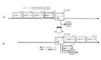
そして、試験スケジューラ41は、データ送受信部44に、不正な試験データと正常な試験データとを含む複数の試験データを、短時間のうちに連続的に第1変換部11に送信させる。即ち、データ送受信部44は、複数の試験データをバーストトラフィックとして連続的に第1変換部11に入力する(ステップS33)。
このとき、データ送受信部44は、不正な試験データの後には少なくとも一つ、ここでは2つの正常な試験データを連続して送信する。これにより、図11(a)に示すように、第1チェック回路12に対して異常データの直後に正常データが必ず入力されるようにする。これにより、第1チェック回路12のタイミングマージンの設定不良等により、第1チェック回路12が異常データを廃棄する際に後続の正常データも一緒に廃棄してしまうか否かを確実に試験することができる。Then, the
At this time, the data transmitting / receiving
また、データ送受信部44は、複数の試験データに不正な試験データを複数含めて送信することが好ましく、これによりバーストトラフィックに対する第1チェック回路12の動作確認をより確実に行なうことができる。
つまり、試験スケジューラ41,データ決定部42,及びデータ送受信部44は、不正な中継用ヘッダ情報に対応する第1ヘッダ情報を含む不正な試験データを含む、複数の試験データを連続的に第1変換部11に入力する第3テスト転送データ入力部として機能する。Further, the data transmitting / receiving
That is, the
そして、データ送受信部44による全試験データの送信が完了するまでは(ステップS34のNoルート)、試験データの送信処理(ステップS33)が行なわれる。そして、データ送受信部44による全試験データの送信が完了すると(ステップS34のYesルート)、試験スケジューラ41は、データ送受信部44による全試験データの入力から所定時間経過後に、ルータ制御部43に第1チェック回路12の第1カウンタ13の値をリードさせる(ステップS35)。 Then, until the transmission / reception of all test data by the data transmitting / receiving
なお、本試験の開始時には、第1カウンタ13及び第2カウンタ23は試験スケジューラ41及びルータ制御部43によって値を0にリセットされている。
次に、判断部45が、ルータ制御部43によってリードされた第1カウンタ13の値が、データ送受信部44によって入力された全ての試験データに含まれる不正な試験データの数と一致するか否かを判断する(ステップS36;第3判断ステップ)。Note that at the start of this test, the values of the
Next, the
つまり、判断部45は、第1カウンタ13の値と複数の試験データに含まれる不正な試験データの数とに基づいて、第1チェック回路12が正常であるか否かを判断する。なお、判断部45は、データ送受信部44から送信された不正な試験データの数を試験スケジューラ41またはデータ送受信部44から取得する。
ここで、判断部45は、第1カウンタ13の値と全試験データに含まれる不正な試験データの数とが一致すれば(ステップS36のYesルート)、図11(b)に示すように第1チェック回路12が異常データのみを廃棄する正常なもの、つまりタイミングマージンの設定が良好であると判断する(ステップS37)。つまり、第1チェック回路12は、上記図2のステップS10によって、異常データは必ず廃棄し、正常データは必ず通過させることは確認されているので、判断部45は、第1カウンタ13の値が不正な試験データの数と一致すれば、第1チェック回路12のタイミングマージンの設定が良好であると判断できる。That is, the
Here, if the value of the
一方、第1カウンタ13の値と不正な試験データの数とが不一致であれば(ステップS36のNoルート)、第1チェック回路12が異常であると判断して、本中継装置1の外部の表示画面(図示せず)や本中継装置1がそなえる表示画面(図示せず)に第1チェック回路12が異常である旨を表示し(ステップS38)、処理を終了する。
このように、試験機能部40は、上記図2のステップS10において第1チェック回路12が正常であることが確認された後に、第1チェック回路12によって異常であると判断されて廃棄されるべき不正な試験データを含む複数の試験データを、バーストトラフィックとして入力する。これにより、判断部45が、第1カウンタ13の数と不正な試験データの数とに基づいて第1チェック回路12が正常であるか否か、つまり、異常データの廃棄の際に、後続の正常データが異常データに引っ張られて誤って廃棄されていないかどうかを確実に判断でき、第1チェック回路12のタイミングマージンの設定が適切であるか否かを確実に判断できる。On the other hand, if the value of the
As described above, the
〔1−2−4〕第2チェック回路22のバーストトラフィックに対する動作確認試験について
次に、図12に示すフローチャート(ステップS41〜S48)及び図13を参照しながら、試験機能部40の各構成要素41〜45の詳細な機能とともに、試験機能部40による第2チェック回路22のバーストトラフィックに対する動作確認の試験手順、つまり図2のステップS40の処理内容について詳細に説明する。[1-2-4] Operation Confirmation Test for Burst Traffic of
まず、試験スケジューラ41は、データ決定部42に第1ルーティングテーブル10に登録するテーブルデータとして、第1チェック回路12によって正常であると判断される通常の中継用ヘッダ情報(ヘッダ(b))と第1ヘッダ情報(ヘッダ(a))との対を決定させる。また、試験スケジューラ41は、第1チェック回路12によって正常であると判断される通常の中継用ヘッダ情報(ヘッダ(h))と第1ヘッダ情報(ヘッダ(g))との対を決定させる。そして試験スケジューラ41は、ルータ制御部43により、決定されたそれらのテーブルデータを、第1ルーティングテーブル10に登録させる(ステップS41)。なお、データ決定部42及びルータ制御部43は、ステップS41及び後述するステップS42においても上記図4に示した方法と同様もしくは略同様に処理を行なう。 First, the
ここで、ヘッダ(h)は、第2ルーティングテーブル20に登録される、第2チェック回路22によって異常であると判断される第2ヘッダ情報(ヘッダ(i))に対応する中継用ヘッダ情報である。
続いて、試験スケジューラ41は、データ決定部42に第2ルーティングテーブル20に登録するテーブルデータとして、上記ステップS41において登録した中継用ヘッダ情報(ヘッダ(b))と、第2チェック回路22によって正常であると判断される通常の第2ヘッダ情報(ヘッダ(c))との対を決定させる。また、試験スケジューラ41は、上記ステップS41において登録した中継用ヘッダ情報(ヘッダ(h))と、第2チェック回路22によって異常であると判断されるべき不正な第2ヘッダ情報(ヘッダ(i))との対を決定させる。そして試験スケジューラ41は、ルータ制御部43により、決定されたそれらテーブルデータを、第2ルーティングテーブル20に登録させる(ステップS42)。Here, the header (h) is the header information for relay corresponding to the second header information (header (i)) registered in the second routing table 20 and determined to be abnormal by the
Subsequently, the
このように、試験スケジューラ41,データ決定部42,及びルータ制御部43は、第2チェック回路22で異常であると判断されるべき不正な第2ヘッダ情報に対応するテーブルデータを、第1ルーティングテーブル10及び第2ルーティングに設定する第2変換テーブル設定部として機能する。 As described above, the
次に、試験スケジューラ41は、第2チェック回路22によって異常と判断される第2ヘッダ情報に対応する第1のヘッダ情報を選択し、不正な試験データとして決定させる。図13の例では、ヘッダ(i)が第2チェック回路22によって異常と判定され、ヘッダ(i)に対応する第1ヘッダ情報はヘッダ(g)である。また、試験スケジューラ41は、第2チェック回路によって正常と判断される第2ヘッダ情報に対応する第1ヘッダ情報を選択し、これを正常な試験データとして決定させる。図13の例では、ヘッダ(c)が第2チェック回路22によって正常と判定され、ヘッダ(c)に対応する第1ヘッダ情報はヘッダ(a)である。 Next, the
そして、試験スケジューラ41は、データ送受信部44に不正な試験データと正常な試験データとを含む複数の試験データを、短時間のうちに連続的に第1変換部11に送信する。即ち、試験スケジューラ41は、複数の試験データをバーストトラフィックとして連続的に第1変換部11に入力する(ステップS43)。
このとき、データ送受信部44は、不正な試験データの後には少なくとも一つの正常な試験データを連続して送信することにより、第2チェック回路22に対して異常データの直後に正常データが必ず入力されるようにする。これにより、第2チェック回路22のタイミングマージンの設定不良等により、第2チェック回路22が異常データを廃棄する際に後続の正常データも一緒に廃棄してしまうか否かを確実に試験することができる。Then, the
At this time, the data transmission /
また、データ送受信部44は、複数の試験データに不正な試験データを複数含めて送信することが好ましく、これによりバーストトラフィックに対する第2チェック回路22の動作確認をより確実に行なうことができる。
つまり、試験スケジューラ41,データ決定部42,及びデータ送受信部44は、第2変換テーブル設定部によって、第2変換部21により不正な第2ヘッダ情報に変換される第1ヘッダ情報(ヘッダ(g))を含む不正な試験データを含む、複数のテスト転送データを連続的に第1変換部11に入力する第4テスト転送データ入力部として機能する。In addition, the data transmitting / receiving
In other words, the
そして、データ送受信部44による全試験データの送信が完了するまでは(ステップS44のNoルート)、試験データの送信処理(ステップS43)が行なわれる。そして、データ送受信部44による全試験データの送信が完了すると(ステップS44のYesルート)、試験スケジューラ41は、データ送受信部44による全試験データの入力から所定時間経過後に、ルータ制御部43に第2チェック回路22の第2カウンタ23の値をリードさせる(ステップS45)。
なお、本試験の開始時には、第1カウンタ13及び第2カウンタ23は試験スケジューラ41及びルータ制御部43によって値を0にリセットされている。Then, until the transmission / reception of all test data by the data transmitting / receiving
Note that at the start of this test, the values of the
次に、判断部45が、ルータ制御部43によってリードされた第2カウンタ23の値が、データ送受信部44によって入力された全ての試験データに含まれる不正な試験データ、即ちヘッダ(g)の試験データの数と一致するか否かを判断する(ステップS46)。 Next, the
つまり、判断部45は、第2カウンタ23の値と複数の試験データに含まれる不正な試験データの数とに基づいて、第2チェック回路22が正常であるか否かを判断する。なお、判断部45は、不正な試験データの数を試験スケジューラ41またはデータ送受信部44から取得する。
ここで、判断部45は、第2カウンタ23の値と全試験データに含まれる不正な試験データの数とが一致すれば(ステップS46のYesルート)、第2チェック回路22が異常データのみを廃棄する正常なものである、つまりタイミングマージンの設定が良好であると判断する(ステップS47)。つまり、第1チェック回路12及び第2チェック回路22は、上記図2のステップS10,S20によって、異常データは必ず廃棄し、正常データは必ず通過させることは確認されているので、判断部45は、第2カウンタ23の値が不正な試験データの数と一致すれば、第2チェック回路22のタイミングマージンの設定が良好であると判断できる。That is, the
Here, if the value of the
一方、第2カウンタ23の値と不正な試験データの数とが不一致であれば(ステップS46のNoルート)、第2チェック回路22が異常であると判断して、本中継装置1の外部の表示画面(図示せず)や本中継装置1がそなえる表示画面(図示せず)に第2チェック回路22が異常である旨を表示し(ステップS48)、処理を終了する。
このように、試験機能部40は、上記図2のステップS10,S20において第1チェック回路12及び第2チェック回路22が正常であることが確認された後に、第2チェック回路22によって異常であると判断されて廃棄されるべき不正な試験データを含む複数の試験データを、バーストトラフィックとして入力する。そして、判断部45が、第2カウンタ23の数と不正な試験データの数とに基づいて第2チェック回路22が正常であるか否か、つまり、異常データの廃棄の際に、後続の正常データが異常データに引っ張られて誤って廃棄されていないかどうかを確実に判断でき、第2チェック回路22のタイミングマージンの設定が適切であるか否かを確実に判断できる。On the other hand, if the value of the
As described above, the
〔1−3〕一実施形態としての中継装置1の効果について
このように、一実施形態としての中継装置1によれば、まず第1チェック回路12を検査すべく、試験機能部40の試験スケジューラ41,データ決定部42及びルータ制御部43が、第1チェック回路12で異常であると判断されるべき情報を第1ヘッダ情報として含む試験データを第1変換部11に入力する。そして、試験機能部40の判断部45が、入力された試験データの数と、第1カウンタ13の値とに基づいて、第1チェック回路12が正常であるか否かを判断する。このため、本中継装置1の第1チェック回路12が異常であるか否かを確実に判断することができる。つまり、異常がある第1チェック回路12を特定することができる。[1-3] Effect of Relay Device 1 as One Embodiment As described above, according to the relay device 1 as one embodiment, first, the test scheduler of the
このとき、試験機能部40の試験スケジューラ41,データ決定部42及びルータ制御部43が、第1チェック回路12で異常であると判断され廃棄されるべき不正な中継用ヘッダ情報を、第1ルーティングテーブル10に設定する。そして、設定された不正な中継用ヘッダ情報に対応する第1ヘッダ情報を含む転送データを、試験データとして第1変換部11に入力する。このため、本中継装置では第1チェック回路12の試験をより確実に行なうことができる。 At this time, the
なお、判断部45は、試験データの数と第1カウンタ13の値とが一致すれば、第1チェック回路12が正常であると判断する。一方、判断部45は、試験データの数と第1カウンタ13の値とが不一致であれば、第1チェック回路12が異常であると判断する。このため、第1チェック回路12が正常であるか否かをより確実に判断できる。
さらに、第1チェック回路12が正常であった場合には、第2チェック回路22を検査すべく、試験機能部40の試験スケジューラ41,データ決定部42及びルータ制御部43が、第2ルーティングテーブル20に第2チェック回路22によって異常であると判断されるべき情報を含む不正な第2ヘッダ情報を設定する。また、第2変換部21によって、不正な第2ヘッダ情報に変換される第1ヘッダ情報を含む試験データを、第1変換部11に入力する。そして、判断部45が、第2チェック回路22によって試験データに係る変換結果が廃棄されたか否かに応じて、第2チェック回路22が正常であるか否かを判断する。そのため、本中継装置1の第2チェック回路22が異常であるか否かを確実に判断することができる。つまり、異常がある第2チェック回路22を特定することができる。The
Furthermore, when the
このとき、判断部45が、第2チェック回路22によって試験データに係る変換結果が廃棄された場合には、第2チェック回路22が正常であると判断する。一方、判断部45は、第2チェック回路22によって試験データに係る変換結果が未廃棄である場合には、第2チェック回路22が異常であると判断する。より具体的には、判断部45は、第2カウンタ23の値と試験データの数とが一致すると、第2チェック回路22が正常であると判断する。一方、判断部45は、第2カウンタ23の値と試験データの数とが不一致であると、第2チェック回路22が異常であると判断する。このため、第2チェック回路22が正常であるか否かを確実に判断できる。 At this time, if the conversion result relating to the test data is discarded by the
また、第1チェック回路12及び第2チェック回路22が正常であった場合には、第1チェック回路12のバーストトラフィックに対する動作試験を実行すべく、試験機能部40の試験スケジューラ41,データ決定部42及びルータ制御部43が、第1チェック回路12により異常であると判断されるべき不正な中継用ヘッダ情報を、第1ルーティングテーブル10に設定する。そして、不正な中継用ヘッダ情報に対応する第1ヘッダ情報を含む第3テスト転送データを含む、複数のテスト転送データを連続的に第1変換部11に入力する。 When the
そして、判断部45が、第1カウンタ13の値に基づいて、第1チェック回路10が正常であるか否かを判断するので、第1チェック回路12のバーストトラフィックに対する動作確認を正確に実行できる。
つまり、第1チェック回路12のタイミングマージンの設定不良により、異常データを廃棄する際に、第1チェック回路12が後続の正常データを誤って廃棄してしまっているか否かを確実に検査することができる。And since the
That is, when the abnormal data is discarded due to a timing margin setting failure of the
このとき、判断部45が、第1カウンタ13の値と第1変換部11に入力された複数の試験データに含まれる不正な試験データの数とが一致すれば、第1チェック回路12が正常であると判断する。その一方、第1カウンタ13の値と不正な試験データの数とが不一致であれば、判断部45は第1チェック回路12が異常であると判断するので、第1チェック回路12のバーストトラフィックに対する動作確認をより正確に行なうことができる。 At this time, if the
さらに、第1チェック回路12及び第2チェック回路22が正常であった場合には、第2チェック回路22のバーストトラフィックに対する動作試験を実行すべく、試験機能部40の試験スケジューラ41,データ決定部42及びルータ制御部43が、第2ルーティングテーブル20に設定された不正な第2ヘッダ情報に第2変換部21により変換される第1ヘッダ情報を含む不正な試験データを含む、複数の試験データを連続的に第1変換部11に入力する。そして、判断部45が、第2カウンタ23の値に基づいて、第2チェック回路22が正常であるか否かを判断するので、第2チェック回路22のバーストトラフィックに対する動作確認を正確に実行できる。 Further, when the
つまり、第2チェック回路22のタイミングマージンの設定不良により、異常データを廃棄する際に、第2チェック回路22が後続の正常データを誤って廃棄してしまっているか否かを確実に検査することができる。
このとき、判断部45は、第2カウンタ23の値と複数の試験データに含まれる不正な試験データの数とが一致すれば、第2チェック回路22が正常であると判断する。一方、第2カウンタ23の値と不正な試験データの数とが不一致であれば、判断部45は第2チェック回路22が異常であると判断するので、第1チェック回路12のバーストトラフィックに対する動作確認をより正確に行なうことができる。That is, when the abnormal data is discarded due to the timing margin setting failure of the
At this time, the
〔2〕中継装置の変形例について
なお、本発明は上述した実施形態に限定されるものではなく、本発明の趣旨を逸脱しない範囲で種々変形して実施することができる。[2] Modification Examples of Relay Device The present invention is not limited to the above-described embodiment, and various modifications can be made without departing from the spirit of the present invention.
〔2−1〕第1変形例について
例えば、上述した実施形態では、中継装置1が試験機能部40をそなえて構成した例をあげて説明したが、本発明はこれに限定されるものではなく、図14に示すように、試験機能部40´が、中継装置1´の外部にそなえられていてもよい。
なお、図14において、既述の符号と同一の符号は同一の部分もしくは略同一の部分を示している。[2-1] First Modification For example, in the above-described embodiment, the relay apparatus 1 is described as including the
In FIG. 14, the same reference numerals as those described above indicate the same or substantially the same parts.
つまり、試験機能部40´の試験スケジューラ41,データ決定部42,ルータ制御部43,データ送受信部44,及び判断部45は、上述した一実施形態の試験機能部40と同一の機能を有するものである。
したがって、第1変形例としての試験機能部40´によっても、上述した一実施形態と同様の作用効果を得ることができる。That is, the
Therefore, the same function and effect as that of the above-described embodiment can be obtained also by the
〔2−2〕第2変形例について
また、上述した実施形態では、第1チェック回路12の試験を行なう際には、上記図3に示したように、試験スケジューラ41,データ決定部42,及びルータ制御部43が第1ルーティングテーブル10に不正なテーブルデータを登録し、試験スケジューラ41,データ決定部42,及びデータ送受信部44がその不正なテーブルデータに対応する試験データを第1変換部11に入力するように構成した。しかし、本発明はこれに限定されるものではなく、第1チェック回路12によって異常であると判断されて廃棄されるべき試験データを入力するために、試験スケジューラ41,データ決定部42,及びルータ制御部43が、第1ルーティングテーブル10に未登録のヘッダ情報を含む転送データを試験データとして、第1変換部11に入力するように構成してもよい。これによっても、判断部45は試験データの数と第1カウンタ13の値とに応じて第1チェック回路12が正常であるか否かを正確に判断できる。[2-2] Second Modification In the above-described embodiment, when the test of the
つまり、第1テスト転送データ入力部が第1ルーティングテーブル10に未登録のヘッダ情報を含む試験データを第1変換部11に入力することにより、第1変換部11は、第1ルーティングテーブル10に未登録のヘッダ情報を検索キーとして検索処理を行なうことになり、当然、検索処理を失敗する。すると、第1変換部11は、第1チェック回路12に対して検索処理を失敗したことを示すエラーステータスを送信する。そして、第1チェック回路12は、第1変換部11からエラーステータスを受け取ると、その検索処理を失敗したヘッダ情報を含む当該試験データを削除し、第1カウンタ13は値を一つカウントアップする。 That is, when the first test transfer data input unit inputs test data including unregistered header information in the first routing table 10 to the
したがって、上記図3のステップS12において、第1ルーティングテーブル10に未登録のヘッダ情報を含む試験データを第1変換部11に入力することにより、上記図3のステップS13〜S16と同様の処理を実行することができ、上述した実施形態と同様の作用効果を得ることができる。なお、この場合、ステップS11において、試験スケジューラ41,データ決定部42,及びルータ制御部43は、通常の正常なテーブルデータを第1ルーティングテーブル10に登録する。 Therefore, in step S12 of FIG. 3, the test data including the header information not registered in the first routing table 10 is input to the
〔2−3〕第3変形例について
また、上述した実施形態では、上記図7のステップS24,S25において、判断部45が第2カウンタ23の値に基づいて第2チェック回路22が正常であるか否かを判断した。しかし、本発明はこれに限定されるものではなく、例えば、試験スケジューラ41及びルータ制御部43が、外部コネクタ30を制御して、第2チェック回路22を通過して外部に出力されるべきデータをデータ送受信部44が受信できるように構成し、判断部45が、外部コネクタ30を介してデータ送受信部44が、第2チェック回路12を通過した転送データを受信したか否かに応じて、第2チェック回路22が正常であるか否かを判断するように構成してもよい。これによっても上述した実施形態と同様の作用効果を得ることができる。[2-3] Third Modification In the above-described embodiment, the
つまり、上記図2のステップS10において第1チェック回路12が正常であることが確認されているので、判断部45は、データ送受信部44が受信したデータの数と、入力された試験データの数とが一致すると、第2チェック回路22が正常であると判断することができる。
一方、判断部45は、データ送受信部44が受信したデータの数と、入力された試験データの数とが不一致であると、第2チェック回路22が異常であると判断することができ
る。That is, since it is confirmed that the
On the other hand, the
〔2−4〕第4変形例について
また、上述した実施形態では、第1チェック回路12のバーストトラフィックに対する動作確認、及び、第2チェック回路22のバーストトラフィックに対する動作確認において、判断部45は、各カウンタ13,23の値と不正な試験データの数とに基づいて判断を行なうように構成した。しかし、本発明はこれに限定されるものではない。例えば、各カウンタ13,23の値と第2チェック回路22を通過して外部コネクタ30から出力される転送データの数との合計が、複数の試験データの総数と一致するか否かに応じて、各チェック回路12,22が正常であるか否かを判断するように構成してもよい。[2-4] Fourth Modification In the above-described embodiment, in the operation check for the burst traffic of the
ここで、図15に示すフローチャート(ステップS31,S32,S32´,S33〜S35,S35´,S36´,S37,S38)を参照しながら、第1チェック回路12のバーストトラフィックに対する動作確認を行なう場合を例にあげて説明する。なお、図15において既述の符号と同一の符号は同一の部分もしくは略同一の部分を示しているので、その詳細な説明は省略する。 Here, referring to the flowchart shown in FIG. 15 (steps S31, S32, S32 ′, S33 to S35, S35 ′, S36 ′, S37, S38), the operation of the
まず、試験機能部40は、第1ルーティングテーブル10及び第2ルーティングテーブル20の登録(ステップS31,S32)を行なう。次に、試験スケジューラ41及びルータ制御部43が、第2チェック回路22を通過したデータを、外部コネクタ30を介してデータ送受信部44が受信できるようにすべく、外部コネクタ30のデータ折り返し設定を行なう(ステップS32´)。 First, the
続いて、データ送受信部44がすべての試験データの送信を行ない(ステップS33,S34)、ルータ制御部43が第1カウンタ13の値をリードする(ステップS35)。さらに、データ送受信部44が、外部コネクタ30から出力されて受信したデータの数を計上する(ステップS35´)。
そして、判断部45は、第1カウンタ13の値と第1チェック回路12及び第2チェック回路22を通過して本中継装置1の外部に出力される転送データの数との和と、複数の試験データの総数とが一致するか否かを判断する(ステップS36´)。ここで、これら和と総数とが一致すれば(ステップS36´のYesルート)、判断部45は第1チェック回路12が正常であると判断する。一方、和と総数とが不一致であれば(ステップS36´のNoルート)、判断部45は第1チェック回路12が異常であると判断する。Subsequently, the data transmitting / receiving
Then, the
このように、判断部45が、第1カウンタ13の値と外部に出力される転送データの数との和と、全試験データの数とに応じて、第1チェック回路12のバーストトラフィックに対する動作確認を行なうことができ、上述した実施形態と同様の作用効果を得ることができる。
また、試験機能部40は、第2チェック回路22のバーストトラフィックに対する動作確認においても、図16のフローチャート(ステップS41,S42,S42´,S43〜S45,S45´,S46´,S47,S48)に示すように、上述した第1チェック回路12の動作確認と同様に処理を行なうことにより、上述した実施形態と同様の作用効果を得ることができる。As described above, the
In addition, the
〔2−5〕第5変形例について
さらに、上述した実施形態では、第1チェック回路12のバーストトラフィックに対する動作確認と第2チェック回路22のバーストトラフィックに対する動作確認とを互いに独立して実行する場合を例にあげて説明した。しかし、本発明はこれに限定されるものではなく、これらの動作確認を同時に実行してもよい。[2-5] Fifth Modification Furthermore, in the above-described embodiment, the operation check for the burst traffic of the
つまり、図17に示すように、第1ルーティングテーブル10には、ヘッダ(a),(b)の対,ヘッダ(d),(e)の対,及びヘッダ(g),(h)の対を登録、つまり、上記図9のステップS31及び上記図12のステップS41を同時に実行する。また、第2ルーティングテーブル20には、ヘッダ(b),(c)の対,及びヘッダ(h),(i)の対を登録、つまり、上記図9のステップS32及び上記図12のステップS42を同時に実行する。そして、試験データとして、ヘッダ(a)を含む正常な試験データ,ヘッダ(d)を含む不正な試験データ,及びヘッダ(g)を含む不正な試験データを含む複数の試験データを送信、即ち上記図9のステップS33及び上記図12のステップS42を同時に実行する。 That is, as shown in FIG. 17, the first routing table 10 includes a pair of headers (a) and (b), a pair of headers (d) and (e), and a pair of headers (g) and (h). Is registered, that is, step S31 in FIG. 9 and step S41 in FIG. 12 are executed simultaneously. In the second routing table 20, a pair of headers (b) and (c) and a pair of headers (h) and (i) are registered, that is, step S32 in FIG. 9 and step S42 in FIG. Are executed at the same time. As test data, normal test data including the header (a), invalid test data including the header (d), and a plurality of test data including incorrect test data including the header (g) are transmitted, that is, Step S33 in FIG. 9 and step S42 in FIG. 12 are executed simultaneously.
このとき、試験スケジューラ41,データ決定部42,及びデータ送受信部44は、複数の試験データの並びは、ヘッダ(d)もしくはヘッダ(g)を含む不正な試験データの後には、正常な試験データが必ず続くようにする。
そして、上記図9のステップS35〜S38の処理と、上記図12のステップS45〜S48の処理とをそれぞれ実行することにより、第1チェック回路12のバーストトラフィックに対する動作確認と、第2チェック回路22のバーストトラフィックに対する動作確認とを並行して実行することができ、上述した実施形態と同様の作用効果を得ることができるとともに、試験時間を短縮することができる。At this time, the
Then, by performing the processing of steps S35 to S38 in FIG. 9 and the processing of steps S45 to S48 in FIG. 12, the operation check for the burst traffic of the
〔2−6〕その他
なお、上述した実施形態及び上述した第1〜5変形例は種々組み合わせて実行することができる。
また、上述した試験機能部40,40´、即ち、試験スケジューラ41,データ決定部42,ルータ制御部43,データ送受信部44,及び判断部45としての機能は、コンピュータ(CPU,情報処理装置,各種端末を含む)が所定のアプリケーションプログラム(試験プログラム)を実行することによって実現されてもよい。[2-6] Others The above-described embodiment and the above-described first to fifth modifications can be executed in various combinations.
Further, the functions as the
そのプログラムは、例えばフレキシブルディスク,CD(CD−ROM,CD−R,CD−RWなど),DVD(DVD−ROM,DVD−RAM,DVD−R,DVD−RW,DVD+R,DVD+RWなど)等のコンピュータ読取可能な記録媒体に記録された形態で提供される。この場合、コンピュータはその記録媒体から試験プログラムを読み取って内部記憶装置または外部記憶装置に転送し格納して用いる。また、そのプログラムを、例えば磁気ディスク,光ディスク,光磁気ディスク等の記憶装置(記録媒体)に記録しておき、その記憶装置から通信回線を介してコンピュータに提供するようにしてもよい。 The program is, for example, a computer such as a flexible disk, CD (CD-ROM, CD-R, CD-RW, etc.), DVD (DVD-ROM, DVD-RAM, DVD-R, DVD-RW, DVD + R, DVD + RW, etc.). It is provided in a form recorded on a readable recording medium. In this case, the computer reads the test program from the recording medium, transfers it to the internal storage device or the external storage device, and uses it. Further, the program may be recorded in a storage device (recording medium) such as a magnetic disk, an optical disk, or a magneto-optical disk, and provided from the storage device to a computer via a communication line.
ここで、コンピュータとは、ハードウェアとOS(オペレーティングシステム)とを含む概念であり、OSの制御の下で動作するハードウェアを意味している。また、OSが不要でアプリケーションプログラム単独でハードウェアを動作させるような場合には、そのハードウェア自体がコンピュータに相当する。ハードウェアは、少なくとも、CPU等のマイクロプロセッサと、記録媒体に記録されたコンピュータプログラムを読み取るための手段とをそなえている。 Here, the computer is a concept including hardware and an OS (operating system) and means hardware that operates under the control of the OS. Further, when the OS is unnecessary and the hardware is operated by the application program alone, the hardware itself corresponds to the computer. The hardware includes at least a microprocessor such as a CPU and means for reading a computer program recorded on a recording medium.
上記試験プログラムとしてのアプリケーションプログラムは、上述のようなコンピュータに、試験機能部40,40´(即ち、試験スケジューラ41,データ決定部42,ルータ制御部43,データ送受信部44,及び判断部45)としての機能を実現させるプログラムコードを含んでいる。また、その機能の一部は、アプリケーションプログラムではなくOSによって実現されてもよい。 The application program as the test program is stored in the
なお、本実施形態としての記録媒体としては、上述したフレキシブルディスク,CD,DVD,磁気ディスク,光ディスク,光磁気ディスクのほか、ICカード,ROMカートリッジ,磁気テープ,パンチカード,コンピュータの内部記憶装置(RAMやROMなどのメモリ),外部記憶装置等や、バーコードなどの符号が印刷された印刷物等の、コンピュータ読取可能な種々の媒体を利用することもできる。 In addition to the above-described flexible disk, CD, DVD, magnetic disk, optical disk, and magneto-optical disk, the recording medium according to this embodiment includes an IC card, ROM cartridge, magnetic tape, punch card, and internal storage device of a computer ( It is also possible to use various computer-readable media such as a memory such as a RAM or a ROM, an external storage device, or a printed matter on which a code such as a barcode is printed.
〔3〕付記
(付記1)
複数の装置を接続され、該複数の装置間で送受信されるデータを中継する中継装置であって、
複数の装置のうちの一の装置から他の装置へ転送される転送データに含まれる第1ヘッダ情報を、該中継装置内での中継用ヘッダ情報に対応付けて保持する第1変換テーブルと、
該第1変換テーブルに基づいて、該転送データに含まれる該第1ヘッダ情報を該中継用ヘッダ情報に変換する第1変換部と、
該第1変換部による変換結果が正常であるか否かを検査し、異常であると判断した該変換結果に係る転送データを廃棄する第1検査部と、
該中継用ヘッダ情報と、転送データを該他の装置へ転送するための第2ヘッダ情報とを対応付けて保持する第2変換テーブルと、
該第2変換テーブルに基づいて、該中継用ヘッダ情報を該第2ヘッダ情報に変換する第2変換部と、
該第2変換部による変換結果が正常であるか否かを検査し、異常であると判断した該変換結果に係る転送データを廃棄する第2検査部と、
該第1検査部によって廃棄された該転送データの数をカウントする第1カウンタと、
該第1検査部により異常であると判断されるべき情報を第1ヘッダ情報として含む第1テスト転送データを該第1変換部に入力する第1テスト転送データ入力部と、
該第1テスト転送データ入力部によって入力された該第1テスト転送データの数と、該第1カウンタの値とに基づいて、該第1検査部が正常であるか否かを判断する第1判断部とをそなえたことを特徴とする、中継装置。[3] Appendix (Appendix 1)
A relay device connected to a plurality of devices and relaying data transmitted and received between the plurality of devices,
A first conversion table for holding first header information included in transfer data transferred from one device of the plurality of devices to another device in association with relay header information in the relay device;
A first conversion unit that converts the first header information included in the transfer data into the relay header information based on the first conversion table;
A first inspection unit that inspects whether the conversion result by the first conversion unit is normal and discards the transfer data related to the conversion result determined to be abnormal;
A second conversion table that holds the relay header information and second header information for transferring the transfer data to the other device in association with each other;
A second conversion unit that converts the relay header information into the second header information based on the second conversion table;
A second inspection unit that inspects whether the conversion result by the second conversion unit is normal and discards transfer data related to the conversion result determined to be abnormal;
A first counter that counts the number of transfer data discarded by the first inspection unit;
A first test transfer data input unit for inputting first test transfer data including information to be determined as abnormal by the first inspection unit as first header information to the first conversion unit;
First determining whether or not the first checking unit is normal based on the number of the first test transfer data input by the first test transfer data input unit and the value of the first counter A relay device comprising a determination unit.
(付記2)
該第1検査部により異常であると判断されるべき不正な中継用ヘッダ情報を、該第1変換テーブルに設定する第1変換テーブル設定部をそなえ、
該第1テスト転送データ入力部が、不正な中継用ヘッダ情報に対応する該第1ヘッダ情報を含む転送データを該第1テスト転送データとして該第1変換部に入力することを特徴とする、付記1記載の中継装置。(Appendix 2)
A first conversion table setting unit configured to set in the first conversion table illegal relay header information to be determined to be abnormal by the first inspection unit;
The first test transfer data input unit inputs transfer data including the first header information corresponding to illegal relay header information to the first conversion unit as the first test transfer data. The relay device according to appendix 1.
(付記3)
該第1テスト転送データ入力部が、該第1変換テーブルに未登録のヘッダ情報を含む転送データを該第1テスト転送データとして該第1変換部に入力することを特徴とする、付記1記載の中継装置。
(付記4)
該第1判断部が、該第1テスト転送データの数と該第1カウンタの値とが一致すれば、該第1検査部が正常であると判断する一方、該第1テスト転送データの数と該第1カウンタの値とが不一致であれば、該第1検査部が異常であると判断することを特徴とする、付記1に記載の中継装置。(Appendix 3)
The first test transfer data input unit inputs transfer data including unregistered header information in the first conversion table to the first conversion unit as the first test transfer data. Relay device.
(Appendix 4)
If the number of the first test transfer data matches the value of the first counter, the first determination unit determines that the first check unit is normal, while the number of the first test transfer data If the value of the first counter does not match the value of the first counter, it is determined that the first inspection unit is abnormal.
(付記5)
該第2変換テーブルに該第2検査部によって異常であると判断されるべき情報を含む不正な第2ヘッダ情報を設定する第2変換テーブル設定部と、
該第2変換部によって該不正な第2ヘッダ情報に変換される該第1ヘッダ情報を含む第2テスト転送データを該第1変換部に入力する第2テスト転送データ入力部と、
該第2検査部によって該第2テスト転送データに係る変換結果が廃棄されたか否かに応じて、該第2検査部が正常であるか否かを判断する第2判断部とをそなえたことを特徴とする、付記1に記載の中継装置。(Appendix 5)
A second conversion table setting unit for setting incorrect second header information including information to be determined to be abnormal by the second inspection unit in the second conversion table;
A second test transfer data input unit for inputting second test transfer data including the first header information to be converted into the illegal second header information by the second conversion unit to the first conversion unit;
A second determination unit for determining whether or not the second inspection unit is normal according to whether or not the conversion result relating to the second test transfer data has been discarded by the second inspection unit; The relay device according to appendix 1, characterized by:
(付記6)
該第2判断部が、該第2検査部によって該第2テストデータに係る変換結果が廃棄された場合には、該第2検査部が正常であると判断する一方、該第2検査部によって該第2テストデータに係る変換結果が未廃棄である場合には、該第2検査部が異常であると判断することを特徴とする、付記5記載の中継装置。(Appendix 6)
When the second inspection unit discards the conversion result related to the second test data, the second determination unit determines that the second inspection unit is normal, while the second inspection unit 6. The relay apparatus according to appendix 5, wherein the second inspection unit determines that the conversion is abnormal when the conversion result related to the second test data is not discarded.
(付記7)
該第2検査部によって廃棄された該転送データの数をカウントする第2カウンタをそなえ、
該第2判断部が、該第2カウンタの値と該第2テスト転送データ入力部によって入力された該第2テスト転送データの数とが一致すると、該第2検査部が正常であると判断する一方、該第2カウンタの値と該第2テスト転送データの数とが不一致であると、該第2検査部が異常であると判断することを特徴とする、付記5記載の中継装置。(Appendix 7)
A second counter for counting the number of transfer data discarded by the second inspection unit;
The second determination unit determines that the second inspection unit is normal when the value of the second counter matches the number of the second test transfer data input by the second test transfer data input unit. On the other hand, if the value of the second counter and the number of the second test transfer data do not match, the relay apparatus according to appendix 5, wherein the second inspection unit determines that it is abnormal.
(付記8)
該第1検査部により異常であると判断されるべき不正な中継用ヘッダ情報を、該第1変換テーブルに設定する第1変換テーブル設定部と、
該不正な中継用ヘッダ情報に対応する該第1ヘッダ情報を含む第3テスト転送データを含む、複数のテスト転送データを連続的に該第1変換部に入力する第3テスト転送データ入力部と、
該第1カウンタの値に基づいて、該第1検査部が正常であるか否かを判断する第3判断部とをそなえたことを特徴とする、付記5に記載の中継装置。(Appendix 8)
A first conversion table setting unit that sets, in the first conversion table, incorrect relay header information to be determined to be abnormal by the first inspection unit;
A third test transfer data input unit for continuously inputting a plurality of test transfer data to the first conversion unit, including third test transfer data including the first header information corresponding to the illegal relay header information; ,
The relay apparatus according to appendix 5, further comprising a third determination unit that determines whether or not the first inspection unit is normal based on the value of the first counter.
(付記9)
該第3判断部が、該第1カウンタの値と該第3テスト転送データ入力部によって該第1変換部に入力された該複数のテスト転送データに含まれる該第3テスト転送データの数とが一致すれば、該第1検査部が正常であると判断する一方、該第1カウンタの値と該第3テスト転送データの数とが不一致であれば、該第1検査部が異常であると判断することを特徴とする、付記8記載の中継装置。(Appendix 9)
The third determination unit includes a value of the first counter and the number of the third test transfer data included in the plurality of test transfer data input to the first conversion unit by the third test transfer data input unit; If the two values match, it is determined that the first checking unit is normal. On the other hand, if the value of the first counter does not match the number of the third test transfer data, the first checking unit is abnormal. The relay device according to appendix 8, wherein the relay device is determined.
(付記10)
該第2検査部によって廃棄された該転送データの数をカウントする第3カウンタと、
該第2変換テーブル設定部によって該第2変換テーブルに設定された該不正な第2ヘッダ情報に該第2変換部により変換される該第1ヘッダ情報を含む第4テスト転送データを含む、複数のテスト転送データを連続的に該第1変換部に入力する第4テスト転送データ入力部と、
該第3カウンタの値に基づいて、該第2検査部が正常であるか否かを判断する第4判断部とをそなえたことを特徴とする、付記5に記載の中継装置。(Appendix 10)
A third counter for counting the number of transfer data discarded by the second inspection unit;
A plurality of fourth test transfer data including the first header information converted by the second conversion unit to the illegal second header information set in the second conversion table by the second conversion table setting unit; A fourth test transfer data input unit for continuously inputting the test transfer data to the first conversion unit;
The relay apparatus according to appendix 5, further comprising a fourth determination unit that determines whether or not the second inspection unit is normal based on a value of the third counter.
(付記11)
複数の装置を接続され、該複数の装置間で送受信されるデータを中継する中継装置であって、複数の装置のうちの一の装置から他の装置へ転送される転送データに含まれる第1ヘッダ情報を該中継装置内での中継用ヘッダ情報に対応付けて保持する第1変換テーブルと、該第1変換テーブルに基づいて該転送データに含まれる該第1ヘッダ情報を該中継用ヘッダ情報に変換する第1変換部と、該第1変換部による変換結果が正常であるか否かを検査し異常であると判断した該変換結果に係る転送データを廃棄する第1検査部と、該第1検査部によって廃棄された該転送データの数をカウントする第1カウンタと、該中継用ヘッダ情報と転送データを該他の装置へ転送するための第2ヘッダ情報とを対応付けて保持する第2変換テーブルと、該第2変換テーブルに基づいて該中継用ヘッダ情報を該第2ヘッダ情報に変換する第2変換部と、該第2変換部による変換結果が正常であるか否かを検査し異常であると判断した該変換結果に係る転送データを廃棄する第2検査部とを有する該中継装置に係る試験装置であって、
該第1検査部により異常であると判断されるべき情報を第1ヘッダ情報として含む第1テスト転送データを該第1変換部に入力する第1テスト転送データ入力部と、
該第1テスト転送データ入力部によって入力された該第1テスト転送データの数と、該第1カウンタの値とに基づいて、該第1検査部が正常であるか否かを判断する第1判断部とをそなえたことを特徴とする、試験装置。(Appendix 11)
A relay device that is connected to a plurality of devices and relays data transmitted / received between the plurality of devices, and is included in transfer data that is transferred from one device of the plurality of devices to another device. A first conversion table that holds header information in association with relay header information in the relay apparatus, and the first header information included in the transfer data based on the first conversion table is the relay header information A first conversion unit for converting to the first conversion unit, a first inspection unit for checking whether the conversion result by the first conversion unit is normal and determining that the conversion result is abnormal, A first counter that counts the number of transfer data discarded by the first check unit, and the relay header information and second header information for transferring the transfer data to the other device are stored in association with each other. A second conversion table, and A second conversion unit that converts the relay header information into the second header information based on the two conversion tables, and whether the conversion result by the second conversion unit is normal or not is determined to be abnormal. A test apparatus according to the relay apparatus having a second inspection unit that discards the transfer data according to the conversion result,
A first test transfer data input unit for inputting first test transfer data including information to be determined as abnormal by the first inspection unit as first header information to the first conversion unit;
First determining whether or not the first checking unit is normal based on the number of the first test transfer data input by the first test transfer data input unit and the value of the first counter A test apparatus comprising a determination unit.
(付記12)
該第2変換テーブルに該第2検査部によって異常であると判断されるべき情報を含む不正な第2ヘッダ情報を設定する第2変換テーブル設定部と、
該第2変換部によって該不正な第2ヘッダ情報に変換される該第1ヘッダ情報を含む第2テスト転送データを該第1変換部に入力する第2テスト転送データ入力部と、
該第2検査部によって該第2テスト転送データに係る変換結果が廃棄されたか否かに応じて、該第2検査部が正常であるか否かを判断する第2判断部とをそなえたことを特徴とする、付記11記載の試験装置。(Appendix 12)
A second conversion table setting unit for setting incorrect second header information including information to be determined to be abnormal by the second inspection unit in the second conversion table;
A second test transfer data input unit for inputting second test transfer data including the first header information to be converted into the illegal second header information by the second conversion unit to the first conversion unit;
A second determination unit for determining whether or not the second inspection unit is normal according to whether or not the conversion result relating to the second test transfer data has been discarded by the second inspection unit; The test apparatus according to
(付記13)
該第1検査部により異常であると判断されるべき不正な中継用ヘッダ情報を、該第1変換テーブルに設定する第1変換テーブル設定部と、
該不正な中継用ヘッダ情報に対応する該第1ヘッダ情報を含む第3テスト転送データを含む、複数のテスト転送データを連続的に該第1変換部に入力する第3テスト転送データ入力部と、
該第1カウンタの値と該第3テスト転送データ入力部によって該第1変換部に入力された該複数のテスト転送データに含まれる該第3テスト転送データの数とに基づいて、該第1検査部が正常であるか否かを判断する第3判断部とをそなえたことを特徴とする、付記12記載の試験装置。(Appendix 13)
A first conversion table setting unit that sets, in the first conversion table, incorrect relay header information to be determined to be abnormal by the first inspection unit;
A third test transfer data input unit for continuously inputting a plurality of test transfer data to the first conversion unit, including third test transfer data including the first header information corresponding to the illegal relay header information; ,
Based on the value of the first counter and the number of the third test transfer data included in the plurality of test transfer data input to the first conversion unit by the third test transfer data input unit. The test apparatus according to
(付記14)
該第2変換テーブル設定部によって該第2変換テーブルに設定された該不正な第2ヘッダ情報に該第2変換部により変換される該第1ヘッダ情報を含む第4テスト転送データを含む、複数のテスト転送データを連続的に該第1変換部に入力する第4テスト転送データ入力部と、
該第2カウンタの値と該第4テスト転送データ入力部によって該第1変換部に入力された該複数のテスト転送データに含まれる該第4テスト転送データの数とに基づいて、該第2検査部が正常であるか否かを判断する第4判断部とをそなえたことを特徴とする、付記12記載の試験装置。(Appendix 14)
A plurality of fourth test transfer data including the first header information converted by the second conversion unit to the illegal second header information set in the second conversion table by the second conversion table setting unit; A fourth test transfer data input unit for continuously inputting the test transfer data to the first conversion unit;
Based on the value of the second counter and the number of the fourth test transfer data included in the plurality of test transfer data input to the first conversion unit by the fourth test transfer data input unit, the second test transfer data The test apparatus according to
(付記15)
複数の装置を接続され、該複数の装置間で送受信されるデータを中継する中継装置であって、複数の装置のうちの一の装置から他の装置へ転送される転送データに含まれる第1ヘッダ情報を該中継装置内での中継用ヘッダ情報に対応付けて保持する第1変換テーブルと、該第1変換テーブルに基づいて該転送データに含まれる該第1ヘッダ情報を該中継用ヘッダ情報に変換する第1変換部と、該第1変換部による変換結果が正常であるか否かを検査し異常であると判断した該変換結果に係る転送データを廃棄する第1検査部と、該第1検査部によって廃棄された該転送データの数をカウントする第1カウンタと、該中継用ヘッダ情報と転送データを該他の装置へ転送するための第2ヘッダ情報とを対応付けて保持する第2変換テーブルと、該第2変換テーブルに基づいて該中継用ヘッダ情報を該第2ヘッダ情報に変換する第2変換部と、該第2変換部による変換結果が正常であるか否かを検査し異常であると判断した該変換結果に係る転送データを廃棄する第2検査部とを有する該中継装置に係る試験方法であって、
該第1検査部により異常であると判断されるべき情報を第1ヘッダ情報として含む第1テスト転送データを該第1変換部に入力する第1テスト転送データ入力ステップ、
該第1テスト転送データ入力ステップにおいて入力された該第1テスト転送データの数と、該第1カウンタの値とに基づいて、該第1検査部が正常であるか否かを判断する第1判断ステップ、
該第1判断ステップにおいて該第1検査部が正常であると判断された場合に、該第2変換テーブルに該第2検査部によって異常であると判断されるべき情報を含む不正な第2ヘッダ情報を設定する第2変換テーブル設定ステップ、
該第2変換部によって該不正な第2ヘッダ情報に変換される該第1ヘッダ情報を含む第2テスト転送データを該第1変換部に入力する第2テスト転送データ入力ステップ、及び、
該第2検査部によって該第2テスト転送データに係る変換結果が廃棄されたか否かに応じて、該第2検査部が正常であるか否かを判断する第2判断ステップを含んでいることを特徴とする、試験方法。(Appendix 15)
A relay device that is connected to a plurality of devices and relays data transmitted / received between the plurality of devices, and is included in transfer data that is transferred from one device of the plurality of devices to another device. A first conversion table that holds header information in association with relay header information in the relay apparatus, and the first header information included in the transfer data based on the first conversion table is the relay header information A first conversion unit for converting to the first conversion unit, a first inspection unit for checking whether the conversion result by the first conversion unit is normal and determining that the conversion result is abnormal, A first counter that counts the number of transfer data discarded by the first check unit, and the relay header information and second header information for transferring the transfer data to the other device are stored in association with each other. A second conversion table, and A second conversion unit that converts the relay header information into the second header information based on the two conversion tables, and whether the conversion result by the second conversion unit is normal or not is determined to be abnormal. A test method according to the relay device including a second inspection unit that discards transfer data according to the conversion result,
A first test transfer data input step for inputting first test transfer data including information to be determined to be abnormal by the first inspection unit as first header information to the first conversion unit;
A first determination is made as to whether or not the first inspection unit is normal based on the number of the first test transfer data input in the first test transfer data input step and the value of the first counter. Judgment step,
An illegal second header including information to be determined to be abnormal by the second inspection unit in the second conversion table when the first inspection unit is determined to be normal in the first determination step A second conversion table setting step for setting information;
A second test transfer data input step for inputting second test transfer data including the first header information to be converted into the illegal second header information by the second conversion unit into the first conversion unit; and
Including a second determination step of determining whether or not the second inspection unit is normal according to whether or not the conversion result relating to the second test transfer data has been discarded by the second inspection unit. A test method characterized by
(付記16)
該第2判断ステップにおいて該第2検査部が正常であると判断された場合に、該第1検査部により異常であると判断されるべき不正な中継用ヘッダ情報を、該第1変換テーブルに設定する第1変換テーブル設定ステップ、
該不正な中継用ヘッダ情報に対応する該第1ヘッダ情報を含む第3テスト転送データを含む、複数のテスト転送データを連続的に該第1変換部に入力する第3テスト転送データ入力ステップ、及び、
該第1カウンタの値と該第3テスト転送データ入力ステップにおいて該第1変換部に入力された該複数のテスト転送データに含まれる該第3テスト転送データの数とに基づいて、該第1検査部が正常であるか否かを判断する第3判断ステップを含んでいることを特徴とする、付記15記載の試験方法。(Appendix 16)
In the second determination step, when it is determined that the second inspection unit is normal, invalid relay header information to be determined to be abnormal by the first inspection unit is stored in the first conversion table. A first conversion table setting step to be set;
A third test transfer data input step for continuously inputting a plurality of test transfer data to the first conversion unit, including the third test transfer data including the first header information corresponding to the illegal relay header information; as well as,
Based on the value of the first counter and the number of third test transfer data included in the plurality of test transfer data input to the first conversion unit in the third test transfer data input step, The test method according to appendix 15, further comprising a third determination step of determining whether or not the inspection unit is normal.
(付記17)
該第2判断ステップにおいて該第2検査部が正常であると判断された場合に、該第2変換テーブル設定ステップにおいて該第2変換テーブルに設定された該不正な第2ヘッダ情報に該第2変換部により変換される該第1ヘッダ情報を含む第4テスト転送データを含む、複数のテスト転送データを連続的に該第1変換部に入力する第4テスト転送データ入力ステップ、及び、
該第3カウンタの値と該第4テスト転送データ入力ステップにおいて該第1変換部に入力された該複数のテスト転送データに含まれる該第4テスト転送データの数とに基づいて、該第2検査部が正常であるか否かを判断する第4判断ステップを含んでいることを特徴とする、付記15記載の試験方法。(Appendix 17)
When it is determined in the second determination step that the second inspection unit is normal, the second second header information set in the second conversion table in the second conversion table setting step includes the second A fourth test transfer data input step for continuously inputting a plurality of test transfer data including the fourth test transfer data including the first header information to be converted by the conversion unit to the first conversion unit; and
Based on the value of the third counter and the number of the fourth test transfer data included in the plurality of test transfer data input to the first conversion unit in the fourth test transfer data input step, The test method according to appendix 15, further comprising a fourth determination step of determining whether or not the inspection unit is normal.
(付記18)
複数の装置を接続され、該複数の装置間で送受信されるデータを中継する中継装置であって、複数の装置のうちの一の装置から他の装置へ転送される転送データに含まれる第1ヘッダ情報を該中継装置内での中継用ヘッダ情報に対応付けて保持する第1変換テーブルと、該第1変換テーブルに基づいて該転送データに含まれる該第1ヘッダ情報を該中継用ヘッダ情報に変換する第1変換部と、該第1変換部による変換結果が正常であるか否かを検査し異常であると判断した該変換結果に係る転送データを廃棄する第1検査部と、該第1検査部によって廃棄された該転送データの数をカウントする第1カウンタと、該中継用ヘッダ情報と転送データを該他の装置へ転送するための第2ヘッダ情報とを対応付けて保持する第2変換テーブルと、該第2変換テーブルに基づいて該中継用ヘッダ情報を該第2ヘッダ情報に変換する第2変換部と、該第2変換部による変換結果が正常であるか否かを検査し異常であると判断した該変換結果に係る転送データを廃棄する第2検査部とを有する該中継装置に係る試験を行なう機能を、コンピュータに実現させるための試験プログラムであって、
該第1検査部により異常であると判断されるべき情報を第1ヘッダ情報として含む第1テスト転送データを該第1変換部に入力する第1テスト転送データ入力部、及び、
該第1テスト転送データ入力部によって入力された該第1テスト転送データの数と、該第1カウンタの値とに基づいて、該第1検査部が正常であるか否かを判断する第1判断部として、該コンピュータを機能させることを特徴とする、試験プログラム。(Appendix 18)
A relay device that is connected to a plurality of devices and relays data transmitted / received between the plurality of devices, and is included in transfer data that is transferred from one device of the plurality of devices to another device. A first conversion table that holds header information in association with relay header information in the relay apparatus, and the first header information included in the transfer data based on the first conversion table is the relay header information A first conversion unit for converting to the first conversion unit, a first inspection unit for checking whether the conversion result by the first conversion unit is normal and determining that the conversion result is abnormal, A first counter that counts the number of transfer data discarded by the first check unit, and the relay header information and second header information for transferring the transfer data to the other device are stored in association with each other. A second conversion table, and A second conversion unit that converts the relay header information into the second header information based on the two conversion tables, and whether the conversion result by the second conversion unit is normal or not is determined to be abnormal. A test program for causing a computer to realize a function of performing a test related to the relay device having a second inspection unit that discards transfer data related to the conversion result,
A first test transfer data input unit for inputting first test transfer data including information to be determined as abnormal by the first inspection unit as first header information to the first conversion unit; and
First determining whether or not the first checking unit is normal based on the number of the first test transfer data input by the first test transfer data input unit and the value of the first counter A test program for causing the computer to function as a determination unit.
(付記19)
複数の装置が接続され、該複数の装置間で送受信されるデータを中継する中継装置であって、
複数の装置のうち、一の装置から他の装置へ転送される転送データに含まれる第1ヘッダ情報を、第2ヘッダ情報に対応付けて保持する第1変換テーブルと、
前記第1変換テーブルに基づいて、前記転送データに含まれる前記第1ヘッダ情報を前記第2ヘッダ情報に変換する第1変換部と、
前記第1変換部による変換結果が正常であるか否かを検査し、異常であると判断した転送データを廃棄する第1検査部と、
前記第1検査部により異常であると判断されるべき第2ヘッダ情報を、第1ヘッダ情報と対応付けて前記第1変換テーブルに設定する設定部と、
前記異常であると判断される第2ヘッダ情報に対応する第1ヘッダ情報を含む第1試験データを、前記第1変換部に入力する入力部と、
前記第1検査部によって、前記第1試験データに係る変換結果が廃棄されたか否かに応じて、前記第1検査部が正常であるか否かを判断する判断部とをそなえたことを特徴とする中継装置。(Appendix 19)
A relay device that connects a plurality of devices and relays data transmitted and received between the devices,
A first conversion table that holds first header information included in transfer data transferred from one device to another device among a plurality of devices in association with second header information;
A first conversion unit that converts the first header information included in the transfer data into the second header information based on the first conversion table;
Inspecting whether or not the conversion result by the first converter is normal, and discarding the transfer data determined to be abnormal,
A setting unit that sets second header information to be determined to be abnormal by the first inspection unit in the first conversion table in association with the first header information;
An input unit for inputting first test data including first header information corresponding to second header information determined to be abnormal to the first conversion unit;
The first inspection unit includes a determination unit that determines whether or not the first inspection unit is normal according to whether or not the conversion result relating to the first test data has been discarded. A relay device.
(付記20)
前記中継装置において、
前記入力部は、前記第1試験データに、前記第1検査部により正常と判断されるべき第2ヘッダ情報に対応した第1ヘッダ情報を含む第2試験データを混在させて、前記第1検査部に入力し、
前記判断部は、前記第1試験データおよび前記第2試験データに係る変換結果の廃棄状況に応じて、前記第1検査部が正常であるか否かを判断することを特徴とする、付記19に記載の中継装置。(Appendix 20)
In the relay device,
The input unit mixes the first test data with second test data including first header information corresponding to second header information to be determined to be normal by the first test unit, and the first test data. Enter
Supplementary note 19 wherein the determination unit determines whether or not the first inspection unit is normal according to a discard status of the conversion result relating to the first test data and the second test data. The relay device described in 1.
(付記21)
前記中継装置はさらに、
前記第2ヘッダ情報と、転送データを前記他の装置へ転送するための第3ヘッダ情報とを対応付けて保持する第2変換テーブルと、
前記第2変換テーブルに基づいて、前記第2ヘッダ情報を前記第3ヘッダ情報に変換する第2変換部と、
前記第2変換部による変換結果が正常であるか否かを検査し、異常であると判断した転送データを廃棄する第2検査部と、
前記第1検査部によって正常であると判断されるべき第2ヘッダ情報に対応するとともに、前記第2検査部によって異常であると判断されるべき第3ヘッダ情報を、第2ヘッダ情報と対応付けて第2変換テーブルに設定する第2設定部と、を備えるとともに、
前記入力部は、前記第2変換部によって異常であると判断される第3ヘッダ情報に対応する第1ヘッダ情報を含む第3試験データを前記第1変換部に入力し、
前記判断部は、前記第2検査部によって前記第2テスト転送データに係る変換結果が廃棄されたか否かに応じて、前記第2検査部が正常であるか否かを判断することを特徴とする、付記19に記載の中継装置。(Appendix 21)
The relay device further includes
A second conversion table that holds the second header information in association with third header information for transferring transfer data to the other device;
A second conversion unit that converts the second header information into the third header information based on the second conversion table;
A second inspection unit that inspects whether the conversion result by the second conversion unit is normal and discards the transfer data determined to be abnormal;
Corresponding to the second header information to be determined to be normal by the first inspection unit, and corresponding to the second header information, the third header information to be determined to be abnormal by the second inspection unit And a second setting unit that sets the second conversion table.
The input unit inputs third test data including first header information corresponding to third header information determined to be abnormal by the second conversion unit to the first conversion unit,
The determination unit determines whether or not the second inspection unit is normal according to whether or not the conversion result relating to the second test transfer data is discarded by the second inspection unit. The relay device according to appendix 19.
(付記22)
前記中継装置において、
前記入力部は、前記第3試験データに、前記第1検査部により正常と判断される第2ヘッダ情報と、前記第2検査部により正常と判断される第3ヘッダ情報との双方に対応する第1ヘッダ情報を含む第4試験データを混在させて、前記第1検査部に入力し、
前記判断部は、前記第3試験データおよび前記第4試験データに係る変換結果の廃棄状況におうじて、前記第2検査部が正常であるか否かを判断することを特徴とする、付記21に記載の中継装置。(Appendix 22)
In the relay device,
The input unit corresponds to both the second header information determined to be normal by the first inspection unit and the third header information determined to be normal by the second inspection unit in the third test data. The fourth test data including the first header information is mixed and input to the first inspection unit,
The determination unit is configured to determine whether or not the second inspection unit is normal based on a discarding state of the conversion result relating to the third test data and the fourth test data. The relay device described in 1.
1,1´ 中継装置
10 第1ルーティングテーブル(第1変換テーブル)
11 第1変換部
12 第1チェック回路(第1検査部)
13 第1カウンタ
20 第2ルーティングテーブル(第2変換テーブル)
21 第2変換部
22 第2チェック回路(第2検査部)
23 第2カウンタ(第3カウンタ)
30 外部コネクタ
40,40´ 試験機能部
41 試験スケジューラ
42 データ決定部
43 ルータ制御部
44 データ送受信部
45 判断部(第1〜4判断部)
100 ネットワーク装置
101〜104 ポート
105〜107 転送データ
110 第1変換部
111 第1チェック回路
112 第1ルーティングテーブル
120 第2変換部
121 第2チェック回路
122 第2ルーティングテーブル
S12 第1テスト転送データ入力ステップ
S14 第1判断ステップ
S22 第2変換テーブル設定ステップ
S23 第2テスト転送データ入力ステップ
S25 第2判断ステップ
S31 第1変換テーブル設定ステップ
S33 第3テスト転送データ入力ステップ
S36 第3判断ステップ
S43 第4テスト転送データ入力部
S46 第4判断ステップ1, 1 ′
11
13
21
23 Second counter (third counter)
30
DESCRIPTION OF
Claims (10)
Translated fromJapanese複数の装置のうちの一の装置から他の装置へ転送される転送データに含まれる第1ヘッダ情報を、該中継装置内での中継用ヘッダ情報に対応付けて保持する第1変換テーブルと、
該第1変換テーブルに基づいて、該転送データに含まれる該第1ヘッダ情報を該中継用ヘッダ情報に変換する第1変換部と、
該第1変換部による変換結果が正常であるか否かを検査し、異常であると判断した該変換結果に係る転送データを廃棄する第1検査部と、
該中継用ヘッダ情報と、転送データを該他の装置へ転送するための第2ヘッダ情報とを対応付けて保持する第2変換テーブルと、
該第2変換テーブルに基づいて、該中継用ヘッダ情報を該第2ヘッダ情報に変換する第2変換部と、
該第2変換部による変換結果が正常であるか否かを検査し、異常であると判断した該変換結果に係る転送データを廃棄する第2検査部と、
該第1検査部によって廃棄された該転送データの数をカウントする第1カウンタと、
該第1検査部により異常であると判断されるべき情報を第1ヘッダ情報として含む第1テスト転送データを該第1変換部に入力する第1テスト転送データ入力部と、
該第1テスト転送データ入力部によって入力された該第1テスト転送データの数と、該第1カウンタの値とに基づいて、該第1検査部が正常であるか否かを判断する第1判断部とをそなえたことを特徴とする、中継装置。A relay device connected to a plurality of devices and relaying data transmitted and received between the plurality of devices,
A first conversion table for holding first header information included in transfer data transferred from one device of the plurality of devices to another device in association with relay header information in the relay device;
A first conversion unit that converts the first header information included in the transfer data into the relay header information based on the first conversion table;
A first inspection unit that inspects whether the conversion result by the first conversion unit is normal and discards the transfer data related to the conversion result determined to be abnormal;
A second conversion table that holds the relay header information and second header information for transferring the transfer data to the other device in association with each other;
A second conversion unit that converts the relay header information into the second header information based on the second conversion table;
A second inspection unit that inspects whether the conversion result by the second conversion unit is normal and discards transfer data related to the conversion result determined to be abnormal;
A first counter that counts the number of transfer data discarded by the first inspection unit;
A first test transfer data input unit for inputting first test transfer data including information to be determined as abnormal by the first inspection unit as first header information to the first conversion unit;
First determining whether or not the first checking unit is normal based on the number of the first test transfer data input by the first test transfer data input unit and the value of the first counter A relay device comprising a determination unit.
該第2変換部によって該不正な第2ヘッダ情報に変換される該第1ヘッダ情報を含む第2テスト転送データを該第1変換部に入力する第2テスト転送データ入力部と、
該第2検査部によって該第2テスト転送データに係る変換結果が廃棄されたか否かに応じて、該第2検査部が正常であるか否かを判断する第2判断部とをそなえたことを特徴とする、請求項1記載の中継装置。A second conversion table setting unit for setting incorrect second header information including information to be determined to be abnormal by the second inspection unit in the second conversion table;
A second test transfer data input unit for inputting second test transfer data including the first header information to be converted into the illegal second header information by the second conversion unit to the first conversion unit;
A second determination unit for determining whether or not the second inspection unit is normal according to whether or not the conversion result relating to the second test transfer data has been discarded by the second inspection unit; The relay device according to claim 1, wherein:
該不正な中継用ヘッダ情報に対応する該第1ヘッダ情報を含む第3テスト転送データを含む、複数のテスト転送データを連続的に該第1変換部に入力する第3テスト転送データ入力部と、
該第1カウンタの値に基づいて、該第1検査部が正常であるか否かを判断する第3判断部とをそなえたことを特徴とする、請求項2記載の中継装置。A first conversion table setting unit that sets, in the first conversion table, incorrect relay header information to be determined to be abnormal by the first inspection unit;
A third test transfer data input unit for continuously inputting a plurality of test transfer data to the first conversion unit, including third test transfer data including the first header information corresponding to the illegal relay header information; ,
The relay apparatus according to claim 2, further comprising a third determination unit that determines whether or not the first inspection unit is normal based on a value of the first counter.
該第2変換テーブル設定部によって該第2変換テーブルに設定された該不正な第2ヘッダ情報に該第2変換部により変換される該第1ヘッダ情報を含む第4テスト転送データを含む、複数のテスト転送データを連続的に該第1変換部に入力する第4テスト転送データ入力部と、
該第3カウンタの値に基づいて、該第2検査部が正常であるか否かを判断する第4判断部とをそなえたことを特徴とする、請求項2または請求項3記載の中継装置。A third counter for counting the number of transfer data discarded by the second inspection unit;
A plurality of fourth test transfer data including the first header information converted by the second conversion unit to the illegal second header information set in the second conversion table by the second conversion table setting unit; A fourth test transfer data input unit for continuously inputting the test transfer data to the first conversion unit;
4. The relay apparatus according to claim 2, further comprising a fourth determination unit that determines whether or not the second inspection unit is normal based on a value of the third counter. .
該第1検査部により異常であると判断されるべき情報を第1ヘッダ情報として含む第1テスト転送データを該第1変換部に入力する第1テスト転送データ入力部と、
該第1テスト転送データ入力部によって入力された該第1テスト転送データの数と、該第1カウンタの値とに基づいて、該第1検査部が正常であるか否かを判断する第1判断部とをそなえたことを特徴とする、試験装置。A relay device that is connected to a plurality of devices and relays data transmitted / received between the plurality of devices, and is included in transfer data that is transferred from one device of the plurality of devices to another device. A first conversion table that holds header information in association with relay header information in the relay apparatus, and the first header information included in the transfer data based on the first conversion table is the relay header information A first conversion unit for converting to the first conversion unit, a first inspection unit for checking whether the conversion result by the first conversion unit is normal and determining that the conversion result is abnormal, A first counter that counts the number of transfer data discarded by the first check unit, and the relay header information and second header information for transferring the transfer data to the other device are stored in association with each other. A second conversion table, and A second conversion unit that converts the relay header information into the second header information based on the two conversion tables, and whether the conversion result by the second conversion unit is normal or not is determined to be abnormal. A test apparatus according to the relay apparatus having a second inspection unit that discards the transfer data according to the conversion result,
A first test transfer data input unit for inputting first test transfer data including information to be determined as abnormal by the first inspection unit as first header information to the first conversion unit;
First determining whether or not the first checking unit is normal based on the number of the first test transfer data input by the first test transfer data input unit and the value of the first counter A test apparatus comprising a determination unit.
該第2変換部によって該不正な第2ヘッダ情報に変換される該第1ヘッダ情報を含む第2テスト転送データを該第1変換部に入力する第2テスト転送データ入力部と、
該第2検査部によって該第2テスト転送データに係る変換結果が廃棄されたか否かに応じて、該第2検査部が正常であるか否かを判断する第2判断部とをそなえたことを特徴とする、請求項5記載の試験装置。A second conversion table setting unit for setting incorrect second header information including information to be determined to be abnormal by the second inspection unit in the second conversion table;
A second test transfer data input unit for inputting second test transfer data including the first header information to be converted into the illegal second header information by the second conversion unit to the first conversion unit;
A second determination unit for determining whether or not the second inspection unit is normal according to whether or not the conversion result relating to the second test transfer data has been discarded by the second inspection unit; The test apparatus according to claim 5, wherein:
該第1検査部により異常であると判断されるべき情報を第1ヘッダ情報として含む第1テスト転送データを該第1変換部に入力する第1テスト転送データ入力ステップ、
該第1テスト転送データ入力ステップにおいて入力された該第1テスト転送データの数と、該第1カウンタの値とに基づいて、該第1検査部が正常であるか否かを判断する第1判断ステップ、
該第1判断ステップにおいて該第1検査部が正常であると判断された場合に、該第2変換テーブルに該第2検査部によって異常であると判断されるべき情報を含む不正な第2ヘッダ情報を設定する第2変換テーブル設定ステップ、
該第2変換部によって該不正な第2ヘッダ情報に変換される該第1ヘッダ情報を含む第2テスト転送データを該第1変換部に入力する第2テスト転送データ入力ステップ、及び、
該第2検査部によって該第2テスト転送データに係る変換結果が廃棄されたか否かに応じて、該第2検査部が正常であるか否かを判断する第2判断ステップを含んでいることを特徴とする、試験方法。A relay device that is connected to a plurality of devices and relays data transmitted / received between the plurality of devices, and is included in transfer data that is transferred from one device of the plurality of devices to another device. A first conversion table that holds header information in association with relay header information in the relay apparatus, and the first header information included in the transfer data based on the first conversion table is the relay header information A first conversion unit for converting to the first conversion unit, a first inspection unit for checking whether the conversion result by the first conversion unit is normal and determining that the conversion result is abnormal, A first counter that counts the number of transfer data discarded by the first check unit, and the relay header information and second header information for transferring the transfer data to the other device are stored in association with each other. A second conversion table, and A second conversion unit that converts the relay header information into the second header information based on the two conversion tables, and whether the conversion result by the second conversion unit is normal or not is determined to be abnormal. A test method according to the relay device including a second inspection unit that discards transfer data according to the conversion result,
A first test transfer data input step for inputting first test transfer data including information to be determined to be abnormal by the first inspection unit as first header information to the first conversion unit;
A first determination is made as to whether or not the first inspection unit is normal based on the number of the first test transfer data input in the first test transfer data input step and the value of the first counter. Judgment step,
An illegal second header including information to be determined to be abnormal by the second inspection unit in the second conversion table when the first inspection unit is determined to be normal in the first determination step A second conversion table setting step for setting information;
A second test transfer data input step for inputting second test transfer data including the first header information to be converted into the illegal second header information by the second conversion unit into the first conversion unit; and
Including a second determination step of determining whether or not the second inspection unit is normal according to whether or not the conversion result relating to the second test transfer data has been discarded by the second inspection unit. A test method characterized by
該不正な中継用ヘッダ情報に対応する該第1ヘッダ情報を含む第3テスト転送データを含む、複数のテスト転送データを連続的に該第1変換部に入力する第3テスト転送データ入力ステップ、及び、
該第1カウンタの値と該第3テスト転送データ入力ステップにおいて該第1変換部に入力された該複数のテスト転送データに含まれる該第3テスト転送データの数とに基づいて、該第1検査部が正常であるか否かを判断する第3判断ステップを含んでいることを特徴とする、請求項7記載の試験方法。In the second determination step, when it is determined that the second inspection unit is normal, invalid relay header information to be determined to be abnormal by the first inspection unit is stored in the first conversion table. A first conversion table setting step to be set;
A third test transfer data input step for continuously inputting a plurality of test transfer data to the first conversion unit, including the third test transfer data including the first header information corresponding to the illegal relay header information; as well as,
Based on the value of the first counter and the number of third test transfer data included in the plurality of test transfer data input to the first conversion unit in the third test transfer data input step, The test method according to claim 7, further comprising a third determination step of determining whether or not the inspection unit is normal.
該第3カウンタの値と該第4テスト転送データ入力ステップにおいて該第1変換部に入力された該複数のテスト転送データに含まれる該第4テスト転送データの数とに基づいて、該第2検査部が正常であるか否かを判断する第4判断ステップを含んでいることを特徴とする、請求項7または請求項8記載の試験方法。When it is determined in the second determination step that the second inspection unit is normal, the second second header information set in the second conversion table in the second conversion table setting step includes the second A fourth test transfer data input step for continuously inputting a plurality of test transfer data including the fourth test transfer data including the first header information to be converted by the conversion unit to the first conversion unit; and
Based on the value of the third counter and the number of the fourth test transfer data included in the plurality of test transfer data input to the first conversion unit in the fourth test transfer data input step, The test method according to claim 7, further comprising a fourth determination step of determining whether or not the inspection unit is normal.
該第1検査部により異常であると判断されるべき情報を第1ヘッダ情報として含む第1テスト転送データを該第1変換部に入力する第1テスト転送データ入力部、
該第1テスト転送データ入力部によって入力された該第1テスト転送データの数と、該第1カウンタの値とに基づいて、該第1検査部が正常であるか否かを判断する第1判断部、
該第1判断部によって該第1検査部が正常であると判断された場合に、該第2変換テーブルに該第2検査部によって異常であると判断されるべき情報を含む不正な第2ヘッダ情報を設定する第2変換テーブル設定部、
該第2変換部によって該不正な第2ヘッダ情報に変換される該第1ヘッダ情報を含む第2テスト転送データを該第1変換部に入力する第2テスト転送データ入力部、及び、
該第2検査部によって該第2テスト転送データに係る変換結果が廃棄されたか否かに応じて、該第2検査部が正常であるか否かを判断する第2判断部として、該コンピュータを機能させることを特徴とする、試験プログラム。A relay device that is connected to a plurality of devices and relays data transmitted / received between the plurality of devices, and is included in transfer data that is transferred from one device of the plurality of devices to another device. A first conversion table that holds header information in association with relay header information in the relay apparatus, and the first header information included in the transfer data based on the first conversion table is the relay header information A first conversion unit for converting to the first conversion unit, a first inspection unit for checking whether the conversion result by the first conversion unit is normal and determining that the conversion result is abnormal, A first counter that counts the number of transfer data discarded by the first check unit, and the relay header information and second header information for transferring the transfer data to the other device are stored in association with each other. A second conversion table, and A second conversion unit that converts the relay header information into the second header information based on the two conversion tables, and whether the conversion result by the second conversion unit is normal or not is determined to be abnormal. A test program for causing a computer to realize a function of performing a test related to the relay device having a second inspection unit that discards transfer data related to the conversion result,
A first test transfer data input unit that inputs first test transfer data including information to be determined to be abnormal by the first inspection unit as first header information to the first conversion unit;
First determining whether or not the first checking unit is normal based on the number of the first test transfer data input by the first test transfer data input unit and the value of the first counter Judgment part,
An illegal second header including information to be determined to be abnormal by the second inspection unit in the second conversion table when the first determination unit is determined to be normal by the first determination unit A second conversion table setting unit for setting information;
A second test transfer data input unit for inputting second test transfer data including the first header information converted into the illegal second header information by the second conversion unit to the first conversion unit; and
The computer as a second determination unit that determines whether or not the second inspection unit is normal according to whether or not the conversion result related to the second test transfer data is discarded by the second inspection unit. A test program characterized by functioning.
Priority Applications (3)
| Application Number | Priority Date | Filing Date | Title |
|---|---|---|---|
| JP2007306853AJP4866335B2 (en) | 2007-11-28 | 2007-11-28 | Relay device, test device, test method, and test program |
| US12/323,787US7969897B2 (en) | 2007-11-28 | 2008-11-26 | Relay device, computer readable medium storing test program and a method for testing relay device |
| CN2008101794224ACN101447922B (en) | 2007-11-28 | 2008-11-28 | Relay device and test method thereof |
Applications Claiming Priority (1)
| Application Number | Priority Date | Filing Date | Title |
|---|---|---|---|
| JP2007306853AJP4866335B2 (en) | 2007-11-28 | 2007-11-28 | Relay device, test device, test method, and test program |
Publications (2)
| Publication Number | Publication Date |
|---|---|
| JP2009130884A JP2009130884A (en) | 2009-06-11 |
| JP4866335B2true JP4866335B2 (en) | 2012-02-01 |
Family
ID=40721562
Family Applications (1)
| Application Number | Title | Priority Date | Filing Date |
|---|---|---|---|
| JP2007306853AExpired - Fee RelatedJP4866335B2 (en) | 2007-11-28 | 2007-11-28 | Relay device, test device, test method, and test program |
Country Status (3)
| Country | Link |
|---|---|
| US (1) | US7969897B2 (en) |
| JP (1) | JP4866335B2 (en) |
| CN (1) | CN101447922B (en) |
Families Citing this family (1)
| Publication number | Priority date | Publication date | Assignee | Title |
|---|---|---|---|---|
| KR102516027B1 (en)* | 2016-07-20 | 2023-03-31 | 삼성전자주식회사 | Header processing device, processor and electronic device |
Family Cites Families (14)
| Publication number | Priority date | Publication date | Assignee | Title |
|---|---|---|---|---|
| JPH04291541A (en)* | 1991-03-20 | 1992-10-15 | Fujitsu Ltd | Frame handler test method for B channel packets |
| JP3545437B2 (en) | 1993-09-20 | 2004-07-21 | 富士通株式会社 | Packet switching test method and apparatus |
| JPH08242240A (en)* | 1995-03-06 | 1996-09-17 | Hitachi Ltd | ATM switch and path switching method |
| WO2000041364A1 (en)* | 1998-12-28 | 2000-07-13 | Ntt Docomo, Inc. | Communication control system, communication method, server device, terminal, relay device, and communication system |
| JP2002247099A (en)* | 2001-02-16 | 2002-08-30 | Nec Corp | Communication equipment, its testing method and test program |
| AU2003276869A1 (en)* | 2002-09-09 | 2004-03-29 | Netrake Corporation | System for allowing network traffic through firewalls |
| TW200412101A (en)* | 2002-12-23 | 2004-07-01 | Shaw-Hwa Hwang | Directly peer-to peer transmission protocol between two virtual network |
| ATE418254T1 (en)* | 2002-12-23 | 2009-01-15 | Alcatel Lucent | OVERLOAD CONTROL IN AN OPTICAL NETWORK WITH BURST SWITCHING |
| JP2004260365A (en)* | 2003-02-25 | 2004-09-16 | Hitachi Ltd | High-speed, high-port-density network relay device |
| JP4229810B2 (en)* | 2003-11-10 | 2009-02-25 | 富士通株式会社 | Communication test equipment |
| JP4687176B2 (en)* | 2005-03-22 | 2011-05-25 | 富士通株式会社 | Packet relay device |
| JP2007124486A (en)* | 2005-10-31 | 2007-05-17 | Toshiba Corp | Communication control method |
| JP4509955B2 (en)* | 2006-03-13 | 2010-07-21 | 株式会社東芝 | VPN communication detection method and apparatus |
| JP4755280B2 (en)* | 2007-03-15 | 2011-08-24 | 富士通株式会社 | Network verification system |
- 2007
- 2007-11-28JPJP2007306853Apatent/JP4866335B2/ennot_activeExpired - Fee Related
- 2008
- 2008-11-26USUS12/323,787patent/US7969897B2/ennot_activeExpired - Fee Related
- 2008-11-28CNCN2008101794224Apatent/CN101447922B/ennot_activeExpired - Fee Related
Also Published As
| Publication number | Publication date |
|---|---|
| JP2009130884A (en) | 2009-06-11 |
| CN101447922B (en) | 2011-07-20 |
| US20090147691A1 (en) | 2009-06-11 |
| CN101447922A (en) | 2009-06-03 |
| US7969897B2 (en) | 2011-06-28 |
Similar Documents
| Publication | Publication Date | Title |
|---|---|---|
| US7778159B2 (en) | High-integrity self-test in a network having a braided-ring topology | |
| CN103297330A (en) | Flexibly integrating endpoint logic into varipus platforms | |
| CN107547304A (en) | Network card testing method, device and machinable medium | |
| US11063701B2 (en) | Safety integrity level of service (SILoS) system | |
| US20180302313A1 (en) | Method for test traffic generation and inspection, and associated switch input or output port and switch | |
| US20070179733A1 (en) | Methods and apparatus for testing a link between chips | |
| CN101853173A (en) | Software upgrading method and device of programmable logic device of distributed system | |
| KR101622874B1 (en) | Method and system to process network packet by interworking between deep content inspection and deep packet inspection for data loss prevention | |
| US20070136631A1 (en) | Method and system for testing backplanes utilizing a boundary scan protocol | |
| JP4866335B2 (en) | Relay device, test device, test method, and test program | |
| JP2004007466A (en) | Method for diagnosing data packet transfer failure in a system under test | |
| JP2010079702A (en) | Transmission system, transmission method, and transmission program | |
| US10565146B2 (en) | Interconnect and method of handling supplementary data in an interconnect | |
| JP2007293678A (en) | Shared bus connection diagnostic device | |
| US8625585B2 (en) | Switch apparatus | |
| CN110958079A (en) | Test method, device and system | |
| CN118394662B (en) | MHAL interface testing method and system | |
| JP3549702B2 (en) | Bus control circuit and test method thereof | |
| CN115130406B (en) | FC protocol verification platform device and method based on UVM | |
| CN120278093A (en) | Data checking method and device and electronic equipment | |
| JP2011223199A (en) | Gateway device | |
| CN120692179A (en) | Communication interface verification method and device for signal equipment and electronic equipment | |
| CN113867325A (en) | Communication diagnosis method and system for instrument control system | |
| CN118779172A (en) | Chip functional test optimization method and system based on FC protocol timing level modeling | |
| CN119961147A (en) | Message simulation processing method, system, device, medium and electronic equipment |
Legal Events
| Date | Code | Title | Description |
|---|---|---|---|
| A621 | Written request for application examination | Free format text:JAPANESE INTERMEDIATE CODE: A621 Effective date:20100616 | |
| A977 | Report on retrieval | Free format text:JAPANESE INTERMEDIATE CODE: A971007 Effective date:20111006 | |
| TRDD | Decision of grant or rejection written | ||
| A01 | Written decision to grant a patent or to grant a registration (utility model) | Free format text:JAPANESE INTERMEDIATE CODE: A01 Effective date:20111101 | |
| A01 | Written decision to grant a patent or to grant a registration (utility model) | Free format text:JAPANESE INTERMEDIATE CODE: A01 | |
| A61 | First payment of annual fees (during grant procedure) | Free format text:JAPANESE INTERMEDIATE CODE: A61 Effective date:20111111 | |
| FPAY | Renewal fee payment (event date is renewal date of database) | Free format text:PAYMENT UNTIL: 20141118 Year of fee payment:3 | |
| R150 | Certificate of patent or registration of utility model | Free format text:JAPANESE INTERMEDIATE CODE: R150 | |
| LAPS | Cancellation because of no payment of annual fees |