JP4866272B2 - Display instruction apparatus and program - Google Patents
Display instruction apparatus and programDownload PDFInfo
- Publication number
- JP4866272B2 JP4866272B2JP2007064113AJP2007064113AJP4866272B2JP 4866272 B2JP4866272 B2JP 4866272B2JP 2007064113 AJP2007064113 AJP 2007064113AJP 2007064113 AJP2007064113 AJP 2007064113AJP 4866272 B2JP4866272 B2JP 4866272B2
- Authority
- JP
- Japan
- Prior art keywords
- instruction
- drag
- drop operation
- network
- network devices
- Prior art date
- Legal status (The legal status is an assumption and is not a legal conclusion. Google has not performed a legal analysis and makes no representation as to the accuracy of the status listed.)
- Expired - Fee Related
Links
Images


Classifications
- H—ELECTRICITY
- H04—ELECTRIC COMMUNICATION TECHNIQUE
- H04L—TRANSMISSION OF DIGITAL INFORMATION, e.g. TELEGRAPHIC COMMUNICATION
- H04L43/00—Arrangements for monitoring or testing data switching networks
- H04L43/08—Monitoring or testing based on specific metrics, e.g. QoS, energy consumption or environmental parameters
- H04L43/0805—Monitoring or testing based on specific metrics, e.g. QoS, energy consumption or environmental parameters by checking availability
- H04L43/0817—Monitoring or testing based on specific metrics, e.g. QoS, energy consumption or environmental parameters by checking availability by checking functioning
- G—PHYSICS
- G06—COMPUTING OR CALCULATING; COUNTING
- G06F—ELECTRIC DIGITAL DATA PROCESSING
- G06F3/00—Input arrangements for transferring data to be processed into a form capable of being handled by the computer; Output arrangements for transferring data from processing unit to output unit, e.g. interface arrangements
- G06F3/01—Input arrangements or combined input and output arrangements for interaction between user and computer
- G06F3/048—Interaction techniques based on graphical user interfaces [GUI]
- G06F3/0484—Interaction techniques based on graphical user interfaces [GUI] for the control of specific functions or operations, e.g. selecting or manipulating an object, an image or a displayed text element, setting a parameter value or selecting a range
- G06F3/0486—Drag-and-drop
Landscapes
- Engineering & Computer Science (AREA)
- General Engineering & Computer Science (AREA)
- Theoretical Computer Science (AREA)
- Environmental & Geological Engineering (AREA)
- Computer Networks & Wireless Communication (AREA)
- Signal Processing (AREA)
- Human Computer Interaction (AREA)
- Physics & Mathematics (AREA)
- General Physics & Mathematics (AREA)
- User Interface Of Digital Computer (AREA)
- Computer And Data Communications (AREA)
Description
Translated fromJapanese本発明は、配置場所に対応した地図画像上の位置に、ネットワークに接続された複数のネットワーク機器のシンボルを表示した表示画面を、ネットワークに接続されたクライアント端末に表示させて、シンボルの操作により所定の処理をネットワーク機器に実行させる表示指示装置およびプログラムに関する。The present invention displays a display screen displaying symbols of a plurality of network devices connected to a network at positions on a map image corresponding to an arrangement place on a client terminal connected to the network, and operates the symbols. a display instructionequipment Contact and program for executing a predetermined processing in a network device.
近年、オフィスではネットワークに接続されたPC(Personal Computer)等の情報処理装置を各社員が利用し、同時にネットワークに接続されたプリンタ、複合機などの画像形成装置等のネットワーク機器や情報を蓄積するサーバまたネットワークを利用したインスタントメッセージング(以下IM)やIP電話などが多数存在している。これらの機器を利用する場合には、各機器の宛先を示すIPアドレスなど指定する必要が必要となるが、利用者が情報処理装置を操作をする場合にIPアドレスを指定することは利用者にとって負担であり、かつ非常に分かりにくい。一方、IPアドレスに対し利用者にとって把握しやすい名称を対応付けることも考えられるが、この名称が示すものを把握することは容易でなく、またかかる名称の入力も煩雑になる。 In recent years, in offices, each employee uses an information processing device such as a PC (Personal Computer) connected to a network, and at the same time stores network equipment and information such as image forming devices such as printers and multifunction devices connected to the network. There are a large number of instant messaging (hereinafter referred to as IM) and IP telephones using a server or a network. When using these devices, it is necessary to specify an IP address that indicates the destination of each device. However, when the user operates the information processing apparatus, it is difficult for the user to specify the IP address. It is a burden and very difficult to understand. On the other hand, it is conceivable to associate a name that can be easily understood by the user with the IP address, but it is not easy to grasp what the name indicates, and the input of the name becomes complicated.
このため、ネットワーク機器に対する処理を指示する方法としてグラフィカルユーザーインタフェース(GUI:Graphical User Interface)を利用し、アイコン等のシンボルを所定の領域にドラッグアンドドロップ操作することにより、ネットワーク機器に対する処理を指示する技術が一般的に知られている。 For this reason, a graphical user interface (GUI) is used as a method for instructing processing for a network device, and the processing for the network device is instructed by dragging and dropping an icon or the like to a predetermined area. The technology is generally known.
このような第1の従来技術として、ネットワークに接続されたホスト装置と情報処理装置とを備えたシステムであり、ジョブの処理対象のアイコンを情報処理装置のアイコン上にドラッグアンドドロップ操作して、ジョブ処理の指示を行なう技術がある(例えば、特許文献1参照)。かかる従来技術では、情報処理装置がジョブとして可能な処理を検出する手段を備え、ホスト装置はその検出結果を受信して処理を指示している。 As such a first conventional technique, a system including a host device and an information processing device connected to a network, a job processing target icon is dragged and dropped on the information processing device icon, There is a technique for instructing job processing (see, for example, Patent Document 1). In such a conventional technique, the information processing apparatus includes means for detecting processing that can be performed as a job, and the host device receives the detection result and instructs the processing.
また、第2の従来技術として、グローバルなネットワークに接続された家庭内のローカルネットワーク機器をネットワークアドレスにより記憶し、ビジュアルマップデータベースに従って表示するWebページを生成し、機器を遠隔制御する事を特徴とした制御装置が開示されている。かかる従来技術では、ネットワーク機器のアイコンを別の機器のアイコン上にドラッグアンドドロップ操作することにより、複数の機器を連続して処理を実行させるような設定を行なう点が開示されている(例えば、特許文献2参照)。 In addition, as a second prior art, a feature is that a local network device in a home connected to a global network is stored by a network address, a Web page to be displayed according to a visual map database is generated, and the device is remotely controlled. A control device is disclosed. Such a conventional technique discloses that a setting is made such that a plurality of devices are continuously processed by dragging and dropping an icon of a network device onto an icon of another device (for example, Patent Document 2).
しかしながら、第1の従来技術では、ドラッグアンドドロップ操作の対象となるアイコン、すなわちドラッグ元のアイコンは、文書データのアイコン等のジョブの処理対象となるデータのアイコンであり、一つのネットワーク機器に処理対象のデータを指定してジョブを実行することしかできない。 However, in the first prior art, an icon to be dragged and dropped, that is, a drag source icon is a data icon to be processed by a job such as a document data icon, and is processed by one network device. You can only execute the job by specifying the target data.
また、第2の従来技術では、ネットワーク機器のアイコンを他のネットワーク機器のアイコンにドラッグアンドドロップしているが、これにより実行される処理は、例えば、処理A+処理Bのような複合処理であり、ネットワーク機器の負荷分散を図ることはできない。 In the second prior art, the icon of the network device is dragged and dropped onto the icon of another network device. The process executed by this is a complex process such as process A + process B, for example. The load distribution of network devices cannot be achieved.
また、新規に登録されたネットワーク機器を個人がインストールする作業は繁雑であり、例えば新規なネットワーク機器が配置されたときに気付くのが遅れ、せっかく新規に導入されたネットワーク機器を利用できないという問題もある。また、作業の迅速化のため、最適なネットワーク機器の選択や複数のネットワーク機器への分散処理などが重要な課題となってくる。 In addition, it is complicated for an individual to install a newly registered network device. For example, when a new network device is placed, it is delayed to notice and the newly introduced network device cannot be used. is there. In order to speed up work, selection of an optimal network device and distributed processing to a plurality of network devices are important issues.
さらに、利用者同士の通信を実行するためには、まず電話、メール、IMなどの選択から利用者が行なっているため、さらに相手を選択するよりも、もっと直接的に指示ができることが望ましい。 Furthermore, in order to execute communication between users, the user first performs selection from telephone, e-mail, IM, etc. Therefore, it is desirable that instructions can be given more directly than selecting the other party.
本発明は、上記に鑑みてなされたものであって、ネットワーク機器の負荷分散を図るとともに、ネットワーク機器やネットワーク機器を利用した処理を利用者に容易に把握することができる表示指示装置およびプログラムを提供することを目的とする。The present invention was made in view of the above, while achieving the load balancing of a network device, and the display instructionequipment your process using the network equipment and network equipment can be easily recognized by the user The purpose is to provide a program.
上述した課題を解決し、目的を達成するために、本発明にかかる表示指示装置は、配置場所に対応した地図画像上の位置に、ネットワークに接続された複数のネットワーク機器のシンボルを表示した表示画面を、ネットワークに接続されたクライアント端末に送信する表示画面送信手段と、前記クライアント端末から、操作者による複数のネットワーク機器のシンボル間でドラッグアンドドロップ操作を受け付けた場合に、ドラッグアンドドロップ操作の対象となる前記複数のネットワーク機器の間で所定の処理を実行させる実行指示を、前記ドラッグアンドドロップ操作の対象となる前記複数のネットワーク機器に送信する指示送信手段と、を備え、前記ドラッグアンドドロップ操作の対象となる前記複数のネットワーク機器のシンボルは、いずれも画像形成装置のシンボルであり、前記指示送信手段は、前記画像形成装置で実行されるジョブに関する処理を前記所定の処理として実行させる実行指示を、前記ドラッグアンドドロップ操作の対象となる前記複数の画像形成装置に送信することを特徴とする。In order to solve the above-described problems and achieve the object, a display instruction apparatus according to the present invention displays a display of symbols of a plurality of network devices connected to a network at positions on a map image corresponding to an arrangement location. screen, a display screen sending means for sending to the client terminal connected to the network, from the client terminal, when receiving adrag-and-drop operation between symbols of the plurality of network devices by the operator,drag-and-drop operation an execution instruction to execute a predetermined process among the plurality of network devices of interest, and a instruction transmitting means for transmitting to the plurality of network devices to be thedrag-and-dropoperation, the drag-and-drop The symbols of the plurality of network devices to be operated are Each is a symbol of an image forming apparatus, and the instruction transmission unit outputs an execution instruction for executing a process related to a job executed in the image forming apparatus as the predetermined process as a target of the drag-and-drop operation. To the image forming apparatus .
また、本発明にかかるプログラムは、コンピュータに実行させるためのプログラムであって、配置場所に対応した地図画像上の位置に、ネットワークに接続された複数のネットワーク機器のシンボルを表示した表示画面を、ネットワークに接続されたクライアント端末に送信する表示画面送信ステップと、前記クライアント端末から、操作者による複数のネットワーク機器のシンボル間でドラッグアンドドロップ操作を受け付けた場合に、ドラッグアンドドロップ操作の対象となる前記複数のネットワーク機器の間で所定の処理を実行させる実行指示を、前記ドラッグアンドドロップ操作の対象となる前記複数のネットワーク機器に送信する指示送信ステップと、を前記コンピュータに実行させ、前記ドラッグアンドドロップ操作の対象となる前記複数のネットワーク機器のシンボルは、いずれも画像形成装置のシンボルであり、前記指示送信ステップは、前記画像形成装置で実行されるジョブに関する処理を前記所定の処理として実行させる実行指示を、前記ドラッグアンドドロップ操作の対象となる前記複数の画像形成装置に送信することを特徴とする。Theprogram according to the present inventionis a program for causing a computer to execute a display screen displaying symbols of a plurality of network devices connected to a network at positions on a map image corresponding to an arrangement location. A display screen transmission step for transmitting to a client terminal connected to a network, and a drag-and-drop operation target when an operator accepts a drag-and-drop operation between symbols of a plurality of network devices from the client terminal An instruction transmission step of transmitting an execution instruction for executing a predetermined process between the plurality of network devices to the plurality of network devices to be subjected to the drag-and-drop operation; The target of the drop operation The symbols of the plurality of network devices are all symbols of the image forming apparatus, and the instruction transmission step includes dragging an execution instruction for executing a process related to a job executed by the image forming apparatus as the predetermined process. The data is transmitted to the plurality of image forming apparatuses to be subjected to an AND drop operation.
本発明によれば、ネットワーク機器の負荷分散を図るとともに、ネットワーク機器やネットワーク機器を利用した処理を操作者に容易に把握することができる。 According to the present invention, load distribution of network devices can be achieved, and network devices and processes using network devices can be easily grasped by an operator.
以下に添付図面を参照して、この発明にかかる表示指示装置およびプログラムの最良な実施の形態を詳細に説明する。With reference to the accompanying drawings, illustrating the best embodiment of the display instructionequipment Contact and program according to the present invention in detail.
(実施の形態1)
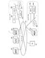
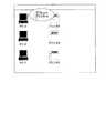
図1は、実施の形態1にかかる表示指示システムのネットワーク構成を示すブロック図である。実施の形態1にかかる表示指示システムは、図1に示すように、機器管理サーバ100a,100bと、表示指示サーバ200と、位置管理サーバ400と、クライアント端末としてのPC700とが、LAN(Local Area Network)やWAN(Wide Area Network)などのネットワーク500を介して接続された構成となっている。(Embodiment 1)
FIG. 1 is a block diagram of a network configuration of the display instruction system according to the first embodiment. As shown in FIG. 1, the display instruction system according to the first embodiment includes an
機器管理サーバ100aは、ネットワークA内のネットワーク機器を管理するサーバであり、機器管理サーバ100bは、ネットワークB内のネットワーク機器を管理するサーバ装置である。 The
図1の例では、ネットワークAのネットワーク機器として、PC−A300a,Printer−A300b,PC−B300c,Printer−B300dが接続されている。また、ネットワークBのネットワーク機器として、PC−C300g,MFP−C300e,Printer−D300fが接続されている。但し、ネットワーク機器としてはこれらのものに限定されるものではない。 In the example of FIG. 1, PC-A 300 a, Printer-A 300 b, PC-
位置管理サーバ400は、ネットワークAおよびネットワークB内の各ネットワーク機器の位置情報を管理するサーバ装置である。ここで、位置情報とは、後述する表示指示サーバ200がクライアント端末であるPC700に送信して表示させる機器レイアウト画面上での各ネットワーク機器の位置座標である。位置管理サーバ400は、各ネットワーク機器の名称等の識別情報と位置情報とを対応付けた位置データベース(図示せず)をハードディスクドライブ装置(HDD)やメモリ等の記憶媒体に格納して保持している。そして、他のサーバ等からネットワーク機器の識別情報を指定した位置情報の要求があった場合には、要求のあったネットワーク機器の位置情報を応答するようになっている。 The
表示指示サーバ200は、配置場所に対応した機器レイアウト画像上の位置に、ネットワーク機器のアイコンを表示した表示画面を、クライアント端末であるPC700に送信して表示させ、PC700からかかる表示画面上での指示を受信して、指示に対応するい処理の実行指示を機器管理サーバ100a,100bに送信するサーバ装置である。 The
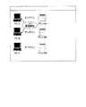
図2は、実施の形態1にかかる表示指示サーバ200の機能的構成を示すブロック図である。表示指示サーバ200は、図2に示すように、位置情報取得部201と、表示画面送信部202と、指示受信部203と、指示送信部204と、処理選択指示部205と、表示方法データベース206(以下「表示方法DB206」)と、機器組合せデータベース207(以下、「機器組合せDB207」という。)と、画面レイアウトやアイコンのデータを保持するHDD208とを主に備えた構成となっている。表示方法DB206と、機器組合せDB207は、HDDやメモリ等の記憶媒体に格納されている。 FIG. 2 is a block diagram of a functional configuration of the
位置情報取得部201は、位置管理サーバ400に対してネットワーク機器の位置情報(画面レイアウト上の位置座標)を要求して取得する処理部である。 The position
表示画面送信部202は、配置場所に対応した画面レイアウト上の位置に、ネットワーク機器のアイコンを表示した表示画面を生成して、PC700に送信して表示させる処理部である。ここで、アイコンは、表示画面上に、各種のデータや処理機能を絵又は絵文字として表示したものをいう。なお、本実施の形態では、表示画面にネットワーク機器のアイコンを表示するように構成しているが、これに限定されるものでなく、アイコンと、各種のデータや処理機能を記号や文字列等によって表示したものとを含むシンボルを表示画面に表示するように構成してもよい。 The display
処理選択指示部205は、PC700で表示された表示画面上で操作者がドラッグアンドドロップ操作による指示を受信した場合に、ドラッグアンドドロップ操作の対象となるアイコンに対応するネットワーク機器の間で実行されるジョブの種類を選択させる処理選択指示をPC700に送信する処理部である。 The process
指示受信部203は、PC700で表示された表示画面上で操作者がドラッグアンドドロップ操作による指示を受信する処理部であり、具体的には、ドラッグアンドドロップ操作の対象となるアイコンに対応するネットワーク機器の機器名と、上記選択指示に応答して指定されたジョブ種類を指示として受信する。 The
指示送信部204は、受信したネットワーク機器の機器名称とジョブ種類とから実行すべき処理を特定して、特定した処理の実行指示を、ドラッグアンドドロップ操作の対象となったネットワーク機器を管理する機器管理サーバに送信する処理部である。 The
表示方法DB206は、ネットワーク機器ごとにネットワーク機器画面レイアウト上での表示方法について定めたデータベースである。図3は、表示方法DB206のデータの内容の一例を示す説明図である。 The display method DB 206 is a database that defines the display method on the network device screen layout for each network device. FIG. 3 is an explanatory diagram illustrating an example of the content of data in the
表示方法DB206は、図3に示すように、ネットワーク機器の機器名と、表示方法と、表示内容と、位置情報とを対応付けて登録している。表示方法としては、ネットワーク機器を画面レイアウト上でどのようなアイコンで表示するかを示すものであり、アイコンの種別とアイコン画像のファイル名が登録されている。表示内容は、ネットワーク機器をアイコンで表示するかマップとして表示するかを指定するものである。位置情報は、位置管理サーバ400から取得したネットワーク機器の画面レイアウト上での位置座標が登録される。 As shown in FIG. 3, the
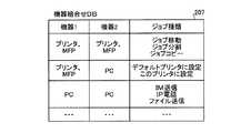
図2に戻り、機器組合せDB207は、ネットワーク機器の組合せにより、アイコンのドラッグアンドドロップ操作で実行可能なジョブ(処理)の種類を登録したデータベースである。図4は、機器組合せDB207のデータの内容の一例を示す説明図である。 Returning to FIG. 2, the
図4に示すように、ドラッグアンドドロップ操作の対象となるネットワーク機器の種類に対応して実行可能なジョブ種類が登録されている。図4において、IM送信とは、インスタントメッセージの送信である。 As shown in FIG. 4, job types that can be executed corresponding to the types of network devices that are targets of the drag-and-drop operation are registered. In FIG. 4, IM transmission is transmission of an instant message.
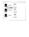
次に、機器管理サーバ100について説明する。図5は、機器管理サーバ100の機能的構成を示すブロック図である。機器管理サーバ100は、図5に示すように、処理実行指示部101と、機器情報送信部102と、機器情報受信部103と、機器情報DB104とを主に備えている。 Next, the device management server 100 will be described. FIG. 5 is a block diagram illustrating a functional configuration of the device management server 100. As illustrated in FIG. 5, the device management server 100 mainly includes a process
機器情報受信部103は、自己が管理するネットワーク内のネットワーク機器のジョブの実行状態等の状態を一定時間ごとにネットワーク機器から受信し、機器情報データベース104(以下、「機器情報DB104」という)に登録する処理部である。 The device
機器情報送信部102は、表示指示サーバ200からネットワーク機器を指定した機器情報要求を受信した場合に、機器情報DB104から該当するネットワーク機器の機器情報を読み出して、読み出した機器情報を表示指示サーバ200に送信する処理部である。 When the device
処理実行指示部101 表示指示サーバ200からの実行指示を受信した場合に、実行指示の対象となるネットワーク機器に対して処理実行の指示を行う処理部である。 Processing
機器情報DB104は、ネットワーク機器に関する機器情報を登録すたデータベースであり、HDDやメモリ等の記憶媒体に格納されている。図6は、機器情報DB104のデータの内容の一例を示す説明図である。 The
機器情報DB104は、図6に示すように、機器情報として、ネットワーク機器の機器名と、機器属性と、IPアドレスと、プレゼンスと、現在ネットワーク機器で実行または実行予定の関連ジョブが登録されている。プレゼンスは、ネットワーク機器の現在の状態を示すものであり、図6に示すように、アイドリング、印刷中などがプレゼンスとして登録されている。 As shown in FIG. 6, in the
次に、以上のように構成された本実施の形態にかかる表示指示システムの全体処理について説明する。図7は、実施の形態1にかかる表示指示システムの全体処理の流れを示すシーケンス図である。 Next, the overall processing of the display instruction system according to the present embodiment configured as described above will be described. FIG. 7 is a sequence diagram of the overall processing flow of the display instruction system according to the first embodiment.
まず、機器管理サーバ100a,100bは、一定時間ごとにネットワーク機器に対して機器情報要求を送信し(ステップS11)、ネットワーク機器はこれに応答して自己の機器情報を返信する(ステップS12)。かかるステップS11、12の処理は、ネットワーク機器ごとにすべて行われ、また一定時間ごとに繰り返し実行される。機器情報を取得した機器管理サーバ100a,100bは、取得した機器情報を機器情報DB104に登録する。 First, the
次に、表示指示サーバ200は、PC700で表示する表示画面を生成するために、機器管理サーバ100に対して、表示画面に表示する全てのネットワーク機器の機器名を指定して機器情報要求を送信する(ステップS13)。機器情報要求を受信した機器管理サーバ100は、機器情報DB104から要求のあったネットワーク機器の機器情報を読み出して、読み出した機器情報を表示指示サーバ200に返信する(ステップS14)。 Next, in order to generate a display screen to be displayed on the
次に、表示指示サーバ200は、位置管理サーバ400に対して、表示画面に表示する全てのネットワーク機器の機器名を指定してネットワーク機器の位置情報要求を送信する(ステップS15)。位置情報要求を受信した位置管理サーバ400は、位置情報DBから要求のあったネットワーク機器の画面レイアウト上の位置座標を読み出して、かかる位置座標を位置情報として表示指示サーバ200に返信する(ステップS16)。ネットワーク機器の位置情報を受信した表示指示サーバ200は、受信した位置情報を表示情報DB206に登録する。 Next, the
そして、表示指示サーバ200は、PC700から表示情報要求を受信すると(ステップ17)、表示および指示処理を実行する(ステップS18)。表示指示サーバ200は、この表示および指示処理の中で、表示画面を生成してPC700に送信する(ステップS19)。 Then, when receiving a display information request from the PC 700 (step 17), the
表示画面を受信したPC700では、表示画面をディスプレイ装置等の表示装置に表示し(ステップS20)、PC700の操作者がかかる表示画面上でネットワーク機器のアイコンをドラッグアンドドロップ操作すると、PC700は、かかる操作を受け付けて(ステップS21)、その旨を表示指示サーバ200に送信する。 In the
表示指示サーバ200は、機器組合せDB207を参照して、ドラッグアンドドロップ操作で指定されたネットワーク機器に対応するジョブ種類を処理選択指示としてPC700に送信する(ステップS22)。 The
PC700は、受信したジョブ種類(処理選択指示)を表示画面上に表示して操作者の処理選択指示を受付け(ステップS23)、指定されたジョブ種類を表示指示サーバ200に送信する(ステップ24)。そして、表示指示サーバ200は、受信したジョブ種類に応じてネットワーク機器で実行する処理を決定し、決定した処理の実行指示を機器管理サーバ100a,100bに送信する(ステップS25)。 The
処理の実行指示を受信した機器管理サーバ100a,100bは、処理実行指示の内容に従って、ネットワーク機器に対して処理の実行を指示する(ステップS26)。これにより、PC700でドラッグアンドドロップ操作の対象となったネットワーク機器間で、指定されたジョブ種類、すなわち処理が実行されることになる。 The
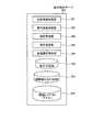
次に、ステップS18の表示および指示処理の詳細について説明する。図8は、表示指示サーバ200で実行される表示および指示処理の手順を示すフローチャートである。PC700から配置場所を指定した表示情報要求を受信すると、表示画面送信部202は、表示方法DB206を参照して、表示方法DB206で設定された内容でネットワーク機器の表示画面を生成する(ステップS31)。この際、HDD208から要求のあった配置場所に対応する画面レイアウトを読み出し、また表示方法DB206で設定されているアイコン画像のファイル名からアイコン画像を読み出す。そして、画面レイアウト上でかかるアイコン画像を表示方法DBの位置情報として登録された座標の位置に配置することにより表示画面を生成する。 Next, details of the display and instruction processing in step S18 will be described. FIG. 8 is a flowchart showing a procedure of display and instruction processing executed by the
次に、表示画面送信部202は、生成した表示画面をPC700に送信する(ステップS32)。PC700ではかかる表示画面を表示し、操作者がこの表示画面上でネットワーク機器のアイコンをドラッグアンドドロップ操作した場合には、表示指示サーバ200の指示受信部203は、ドラッグ元のネットワーク機器の機器名と、ドロップ先のネットワーク機器の機器名とをPC700から受信する(ステップS33)。 Next, the display
そして、処理選択指示部205は、機器組合せDB207を参照して、受信したふたつの機器名に対応するジョブ種類を処理選択指示としてPC700に送信する(ステップS34)。そして、PC700から指定されたジョブ種類を受信し(ステップS35)、受信したジョブ種類に応じて処理実行指示を決定し(ステップS36)、決定した処理実行指示を機器管理サーバ100に送信する(ステップS37)。 Then, the process
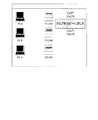
ここで、図9は、プリンタAのアイコンからプリンタBのアイコンにドラッグアンドドロップ操作を行った場合に表示される表示画面の一例を示す模式図である。この場合には、機器組合せDB207から処理選択指示のジョブ種類として、ジョブ移動、ジョブ分割、ジョブコピーが表示される。図10はジョブ分割選択後に表示される表示画面、図11はジョブ移動選択後に表示される表示画面、図12はジョブコピー選択後に表示される表示画面である。 FIG. 9 is a schematic diagram illustrating an example of a display screen displayed when a drag-and-drop operation is performed from the printer A icon to the printer B icon. In this case, job migration, job division, and job copy are displayed as job types for processing selection instructions from the
ここで、ジョブ移動は、ドラッグ元のネットワーク機器で実行されているジョブのドロップ先のネットワーク機器に移動することである。この場合、指示送信部204で決定される機器管理サーバ100への処理実行指示は、ドラッグ元のネットワーク機器で実行されているジョブのキャンセル指示と、当該ジョブのドロップ先のネットワーク機器での生成指示となる。 Here, the job movement is to move to the network device that is the drop destination of the job that is being executed by the dragged network device. In this case, the process execution instruction to the device management server 100 determined by the
また、ジョブ分割は、ドラッグ元のネットワーク機器で実行されている複数のジョブのうち一部のジョブをドロップ先のネットワーク機器に移動することである。この場合、指示送信部204で決定される機器管理サーバ100への処理実行指示は、ドラッグ元のネットワーク機器で実行されているジョブの一部のジョブのキャンセル指示と、当該ジョブのドロップ先のネットワーク機器での生成指示となる。 Also, job division is to move some jobs out of a plurality of jobs being executed on the dragged network device to the drop destination network device. In this case, a process execution instruction to the device management server 100 determined by the
また、ジョブコピーは、ドラッグ元のネットワーク機器で実行されているジョブをドロップ先のネットワーク機器にコピーすることである。この場合、指示送信部204で決定される機器管理サーバ100への処理実行指示は、ドラッグ元のネットワーク機器で実行されているジョブと同一ジョブのドロップ先のネットワーク機器での生成指示となる。 Job copy is copying a job being executed on the dragged network device to the drop destination network device. In this case, the process execution instruction to the device management server 100 determined by the
また、図13は、PC−AからプリンタBのアイコンにドラッグアンドドロップ操作を行った場合に表示される表示画面の一例を示す模式図である。この場合には、機器組合せDB207から処理選択指示のジョブ種類として、デフォルトプリンタに設定、このプリンタに設定が表示される。図14はデフォルトプリンタ設定後に表示される表示画面、図15はこのプリンタに設定後に表示される表示画面である。 FIG. 13 is a schematic diagram illustrating an example of a display screen displayed when a drag-and-drop operation is performed from the PC-A to the printer B icon. In this case, the job combination of the process selection instruction from the
ここで、デフォルトプリンタ設定は、ドラッグ元のネットワーク機器(PC)にデフォルトプリンタとしてドロップ先のネットワーク機器(プリンタ)を設定することである。この場合、指示送信部204で決定される機器管理サーバ100への処理実行指示は、ドラッグ元のネットワーク機器に対するドロップ先のネットワーク機器の設定指示となる。 Here, the default printer setting is to set a drop destination network device (printer) as a default printer in the drag source network device (PC). In this case, the process execution instruction to the device management server 100 determined by the
また、このプリンタに設定は、ドラッグ元のネットワーク機器(PC)の印刷先として一時的に(現在のセッション内、一定時間内など)ドロップ先のネットワーク機器(プリンタ)を設定することである。この場合、指示送信部204で決定される機器管理サーバ100への処理実行指示は、ドラッグ元のネットワーク機器に対するドロップ先のネットワーク機器の一時的な設定指示となる。 The setting for this printer is to temporarily set the drop destination network device (printer) as the print destination of the drag source network device (PC) (in the current session, within a certain period of time, etc.). In this case, the process execution instruction to the device management server 100 determined by the
また、図16は、PC−AからPC−Bのアイコンにドラッグアンドドロップ操作を行った場合に表示される表示画面の一例を示す模式図である。この場合には、機器組合せDB207から処理選択指示のジョブ種類として、IM送信、IP電話、ファイル送信が表示される。図17はIM送信設定後に表示される表示画面、図18はIP電話設定後に表示される表示画面、図19はファイル送信後に表示される表示画面である。 FIG. 16 is a schematic diagram illustrating an example of a display screen displayed when a drag-and-drop operation is performed from the PC-A to the PC-B icon. In this case, IM transmission, IP phone, and file transmission are displayed as job types for processing selection instructions from the
ここで、IM送信は、ドラッグ元のネットワーク機器(PC)とドロップ先のネットワーク機器(PC)との間でインスタントメッセージのプログラムを起動して、互いに相手先のネットワーク機器のIPアドレスを宛先として指定することである。この場合、指示送信部204で決定される機器管理サーバ100への処理実行指示は、ドラッグ元およびドロップ先のネットワーク機器でのインスタントメッセージプログラムの起動指示、宛先としての相手先のIPアドレスの指定指示となる。 Here, in IM transmission, an instant message program is started between the drag-source network device (PC) and the drop-destination network device (PC), and the destination network device IP address is specified as the destination. It is to be. In this case, the process execution instruction to the device management server 100 determined by the
ここで、IP電話は、ドラッグ元のネットワーク機器(PC)とドロップ先のネットワーク機器(PC)との間でIP電話のプログラムを起動して、互いに相手先のネットワーク機器のIPアドレスを宛先として指定することである。この場合、指示送信部204で決定される機器管理サーバ100への処理実行指示は、ドラッグ元およびドロップ先のネットワーク機器でのIP電話のプログラムの起動指示、宛先としての相手先のIPアドレスの指定指示となる。 Here, the IP phone starts the IP phone program between the drag-source network device (PC) and the drop-destination network device (PC), and designates the IP address of the partner network device as the destination. It is to be. In this case, the process execution instruction to the device management server 100 determined by the
ここで、ファイル送信は、ドラッグ元のネットワーク機器(PC)からドロップ先のネットワーク機器(PC)へのファイル転送を行うことである。この場合、指示送信部204で決定される機器管理サーバ100への処理実行指示は、ドラッグ元からドロップ先のネットワーク機器へのファイル転送指示となる。 Here, the file transmission is a file transfer from the drag-source network device (PC) to the drop-destination network device (PC). In this case, the process execution instruction to the device management server 100 determined by the
このように実施の形態1にかかる表示指示システムでは、表示指示サーバ200がネットワーク機器のアイコンを画面レイアウト上に配置した表示画面をPC700に送信して表示させ、PC700上で操作者による複数のネットワーク機器のアイコン間でドラッグアントドロップ操作が行われた場合に、ドラッグアントドロップ操作の対象となるネットワーク機器の間でジョブに関する処理、通信に関する処理を実行させる実行指示を、前記ドラッグアントドロップ操作の対象となるネットワーク機器を管理する機器管理サーバ100に送信してネットワーク機器間で実行しているので、ネットワーク機器の負荷分散を図るとともに、ネットワーク機器やネットワーク機器を利用した処理を操作者に容易に把握することができる。 As described above, in the display instruction system according to the first embodiment, the
(実施の形態2)
実施の形態2にかかる表示指示システムでは、さらに利用者のアイコンを表示画面上に表示させて、当該利用者のアイコンもドラッグアンドドロップ操作の対象として、利用者が使用するネットワーク機器間で種々の処理を実行させるものである。(Embodiment 2)
In the display instruction system according to the second embodiment, a user icon is further displayed on the display screen, and the user icon is also subjected to a drag-and-drop operation. The process is executed.
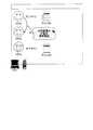
図20は、実施の形態2にかかる表示指示システムのネットワーク構成を示すブロック図である。実施の形態2にかかる表示指示システムは、図20に示すように、機器管理サーバ100a,100bと、表示指示サーバ2200と、プレゼンス管理サーバ2600と、位置管理サーバ400と、クライアント端末としてのPC700とが、LAN(Local Area Network)やWAN(Wide Area Network)などのネットワーク500を介して接続された構成となっている。機器管理サーバ100a、位置管理サーバ400、PC700、ネットワークA、BN内のネットワーク機器については実施の形態1と同様である。 FIG. 20 is a block diagram of a network configuration of the display instruction system according to the second embodiment. As shown in FIG. 20, the display instruction system according to the second embodiment includes
プレゼンス管理サーバ2600は、利用者ごとに可能なジョブ種類を示すプレゼンスを管理するサーバ装置である。プレゼンス管理サーバ2600の詳細については後述する。 The
本実施の形態にかかる表示指示サーバ2200は、実施の形態1と同様の機能の他、さらに、画面レイアウト上にネットワーク機器を使用する利用者のアイコンを表示した表示画面をPC700に送信し、PC700から、操作者による複数の利用者のアイコン間のドラッグアントドロップ操作を受け付けた場合に、ドラッグアントドロップ操作の対象となる複数の利用者が使用するネットワーク機器の間で所定の処理を実行させる実行指示を、ドラッグアントドロップ操作の対象となる利用者が使用するネットワーク機器に送信する機能を有している。 The
図21は、実施の形態2にかかる表示指示サーバ2200の機能的構成を示すブロック図である。表示指示サーバ2200は、図21に示すように、位置情報取得部201と、表示画面送信部2202と、指示受信部203と、指示送信部204と、処理選択指示部205と、表示方法DB206と、機器組合せDB207と、プレゼンス組合せデータベース2207(以下、「プレゼンス組合せDB2207」という。)と、画面レイアウトやアイコンのデータを保持するHDD208とを主に備えた構成となっている。表示方法DB206と、機器組合せDB207と、プレゼンス組合せDB2207は、HDDやメモリ等の記憶媒体に格納されている。 FIG. 21 is a block diagram of a functional configuration of the
ここで、位置情報取得部201、指示受信部203、指示送信部204と、表示方法DB206、機器組合せDB207、HDD208は実施の形態1と同様である。 Here, the position
表示画面送信部2202は、実施の形態1と同様に、配置場所に対応した画面レイアウト上の位置に、ネットワーク機器のアイコンを表示する他、利用者のアイコンを表示した表示画面を生成して、PC700に送信して表示させる処理部である。また、表示画面送信部2202は、プレゼンス管理サーバ2600に対して利用者の氏名を指定したプレゼンス要求を行い、プレゼンス管理サーバ2600から利用者のプレゼンスを取得する処理も行う。ここで、プレゼンスとは、利用者が使用可能なジョブの処理種類、すなわちジョブ種類である。 Similar to the first embodiment, the display
プレゼンス組合せDB2207は、2人の利用者のプレゼンスに対応したジョブ種類を登録したデータベースである。 The
図22は、プレゼンス組合せDB2207のデータの内容の一例を示す説明図である。図22に示すように、プレゼンス組合せDB2207には、2人の利用者のプレゼンスに重複するプレゼンスをジョブ種類として登録している。 FIG. 22 is an explanatory diagram showing an example of the contents of data in the
次に、プレゼンス管理サーバ2600について説明する。図23は、プレゼンス管理サーバ2600の機能的構成を示すブロック図である。プレゼンス管理サーバ2600は、図23に示すように、プレゼンス送信部2601と、プレゼンス受信部2602と、プレゼンスデータベース2603(以下、「プレゼンスDB2603」という。)とを主に備えている。 Next, the
プレゼンス受信部2602は、利用者が使用するネットワーク機器からプレゼンスを受信してプレゼンスDB2603に登録する処理部である。 The
プレゼンス送信部2601は、表示指示サーバ2200から利用者のプレゼンス要求を受信した場合、プレゼンスDB2603から要求された利用者のプレゼンスを読み出して、読み出したプレゼンスを表示指示サーバ2200に送信する処理部である。 The
プレゼンスDB2603は、利用者のプレゼンスを登録したデータベースであり、HDDやメモリ等の記憶媒体に格納されている。図24は、プレゼンスDBのデータの内容の一例を示す説明図である。 The
プレゼンスDB2603は、図24に示すように、利用者の氏名と、利用者が使用するネットワーク機器(PC,端末)の機器名と、当該ネットワーク機器のIPアドレスと、プレゼンスとが登録されている。 As shown in FIG. 24, the
次に、以上のように構成された本実施の形態にかかる表示指示システムの全体処理について説明する。図25は、実施の形態2にかかる表示指示システムの全体処理の流れを示すシーケンス図である。 Next, the overall processing of the display instruction system according to the present embodiment configured as described above will be described. FIG. 25 is a sequence diagram illustrating an overall process flow of the display instruction system according to the second embodiment.
ステップS41からS47までの処理は、実施の形態1におけるステップS1からS17までの処理と同様に行われる。表示指示サーバ2200がPC700から表示情報要求を受信すると、表示および指示処理が実行される(ステップS48)。この実施の形態2
では、この表示および指示処理の中で、表示画面に利用者のアイコンを表示するため、利用者のプレゼンスをプレゼンス管理サーバ2600に対して要求し(ステップS49)、その応答として利用者のプレゼンスを取得する(ステップS50)。そして、利用者のアイコンを含めて表示画面を生成してPC700に送信し(ステップS51)、PC700では受信した表示画面を表示する(ステップS52)。図26は、実施の形態2にかかる表示画面の一例を示す模式図である。図26に示すように、表示画面には、利用者のアイコンが表示され、さらに利用者が使用可能なネットワーク機器のアイコンも一覧表示されている。The processing from step S41 to S47 is performed in the same manner as the processing from step S1 to S17 in the first embodiment. When the
In this display and instruction process, in order to display the user icon on the display screen, the
これ以降のステップS53からS58までの処理は、実施の形態1におけるステップS21からS26までの処理と同様に行われる。ただし、本実施の形態では、表示画面上で利用者のアイコンに対してドラッグアンドドロップ操作が可能であり、かかる操作が行われた場合の処理については、表示および指示処理の詳細において説明する。 The subsequent processing from step S53 to S58 is performed in the same manner as the processing from step S21 to S26 in the first embodiment. However, in the present embodiment, a drag-and-drop operation can be performed on the user's icon on the display screen, and the processing when such an operation is performed will be described in detail in the display and instruction processing.
次に、ステップS48の表示および指示処理の詳細について説明する。図27は、実施の形態2における表示指示サーバ200で実行される表示および指示処理の手順を示すフローチャートである。 Next, details of the display and instruction processing in step S48 will be described. FIG. 27 is a flowchart illustrating a procedure of display and instruction processing executed by the
PC700から配置場所を指定した表示情報要求を受信すると、表示画面送信部2202は、プレゼンス管理サーバ2600に対して表示画面に表示すべき利用者のプレゼンスの要求を送信する(ステップS61)。 When receiving the display information request specifying the location from the
そして、プレゼンス管理サーバ2600から利用者のプレゼンスを受信すると(ステップS62)、受信したプレゼンスの中から2つずつ選択し、選択した2つずつの利用者のプレゼンスから重複するプレゼンスを選択する(ステップS63)。 When the presence of the user is received from the presence management server 2600 (step S62), two of the received presences are selected, and an overlapping presence is selected from the two selected user presences (step S62). S63).
そして、表示画面送信部2202は、選択した重複するプレゼンスをジョブ種類として、2つの利用者のプレゼンスと対応付けて、プレゼンス組合せDB2207に登録する(ステップS64)。 Then, the display
次いで、表示画面送信部2202は、利用者のプレゼンスと表示方法DB206で設定された内容でネットワーク機器および利用者の表示画面を生成する(ステップS65)。この際、HDD208から要求のあった配置場所に対応する画面レイアウトを読み出し、また表示方法DB206で設定されているアイコン画像のファイル名からアイコン画像を読み出す。そして、画面レイアウト上でかかるアイコン画像を表示方法DBの位置情報として登録された座標の位置に配置することにより表示画面を生成する。 Next, the display
次に、表示画面送信部2202は、生成した表示画面をPC700に送信する(ステップS66)。PC700ではかかる表示画面を表示し、操作者がこの表示画面上でネットワーク機器のアイコンまたは利用者のアイコンをドラッグアンドドロップ操作した場合には、表示指示サーバ200の指示受信部203は、ドラッグアンドドロップ操作の対象のアイコンを種類を調べる(ステップS67)。 Next, the display
そして、ドラッグアンドドロップ操作の対象のアイコンがネットワーク機器のアイコンである場合には、処理選択指示部205は、機器組合せDB207を参照して、受信したふたつの機器名に対応するジョブ種類を処理選択指示としてPC700に送信する(ステップS68)。 If the target icon for the drag-and-drop operation is an icon for a network device, the processing
一方、ステップS67において、ドラッグアンドドロップ操作の対象のアイコンが利用者のアイコンである場合には、プレゼンス組合せDB2207を参照して、受信した2つの利用者のプレゼンスに対応するジョブ種類を処理選択指示としてPC700に送信する(ステップS69)。 On the other hand, if the icon to be dragged and dropped in step S67 is the user icon, the
そして、PC700から指定されたジョブ種類を受信し(ステップS70)、受信したジョブ種類に応じて処理実行指示を決定し(ステップS71)、決定した処理実行指示を機器管理サーバ100に送信する(ステップS72)。 Then, the designated job type is received from the PC 700 (step S70), a process execution instruction is determined according to the received job type (step S71), and the determined process execution instruction is transmitted to the device management server 100 (step S71). S72).
ここで、図28は、AさんのアイコンからBさんのアイコンにドラッグアンドドロップ操作を行った場合に表示される表示画面の一例を示す模式図である。この場合には、プレゼンス組合せDB2207から処理選択指示のジョブ種類として、IM送信、IP電話、携帯電話が表示される。図29はIM送信設定後に表示される表示画面、図30はIP電話設定後に表示される表示画面、図31はファイル送信後に表示される表示画面である。 Here, FIG. 28 is a schematic diagram illustrating an example of a display screen displayed when a drag-and-drop operation is performed from the icon of Mr. A to the icon of Mr. B. In this case, IM transmission, IP phone, and mobile phone are displayed from the
ここで、IM送信は、ドラッグ元の利用者に対応する(使用する)ネットワーク機器とドロップ先の利用者に対応するネットワーク機器との間でインスタントメッセージのプログラムを起動して、互いに相手先の利用者に対応するネットワーク機器のIPアドレスを宛先として指定することである。この場合、指示送信部204で決定される機器管理サーバ100への処理実行指示は、ドラッグ元およびドロップ先の利用者に対応するネットワーク機器でのインスタントメッセージプログラムの起動指示、宛先としての相手先の利用者のIPアドレスの指定指示となる。 Here, in IM transmission, an instant message program is started between the network device corresponding to (using) the drag-source user and the network device corresponding to the drop-destination user, and the other party's use of each other The IP address of the network device corresponding to the user is designated as the destination. In this case, the process execution instruction to the device management server 100 determined by the
また、IP電話は、ドラッグ元の利用者に対応するネットワーク機器とドロップ先の利用者に対応するネットワーク機器との間でIP電話のプログラムを起動して、互いに相手先の利用者に対応するネットワーク機器のIPアドレスを宛先として指定することである。この場合、指示送信部204で決定される機器管理サーバ100への処理実行指示は、ドラッグ元およびドロップ先の利用者に対応するネットワーク機器でのIP電話のプログラムの起動指示、宛先としての相手先の利用者のIPアドレスの指定指示となる。 In addition, the IP phone starts the IP phone program between the network device corresponding to the drag-source user and the network device corresponding to the drop-destination user, and mutually corresponds to the other-party user. This is to specify the IP address of the device as the destination. In this case, the process execution instruction to the device management server 100 determined by the
また、携帯電話は、ドラッグ元の利用者に対応するネットワーク機器とドロップ先の利用者に対応するネットワーク機器との間で携帯電話の通信開始を行うことである。この場合、指示送信部204で決定される機器管理サーバ100への処理実行指示は、ドラッグ元からドロップ先の利用者に対応する携帯電話の電話番号を指定した通話の開始指示となる。 Also, the mobile phone is to start communication of the mobile phone between the network device corresponding to the drag-source user and the network device corresponding to the drop-destination user. In this case, the process execution instruction to the device management server 100 determined by the
このように実施の形態2にかかる表示指示システムでは、表示指示サーバ2200がネットワーク機器のアイコンの他、利用者のアイコンを画面レイアウト上に配置した表示画面をPC700に送信して表示させ、PC700上で操作者による複数の利用者のアイコン間でドラッグアントドロップ操作が行われた場合に、ドラッグアントドロップ操作の対象となる利用者が使用するネットワーク機器の間で通信に関する処理を実行させる実行指示を、前記ドラッグアントドロップ操作の対象となる利用者が使用するネットワーク機器を管理する機器管理サーバ100に送信してネットワーク機器間で実行しているので、ネットワーク機器の負荷分散を図るとともに、ネットワーク機器やネットワーク機器を利用した処理を操作者により一層容易に把握することができる。 As described above, in the display instruction system according to the second embodiment, the
実施の形態1および2の表示指示サーバ200、2200、位置管理サーバ400、機器管理サーバ100a,100b、プレゼンス管理サーバ2600は、CPUなどの制御装置と、ROM(Read Only Memory)やRAMなどの記憶装置と、HDD、CDドライブ装置などの外部記憶装置と、ディスプレイ装置などの表示装置と、キーボードやマウスなどの入力装置を備えており、通常のコンピュータを利用したハードウェア構成となっている。 The
実施の形態1および2の表示指示サーバ200で実行される表示指示プログラムは、インストール可能な形式又は実行可能な形式のファイルでCD−ROM、フレキシブルディスク(FD)、CD−R、DVD(Digital Versatile Disk)等のコンピュータで読み取り可能な記録媒体に記録されて提供される。 The display instruction program executed by the
また、実施の形態1および2の表示指示サーバ200で実行される表示指示プログラムを、インターネット等のネットワークに接続されたコンピュータ上に格納し、ネットワーク経由でダウンロードさせることにより提供するように構成しても良い。また、実施の形態1および2の表示指示サーバ200で実行される表示指示プログラムをインターネット等のネットワーク経由で提供または配布するように構成しても良い。 Further, the display instruction program executed by the
また、実施の形態1および2の表示指示サーバ200で実行される表示指示プログラムを、ROM等に予め組み込んで提供するように構成してもよい。 Further, the display instruction program executed by the
実施の形態1および2の表示指示サーバ200で実行される表示指示プログラムは、上述した各部(位置情報取得部201、表示画面送信部202,2202、指示受信部203、指示送信部204、処理選択指示部205)を含むモジュール構成となっており、実際のハードウェアとしてはCPU(プロセッサ)が上記記憶媒体から表示指示プログラムを読み出して実行することにより上記各部が主記憶装置上にロードされ、位置情報取得部201、表示画面送信部202,2202、指示受信部203、指示送信部204、処理選択指示部205が主記憶装置上に生成されるようになっている。 The display instruction program executed by the
なお、本発明は、上記実施の形態そのままに限定されるものではなく、実施段階ではその要旨を逸脱しない範囲で構成要素を変形して具体化することができる。また、上記実施の形態に開示されている複数の構成要素の適宜な組み合わせにより、種々の発明を形成することができる。例えば、実施の形態に示される全構成要素からいくつかの構成要素を削除してもよい。さらに、異なる実施の形態にわたる構成要素を適宜組み合わせても良い。 It should be noted that the present invention is not limited to the above-described embodiment as it is, and can be embodied by modifying the constituent elements without departing from the scope of the invention in the implementation stage. In addition, various inventions can be formed by appropriately combining a plurality of constituent elements disclosed in the above embodiments. For example, some components may be deleted from all the components shown in the embodiment. Furthermore, constituent elements over different embodiments may be appropriately combined.
100a,100b 機器管理サーバ
101 処理実行指示部
103 機器情報受信部
201 位置情報取得部
202,2202 表示画面送信部
204 指示送信部
206 表示方法データベース
207 機器組合せデータベース
400 位置管理サーバ
2200 表示指示サーバ
2202 表示画面送信部
2600 プレゼンス管理サーバ
2601 プレゼンス送信部
2602 プレゼンス受信部100a, 100b
Claims (12)
Translated fromJapanese前記クライアント端末から、操作者による複数のネットワーク機器のシンボル間でドラッグアンドドロップ操作を受け付けた場合に、ドラッグアンドドロップ操作の対象となる前記複数のネットワーク機器の間で所定の処理を実行させる実行指示を、前記ドラッグアンドドロップ操作の対象となる前記複数のネットワーク機器に送信する指示送信手段と、を備え、
前記ドラッグアンドドロップ操作の対象となる前記複数のネットワーク機器のシンボルは、いずれも画像形成装置のシンボルであり、
前記指示送信手段は、前記画像形成装置で実行されるジョブに関する処理を前記所定の処理として実行させる実行指示を、前記ドラッグアンドドロップ操作の対象となる前記複数の画像形成装置に送信することを特徴とする表示指示装置。Display screen transmitting means for transmitting a display screen displaying symbols of a plurality of network devices connected to the network to a client terminal connected to the network at a position on the map image corresponding to the arrangement location;
Execution instruction to execute a predetermined process between the plurality of network devices that are targets of the drag-and- drop operation when an operator accepts a drag-and- drop operation between the symbols of the plurality of network devices from the client terminal An instruction transmission means for transmitting to the plurality of network devices subject to the drag-and- drop operation,
The symbols of the plurality of network devices that are targets of the drag and drop operation are all symbols of the image forming apparatus,
The instruction transmission unit transmits an execution instruction for executing a process related to a job executed in the image forming apparatus as the predetermined process to the plurality of image forming apparatuses that are targets of the drag and drop operation. Display instruction device.
前記指示送信手段は、前記クライアント端末から、前記操作者による選択指示が行われた前記ジョブに関する処理を実行させる前記実行指示を、前記ドラッグアンドドロップ操作の対象となる前記複数の画像形成装置に送信することを特徴とする請求項1に記載の表示指示装置。When the operator accepts a drag-and- drop operation between a plurality of symbols of the image forming apparatus by an operator, an instruction to select one of job move, job split, or job copy as the process related to the job Processing selection instruction means for performing the processing on the client terminal,
The instruction transmission unit transmits, from the client terminal, the execution instruction for executing processing related to the job for which the selection instruction has been given by the operator to the plurality of image forming apparatuses that are targets of the drag-and- drop operation. The display instruction apparatus according to claim1 , wherein the display instruction apparatus is a display instruction apparatus.
前記クライアント端末から、操作者による複数のネットワーク機器のシンボル間でドラッグアンドドロップ操作を受け付けた場合に、ドラッグアンドドロップ操作の対象となる前記複数のネットワーク機器の間で所定の処理を実行させる実行指示を、前記ドラッグアンドドロップ操作の対象となる前記複数のネットワーク機器に送信する指示送信手段と、を備え、
前記ドラッグアンドドロップ操作の対象となる前記複数のネットワーク機器のシンボルは、いずれも情報処理装置のシンボルであり、
前記指示送信手段は、前記複数の情報処理装置の間で行われる通信処理を前記所定の処理として実行させる実行指示を、前記ドラッグアンドドロップ操作の対象となる前記複数の情報処理装置に送信することを特徴とする表示指示装置。Display screen transmitting means for transmitting a display screen displaying symbols of a plurality of network devices connected to the network to a client terminal connected to the network at a position on the map image corresponding to the arrangement location;
Execution instruction to execute a predetermined process between the plurality of network devices that are targets of the drag-and-drop operation when an operator accepts a drag-and-drop operation between the symbols of the plurality of network devices from the client terminal An instruction transmission means for transmitting to the plurality of network devices subject to the drag-and-drop operation,
The symbols of the plurality of network devices that are targets of the drag-and-drop operation are all information processing device symbols,
The instruction transmitting means transmits an execution instruction for executing communication processing performed between the plurality of information processing apparatuses as the predetermined process to the plurality of information processing apparatuses that are targets of the drag-and- drop operation.Viewing indicating device characterized.
前記指示送信手段は、前記クライアント端末から、前記操作者による選択指示が行われた前記通信に関する処理を実行させる前記実行指示を、前記ドラッグアンドドロップ操作の対象となる前記複数の情報処理装置に送信することを特徴とする請求項3に記載の表示指示装置。When the operator receives a drag-and- drop operation between the symbols of the plurality of information processing apparatuses by the operator, the process related to the communication is selected as a message transmission or an IP telephone or file transmission process. Processing selection instruction means for performing the processing on the client terminal,
The instruction transmission means transmits the execution instruction for executing the processing related to the communication in which the selection instruction by the operator is performed from the client terminal to the plurality of information processing apparatuses that are targets of the dragand drop operation. The display instruction device according to claim3 , wherein the display instruction device is a display instruction device.
前記クライアント端末から、操作者による複数のネットワーク機器のシンボル間でドラッグアンドドロップ操作を受け付けた場合に、ドラッグアンドドロップ操作の対象となる前記複数のネットワーク機器の間で所定の処理を実行させる実行指示を、前記ドラッグアンドドロップ操作の対象となる前記複数のネットワーク機器に送信する指示送信手段と、を備え、
前記表示画面送信手段は、さらに、前記地図画像上に前記ネットワーク機器を使用する利用者のシンボルを表示した前記表示画面を、前記クライアント端末に送信し、
前記指示送信手段は、さらに、前記クライアント端末から、操作者による前記複数の利用者のシンボル間のドラッグアンドドロップ操作を受け付けた場合に、ドラッグアンドドロップ操作の対象となる前記複数の利用者が使用する前記複数のネットワーク機器の間で所定の処理を実行させる実行指示を、前記ドラッグアンドドロップ操作の対象となる前記複数の利用者が使用するネットワーク機器に送信することを特徴とする表示指示装置。Display screen transmitting means for transmitting a display screen displaying symbols of a plurality of network devices connected to the network to a client terminal connected to the network at a position on the map image corresponding to the arrangement location;
Execution instruction to execute a predetermined process between the plurality of network devices that are targets of the drag-and-drop operation when an operator accepts a drag-and-drop operation between the symbols of the plurality of network devices from the client terminal An instruction transmission means for transmitting to the plurality of network devices subject to the drag-and-drop operation,
The display screen transmission means further transmits the display screen displaying a symbol of a user who uses the network device on the map image to the client terminal,
The instruction transmission unit is further used by the plurality of users who are targets of the drag-and- drop operation when accepting a drag-and- drop operation between the symbols of the plurality of users by the operator from the client terminal. wherein the plurality of the execution instruction to execute a predetermined process between the network equipment, thedrag-and-drop operationViewing instructions subject to said plurality of usersyou and transmits to the network equipment used in the apparatus.
前記指示送信手段は、前記クライアント端末から、前記操作者による選択指示が行われた前記通信に関する処理を実行させる前記実行指示を、前記ドラッグアンドドロップ操作の対象となる前記利用者が使用する複数の情報処理装置に送信することを特徴とする請求項6に記載の表示指示装置。When a drag-and- drop operation is accepted between the symbols of a plurality of users by an operator from the client terminal, a message transmission or an instruction to select either one of IP telephone or file transmission is given as the processing related to the communication. Processing selection instruction means for the client terminal,
The instruction transmission means uses a plurality of execution instructions used by the user who is a target of the drag-and- drop operation, to execute the processing related to the communication for which the selection instruction by the operator is performed from the client terminal. The display instruction apparatus according to claim6 , wherein the display instruction apparatus transmits the information to the information processing apparatus.
前記クライアント端末から、操作者による複数のネットワーク機器のシンボル間でドラッグアンドドロップ操作を受け付けた場合に、ドラッグアンドドロップ操作の対象となる前記複数のネットワーク機器の間で所定の処理を実行させる実行指示を、前記ドラッグアンドドロップ操作の対象となる前記複数のネットワーク機器に送信する指示送信手段と、を備え、
前記指示送信手段は、 ネットワークに接続され、前記ネットワーク機器に対して前記所定の処理の実行を指示する機器管理装置に対して前記実行指示を送信することを特徴とする表示指示装置。Display screen transmitting means for transmitting a display screen displaying symbols of a plurality of network devices connected to the network to a client terminal connected to the network at a position on the map image corresponding to the arrangement location;
Execution instruction to execute a predetermined process between the plurality of network devices that are targets of the drag-and-drop operation when an operator accepts a drag-and-drop operation between the symbols of the plurality of network devices from the client terminal An instruction transmission means for transmitting to the plurality of network devices subject to the drag-and-drop operation,
The instruction transmitting unit is connected to the network,the display instructing device and transmits the execution instruction to the device management apparatus instructs execution of the predetermined processing for the network device.
配置場所に対応した地図画像上の位置に、ネットワークに接続された複数のネットワーク機器のシンボルを表示した表示画面を、ネットワークに接続されたクライアント端末に送信する表示画面送信ステップと、 A display screen transmission step of transmitting a display screen displaying symbols of a plurality of network devices connected to the network to a client terminal connected to the network at a position on the map image corresponding to the arrangement location;
前記クライアント端末から、操作者による複数のネットワーク機器のシンボル間でドラッグアンドドロップ操作を受け付けた場合に、ドラッグアンドドロップ操作の対象となる前記複数のネットワーク機器の間で所定の処理を実行させる実行指示を、前記ドラッグアンドドロップ操作の対象となる前記複数のネットワーク機器に送信する指示送信ステップと、を前記コンピュータに実行させ、 Execution instruction to execute a predetermined process between the plurality of network devices that are targets of the drag-and-drop operation when an operator accepts a drag-and-drop operation between the symbols of the plurality of network devices from the client terminal Transmitting the instruction to the plurality of network devices to be the target of the drag-and-drop operation, and causing the computer to execute
前記ドラッグアンドドロップ操作の対象となる前記複数のネットワーク機器のシンボルは、いずれも画像形成装置のシンボルであり、 The symbols of the plurality of network devices that are targets of the drag and drop operation are all symbols of the image forming apparatus,
前記指示送信ステップは、前記画像形成装置で実行されるジョブに関する処理を前記所定の処理として実行させる実行指示を、前記ドラッグアンドドロップ操作の対象となる前記複数の画像形成装置に送信することを特徴とするプログラム。 The instruction transmission step transmits an execution instruction to execute a process related to a job executed in the image forming apparatus as the predetermined process to the plurality of image forming apparatuses that are targets of the drag and drop operation. Program.
配置場所に対応した地図画像上の位置に、ネットワークに接続された複数のネットワーク機器のシンボルを表示した表示画面を、ネットワークに接続されたクライアント端末に送信する表示画面送信ステップと、 A display screen transmission step of transmitting a display screen displaying symbols of a plurality of network devices connected to the network to a client terminal connected to the network at a position on the map image corresponding to the arrangement location;
前記クライアント端末から、操作者による複数のネットワーク機器のシンボル間でドラッグアンドドロップ操作を受け付けた場合に、ドラッグアンドドロップ操作の対象となる前記複数のネットワーク機器の間で所定の処理を実行させる実行指示を、前記ドラッグアンドドロップ操作の対象となる前記複数のネットワーク機器に送信する指示送信ステップと、前記コンピュータに実行させ、 Execution instruction to execute a predetermined process between the plurality of network devices that are targets of the drag-and-drop operation when an operator accepts a drag-and-drop operation between the symbols of the plurality of network devices from the client terminal Is transmitted to the plurality of network devices that are targets of the drag-and-drop operation, and is executed by the computer,
前記ドラッグアンドドロップ操作の対象となる前記複数のネットワーク機器のシンボルは、いずれも情報処理装置のシンボルであり、 The symbols of the plurality of network devices that are targets of the drag-and-drop operation are all information processing device symbols,
前記指示送信ステップは、前記複数の情報処理装置の間で行われる通信処理を前記所定の処理として実行させる実行指示を、前記ドラッグアンドドロップ操作の対象となる前記複数の情報処理装置に送信することを特徴とするプログラム。 The instruction transmission step transmits an execution instruction for executing a communication process performed between the plurality of information processing apparatuses as the predetermined process to the plurality of information processing apparatuses that are targets of the drag-and-drop operation. A program characterized by
配置場所に対応した地図画像上の位置に、ネットワークに接続された複数のネットワーク機器のシンボルを表示した表示画面を、ネットワークに接続されたクライアント端末に送信する表示画面送信ステップと、 A display screen transmission step of transmitting a display screen displaying symbols of a plurality of network devices connected to the network to a client terminal connected to the network at a position on the map image corresponding to the arrangement location;
前記クライアント端末から、操作者による複数のネットワーク機器のシンボル間でドラッグアンドドロップ操作を受け付けた場合に、ドラッグアンドドロップ操作の対象となる前記複数のネットワーク機器の間で所定の処理を実行させる実行指示を、前記ドラッグアンドドロップ操作の対象となる前記複数のネットワーク機器に送信する指示送信ステップと、を前記コンピュータに実行させ、 Execution instruction to execute a predetermined process between the plurality of network devices that are targets of the drag-and-drop operation when an operator accepts a drag-and-drop operation between the symbols of the plurality of network devices from the client terminal Transmitting the instruction to the plurality of network devices to be the target of the drag-and-drop operation, and causing the computer to execute
前記表示画面送信ステップは、さらに、前記地図画像上に前記ネットワーク機器を使用する利用者のシンボルを表示した前記表示画面を、前記クライアント端末に送信し、 The display screen transmission step further transmits the display screen displaying a symbol of a user who uses the network device on the map image to the client terminal,
前記指示送信ステップは、さらに、前記クライアント端末から、操作者による前記複数の利用者のシンボル間のドラッグアンドドロップ操作を受け付けた場合に、ドラッグアンドドロップ操作の対象となる前記複数の利用者が使用する前記複数のネットワーク機器の間で所定の処理を実行させる実行指示を、前記ドラッグアンドドロップ操作の対象となる前記複数の利用者が使用するネットワーク機器に送信することを特徴とするプログラム。 The instruction transmission step is further used by the plurality of users who are targets of the drag-and-drop operation when accepting a drag-and-drop operation between the symbols of the plurality of users by the operator from the client terminal. An execution instruction for executing a predetermined process between the plurality of network devices is transmitted to the network device used by the plurality of users to be subjected to the drag-and-drop operation.
配置場所に対応した地図画像上の位置に、ネットワークに接続された複数のネットワーク機器のシンボルを表示した表示画面を、ネットワークに接続されたクライアント端末に送信する表示画面送信ステップと、 A display screen transmission step of transmitting a display screen displaying symbols of a plurality of network devices connected to the network to a client terminal connected to the network at a position on the map image corresponding to the arrangement location;
前記クライアント端末から、操作者による複数のネットワーク機器のシンボル間でドラッグアンドドロップ操作を受け付けた場合に、ドラッグアンドドロップ操作の対象となる前記複数のネットワーク機器の間で所定の処理を実行させる実行指示を、前記ドラッグアンドドロップ操作の対象となる前記複数のネットワーク機器に送信する指示送信ステップと、を前記コンピュータに実行させ、 Execution instruction to execute a predetermined process between the plurality of network devices that are targets of the drag-and-drop operation when an operator accepts a drag-and-drop operation between the symbols of the plurality of network devices from the client terminal Transmitting the instruction to the plurality of network devices to be the target of the drag-and-drop operation, and causing the computer to execute
前記指示送信ステップは、 ネットワークに接続され、前記ネットワーク機器に対して前記所定の処理の実行を指示する機器管理装置に対して前記実行指示を送信することを特徴とするプログラム。 The instruction transmitting step transmits the execution instruction to a device management apparatus connected to a network and instructing the network device to execute the predetermined process.
Priority Applications (2)
| Application Number | Priority Date | Filing Date | Title |
|---|---|---|---|
| JP2007064113AJP4866272B2 (en) | 2007-03-13 | 2007-03-13 | Display instruction apparatus and program |
| US12/046,905US8443289B2 (en) | 2007-03-13 | 2008-03-12 | Display instruction apparatus, display instruction method, and computer program product |
Applications Claiming Priority (1)
| Application Number | Priority Date | Filing Date | Title |
|---|---|---|---|
| JP2007064113AJP4866272B2 (en) | 2007-03-13 | 2007-03-13 | Display instruction apparatus and program |
Publications (2)
| Publication Number | Publication Date |
|---|---|
| JP2008225918A JP2008225918A (en) | 2008-09-25 |
| JP4866272B2true JP4866272B2 (en) | 2012-02-01 |
Family
ID=39763923
Family Applications (1)
| Application Number | Title | Priority Date | Filing Date |
|---|---|---|---|
| JP2007064113AExpired - Fee RelatedJP4866272B2 (en) | 2007-03-13 | 2007-03-13 | Display instruction apparatus and program |
Country Status (2)
| Country | Link |
|---|---|
| US (1) | US8443289B2 (en) |
| JP (1) | JP4866272B2 (en) |
Families Citing this family (15)
| Publication number | Priority date | Publication date | Assignee | Title |
|---|---|---|---|---|
| US8082514B2 (en)* | 2007-09-13 | 2011-12-20 | Dell Products L.P. | Visual display of physical port location for information handling system |
| US20120079399A1 (en)* | 2010-09-28 | 2012-03-29 | Ahmet Mufit Ferman | Methods and Systems for Routing Meeting-Related Content |
| TWI446748B (en)* | 2010-12-10 | 2014-07-21 | D Link Corp | A method of providing a network map through a gateway device to assist a user in managing a peripheral network device |
| US9641570B2 (en)* | 2013-02-28 | 2017-05-02 | Ricoh Company, Ltd. | Electronic information collaboration system |
| JP5803960B2 (en)* | 2013-03-21 | 2015-11-04 | 富士ゼロックス株式会社 | Electronic device control device, electronic device and program |
| US9686581B2 (en) | 2013-11-07 | 2017-06-20 | Cisco Technology, Inc. | Second-screen TV bridge |
| US10205754B2 (en)* | 2014-02-13 | 2019-02-12 | Ricoh Company, Ltd. | Transmission system, transmission management apparatus and non-transitory computer-readable information recording medium |
| US10222935B2 (en) | 2014-04-23 | 2019-03-05 | Cisco Technology Inc. | Treemap-type user interface |
| US10045105B2 (en)* | 2014-08-12 | 2018-08-07 | Bose Corporation | Wireless communication between endpoint devices |
| WO2016052876A1 (en)* | 2014-09-30 | 2016-04-07 | Samsung Electronics Co., Ltd. | Display apparatus and controlling method thereof |
| US20170171035A1 (en)* | 2015-12-14 | 2017-06-15 | Hand Held Products, Inc. | Easy wi-fi connection system and method |
| US10372520B2 (en) | 2016-11-22 | 2019-08-06 | Cisco Technology, Inc. | Graphical user interface for visualizing a plurality of issues with an infrastructure |
| JP6407946B2 (en)* | 2016-12-12 | 2018-10-17 | ファナック株式会社 | Device information and position information management device and management system |
| US10739943B2 (en) | 2016-12-13 | 2020-08-11 | Cisco Technology, Inc. | Ordered list user interface |
| US10862867B2 (en) | 2018-04-01 | 2020-12-08 | Cisco Technology, Inc. | Intelligent graphical user interface |
Family Cites Families (17)
| Publication number | Priority date | Publication date | Assignee | Title |
|---|---|---|---|---|
| US7545525B2 (en)* | 1997-05-21 | 2009-06-09 | Minolta Co., Ltd. | Input-output apparatus selecting method for network system |
| US5978559A (en)* | 1997-10-07 | 1999-11-02 | Xerox Corporation | User interface for distributed printing system |
| US6556875B1 (en)* | 1998-06-30 | 2003-04-29 | Seiko Epson Corporation | Device control system |
| US7293067B1 (en)* | 1999-07-16 | 2007-11-06 | Canon Kabushiki Kaisha | System for searching device on network |
| JP3864650B2 (en)* | 1999-12-02 | 2007-01-10 | セイコーエプソン株式会社 | Device control apparatus, user interface display method, and recording medium recording computer program for displaying user interface |
| US6411314B1 (en)* | 2000-05-17 | 2002-06-25 | Heidelberger Druckmaschinen Ag | System and method for representing and controlling a production printing workflow |
| JP2001337765A (en)* | 2000-05-26 | 2001-12-07 | Sharp Corp | Print control operation system using icons |
| JP2002281468A (en) | 2001-03-19 | 2002-09-27 | Ricoh Co Ltd | Electronic conference system |
| US6983305B2 (en)* | 2001-05-30 | 2006-01-03 | Microsoft Corporation | Systems and methods for interfacing with a user in instant messaging |
| JP2003052093A (en) | 2001-08-08 | 2003-02-21 | Matsushita Electric Ind Co Ltd | Equipment remote control device and equipment remote control system |
| JP2003084937A (en) | 2001-09-07 | 2003-03-20 | Sharp Corp | Network type information processing system, host device, job processing device, and job processing method |
| US7995090B2 (en)* | 2003-07-28 | 2011-08-09 | Fuji Xerox Co., Ltd. | Video enabled tele-presence control host |
| US20050157330A1 (en)* | 2004-01-20 | 2005-07-21 | Eastman Kodak Company | Image-forming system with a graphical user interface having an interconnection architecture hyperlink |
| US7730223B1 (en)* | 2004-07-30 | 2010-06-01 | Apple Inc. | Wireless home and office appliance management and integration |
| US20060080432A1 (en)* | 2004-09-03 | 2006-04-13 | Spataro Jared M | Systems and methods for collaboration |
| EP1677182B1 (en)* | 2004-12-28 | 2014-04-23 | Sony Mobile Communications Japan, Inc. | Display method, portable terminal device, and display program |
| JP2007249461A (en)* | 2006-03-15 | 2007-09-27 | Konica Minolta Business Technologies Inc | Information processor and program |
- 2007
- 2007-03-13JPJP2007064113Apatent/JP4866272B2/ennot_activeExpired - Fee Related
- 2008
- 2008-03-12USUS12/046,905patent/US8443289B2/ennot_activeExpired - Fee Related
Also Published As
| Publication number | Publication date |
|---|---|
| US8443289B2 (en) | 2013-05-14 |
| US20080229208A1 (en) | 2008-09-18 |
| JP2008225918A (en) | 2008-09-25 |
Similar Documents
| Publication | Publication Date | Title |
|---|---|---|
| JP4866272B2 (en) | Display instruction apparatus and program | |
| JP5619649B2 (en) | Information processing apparatus, image output system, program, and recording medium | |
| JP5599038B2 (en) | Information processing apparatus and method, and program | |
| US20050038530A1 (en) | Device control system | |
| JP5743671B2 (en) | Information processing apparatus and control method thereof | |
| US10180944B2 (en) | Information processing device, non-transitory computer readable recording medium and information processing method for transferring files from a first server to a second server | |
| JP2012008662A (en) | Image forming device, image forming system, operation input supporting method and program | |
| JP2003241931A (en) | Document management program and document management method | |
| JP4909674B2 (en) | Device layout editing apparatus, device layout editing system, method and program | |
| JP5140553B2 (en) | Information processing apparatus and image forming system including the same | |
| JP2012043119A (en) | Document management system, information processor, document management method, monitoring program and recording medium | |
| JP2004220319A (en) | Information processor and program to be used for same | |
| JP4878864B2 (en) | Display processing apparatus, display processing method, program, and recording medium | |
| JP6321842B2 (en) | Data processing method and program | |
| JP6369607B2 (en) | Information processing apparatus, browser program, and information processing method | |
| US9843690B2 (en) | Information processing apparatus switching between first and second screens and information processing method thereof | |
| JP6354736B2 (en) | Image forming system and image forming method | |
| JP5900050B2 (en) | Information processing apparatus, information processing system, and program | |
| JP5140552B2 (en) | Information processing apparatus and image forming system including the same | |
| JP2007242038A (en) | Document management device | |
| JP6100936B2 (en) | Data processing method and program | |
| JP5891270B2 (en) | Data processing method and program | |
| JP4710408B2 (en) | Method for providing content, information providing system, and information providing program | |
| JP2010108215A (en) | Information processor and image forming system including it | |
| JP6592552B2 (en) | Data processing method and program |
Legal Events
| Date | Code | Title | Description |
|---|---|---|---|
| A621 | Written request for application examination | Free format text:JAPANESE INTERMEDIATE CODE: A621 Effective date:20091216 | |
| A977 | Report on retrieval | Free format text:JAPANESE INTERMEDIATE CODE: A971007 Effective date:20110812 | |
| A131 | Notification of reasons for refusal | Free format text:JAPANESE INTERMEDIATE CODE: A131 Effective date:20110823 | |
| A521 | Request for written amendment filed | Free format text:JAPANESE INTERMEDIATE CODE: A523 Effective date:20111019 | |
| TRDD | Decision of grant or rejection written | ||
| A01 | Written decision to grant a patent or to grant a registration (utility model) | Free format text:JAPANESE INTERMEDIATE CODE: A01 Effective date:20111108 | |
| A01 | Written decision to grant a patent or to grant a registration (utility model) | Free format text:JAPANESE INTERMEDIATE CODE: A01 | |
| A61 | First payment of annual fees (during grant procedure) | Free format text:JAPANESE INTERMEDIATE CODE: A61 Effective date:20111111 | |
| FPAY | Renewal fee payment (event date is renewal date of database) | Free format text:PAYMENT UNTIL: 20141118 Year of fee payment:3 | |
| R150 | Certificate of patent or registration of utility model | Ref document number:4866272 Country of ref document:JP Free format text:JAPANESE INTERMEDIATE CODE: R150 Free format text:JAPANESE INTERMEDIATE CODE: R150 | |
| LAPS | Cancellation because of no payment of annual fees |