JP4864008B2 - Carrier allocation method in multi-cell orthogonal frequency division multiple access system - Google Patents
Carrier allocation method in multi-cell orthogonal frequency division multiple access systemDownload PDFInfo
- Publication number
- JP4864008B2 JP4864008B2JP2007545294AJP2007545294AJP4864008B2JP 4864008 B2JP4864008 B2JP 4864008B2JP 2007545294 AJP2007545294 AJP 2007545294AJP 2007545294 AJP2007545294 AJP 2007545294AJP 4864008 B2JP4864008 B2JP 4864008B2
- Authority
- JP
- Japan
- Prior art keywords
- carrier
- base station
- channel gain
- station apparatus
- cell
- Prior art date
- Legal status (The legal status is an assumption and is not a legal conclusion. Google has not performed a legal analysis and makes no representation as to the accuracy of the status listed.)
- Expired - Fee Related
Links
Images


Classifications
- H—ELECTRICITY
- H04—ELECTRIC COMMUNICATION TECHNIQUE
- H04L—TRANSMISSION OF DIGITAL INFORMATION, e.g. TELEGRAPHIC COMMUNICATION
- H04L5/00—Arrangements affording multiple use of the transmission path
- H04L5/003—Arrangements for allocating sub-channels of the transmission path
- H04L5/0044—Allocation of payload; Allocation of data channels, e.g. PDSCH or PUSCH
- H04L5/0046—Determination of the number of bits transmitted on different sub-channels
- H—ELECTRICITY
- H04—ELECTRIC COMMUNICATION TECHNIQUE
- H04L—TRANSMISSION OF DIGITAL INFORMATION, e.g. TELEGRAPHIC COMMUNICATION
- H04L5/00—Arrangements affording multiple use of the transmission path
- H04L5/0001—Arrangements for dividing the transmission path
- H04L5/0003—Two-dimensional division
- H04L5/0005—Time-frequency
- H04L5/0007—Time-frequency the frequencies being orthogonal, e.g. OFDM(A) or DMT
- H—ELECTRICITY
- H04—ELECTRIC COMMUNICATION TECHNIQUE
- H04L—TRANSMISSION OF DIGITAL INFORMATION, e.g. TELEGRAPHIC COMMUNICATION
- H04L5/00—Arrangements affording multiple use of the transmission path
- H04L5/0001—Arrangements for dividing the transmission path
- H04L5/0014—Three-dimensional division
- H04L5/0023—Time-frequency-space
Landscapes
- Engineering & Computer Science (AREA)
- Signal Processing (AREA)
- Computer Networks & Wireless Communication (AREA)
- Mobile Radio Communication Systems (AREA)
Description
Translated fromJapanese本発明は、直交周波数分割多重(OFDM:Orthogonal Frequency Division Multiplexing)技術を用いた、無線LAN、固定無線接続、移動体通信、地上デジタルテレビジョン放送等の、情報伝送システム及びそれに対応する通信方法の、マルチセル直交周波数分割多元接続システムにおけるキャリア割り当て方法に関する。 The present invention relates to an information transmission system and a communication method corresponding thereto, such as a wireless LAN, a fixed wireless connection, mobile communication, digital terrestrial television broadcasting, etc., using orthogonal frequency division multiplexing (OFDM) technology. The present invention relates to a carrier allocation method in a multi-cell orthogonal frequency division multiple access system.
無線ネットワーク、マルチメディア技術及びインターネットの融合が進むにつれて、無線通信業務の種類や品質に対する要求が高まってきている。無線マルチメディア及び高速データ伝送への要求を満たすためには、新世代無線通信システムの開発が必要である。次世代無線システムにおいては、物理レイヤからネットワークレイヤに亘って、直交周波数分割多重等の新しい技術が広く取り入れられている。 As the fusion of wireless networks, multimedia technologies and the Internet progresses, the demands on the type and quality of wireless communication services are increasing. In order to meet the demand for wireless multimedia and high-speed data transmission, it is necessary to develop a new generation wireless communication system. In next-generation radio systems, new technologies such as orthogonal frequency division multiplexing are widely adopted from the physical layer to the network layer.
OFDMは、周波数領域においてチャネルを多数の直交サブチャネルに分けて、広帯域周波数選択性チャネル全体を相対的に平坦なサブチャネルに分けるとともに、各OFDMシンボル間にガードインターバル(GI)としてサイクリック・プレフィックス(CP:Cyclic Prefix)を挿入することにより、シンボル間干渉(ISI:Inter Symbol Interference)を大幅に減少させることができる。OFDMは、マルチパスに対する耐性が強い等の長所があるため、xDSL、DVB、DABやWLAN、IEEE 802.16等のシステムへの導入が円滑に行われている。現在では、第三世代移動体通信標準化プロジェクト(3GPP)のLong−Term Evolution(LTE)において、OFDM技術は下り(上り)伝送のキーテクノロジーとされている。 OFDM divides the channel into a number of orthogonal subchannels in the frequency domain, divides the entire wideband frequency selective channel into relatively flat subchannels, and a cyclic prefix as a guard interval (GI) between each OFDM symbol. By inserting (CP: Cyclic Prefix), inter symbol interference (ISI) can be greatly reduced. Since OFDM has advantages such as high resistance to multipaths, it has been smoothly introduced into systems such as xDSL, DVB, DAB, WLAN, IEEE 802.16. Currently, in the Long-Term Evolution (LTE) of the 3rd generation mobile communication standardization project (3GPP), the OFDM technology is regarded as a key technology for downlink (uplink) transmission.
OFDM技術を移動体通信システムに用いるためには、マルチユーザ端末接続をサポートする必要がある。時分割多元接続(TDMA:Time Division Multiple Access)、周波数分割多元接続(FDMA:Frequency Division Multiple Access)、コード分割多元接続(CDMA:Code Division Multiple Access)等の、既存の多元接続方式は、いずれもOFDMシステムに用いることが可能である。 In order to use OFDM technology in a mobile communication system, it is necessary to support multi-user terminal connections. Any of the existing multiple access methods such as time division multiple access (TDMA), frequency division multiple access (FDMA), and code division multiple access (CDMA) It can be used in an OFDM system.
OFDM−TDMAシステムにおいては、それぞれのユーザの端末装置(以下、「ユーザ端末」という)は異なるタイムスロットを占有し、各タイムスロット内では全ての周波数が同一のユーザ端末に割り当てられる。TDMAの長所は異なるデータレートでタイムスロットを動的に割り当てられる点である。欧州無線LAN規格HiperLAN/2の媒体アクセス制御(MAC:Media Access Control)プロトコルはTDMAを採用している。OFDM−FDMAは、それぞれのOFDMシンボル内で各ユーザ端末に対して全キャリアの一部分のキャリアを割り当てるものであり、直交周波数分割多元接続(OFDMA:Orthogonal Frequency Division Multiple Access)とも称される。その長所は、送信側がチャネル状況に関する情報(CSI:Channel State Information)を取得済の場合には、各ユーザ端末に対してキャリアを動的に割り当てることができるという点である。 In the OFDM-TDMA system, each user terminal device (hereinafter referred to as a “user terminal”) occupies a different time slot, and all frequencies are assigned to the same user terminal in each time slot. The advantage of TDMA is that time slots can be dynamically allocated at different data rates. The European wireless LAN standard HiperLAN / 2 media access control (MAC) protocol employs TDMA. OFDM-FDMA allocates a part of all carriers to each user terminal in each OFDM symbol, and is also called orthogonal frequency division multiple access (OFDMA). The advantage is that a carrier can be dynamically allocated to each user terminal when the transmission side has already acquired information on channel status (CSI: Channel State Information).
OFDMAとTDMAとを組み合わせたハイブリッドマルチアクセス技術であるOFDMA−TDMAは、両者の長所を兼ね備えており、各タイムスロット内で異なるユーザ端末にキャリアを動的に割り当てて、きめ細かくかつ柔軟な時間周波数リソースの割り当てを提供できるとともに、マルチユーザ端末ダイバーシチゲインを取得することが可能である。当該技術はすでに、広帯域無線接続IEEE 802.16標準やFlash−OF
DMに基づいたIEEE 802.20標準のような、OFDMに基づいた新しい無線通信システムに応用されている。OFDMA−TDMAは3GPP LTEのいくつかの提案においても、基本的な伝送方式とされている(例えば、非特許文献1、非特許文献2、非特許文献3など参照)。OFDMA-TDMA, which is a hybrid multi-access technology combining OFDMA and TDMA, combines the advantages of both, and finely and flexibly time frequency resources by dynamically allocating carriers to different user terminals within each time slot Multi-user terminal diversity gain can be obtained. The technology has already been used for broadband wireless access IEEE 802.16 standard and Flash-OF.
It is applied to new wireless communication systems based on OFDM, such as the IEEE 802.20 standard based on DM. OFDMA-TDMA is also regarded as a basic transmission method in some proposals of 3GPP LTE (for example, see Non-Patent
LTEの提案においては、上りOFDMA−TDMAには二種類の伝送方法がある。図1A及び図1Bにそれぞれ分散型FDMAと局部化FDMAの例を示す。 In the LTE proposal, there are two types of transmission methods in uplink OFDMA-TDMA. FIG. 1A and FIG. 1B show examples of distributed FDMA and localized FDMA, respectively.
1つの伝送方法は、周波数ダイバーシチのOFDMAであって、各タイムスロットで、ユーザ端末に割り当てるキャリアをOFDMシンボルの全ての周波数領域のキャリアに分散させることを特徴とし、分散型FDMA(Distributed FDMA)とも称される。この分散型FDMAでは、例えば、図1Aに示すように、キャリアA、E、I、Mをユーザ1のユーザ端末に、キャリアB、F、J、Nをユーザ2のユーザ端末にというように、順次割り当てを行う。 One transmission method is frequency-diversity OFDMA, in which a carrier allocated to a user terminal is distributed to carriers in all frequency regions of an OFDM symbol in each time slot, which is also known as distributed FDMA (Distributed FDMA). Called. In this distributed FDMA, for example, as shown in FIG. 1A, carriers A, E, I, and M are
他の伝送方法は、周波数領域スケジューリングのOFDMA−TDMAであって、スケジューリングアルゴリズムを用いてOFDMシンボルにおける全キャリアの、連続している一部分のキャリアをユーザ端末に割り当てることを特徴とし、局部化FDMA(Localized FDMA)とも称される。この局部化FDMAでは、例えば、図1Bに示すように、キャリアA〜Dをユーザ1のユーザ端末に、キャリアE〜Hをユーザ2のユーザ端末にというように、順次割り当てを行う。このようなユーザ端末毎に割り当てられる複数のキャリアの集まりをキャリアブロック(chunk)という。 Another transmission method is OFDMA-TDMA of frequency domain scheduling, which uses a scheduling algorithm to allocate a part of continuous carriers of all carriers in an OFDM symbol to a user terminal. Also called Localized FDMA. In this localized FDMA, for example, as shown in FIG. 1B, the carriers A to D are assigned to the user terminal of the
分散型FDMAは、すでにIEEE 802.16標準に応用されている。局部化FDMAシステムは、スペクトル効率が高いという長所があり、また周波数領域OFDMキャリアスケジューリングによってセル間干渉を抑制することができるため、多重要素が1つであるマルチセルシステムの周波数多重をサポート、即ちネットワーク内の全てのセルで同一の周波数を使用することができる。
ところで、ユーザ端末がOFDMAシステムに接続する場合には、基地局装置は、いかにして信号干渉雑音比SINRが最大等の一定の基準を満たした数キャリアにより構成されたキャリアブロック(Chunck)を各ユーザ端末に割り当て、かつ各ユーザ端末の業務サービス品質に対する要求を満たすかという点が重要となる。 By the way, when a user terminal is connected to an OFDMA system, the base station apparatus uses each carrier block (Chunk) composed of several carriers satisfying a certain criterion such as a maximum signal interference noise ratio SINR. It is important to assign to user terminals and meet the requirements for the business service quality of each user terminal.
現在この種のシステムに関する研究は少なく、特に、マルチセル環境にOFDMAシステムを用いるマルチセルOFDMAシステムでは、ユーザ端末に対していかにスケジューリングを行って一定の基準を満たしたキャリアブロックを割り当てるかという点が実用化の鍵となっている。 Currently, there is little research on this type of system, especially in multi-cell OFDMA systems that use OFDMA systems in multi-cell environments, how to perform scheduling for user terminals and assign carrier blocks that meet certain criteria has become practical. Is the key.
すなわち、マルチセルOFDMAシステムにおいてOFDM通信を行う際には、基地局装置は、まずタイミング同期に用いるパイロットシンボルを送信し、その後に、パイロットキャリア上に分散的にマッピングされた、チャネル推定に用いるパイロットシンボルを
送信する。That is, when performing OFDM communication in a multi-cell OFDMA system, the base station apparatus first transmits pilot symbols used for timing synchronization, and then pilot symbols used for channel estimation distributedly mapped on pilot carriers. Send.
ここで、基地局装置がユーザ端末に対して一定の基準を満たしたキャリアブロックの割り当てを行う場合の条件は、ユーザ端末に対して割り当てようとしているキャリアブロックのチャネルゲインが既知であることである。 Here, the condition when the base station apparatus allocates a carrier block that satisfies a certain standard to the user terminal is that the channel gain of the carrier block to be allocated to the user terminal is known. .
しかしながら、基地局装置は、ユーザ端末が最初にチャネルに接続する際にはチャネル推定値は未知であり、ユーザ端末に割り当てるキャリアブロックのチャネルゲインを知ることができないため、一定の基準を満たしたキャリアブロックをユーザ端末に割り当てることができない。 However, since the channel estimation value is unknown when the user terminal first connects to the channel and the base station apparatus cannot know the channel gain of the carrier block allocated to the user terminal, the base station apparatus satisfies a certain criterion. A block cannot be assigned to a user terminal.
従って、この種の従来のマルチセルOFDMAシステムにおけるキャリア割り当て方法では、基地局装置がユーザ端末に割り当てたキャリアブロック内にフェージングが落ち込んでいるキャリアが存在している可能性がある。 Therefore, in this type of carrier allocation method in the conventional multi-cell OFDMA system, there is a possibility that there is a carrier with fading falling in the carrier block allocated to the user terminal by the base station apparatus.
このため、従来のマルチセル直交OFDMシステムにおけるキャリア割り当て方法では、基地局装置から割り当てたキャリアブロック内のチャネルゲインが低いキャリアにより伝送されたデータをユーザ端末が取得できなくなって、システム容量及びビットエラーレート性能が低下してしまうという欠点がある。 For this reason, in the carrier allocation method in the conventional multi-cell orthogonal OFDM system, the user terminal cannot acquire the data transmitted by the carrier having a low channel gain in the carrier block allocated from the base station apparatus, and the system capacity and the bit error rate There is a drawback that the performance is degraded.
本発明の目的は、基地局装置が端末装置に対して一定の基準を満たしたキャリアブロックを簡便な方法により割り当てて、システム容量及びビットエラーレート性能を向上させることができるマルチセル直交周波数分割多元接続システムにおけるキャリア割り当て方法を提供することである。 An object of the present invention is to provide a multi-cell orthogonal frequency division multiple access in which a base station apparatus can allocate a carrier block satisfying a certain standard to a terminal apparatus by a simple method to improve system capacity and bit error rate performance. It is to provide a carrier allocation method in a system.
本発明のキャリア割り当て方法は、基地局装置が、隣接するセクタに対して互いに直交するキャリアブロックを割り当てると共に端末装置に空きキャリアブロック情報を通知するステップと、端末装置が前記空きキャリアを用いて既知シンボルを前記基地局装置に送信するステップと、前記基地局装置が、前記既知シンボルを受信し、前記既知シンボルを用いて、前記各空きキャリアブロックの平均チャネルゲインを推定するステップと、前記基地局装置が、各空きキャリアブロック間のチャネルゲインを比較し、前記平均チャネルゲインが大きいキャリアブロックを優先して、前記端末装置が使用するキャリアブロックとして割り当てるステップと、前記基地局装置が、前記移動端末装置に割り当てた前記キャリアブロック内で各キャリアのチャネルゲインを比較して、前記チャネルゲインが閾値よりも低いキャリアを選択し、このキャリアではデータを伝送しないようにするステップと、を具備する。 According to the carrier allocation method of the present invention, the base station apparatus allocates carrier blocks orthogonal to each other to adjacent sectors and notifies the terminal apparatus of empty carrier block information, and the terminal apparatus is known using the empty carrier. Transmitting a symbol to the base station apparatus, the base station apparatus receiving the known symbol, estimating an average channel gain of each vacant carrier block using the known symbol, and the base station A device comparing channel gains between vacant carrier blocks, preferentially assigning a carrier block having a large average channel gain and assigning it as a carrier block used by the terminal device; and Each carrier within the carrier block assigned to the device Comparing the channel gain, the channel gain select a lower carrier than the threshold value, this carrier comprises the steps of: to not transmit data.
また、本発明の基地局装置は、端末装置に空きキャリアブロック情報を通知する通知部と、前記端末装置によって前記空きキャリアブロックに配置され送信された既知シンボルを用いて、各空きキャリアブロックの平均チャネルゲインを推定する平均チャネルゲイン推定部と、各空きキャリアブロック間の平均チャネルゲインを比較し、前記平均チャネルゲインが大きいキャリアブロックを優先して、前記端末装置が使用するキャリアブロックとして割り当てるキャリアブロック割り当て部と、を具備する構成を採る。 In addition, the base station apparatus of the present invention uses a notification unit that notifies the terminal device of the empty carrier block information, and a known symbol that is arranged and transmitted by the terminal device in the empty carrier block. An average channel gain estimator that estimates channel gain and a carrier block that compares the average channel gain between each vacant carrier block and assigns the carrier block having a large average channel gain as a carrier block to be used by the terminal device with priority. And an allocating unit.
本発明によれば、平均チャネルゲインが大きいキャリアブロックを優先して、端末装置が使用するキャリアブロックとして割り当てることができるので、システム容量及びビットエラーレート性能を向上させることができる。 According to the present invention, since a carrier block having a large average channel gain can be preferentially assigned as a carrier block used by a terminal device, system capacity and bit error rate performance can be improved.
以下、本発明の実施の形態について、図面を参照して詳細に説明する。なお、ここで述べる実施の形態は本発明の技術範囲を制限するものではない。また、説明における各種の数値は、本発明の技術範囲を制限するものではなく、当業者は必要性に応じてこれらの数値を適宜変更することが可能である。 Hereinafter, embodiments of the present invention will be described in detail with reference to the drawings. The embodiments described here do not limit the technical scope of the present invention. Further, various numerical values in the description do not limit the technical scope of the present invention, and those skilled in the art can appropriately change these numerical values as necessary.
最初に、図2を参照して、本発明のマルチセルOFDMAシステムの通信方法の原理について説明する。 First, the principle of the communication method of the multi-cell OFDMA system of the present invention will be described with reference to FIG.
マルチセルOFDMAシステムにおいては、ユーザ端末がある基地局装置のセルエッジに位置している場合、隣接する他の基地局装置のセルのユーザ端末の信号により干渉を受けることが多い。そこで、このマルチセルOFDMAシステムでは、隣接するセクタのキャリアが直交するという考えに基づいて干渉を回避する方法を採っている。 In a multi-cell OFDMA system, when a user terminal is located at a cell edge of a certain base station apparatus, interference is often caused by a signal of a user terminal in a cell of another adjacent base station apparatus. Therefore, in this multi-cell OFDMA system, a method for avoiding interference is adopted based on the idea that carriers in adjacent sectors are orthogonal.
まず、基地局装置は、1つのセルを数セクタに区分し、隣接するセルのセクタとの間で異なるキャリアを割り当てる。そして、基地局装置は、ユーザ端末が属するセル及び当該ユーザ端末に対する干渉が最強であるセルを記録し、ユーザ端末が属するセクタ及び隣接するセルのセクタに、直交するキャリアを割り当てる。このように、基地局装置は、隣接するセクタのセルの基地局装置と連携して処理を行って送信信号を直交させることにより、セルエッジに位置するユーザ端末が隣接するセルのユーザ端末の信号の干渉を受けないように、セル間干渉を回避する。 First, the base station apparatus divides one cell into several sectors, and assigns different carriers to adjacent cell sectors. Then, the base station apparatus records the cell to which the user terminal belongs and the cell having the strongest interference with the user terminal, and allocates orthogonal carriers to the sector to which the user terminal belongs and the sector of the adjacent cell. In this way, the base station apparatus performs processing in cooperation with the base station apparatus of the cell in the adjacent sector and orthogonalizes the transmission signal, so that the user terminal of the cell adjacent to the user terminal located at the cell edge Avoid inter-cell interference to avoid interference.
これにより、基地局装置は、キャリアのチャネル干渉雑音比(SINR=(チャネルゲイン×信号電力)/(雑音電力+干渉電力))に基づくキャリアスケジューリングを、キャリアのチャネル雑音比(SNR=(チャネルゲイン×信号電力)/(雑音電力))に基づくキャリア選択に転化することが可能となる。さらに、基地局装置は、各キャリア間雑音電力の変化(差)が小さいという特徴を考慮して、キャリアブロックスケジューリングの際に、キャリアのチャネルゲインに基づいてチャネル推定してキャリア選択を一段と簡略化する。 Thus, the base station apparatus performs carrier scheduling based on the carrier channel interference noise ratio (SINR = (channel gain × signal power) / (noise power + interference power)), and the carrier channel noise ratio (SNR = (channel gain). × Signal power) / (noise power)) can be converted to carrier selection. Furthermore, the base station apparatus further simplifies carrier selection by estimating the channel based on the channel gain of the carrier during carrier block scheduling in consideration of the small change (difference) in the noise power between carriers. To do.
次いで、基地局装置は、キャリアブロック中のフェージングが落ち込んでいるキャリアにはデータを乗せない(ゼロデータをマッピングする)ようにしてデータの電送を開始する。本発明はこれらの操作により、システム容量及びビットエラーレート性能を向上させ
るという目的を達成でき、なおかつ簡便に実現可能であるという長所も備えている。Next, the base station apparatus starts data transmission in such a manner that data is not placed on the carrier in which fading in the carrier block is reduced (zero data is mapped). By these operations, the present invention can achieve the purpose of improving the system capacity and the bit error rate performance, and also has an advantage that it can be easily realized.
図3に、マルチセルOFDMAシステムの構成を示す。このマルチセルOFDMAシステムは、各基地局装置BSのセルが六角形による蜂の巣のような形状を有し、各セルは周囲を他の6つのセルで囲まれている。各セルの基地局装置BSは、1つのセルをカバーして当該セル内のユーザ端末Uと通信を行う。ここで、セル内の同周波数干渉を低下させるとともに容量を増やすためには、基地局装置BS側でセクタアンテナを設置して各セルを複数のセクタに区分すればよく、図3では各セルを3つに区分した場合を示している。 FIG. 3 shows the configuration of a multi-cell OFDMA system. In this multi-cell OFDMA system, the cells of each base station device BS have a hexagonal honeycomb shape, and each cell is surrounded by other six cells. The base station apparatus BS of each cell covers one cell and communicates with the user terminal U in the cell. Here, in order to reduce the same-frequency interference in the cell and increase the capacity, it is only necessary to install a sector antenna on the base station apparatus BS side to divide each cell into a plurality of sectors. The case where it divides into three is shown.
このマルチセルOFDMAシステムで用いられる通信方式としては、下り回線(基地局装置BS側からユーザ端末U側へのデータ伝送)にはOFDMA−TDMA多元接続方式を採用し、上り回線(ユーザ端末U側から基地局装置BS側へのデータ伝送)には局部化FDMA伝送方式を採用している。 As a communication method used in this multi-cell OFDMA system, the OFDMA-TDMA multiple access method is adopted for the downlink (data transmission from the base station apparatus BS side to the user terminal U side), and the uplink (from the user terminal U side). The local FDMA transmission system is adopted for data transmission to the base station apparatus BS side).
図4に、基地局装置BSの構成を示す。この基地局装置BSは、スケジューリング部401、符号化部402、インタリーブ403、変調部404、パイロット信号挿入部405、IDFT406、CP付加部407、RFリンク部408、アンテナ409などで構成されている。なお、図4には、ユーザ端末Uに対してデータを送信する送信系の構成のみを示したが、基地局装置BSは、ユーザ端末Uから送信されるデータを受信するための受信系を備えていることはいうまでもない。 FIG. 4 shows the configuration of the base station apparatus BS. The base station apparatus BS includes a
基地局装置BSのスケジューリング部401は、あるタイムスロットで接続したユーザ端末Uを特定し、このユーザ端末Uに他のユーザ端末とは異なるキャリアブロックを割り当てる。具体的には、スケジューリング部401は、特定したユーザ端末Uに送る入力ビットストリームに、キャリアブロックの割り当て情報を乗せて符号化部402に送出する。符号化部402は、ユーザ端末Uの入力ビットストリームを符号化し、これをインタリーブ403に出力する。インタリーブ403は、符号化された入力ビットストリームのデータ信号をインタリーブし、これを変調部404に出力する。変調部404は、インタリーブされたデータ信号を所定の方式で変調してパイロット信号挿入部405に出力する。パイロット信号挿入部405は、変調部404から入力されたデータシンボルにパイロット信号を挿入し、データ信号及びパイロット信号を、スケジューリング部401でユーザ端末Uに割り当てられたキャリアブロックの対応するキャリアにマッピングして、IDFT406に出力する。IDFT部406は、パイロット信号挿入部405から入力されたデータ信号及びパイロット信号をIDFT変換し、これをCP付加部407に出力する。CP付加部407は、入力されたデータ信号及びパイロット信号にサイクリック・プリフィックス(CP)を付加することによりベースバンド送信信号を形成し、これをRFリンク部408に送出する。RFリンク部408は、受け取ったベースバンド信号を無線によって、アンテナ409を介して所定のチャネルで送信する。 The
図5に、ユーザ端末Uの構成を示す。このユーザ端末Uは、符号化部501、インタリーブ502、変調部503、パイロット信号挿入部504、DFT拡散部505、マッピング部506、IDFT部507、CP付加部508、RFリンク部509、アンテナ510などで構成されている。なお、図5には、基地局装置BSに対してデータを送信する送信系の構成のみを示したが、は、ユーザ端末Uは、基地局装置BSから送信されるデータを受信するための受信系を備えていることはいうまでもない。 FIG. 5 shows the configuration of the user terminal U. The user terminal U includes an
ユーザ端末Uの符号化部501は、ユーザ端末Uの入力ビットストリームを符号化し、これをインタリーブ502に出力する。インタリーブ502は、符号化された入力ビットストリームのデータ信号をインタリーブし、これを変調部503に出力する。変調部503は、インタリーブされたデータ信号を所定の方式で変調してパイロット信号挿入部50
4に出力する。パイロット信号挿入部504は、変調部503から入力されたデータシンボルにパイロット信号を挿入し、これをDFT拡散部505に出力する。DFT拡散部505は、パイロット信号挿入部504によってパイロット信号が挿入されたデータシンボルブロックを拡散(線形予備符号化)し、これをマッピング部506に出力する。マッピング部506は、拡散後のデータ信号を基地局装置BSにより割り当てられたキャリアブロックのキャリアにマッピングし、これをIDFT部507に出力する。IDFT部507は、マッピング部506から入力されたデータシンボル及びパイロット信号をIDFT変換し、これをCP付加部508に出力する。CP付加部508は、入力されたデータシンボル及びパイロット信号にサイクリック・プリフィックス(CP)を付加することによりベースバンド送信信号を形成し、これをRFリンク509部に送出する。RFリンク部509は、受け取ったベースバンド信号を無線によって、アンテナ510を介して所定のチャネルで送信する。The
4 is output. Pilot
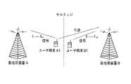
次に、図6を参照して、基地局装置BS_AのセルAと基地局装置BS_BのセルBとのセルエッジにおける各セルA,B間の干渉について説明する。マルチセルOFDMAシステムにおける通信では、基地局装置BS_AのセルA内のユーザ端末U_A1がセルエッジに位置している場合には、隣接する基地局装置BS_BのセルBのユーザ端末U_B1の信号により干渉を受けることが多い。 Next, with reference to FIG. 6, the interference between cells A and B at the cell edge between cell A of base station apparatus BS_A and cell B of base station apparatus BS_B will be described. In communication in the multi-cell OFDMA system, when the user terminal U_A1 in the cell A of the base station apparatus BS_A is located at the cell edge, the user terminal U_B1 in the cell B of the adjacent base station apparatus BS_B receives interference. There are many.
例えば、セルAとセルBとのセルエッジ近傍に位置しているセルAのユーザ端末U_A1が、キャリアf1・・・f64を用いて基地局装置BS_Aと通信し、セルBのユーザ端末U_B1が、キャリアf1・・・f128を用いて基地局装置BS_Bと通信している場合には、ユーザ端末U_A1とユーザ端末U_B1との間で重複しているキャリアf1・・・f64に載せられているユーザ端末U_B1の信号が、ユーザ端末U_A1の信号に重畳されて干渉を起こすことになる。この種の干渉は、CDMAシステムと異なり、干渉する信号のタイプが同じであるためガウシアン分布のノイズとみなすことはできない。このため、各ユーザ端末側の受信信号からユーザ端末ごとに干渉を除去しようとすると、ユーザ端末の回路構成が複雑になってしまう。For example, the user terminal U_A1 of the cell A located in the vicinity of the cell edge between the cell A and the cell B communicates with the base station apparatus BS_A using the carriers f1 ... F64 , and the user terminal U_B1 of the cell B , When the carrier f1 ... F128 is used for communication with the base station apparatus BS_B, the carrier f1 ... F64 is overlapped between the user terminal U_A1 and the user terminal U_B1. The signal of the user terminal U_B1 is superimposed on the signal of the user terminal U_A1 and causes interference. This kind of interference cannot be regarded as noise of Gaussian distribution because the type of interfering signal is the same as in a CDMA system. For this reason, if it is going to remove interference for every user terminal from the received signal of each user terminal side, the circuit structure of a user terminal will become complicated.
このような干渉を回避する方法として、隣接するそれぞれセルに予め異なる周波数のキャリアを割り当てる方法がある。そこで、このマルチセルOFDMAシステムでは、隣接するセルの各セクタに予め異なる周波数のキャリアを割り当てる方法を採用することが好ましい。 As a method for avoiding such interference, there is a method in which carriers having different frequencies are allocated to adjacent cells in advance. Therefore, in this multi-cell OFDMA system, it is preferable to employ a method in which carriers of different frequencies are allocated in advance to each sector of an adjacent cell.
そこで、このマルチセルOFDMAシステムでは、図3に示すように、ユーザ端末U_A1が位置するセルAを、3つのセクタA1,A2,A3に区分し、各セクタA1,A2,A3に、予めキャリアブロックf1〜64、f65〜128、・・・を割り当て、セクタA1のキャリアブロック群1が、キャリアブロックf1〜64・・・f257〜320、即ち{f1〜64・・・f257〜320}∈F1を有し、セクタA2のキャリアブロック群F2が、キャリアブロックf321〜384・・・f705〜768を有し、セクタA3のキャリアブロック群F3がキャリアブロックf769〜832・・・f961〜1024を有するというように、各セクタA1,A2,A3が、それぞれ異なるキャリアブロック群を有するようにする。また、各セクタA1,A2,A3の間のキャリアは直交するようにする。そして、セクタA1内のユーザ端末U_A1が、隣接するセルBのセクタB2、B3に接近した場合には、基地局装置BS_Bは、キャリアブロック群F2、F3をセクタB2、B3にそれぞれ割り当てる。Therefore, in this multi-cell OFDMA system, as shown in FIG. 3, the cell A in which the user terminal U_A1 is located is divided into three sectors A1, A2, and A3.1 to 64,f sixty-five to one hundred twenty-eight, assign a ..., carrier blocks 1 sector A1 is,
このような隣接するセルBの基地局装置BS_Bの連携処理により、セルエッジのユーザ端末U_A1は、隣接するセルBのユーザ端末U_B1の信号の干渉を受けることを回避することができる。なお、この方法では、基地局装置BS_AのセルAに隣接するセル
Bの基地局装置BS_Bが連携して動作することが必要である。このような基地局装置BS_A,BS_Bの連携処理は、基地局装置BS_A,BS_Bが共通の無線ネットワーク制御装置(RNC:Radio Network Controller )等に有線により接続されることによって実現可能となっている。By such cooperation processing of the base station device BS_B of the adjacent cell B, the user terminal U_A1 at the cell edge can avoid receiving signal interference of the user terminal U_B1 of the adjacent cell B. In this method, the base station device BS_B of the cell B adjacent to the cell A of the base station device BS_A needs to operate in cooperation. Such cooperation processing of the base station devices BS_A and BS_B can be realized by connecting the base station devices BS_A and BS_B to a common radio network controller (RNC: Radio Network Controller) or the like by wire.
このように、このマルチセルOFDMAシステムでは、上述の方法により、各セルにキャリアブロック群が割り当てられている。また、このマルチセルOFDMAシステムでは、システムのスペクトル効率が最高となるように、各セクタ内のユーザ端末Uへのキャリアブロックの割り当てが行われる。 Thus, in this multi-cell OFDMA system, a carrier block group is assigned to each cell by the method described above. In this multi-cell OFDMA system, carrier blocks are allocated to user terminals U in each sector so that the spectral efficiency of the system is maximized.
図7に、各ユーザ端末に割り当てられた異なるキャリアブロックの一例を示す。ところで、ユーザ端末が局部化FDMAシステムに接続する場合に鍵となる問題は、図7に示すように、伝送時間間隔ごとに、一定の基準(信号干渉雑音比SINRが最大等)以上の連続した数キャリアにより構成されたキャリアブロック(Chunck)を、いかにして各ユーザ端末に割り当て、かつ各ユーザ端末の業務サービス品質に対する要求を満たすかという点である。 FIG. 7 shows an example of different carrier blocks assigned to each user terminal. By the way, as shown in FIG. 7, the key problem when a user terminal is connected to a localized FDMA system is that a continuous time exceeding a certain standard (the signal interference noise ratio SINR is maximum, etc.) for each transmission time interval. This is the point of how to allocate a carrier block (Chunk) composed of several carriers to each user terminal and satisfy the requirements for the business service quality of each user terminal.
そこで、このマルチセルOFDMAシステムでは、例えば図6に示したように、セルエッジに位置するユーザ端末U_A1が隣接するセルBのユーザ端末U_B1の信号の干渉を受けることを回避するため、図3に示したように、ユーザ端末U_A1の属するセルAと隣接するセルBの間、又はユーザ端末U_A1の属するセクタA1と隣接するセルBの各セクタB2,B3の間に、直交するキャリアブロック群を割り当てて、互いに隣接するセル又はセクタの基地局装置BS_A,BS_Bの連携処理によってそれぞれの送信信号を直交させて干渉を除去する。 Therefore, in this multi-cell OFDMA system, as shown in FIG. 6, for example, the user terminal U_A1 located at the cell edge is shown in FIG. 3 in order to avoid receiving the signal interference of the user terminal U_B1 in the adjacent cell B. Thus, orthogonal carrier block groups are allocated between the cell A to which the user terminal U_A1 belongs and the adjacent cell B, or between the sectors A1 to which the user terminal U_A1 belongs and the sectors B2 and B3 of the adjacent cell B, Interference is removed by orthogonalizing the respective transmission signals by the cooperative processing of base station apparatuses BS_A and BS_B of cells or sectors adjacent to each other.
これにより、このマルチセルOFDMAシステムでは、図2で説明したように、キャリアのチャネル干渉雑音比SINRに基づいたキャリアスケジューリングを、キャリアのチャネル雑音比SNRに基づいたキャリア選択に転化することが可能になる。さらに、このマルチセルOFDMAシステムでは、各キャリア間の雑音電力の差が小さいという特徴を考慮して、キャリアスケジューリングの際に、キャリアのチャネルゲインに基づいてチャネル推定して、キャリア選択を一段と簡略化することが可能となる。 As a result, in this multi-cell OFDMA system, as described with reference to FIG. 2, it is possible to convert carrier scheduling based on carrier channel interference noise ratio SINR to carrier selection based on carrier channel noise ratio SNR. . Furthermore, in this multi-cell OFDMA system, in consideration of the feature that the noise power difference between carriers is small, channel estimation is performed based on the channel gain of the carrier during carrier scheduling, thereby further simplifying carrier selection. It becomes possible.
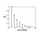
図8は、マルチパスの電力分布の例を示すグラフである。図8に示す計8つある各パスの電力は、指数関数減衰を示している。図8に示すように、各パスの電力を第1パスに正規化して得られる各パスの電力は、順に、[exp(0)、exp(−1)、exp(−2)、exp(−4)、exp(−5)、exp(−6)、exp(−7)]となる。 FIG. 8 is a graph illustrating an example of multipath power distribution. The power in each of the eight paths shown in FIG. 8 indicates exponential decay. As shown in FIG. 8, the power of each path obtained by normalizing the power of each path to the first path is [exp (0), exp (-1), exp (-2), exp (- 4), exp (-5), exp (-6), exp (-7)].
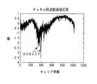
図9に、ユーザ端末Uに割り当てられるキャリアブロックのキャリアのチャネルゲインを示す。基地局装置BSから送信されたタイミングシンボルが図8に示す各パスを介して伝播された後の、推定されるキャリアのチャネルゲインは、例えば図9に示すようになる。このように、ユーザ端末Uに割り当てられるキャリアブロックの各キャリアは、一般にゲインの変動が大きく、フェージングが落ち込んでいるキャリアは、データ伝送性能が低下している。 In FIG. 9, the channel gain of the carrier of the carrier block allocated to the user terminal U is shown. The channel gain of the carrier estimated after the timing symbols transmitted from the base station apparatus BS are propagated through the paths shown in FIG. 8 is as shown in FIG. 9, for example. As described above, each carrier of the carrier block allocated to the user terminal U generally has a large gain variation, and a carrier in which fading is reduced has a reduced data transmission performance.
そこで、このマルチセルOFDMAシステムにおける基地局装置BSは、図10に示す方法により、ユーザ端末Uに対するキャリア割り当てを行う。 Therefore, the base station apparatus BS in this multi-cell OFDMA system performs carrier allocation to the user terminal U by the method shown in FIG.
すなわち、図10に示すように、まず、ユーザ端末Uは、マルチセルOFDMAシステムに接続する際に、基地局装置BSが送信したブロードキャスト情報を受信する(ステップS101)。そして、ユーザ端末Uは、受信したブロードキャスト情報に基づいて、基
地局装置BSに空きキャリアブロックが存在するか否か判断する(ステップS102)。ここで、基地局装置BSに空きキャリアブロックが存在しない場合は、接続失敗であるため、処理を終了する。That is, as shown in FIG. 10, first, the user terminal U receives broadcast information transmitted from the base station apparatus BS when connecting to the multi-cell OFDMA system (step S101). Then, the user terminal U determines whether or not there is a vacant carrier block in the base station apparatus BS based on the received broadcast information (step S102). Here, when there is no empty carrier block in the base station apparatus BS, the connection is unsuccessful, and the process is terminated.
ステップS102において、ユーザ端末Uが基地局装置SBに空きキャリアブロックが存在すると判断した場合には、マルチセルOFDMAシステムに接続する準備として、ユーザ端末Uは、同期に用いるタイミングシンボル及びパイロットシンボルを、空きキャリアを用いて基地局装置BSに送信する(ステップS103)。 In step S102, when the user terminal U determines that there is an empty carrier block in the base station apparatus SB, as a preparation for connection to the multi-cell OFDMA system, the user terminal U uses a timing symbol and a pilot symbol used for synchronization as empty. It transmits to base station apparatus BS using a carrier (step S103).
基地局装置BSは、ユーザ端末Uから送信されるパイロット信号を受信すると、当該パイロット信号を用いて、空きキャリアによって構成されるキャリアブロックの平均チャネルゲインを推定する(ステップS104)。 When the base station apparatus BS receives the pilot signal transmitted from the user terminal U, the base station apparatus BS estimates the average channel gain of the carrier block composed of vacant carriers using the pilot signal (step S104).
次いで、基地局装置BSは、推定した平均チャネルゲインにより、各キャリアブロックのチャネルゲインの大きさを比較し、チャネルゲインが大きいキャリアブロックをユーザ端末Uに割り当てる(ステップS105)。 Next, the base station apparatus BS compares the channel gains of the respective carrier blocks with the estimated average channel gain, and assigns a carrier block with a large channel gain to the user terminal U (step S105).
また、基地局装置BSは、ユーザ端末Uに割り当てたキャリアブロック内で各キャリアのチャネルゲインを比較して、チャネルゲインがある閾値よりも低いキャリアを選択し、このチャネルゲインがある閾値よりも低いキャリアではデータを伝送しないようにする(ステップS106)。 Also, the base station apparatus BS compares the channel gain of each carrier within the carrier block assigned to the user terminal U, selects a carrier whose channel gain is lower than a certain threshold, and this channel gain is lower than a certain threshold Data is not transmitted on the carrier (step S106).
そして、基地局装置BSは、上述のようにして、ユーザ端末Uへのキャリアの割り当てを終了すると、キャリアブロックのうちのチャネルゲインがある閾値以上のキャリアチャネルによりデータの伝送を開始する(ステップS107)。 When the base station apparatus BS finishes allocating the carrier to the user terminal U as described above, the base station apparatus BS starts data transmission using a carrier channel having a channel gain equal to or greater than a threshold value in the carrier block (step S107). ).
例えば、キャリア割り当てのターゲットとなるユーザ端末Uが、図3のセクタA1内に位置し、基地局装置BSがユーザ端末Uに対してキャリアf1〜f64が割り当て可能であるとする。基地局装置BSは、キャリアf1〜f64中の所定数のキャリアにより構成される1つ又は複数のキャリアブロックをいかにしてユーザ端末Uに割り当てるかという過程において、図10に示したキャリア割り当て方法を用いる。そして、基地局装置BSは、ユーザ端末Uに割り当てられたキャリアブロックのうち、チャネルゲインが前記閾値より低いキャリアによるデータを伝送しないようにしている。For example, a user terminal U as a carrier allocation targets, located within a sector A1 of FIG. 3, the base station apparatus BS to the carrier f1 ~f64 to the user terminal U is allocatable. The base station apparatus BS performs the carrier allocation shown in FIG. 10 in the process of how to allocate one or a plurality of carrier blocks constituted by a predetermined number of carriers in the carriers f1 to f64 to the user terminal U. Use the method. And base station apparatus BS is made not to transmit the data by the carrier whose channel gain is lower than the said threshold among the carrier blocks allocated to the user terminal U.
すなわち、このマルチセルOFDMAシステムにおけるキャリア割り当て方法は、基地局装置BSが、隣接するセクタに対して互いに直交するキャリアブロックを割り当てると共にユーザ端末Uに空きキャリアブロック情報を通知するステップと、ユーザ端末Uが前記空きキャリアを用いて既知シンボルを基地局装置BSに送信するステップと、基地局装置BSが、前記既知シンボルを受信し、前記既知シンボルを用いて、前記各空きキャリアブロックの平均チャネルゲインを推定するステップと、基地局装置BSが、各空きキャリアブロック間のチャネルゲインを比較し、前記平均チャネルゲインが大きいキャリアブロックを優先して、ユーザ端末Uが使用するキャリアブロックとして割り当てるステップと、基地局装置BSが、ユーザ端末に割り当てた前記キャリアブロック内で各キャリアのチャネルゲインを比較して、前記チャネルゲインが閾値よりも低いキャリアを選択し、このキャリアではデータを伝送しないようにするステップと、を具備している。 That is, the carrier allocation method in the multi-cell OFDMA system includes a step in which the base station apparatus BS allocates carrier blocks orthogonal to each other to adjacent sectors and notifies the user terminal U of empty carrier block information; A step of transmitting a known symbol to the base station apparatus BS using the vacant carrier, and the base station apparatus BS receives the known symbol and estimates an average channel gain of each vacant carrier block using the known symbol. The base station apparatus BS compares channel gains between the vacant carrier blocks, preferentially assigns carrier blocks having a large average channel gain, and assigns them as carrier blocks used by the user terminal U; The device BS is at the user end To within the carrier block allocated by comparing the channel gain of each carrier, the channel gain select a lower carrier than the threshold value, in the carrier is provided with a step to avoid transmit data.
また、基地局装置BSは、ユーザ端末Uに空きキャリアブロック情報を通知する通知部と、ユーザ端末Uによって前記空きキャリアブロックに配置され送信された既知シンボルを用いて、各空きキャリアブロックの平均チャネルゲインを推定する平均チャネルゲイン推定部と、各空きキャリアブロック間の平均チャネルゲインを比較し、前記平均チャネル
ゲインが大きいキャリアブロックを優先して、ユーザ端末Uが使用するキャリアブロックとして割り当てるキャリアブロック割り当て部と、を具備している。In addition, the base station apparatus BS uses the notification unit that notifies the user terminal U of the empty carrier block information, and the known symbols that are arranged and transmitted by the user terminal U in the empty carrier block, and the average channel of each empty carrier block An average channel gain estimator for estimating the gain, and an average channel gain between the vacant carrier blocks are compared, and a carrier block allocation to be assigned as a carrier block to be used by the user terminal U by giving priority to the carrier block having the large average channel gain And a portion.
なお、図10では、基地局装置BSがユーザ端末Uにキャリアを割り当てる過程を示したが、例えば、時分割多重(TDD:Time Division Duplex)動作モードでは、動作周波数は同一であって、上下方向のチャネル特性は相反性を有するため、基地局装置BS側のユーザ端末Uへのキャリア割り当てと、ユーザ端末U側の基地局装置BSへのキャリア割り当ては等価である。 In addition, in FIG. 10, although the process in which the base station apparatus BS allocates a carrier to the user terminal U was shown, in the time division multiplex (TDD) operation mode, the operation frequency is the same and the up-down direction Therefore, the carrier assignment to the user terminal U on the base station apparatus BS side and the carrier assignment to the base station apparatus BS on the user terminal U side are equivalent.
また、周波数分割多重(FDD:Frequency Division Duplex)動作モードでは、上下方向の特動作周波数は異なり、チャネル特性も異なるため、基地局装置BS側とユーザ端末U側とで個別にキャリアを割り当てる必要がある。実際には、このような基地局装置BS側とユーザ端末U側とで個別にキャリアを割り当てる操作は複雑であるため、上下のトラフィックの多寡に基づいて基地局装置BS側とユーザ端末U側とのいずれの側でキャリアの割り当てを行うかを決定すればよく、例えば主にユーザ端末Uが基地局装置BSからデータをダウンロードする場合には、基地局装置BS側でキャリアの割り当てを行えばよく、これにより下り回線の伝送品質を向上させることが可能となる。 In addition, in the frequency division duplex (FDD) operation mode, the special operation frequency in the vertical direction is different and the channel characteristics are also different. Therefore, it is necessary to individually assign carriers on the base station apparatus BS side and the user terminal U side. is there. Actually, since the operation of individually allocating carriers on the base station apparatus BS side and the user terminal U side is complicated, the base station apparatus BS side, the user terminal U side, Which side of the carrier is to be assigned the carrier, for example, when the user terminal U mainly downloads data from the base station apparatus BS, the base station apparatus BS may perform the carrier assignment. This makes it possible to improve downlink transmission quality.
ところで、基地局装置BSは、前述したように、OFDM通信を行う際に、まずタイミング同期パイロットシンボルを送信し、その後に、パイロットキャリア上に分散的にマッピングされた、チャネル推定に用いるパイロットシンボルを送信する。キャリア割り当てを行う場合の条件は、チャネルゲインが既知であることであるが、ユーザ端末Uが最初にチャネルに接続する際にはチャネル推定値は未知であるため、ユーザ端末Uにキャリアブロックを割り当てることができない。 By the way, as described above, when performing OFDM communication, the base station apparatus BS first transmits a timing synchronization pilot symbol, and then transmits pilot symbols used for channel estimation that are distributedly distributed on the pilot carrier. Send. The condition for carrier allocation is that the channel gain is known, but when the user terminal U first connects to the channel, the channel estimation value is unknown, so a carrier block is allocated to the user terminal U. I can't.
そこで、このマルチセルOFDMAシステムにおける基地局装置BSでは、最初に、ユーザ端末Uから受信したタイミングシンボルを直接用いて、最小平均二乗誤差法によりチャネルゲインを推定する。例えば、送信周波数領域タイミング信号をXP(n)とすると、周波数領域受信タイミング信号は、YP=XPHP+Wとなり、最小二乗(LS)を用いてチャネルゲインを推定する。つまり、以下の式(1)で示す推定誤差のユークリッド距離が最小になるようにする。
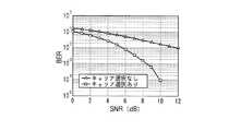
図11に、キャリアのチャネルゲインに基づいてキャリアの選択を行った後のシステムビットエラーレート(BER:Bit Error Rate)性能を示す。図11に示すシミュレーションパラメータは、それぞれBPSK(Binariphase Phase Shift Keying)変調、未符号化;8パスチャネル、各パスのチャネル電力は指数関数減衰を示し(図8参照)、1つのキャリアブロック(64本のキャリア)をユーザ端末Uに割り当て、選択した“ゼロ”キャリアの数は12である。 FIG. 11 shows system bit error rate (BER) performance after carrier selection based on the channel gain of the carrier. The simulation parameters shown in FIG. 11 are BPSK (Binariphase Phase Shift Keying) modulation, uncoded; 8-path channel, channel power of each path indicates exponential decay (see FIG. 8), one carrier block (64 lines) The number of selected “zero” carriers is twelve.
図11に示すように、上述したキャリア割り当て方法により、フェージングが落ち込んでいるキャリアではデータを送信しないようにすることにより、対BER性能を改善できることが理解される。この場合、これらのフェージングが落ち込んでいるキャリアは使用されずに周波数を消費するが、これを問題にしなければ、キャリアブロックの平均チャネルゲインは向上しているので、このマルチセルOFDMAシステムにおける基地局装置BSでは、より高次の変調方式を用いて伝送レートやスペクトル効率を向上させることが可能となる。 As shown in FIG. 11, it is understood that the BER performance can be improved by not transmitting data on a carrier in which fading is reduced by the above-described carrier allocation method. In this case, the carrier in which fading is reduced is not used and consumes a frequency. If this is not a problem, the average channel gain of the carrier block is improved. Therefore, the base station apparatus in this multi-cell OFDMA system In the BS, it is possible to improve the transmission rate and spectral efficiency by using a higher-order modulation scheme.
本発明に係るマルチセル直交周波数分割多元接続システムにおけるキャリア割り当て方法の1つの態様は、基地局装置が、隣接するセクタに対して互いに直交するキャリアブロックを割り当てると共に端末装置に空きキャリアブロック情報を通知するステップと、端末装置が前記空きキャリアを用いて既知シンボルを前記基地局装置に送信するステップと、前記基地局装置が、前記既知シンボルを受信し、前記既知シンボルを用いて、前記各空きキャリアブロックの平均チャネルゲインを推定するステップと、前記基地局装置が、各空きキャリアブロック間のチャネルゲインを比較し、前記平均チャネルゲインが大きいキャリアブロックを優先して、前記端末装置が使用するキャリアブロックとして割り当てるステップと、前記基地局装置が、前記移動端末装置に割り当てた前記キャリアブロック内で各キャリアのチャネルゲインを比較して、前記チャネルゲインが閾値よりも低いキャリアを選択し、このキャリアではデータを伝送しないようにするステップと、を具備する構成を採る。 One aspect of the carrier allocation method in the multi-cell orthogonal frequency division multiple access system according to the present invention is that the base station apparatus allocates carrier blocks orthogonal to each other to adjacent sectors and notifies the terminal apparatus of empty carrier block information. A step in which a terminal apparatus transmits a known symbol to the base station apparatus using the empty carrier, and the base station apparatus receives the known symbol and uses the known symbol to each of the empty carrier blocks. The base station apparatus compares the channel gains between the vacant carrier blocks, preferentially selects the carrier block having a large average channel gain, and sets the carrier block to be used by the terminal apparatus. Assigning, and the base station device Comparing the channel gain of each carrier in the carrier block allocated to the mobile terminal apparatus, selecting a carrier having a channel gain lower than a threshold, and not transmitting data on this carrier. The structure to do is taken.
この構成によれば、前記基地局装置が、前記平均チャネルゲインが大きいキャリアブロックを優先して、前記端末装置が使用するキャリアブロックとして割り当て、前記移動端末装置に割り当てた前記チャネルゲインが閾値よりも低いキャリアではデータを伝送しないようにしているので、システム容量及びビットエラーレート性能を向上させることができる。 According to this configuration, the base station apparatus gives priority to a carrier block having a large average channel gain and assigns it as a carrier block to be used by the terminal apparatus, and the channel gain assigned to the mobile terminal apparatus is lower than a threshold value. Since data is not transmitted on a low carrier, system capacity and bit error rate performance can be improved.
本発明に係るキャリア割り当て方法の1つの態様は、前記端末装置への前記キャリアブロックの割り当て終了後、前記チャネルゲインが前記閾値よりも低いキャリア以外のキャリアチャネルで前記基地局装置がデータの伝送を開始するステップ、をさらに具備する構成を採る。 One aspect of the carrier allocation method according to the present invention is that, after the allocation of the carrier block to the terminal apparatus is completed, the base station apparatus transmits data on a carrier channel other than a carrier whose channel gain is lower than the threshold. And a starting step.
この構成によれば、前記基地局装置は、前記チャネルゲインが前記閾値よりも低いキャリア以外のキャリアチャネルでデータの伝送を開始するので、システム容量及びビットエラーレート性能を向上させることができる。 According to this configuration, the base station apparatus starts data transmission on a carrier channel other than the carrier whose channel gain is lower than the threshold, so that the system capacity and the bit error rate performance can be improved.
本発明に係るキャリア割り当て方法の1つの態様は、前記端末装置のマルチセル直交周波数分割多元接続システムへの接続が一回目である場合には、前記既知シンボルとしてタイミングシンボルを使用して前記チャネルゲインを推定し、前記端末装置の前記マルチセル直交周波数分割多元接続システムへの接続が一回目以外の場合には、前記既知シンボルとしてパイロットシンボルを使用して前記チャネルゲインを推定する、構成を採る。 One aspect of the carrier allocation method according to the present invention is that, when the terminal device is connected to the multi-cell orthogonal frequency division multiple access system for the first time, the channel gain is set using a timing symbol as the known symbol. When the terminal device is connected to the multi-cell orthogonal frequency division multiple access system other than the first time, the channel gain is estimated using a pilot symbol as the known symbol.
端末装置が最初にチャネルに接続する際にはチャネル推定値は未知であるため、チャネルゲインが既知でないと端末装置にキャリアブロックを割り当てることができない。この構成によれば、接続が一回目である場合には、前記既知シンボルとしてタイミングシンボルを使用して前記チャネルゲインを推定しているので、システム容量及びビットエラーレート性能を向上させることができるキャリアブロックを端末装置に割り当てることができる。 When the terminal device first connects to the channel, the channel estimation value is unknown, and therefore the carrier block cannot be assigned to the terminal device unless the channel gain is known. According to this configuration, when the connection is the first time, the channel gain is estimated using the timing symbol as the known symbol, so that the carrier capable of improving the system capacity and the bit error rate performance Blocks can be assigned to terminal devices.
本発明に係るキャリア割り当て方法の1つの態様は、最小平均二乗誤差法を用いて前記チャネルゲインを推定する、構成を採る。 One aspect of the carrier allocation method according to the present invention employs a configuration in which the channel gain is estimated using a minimum mean square error method.
この構成によれば、前記チャネルゲインを、最小平均二乗誤差法を用いて推定することができる。 According to this configuration, the channel gain can be estimated using the minimum mean square error method.
本発明に係るキャリア割り当て方法の1つの態様は、前記閾値は、前記平均チャネルゲインの半値である、構成を採る。 One aspect of the carrier allocation method according to the present invention employs a configuration in which the threshold is a half value of the average channel gain.
この構成によれば、前記平均チャネルゲインの半値よりもチャネルゲインが低いキャリアによりデータを伝送しないようにすることができる。 According to this configuration, data can be prevented from being transmitted by a carrier having a channel gain lower than the half value of the average channel gain.
本発明に係るキャリア割り当て方法の1つの態様は、前記マルチセル直交周波数分割多元接続システムは、マルチセル・局部化周波数分割多元接続システムである、構成を採る。 One aspect of the carrier allocation method according to the present invention employs a configuration in which the multi-cell orthogonal frequency division multiple access system is a multi-cell / localized frequency division multiple access system.
この構成によれば、局部化FDMAの伝送方式を用いているので、スケジューリングアルゴリズムを用いてOFDMシンボルにおける全キャリアの、連続している一部分のキャリアをユーザ端末に割り当てることができる。 According to this configuration, since a localized FDMA transmission method is used, a continuous part of all the carriers in the OFDM symbol can be allocated to the user terminal using a scheduling algorithm.
本発明に係るキャリア割り当て方法の1つの態様は、前記マルチセル直交周波数分割多元接続システムは、マルチセル・分散型周波数分割多元接続システムである、構成を採る。 One aspect of the carrier allocation method according to the present invention employs a configuration in which the multi-cell orthogonal frequency division multiple access system is a multi-cell / distributed frequency division multiple access system.
この構成によれば、分散型FDMAの伝送方式を用いているので、各タイムスロットで、ユーザ端末に割り当てるキャリアをOFDMシンボルの全ての周波数領域のキャリアに分散させることができる。 According to this configuration, since the distributed FDMA transmission scheme is used, the carrier allocated to the user terminal can be distributed to all the frequency domain carriers of the OFDM symbol in each time slot.
本発明に係るキャリア割り当て方法の1つの態様は、前記マルチセル直交周波数分割多元接続システムは、周波数分割多重方式の動作モードで動作し、上下方向の回線のトラフィックに基づいて何れの方式がキャリアの割り当てを行うかを決定し、前記端末装置が前記基地局装置からデータをダウンロードする場合には前記基地局装置でキャリアの割り当てを行い、前記端末装置が前記基地局装置に対してデータをアップロードする場合には前記端末装置でキャリアの割り当てを行う、構成を採る。 One aspect of the carrier allocation method according to the present invention is that the multi-cell orthogonal frequency division multiple access system operates in an operation mode of a frequency division multiplexing scheme, and any scheme is assigned to a carrier based on traffic in a vertical line. When the terminal device downloads data from the base station device, the base station device performs carrier allocation, and the terminal device uploads data to the base station device Adopts a configuration in which a carrier is allocated by the terminal device.
この構成によれば、上下のトラフィックの多寡に基づいて前記基地局装置と前記端末装
置とのいずれの側でキャリアの割り当てを行うかを決定できるので、下り回線の伝送品質を向上させることが可能となる。According to this configuration, it is possible to determine on which side of the base station apparatus or the terminal apparatus the carrier allocation is performed based on the amount of upper and lower traffic, so that it is possible to improve downlink transmission quality It becomes.
本発明に係るキャリア割り当て方法の1つの態様は、前記マルチセル直交周波数分割多元接続システムは、時分割多重方式の動作モードで動作し,前記基地局装置又は前記端末装置によりキャリアの割り当てを行う、構成を採る。 One aspect of a carrier allocation method according to the present invention is a configuration in which the multi-cell orthogonal frequency division multiple access system operates in an operation mode of a time division multiplexing scheme and performs carrier allocation by the base station apparatus or the terminal apparatus. Take.
この構成によれば、時分割多重方式の動作モードで動作するので、動作周波数は同一であって、上下方向のチャネル特性は相反性を有するため、基地局装置側の端末装置へのキャリア割り当てと、端末装置側の基地局装置へのキャリア割り当てが等価となり、キャリアの割り当てを簡易に行うことができる。 According to this configuration, since the operation is performed in the operation mode of the time division multiplexing method, the operation frequency is the same, and the channel characteristics in the vertical direction have reciprocity. Thus, carrier assignment to the base station device on the terminal device side is equivalent, and carrier assignment can be performed easily.
本発明に係る基地局装置の1つの態様は、端末装置に空きキャリアブロック情報を通知する通知部と、前記端末装置によって前記空きキャリアブロックに配置され送信された既知シンボルを用いて、各空きキャリアブロックの平均チャネルゲインを推定する平均チャネルゲイン推定部と、各空きキャリアブロック間の平均チャネルゲインを比較し、前記平均チャネルゲインが大きいキャリアブロックを優先して、前記端末装置が使用するキャリアブロックとして割り当てるキャリアブロック割り当て部と、を具備する構成を採る。 One aspect of the base station apparatus according to the present invention is that each empty carrier is transmitted using a notification unit that notifies the terminal apparatus of empty carrier block information and a known symbol that is arranged and transmitted by the terminal apparatus in the empty carrier block. An average channel gain estimation unit that estimates an average channel gain of a block is compared with an average channel gain between vacant carrier blocks, and a carrier block having a large average channel gain is given priority as a carrier block used by the terminal device. The carrier block allocating unit to be allocated is employed.
この構成によれば、前記平均チャネルゲインが大きいキャリアブロックを優先して、前記端末装置が使用するキャリアブロックとして割り当てることができる。 According to this configuration, a carrier block having a large average channel gain can be preferentially assigned as a carrier block used by the terminal device.
本発明に係る基地局装置の1つの態様は、前記端末装置に割り当てたキャリアブロック内の各キャリアのうち、所定の閾値よりも低いキャリアを検出するキャリア検出部を、さらに具備し、前記所定の閾値よりも低いキャリアからはデータを伝送しない、構成を採る。 One aspect of the base station apparatus according to the present invention further comprises a carrier detection unit that detects a carrier lower than a predetermined threshold among the carriers in the carrier block allocated to the terminal apparatus, A configuration is adopted in which data is not transmitted from a carrier lower than the threshold value.
この構成によれば、前記移動端末装置に割り当てた前記チャネルゲインが閾値よりも低いキャリアではデータを伝送しないようにしているので、システム容量及びビットエラーレート性能を向上させることができる。 According to this configuration, data is not transmitted on a carrier whose channel gain assigned to the mobile terminal apparatus is lower than a threshold value, so that system capacity and bit error rate performance can be improved.
本発明に係る基地局装置の1つの態様は、通信確立前に、前記通知部、前記平均チャネルゲイン推定部、前記キャリアブロック割り当て部による処理を行い、通信確立後に、所定の閾値以上のキャリアからデータを伝送する、構成を採る。 One aspect of the base station apparatus according to the present invention performs processing by the notifying unit, the average channel gain estimating unit, and the carrier block allocating unit before establishing communication, and after communication is established, from a carrier having a predetermined threshold value or more. Adopt a configuration to transmit data.
この構成によれば、前記チャネルゲインが前記閾値よりも低いキャリア以外のキャリアチャネルでデータの伝送を開始するので、システム容量及びビットエラーレート性能を向上させることができる。 According to this configuration, since data transmission is started on a carrier channel other than the carrier whose channel gain is lower than the threshold value, system capacity and bit error rate performance can be improved.
2005年11月17日の中国出願第200510125462.7に含まれる明細書、図面および要約書の開示内容は、すべて本願に援用される。 The disclosure of the specification, drawings and abstract contained in Chinese application No. 2005101255462.7 of November 17, 2005 is hereby incorporated by reference.
本発明に係るマルチセル直交周波数分割多元接続システムにおけるキャリア割り当て方法は、平均チャネルゲインが大きいキャリアブロックを優先して、端末装置が使用するキャリアブロックとして割り当てて、システム容量及びビットエラーレート性能を向上させることができるので、直交周波数分割多重技術を用いた、無線LAN、固定無線接続、移動体通信、地上デジタルテレビジョン放送等の、情報伝送システム及びそれに対応する通信方法の、マルチセル直交周波数分割多元接続システムにおけるキャリア割り当て方法として有用である。 A carrier allocation method in a multi-cell orthogonal frequency division multiple access system according to the present invention gives priority to a carrier block having a large average channel gain and allocates it as a carrier block used by a terminal device, thereby improving system capacity and bit error rate performance. Multi-cell orthogonal frequency division multiple access for information transmission systems and corresponding communication methods such as wireless LAN, fixed wireless connection, mobile communication, digital terrestrial television broadcasting, etc. using orthogonal frequency division multiplexing technology This is useful as a carrier allocation method in the system.
Claims (10)
Translated fromJapanese端末装置が前記空きキャリアを用いて既知シンボルを前記基地局装置に送信するステップと、
前記基地局装置が、前記既知シンボルを受信し、前記既知シンボルを用いて、前記各空きキャリアブロックの平均チャネルゲインを推定するステップと、
前記基地局装置が、各空きキャリアブロック間のチャネルゲインを比較し、前記平均チャネルゲインが大きいキャリアブロックを優先して、前記端末装置が使用するキャリアブロックとして割り当てるステップと、
前記基地局装置が、前記移動端末装置に割り当てた前記キャリアブロック内で各キャリアのチャネルゲインを比較して、前記チャネルゲインが閾値よりも低いキャリアを選択し、このキャリアではデータを伝送しないようにするステップと、
を具備するマルチセル直交周波数分割多元接続システムにおけるキャリア割り当て方法。A step of the base station apparatus allocating carrier blocks orthogonal to each other to adjacent sectors and notifying the terminal apparatus of empty carrier block information;
A terminal device transmitting a known symbol to the base station device using the empty carrier;
The base station apparatus receiving the known symbol and using the known symbol to estimate an average channel gain of each vacant carrier block;
The base station device compares channel gains between the empty carrier blocks, preferentially assigns carrier blocks having a large average channel gain, and assigns them as carrier blocks used by the terminal device;
The base station apparatus compares the channel gain of each carrier in the carrier block allocated to the mobile terminal apparatus, selects a carrier whose channel gain is lower than a threshold, and does not transmit data on this carrier And steps to
A carrier allocation method in a multi-cell orthogonal frequency division multiple access system comprising:
をさらに具備する請求項1に記載のキャリア割り当て方法。After the end of assignment of the carrier block to the terminal device, the base station device starts transmitting data on a carrier channel other than the carrier whose channel gain is lower than the threshold;
The carrier allocation method according to claim 1, further comprising:
請求項1に記載のキャリア割り当て方法。Estimating the channel gain using a least mean square error method;
The carrier allocation method according to claim 1.
請求項1に記載のキャリア割り当て方法。The threshold is a half value of the average channel gain.
The carrier allocation method according to claim 1.
請求項1に記載のキャリア割り当て方法。The multi-cell orthogonal frequency division multiple access system is a multi-cell / localized frequency division multiple access system,
The carrier allocation method according to claim 1.
請求項1に記載のキャリア割り当て方法。The multi-cell orthogonal frequency division multiple access system is a multi-cell / distributed frequency division multiple access system,
The carrier allocation method according to claim 1.
前記端末装置によって前記空きキャリアブロックに配置され送信された既知シンボルを用いて、各空きキャリアブロックの平均チャネルゲインを推定する平均チャネルゲイン推定部と、
各空きキャリアブロック間の平均チャネルゲインを比較し、前記平均チャネルゲインが大きいキャリアブロックを優先して、前記端末装置が使用するキャリアブロックとして割り当てるキャリアブロック割り当て部と、
を具備する基地局装置。A notification unit for notifying the terminal device of empty carrier block information;
An average channel gain estimator for estimating an average channel gain of each vacant carrier block using a known symbol arranged and transmitted in the vacant carrier block by the terminal device;
A carrier block allocating unit that compares the average channel gain between each empty carrier block, prioritizes the carrier block having a large average channel gain, and allocates the carrier block used by the terminal device;
A base station apparatus comprising:
請求項8に記載の基地局装置。A carrier detection unit for detecting a carrier lower than a predetermined threshold among the carriers in the carrier block allocated to the terminal device is further provided, and data is not transmitted from a carrier lower than the predetermined threshold.
The base station apparatus according to claim 8.
通信確立後に、所定の閾値以上のキャリアからデータを伝送する、
請求項9に記載の基地局装置。Before establishing communication, perform processing by the notification unit, the average channel gain estimation unit, the carrier block allocation unit,
After communication is established, data is transmitted from a carrier having a predetermined threshold value or more.
The base station apparatus according to claim 9.
Applications Claiming Priority (3)
| Application Number | Priority Date | Filing Date | Title |
|---|---|---|---|
| CNA2005101254627ACN1968239A (en) | 2005-11-17 | 2005-11-17 | Carrier allocation method for multi-cell orthogonal frequency division multiple address system |
| CN200510125462.7 | 2005-11-17 | ||
| PCT/JP2006/322883WO2007058270A1 (en) | 2005-11-17 | 2006-11-16 | Carrier allocation method in multi cell orthogonal frequency division multiple access system |
Publications (2)
| Publication Number | Publication Date |
|---|---|
| JPWO2007058270A1 JPWO2007058270A1 (en) | 2009-05-07 |
| JP4864008B2true JP4864008B2 (en) | 2012-01-25 |
Family
ID=38048654
Family Applications (1)
| Application Number | Title | Priority Date | Filing Date |
|---|---|---|---|
| JP2007545294AExpired - Fee RelatedJP4864008B2 (en) | 2005-11-17 | 2006-11-16 | Carrier allocation method in multi-cell orthogonal frequency division multiple access system |
Country Status (4)
| Country | Link |
|---|---|
| US (1) | US8009549B2 (en) |
| JP (1) | JP4864008B2 (en) |
| CN (1) | CN1968239A (en) |
| WO (1) | WO2007058270A1 (en) |
Families Citing this family (29)
| Publication number | Priority date | Publication date | Assignee | Title |
|---|---|---|---|---|
| US7817735B2 (en)* | 2006-01-11 | 2010-10-19 | Amicus Wireless Technology Ltd. | Device and method of performing channel estimation for OFDM-based wireless communication system |
| BRPI0721890A2 (en)* | 2007-08-02 | 2011-05-03 | Fujitsu Ltd | Pilot arrangement method in mobile radio communication system and transmitter / receiver adopting the same |
| CN101364846B (en)* | 2007-08-07 | 2011-12-07 | 中兴通讯股份有限公司 | Sub-carrier noise power estimation method based on pilot |
| JP5060933B2 (en)* | 2007-12-12 | 2012-10-31 | Kddi株式会社 | Radio frame control apparatus, radio frame control method, and radio communication apparatus |
| WO2009135516A1 (en)* | 2008-05-09 | 2009-11-12 | Nokia Siemens Networks Oy | Multi-cell channel estimation in 3g-lte based virtual pilot sequences |
| CN101384067B (en)* | 2008-10-17 | 2011-12-07 | 京信通信系统(中国)有限公司 | Carrier channel router |
| CN101494490B (en)* | 2009-01-04 | 2012-10-17 | 北京邮电大学 | Feedback-based random distributed self-organizing communication method and system |
| CN101772034B (en)* | 2009-01-04 | 2013-04-17 | 华为技术有限公司 | Method, related equipment and system for determining interference priorities of neighbor cells |
| CN101478342B (en)* | 2009-01-22 | 2013-04-03 | 清华大学 | Method for cooperative scheduling between multiple districts in multi-antenna cellular communication system |
| US8811903B2 (en) | 2009-05-28 | 2014-08-19 | Microsoft Corporation | Spectrum assignment for networks over white spaces and other portions of the spectrum |
| JP5310505B2 (en)* | 2009-11-25 | 2013-10-09 | 富士通株式会社 | Wireless communication method, base station, and mobile communication terminal |
| JP5668314B2 (en)* | 2010-04-05 | 2015-02-12 | 住友電気工業株式会社 | Base station equipment |
| WO2011118577A1 (en)* | 2010-03-23 | 2011-09-29 | 住友電気工業株式会社 | Base station device and terminal device |
| CN101827063B (en)* | 2010-04-07 | 2012-08-29 | 北京邮电大学 | Frequency multiplexing device and method of OFDMA (Orthogonal Frequency Division Multiplexing Access) system |
| US8406694B2 (en)* | 2010-06-11 | 2013-03-26 | Microsoft Corporation | Channel discovery protocol |
| JP5466311B2 (en) | 2010-12-24 | 2014-04-09 | 三菱電機株式会社 | Receiving apparatus and method |
| CN102355718B (en)* | 2011-08-08 | 2013-12-18 | 中国科学技术大学 | Method for coordinating uplink interference by combining high interference indication and overload indication |
| US8774066B2 (en)* | 2012-05-31 | 2014-07-08 | Intel Mobile Communications GmbH | Macro-femto inter-cell interference mitigation |
| CN102833057B (en)* | 2012-08-10 | 2015-06-17 | 宁波大学 | Multi-user OFDM (orthogonal frequency division multiplexing) resource allocation method |
| GB2505900B (en)* | 2012-09-13 | 2015-03-04 | Broadcom Corp | Methods, apparatus and computer programs for operating a wireless communications device |
| US10362081B2 (en)* | 2013-08-30 | 2019-07-23 | Citrix Systems, Inc. | Methods and systems for quantifying the holistic quality of experience for internet multimedia |
| CA2855136C (en) | 2014-04-07 | 2019-01-29 | Marin Litoiu | Systems and methods of precision sharing of big data |
| CN105282075B (en)* | 2014-06-10 | 2019-03-29 | 中兴通讯股份有限公司 | The suppressing method and device of beat frequency noise |
| CN106604287B (en)* | 2015-10-20 | 2019-09-17 | 上海诺基亚贝尔股份有限公司 | A kind of wireless communications method and equipment |
| CN105682236A (en)* | 2016-03-04 | 2016-06-15 | 金陵科技学院 | Power minimized subcarrier distribution algorithm |
| CN107302800A (en)* | 2016-04-15 | 2017-10-27 | 索尼公司 | Apparatus and method for mixing multiple access wireless communication system |
| WO2021029015A1 (en)* | 2019-08-13 | 2021-02-18 | 日本電信電話株式会社 | Wireless communication system and wireless communication method |
| CN113163419B (en)* | 2021-02-22 | 2022-07-22 | 国网山东省电力公司平邑县供电公司 | A resource scheduling system for high-speed overlay network of power system |
| US20230122884A1 (en)* | 2021-10-20 | 2023-04-20 | Nishith Tripathi | System and method for licensed spectrum coordination |
Citations (7)
| Publication number | Priority date | Publication date | Assignee | Title |
|---|---|---|---|---|
| JP2002111627A (en)* | 2000-08-01 | 2002-04-12 | Sony Internatl Europ Gmbh | Cellular communication system and information transmission method |
| JP2004523934A (en)* | 2000-10-10 | 2004-08-05 | ブロードストーム テレコミュニケイションズ インコーポレイテッド | Medium access control for orthogonal frequency division multiple access (OFDMA) cellular networks |
| JP2004529524A (en)* | 2000-12-15 | 2004-09-24 | ブロードストーム テレコミュニケイションズ インコーポレイテッド | Multi-carrier communication by adaptive cluster configuration and switching |
| WO2004105294A2 (en)* | 2003-05-14 | 2004-12-02 | Qualcomm, Incorporated | Power control and scheduling in an ofdm system |
| JP2004537875A (en)* | 2000-12-15 | 2004-12-16 | ブロードストーム テレコミュニケイションズ インコーポレイテッド | Multi-carrier communication with group-based subcarrier allocation |
| JP2005502218A (en)* | 2000-12-15 | 2005-01-20 | ブロードストーム テレコミュニケイションズ インコーポレイテッド | OFDMA with adaptive subcarrier-cluster configuration and selective loading |
| JP2005142935A (en)* | 2003-11-07 | 2005-06-02 | Toshiba Corp | Wireless communication system, wireless control method, and control apparatus |
Family Cites Families (8)
| Publication number | Priority date | Publication date | Assignee | Title |
|---|---|---|---|---|
| CN1092436C (en) | 1995-06-14 | 2002-10-09 | 国际商业机器公司 | Packet data transmission in code-division multipel access communication systems |
| EP0832527B1 (en)* | 1995-06-14 | 1999-05-19 | International Business Machines Corporation | Packet data transmission in code-division multiple access communication systems |
| US6539063B1 (en) | 1999-02-18 | 2003-03-25 | Ibiquity Digital Corporation | System and method for recovering symbol timing offset and carrier frequency error in an OFDM digital audio broadcast system |
| EP1755256B1 (en) | 2001-03-09 | 2010-04-28 | QUALCOMM Incorporated | Method of Symbol timing synchronization in communication systems |
| JP2003087023A (en)* | 2001-09-13 | 2003-03-20 | Toshiba Corp | Portable information equipment with built-in wireless communication antenna |
| KR100965338B1 (en) | 2003-08-18 | 2010-06-22 | 엘지전자 주식회사 | Subcarrier Allocation Method for Inter-cell Interference Reduction in PFDMA Cellular Environment |
| KR100557158B1 (en)* | 2003-11-12 | 2006-03-03 | 삼성전자주식회사 | Apparatus and Method for Subcarrier Allocation in Mobile Communication System Using Orthogonal Frequency Division Multiplexing |
| KR100922948B1 (en)* | 2004-03-11 | 2009-10-22 | 삼성전자주식회사 | Pilot-aided channel estimation technique in uplink ofdma system |
- 2005
- 2005-11-17CNCNA2005101254627Apatent/CN1968239A/enactivePending
- 2006
- 2006-11-16WOPCT/JP2006/322883patent/WO2007058270A1/ennot_activeCeased
- 2006-11-16JPJP2007545294Apatent/JP4864008B2/ennot_activeExpired - Fee Related
- 2006-11-16USUS12/092,950patent/US8009549B2/enactiveActive
Patent Citations (7)
| Publication number | Priority date | Publication date | Assignee | Title |
|---|---|---|---|---|
| JP2002111627A (en)* | 2000-08-01 | 2002-04-12 | Sony Internatl Europ Gmbh | Cellular communication system and information transmission method |
| JP2004523934A (en)* | 2000-10-10 | 2004-08-05 | ブロードストーム テレコミュニケイションズ インコーポレイテッド | Medium access control for orthogonal frequency division multiple access (OFDMA) cellular networks |
| JP2004529524A (en)* | 2000-12-15 | 2004-09-24 | ブロードストーム テレコミュニケイションズ インコーポレイテッド | Multi-carrier communication by adaptive cluster configuration and switching |
| JP2004537875A (en)* | 2000-12-15 | 2004-12-16 | ブロードストーム テレコミュニケイションズ インコーポレイテッド | Multi-carrier communication with group-based subcarrier allocation |
| JP2005502218A (en)* | 2000-12-15 | 2005-01-20 | ブロードストーム テレコミュニケイションズ インコーポレイテッド | OFDMA with adaptive subcarrier-cluster configuration and selective loading |
| WO2004105294A2 (en)* | 2003-05-14 | 2004-12-02 | Qualcomm, Incorporated | Power control and scheduling in an ofdm system |
| JP2005142935A (en)* | 2003-11-07 | 2005-06-02 | Toshiba Corp | Wireless communication system, wireless control method, and control apparatus |
Also Published As
| Publication number | Publication date |
|---|---|
| WO2007058270A1 (en) | 2007-05-24 |
| JPWO2007058270A1 (en) | 2009-05-07 |
| US20090122887A1 (en) | 2009-05-14 |
| US8009549B2 (en) | 2011-08-30 |
| CN1968239A (en) | 2007-05-23 |
Similar Documents
| Publication | Publication Date | Title |
|---|---|---|
| JP4864008B2 (en) | Carrier allocation method in multi-cell orthogonal frequency division multiple access system | |
| US9490954B2 (en) | Method and apparatus for allocating a control channel resource of a relay node in a backhaul subframe | |
| EP1492280B1 (en) | Quality driven adaptive channel assignment in an OFDMA radio communication system | |
| CN101406080B (en) | Method & system for fractional frequency reuse in a wireless communication network | |
| EP1917755B1 (en) | Segment sensitive scheduling | |
| KR100929094B1 (en) | System and method for dynamic resource allocation in a communication system using orthogonal frequency division multiple access scheme | |
| CN102057702B (en) | Method and system for providing uplink structure and minimizing pilot signal overhead in a wireless communication network | |
| CN1879325B (en) | Apparatus and method for transmitting and receiving common control information in wireless communication system | |
| US20080151743A1 (en) | Radio Access System and Method Using Ofdm and Cdma for Broadband Data Transmission | |
| US20060268983A1 (en) | Method for configuring and managing channels in a wireless communication system using AMC channels and diversity channels, transmission/reception apparatus thereof, and system thereof | |
| KR20050029082A (en) | System and method for dynamic resource allocation in communication system using orthogonal frequency division multiple access scheme | |
| CN100466799C (en) | A method for multiplexing of soft frequency | |
| KR101655788B1 (en) | Method and apparatus for managing control channel based on user equipment feedback in wireless communication system |
Legal Events
| Date | Code | Title | Description |
|---|---|---|---|
| A621 | Written request for application examination | Free format text:JAPANESE INTERMEDIATE CODE: A621 Effective date:20090602 | |
| TRDD | Decision of grant or rejection written | ||
| A01 | Written decision to grant a patent or to grant a registration (utility model) | Free format text:JAPANESE INTERMEDIATE CODE: A01 Effective date:20111025 | |
| A01 | Written decision to grant a patent or to grant a registration (utility model) | Free format text:JAPANESE INTERMEDIATE CODE: A01 | |
| A61 | First payment of annual fees (during grant procedure) | Free format text:JAPANESE INTERMEDIATE CODE: A61 Effective date:20111108 | |
| FPAY | Renewal fee payment (event date is renewal date of database) | Free format text:PAYMENT UNTIL: 20141118 Year of fee payment:3 | |
| R150 | Certificate of patent or registration of utility model | Free format text:JAPANESE INTERMEDIATE CODE: R150 | |
| R250 | Receipt of annual fees | Free format text:JAPANESE INTERMEDIATE CODE: R250 | |
| R250 | Receipt of annual fees | Free format text:JAPANESE INTERMEDIATE CODE: R250 | |
| R250 | Receipt of annual fees | Free format text:JAPANESE INTERMEDIATE CODE: R250 | |
| R250 | Receipt of annual fees | Free format text:JAPANESE INTERMEDIATE CODE: R250 | |
| LAPS | Cancellation because of no payment of annual fees |