JP4864003B2 - Rotating self-propelled endoscope device - Google Patents
Rotating self-propelled endoscope deviceDownload PDFInfo
- Publication number
- JP4864003B2 JP4864003B2JP2007539741AJP2007539741AJP4864003B2JP 4864003 B2JP4864003 B2JP 4864003B2JP 2007539741 AJP2007539741 AJP 2007539741AJP 2007539741 AJP2007539741 AJP 2007539741AJP 4864003 B2JP4864003 B2JP 4864003B2
- Authority
- JP
- Japan
- Prior art keywords
- unit
- rotation
- propulsive force
- motor
- propelled endoscope
- Prior art date
- Legal status (The legal status is an assumption and is not a legal conclusion. Google has not performed a legal analysis and makes no representation as to the accuracy of the status listed.)
- Expired - Fee Related
Links
Images


Classifications
- A—HUMAN NECESSITIES
- A61—MEDICAL OR VETERINARY SCIENCE; HYGIENE
- A61B—DIAGNOSIS; SURGERY; IDENTIFICATION
- A61B1/00—Instruments for performing medical examinations of the interior of cavities or tubes of the body by visual or photographical inspection, e.g. endoscopes; Illuminating arrangements therefor
- A61B1/005—Flexible endoscopes
- A—HUMAN NECESSITIES
- A61—MEDICAL OR VETERINARY SCIENCE; HYGIENE
- A61B—DIAGNOSIS; SURGERY; IDENTIFICATION
- A61B1/00—Instruments for performing medical examinations of the interior of cavities or tubes of the body by visual or photographical inspection, e.g. endoscopes; Illuminating arrangements therefor
- A61B1/00147—Holding or positioning arrangements
- A61B1/00148—Holding or positioning arrangements using anchoring means
- A—HUMAN NECESSITIES
- A61—MEDICAL OR VETERINARY SCIENCE; HYGIENE
- A61B—DIAGNOSIS; SURGERY; IDENTIFICATION
- A61B1/00—Instruments for performing medical examinations of the interior of cavities or tubes of the body by visual or photographical inspection, e.g. endoscopes; Illuminating arrangements therefor
- A61B1/00147—Holding or positioning arrangements
- A61B1/0016—Holding or positioning arrangements using motor drive units
Landscapes
- Health & Medical Sciences (AREA)
- Life Sciences & Earth Sciences (AREA)
- Surgery (AREA)
- Biomedical Technology (AREA)
- Medical Informatics (AREA)
- Optics & Photonics (AREA)
- Pathology (AREA)
- Radiology & Medical Imaging (AREA)
- Biophysics (AREA)
- Engineering & Computer Science (AREA)
- Physics & Mathematics (AREA)
- Heart & Thoracic Surgery (AREA)
- Nuclear Medicine, Radiotherapy & Molecular Imaging (AREA)
- Molecular Biology (AREA)
- Animal Behavior & Ethology (AREA)
- General Health & Medical Sciences (AREA)
- Public Health (AREA)
- Veterinary Medicine (AREA)
- Endoscopes (AREA)
- Instruments For Viewing The Inside Of Hollow Bodies (AREA)
Description
Translated fromJapanese本発明は、自走して体腔内へ挿入する回転自走式内視鏡装置に関する。 The present invention relates to a rotary self-propelled endoscope apparatus that self-propels and is inserted into a body cavity.
周知のように、内視鏡は、医療や工業等の各種分野において、管内等の直接目視することができない部位を観察する目的で広く用いられており、一般に、被検部位へ挿入する細長の挿入部を備えて構成されている。 As is well known, endoscopes are widely used in various fields such as medicine and industry for the purpose of observing sites that cannot be directly observed, such as in a tube, and are generally elongated and inserted into a test site. An insertion portion is provided.
このような内視鏡には、種々多様な構造のものが知られている。一例を挙げると、経肛門により大腸内へ挿入部の挿入を行う内視鏡において、挿入部の外周に、螺旋形状部を備えた軸周りに回動自在な回転筒体を設け、該回転筒体をモータ等で回転させることにより、螺旋形状部と腸壁との間に発生する摩擦を利用して、大腸内への挿入部の挿入を、ねじ作用により自動的に行うことができる回転自走式内視鏡が知られている。
このように、回転駆動部材と体腔内の組織との摩擦を利用して、内視鏡等の医療用具を体腔内に挿入していく技術は、例えば特開平10−113396号公報に開示されている。Various types of endoscopes are known as such endoscopes. For example, in an endoscope in which an insertion portion is inserted into the large intestine by the transanus, a rotary cylinder that is rotatable around an axis having a spiral-shaped portion is provided on the outer periphery of the insertion portion, and the rotation cylinder By rotating the body with a motor or the like, the rotation itself that can automatically insert the insertion portion into the large intestine by the screw action using the friction generated between the spiral-shaped portion and the intestinal wall. A traveling endoscope is known.
A technique for inserting a medical device such as an endoscope into a body cavity by using friction between the rotation driving member and the tissue in the body cavity is disclosed in, for example, Japanese Patent Application Laid-Open No. 10-113396. Yes.
このような内視鏡には種々のタイプのものがあるが、一例を挙げれば、経肛門により大腸内へ挿入を行うようになされた内視鏡において、挿入部の外周側に、螺旋形状部を備えた軸周りに回動可能な可撓性を有する回転筒体を設けて、該回転筒体を回転させることにより、体腔内への挿入を自動的に行うことができるようにした回転自走式内視鏡がある。また、回転自走式内視鏡は、回転筒体を所定の軸回りに回転させる挿入部に連結される回転駆動部を有している。 There are various types of such endoscopes. For example, in an endoscope that is designed to be inserted into the large intestine by the transanus, on the outer peripheral side of the insertion portion, a spiral-shaped portion is provided. A rotating cylinder having a flexible structure that can be rotated around an axis provided with a rotating cylinder is provided, and the rotating cylinder is rotated so that insertion into the body cavity can be performed automatically. There is a traveling endoscope. Further, the rotary self-propelled endoscope has a rotation drive unit connected to an insertion unit that rotates the rotating cylinder around a predetermined axis.
従来の回転自走式内視鏡は、挿入部を大腸内に挿入しているとき、腸壁との摩擦により推進力を発生する回転筒体の体腔内の挙動が不明である。そのため、術者(ユーザ)は、回転筒体の回転速度が低下したり、腸内で必要以上に空回りしたりして、腸壁とのねじ作用による推進力が低下しているなどの不具合を把握することができない。また、屈曲する大腸内の屈曲状態においては、推進力を十分に発揮する最適な回転トルクで回転筒体を回転制御できることが望ましい。 In a conventional rotary self-propelled endoscope, the behavior of the rotating cylinder that generates a propulsive force by friction with the intestinal wall when the insertion portion is inserted into the large intestine is unknown. Therefore, the surgeon (user) has a problem such as a decrease in the propulsive force due to the screw action with the intestinal wall due to a decrease in the rotation speed of the rotating cylinder or an unnecessarily idle rotation in the intestine. I can't figure it out. Further, in the bent state in the large intestine, it is desirable to be able to control the rotation of the rotating cylinder with the optimal rotational torque that sufficiently exerts the driving force.
そこで、本発明は上記事情に鑑みてなされたものであり、大腸などの体腔内に自走して挿入する挿入部の回転筒体の回転速度、回転トルクなどから回転筒体の体腔内の挙動が把握できることにより、体腔内への挿入性がより向上する回転自走式内視鏡装置の提供を目的とする。 Therefore, the present invention has been made in view of the above circumstances, and the behavior of the rotating cylinder in the body cavity from the rotational speed, the rotational torque, etc. of the rotating cylinder of the insertion portion that is self-running into the body cavity such as the large intestine. Therefore, an object of the present invention is to provide a rotating self-propelled endoscope device that can be more easily inserted into a body cavity.
本発明の回転自走式内視鏡装置は、被検体に挿入するための挿入部と、該挿入部の外周の長手軸回りに回転可能に設けられる推進力発生部と、該推進力発生部を回転させる駆動手段を有する回動力発生手段と、該回転発生手段の前記駆動手段の電流変化を検出する検出手段と、該検出手段が検出した前記電流変化に基づいて、前記駆動手段を駆動制御して、前記推進力発生部の前記長手軸回りの回転速度および回転トルクを制御する制御部と、を具備し、前記制御部は、前記駆動手段であるモータの電流値に基づいて変換された該モータの誘起電圧が基準誘起電圧と同じ電圧値となるように供給電圧を変更して、前記推進力発生部の前記長手軸回りの回転速度および回転トルクが一定となるように制御することを特徴とする。A rotating self-propelled endoscope apparatus according to the present invention includes an insertion portion for insertion into a subject, a propulsion force generation portion provided rotatably around a longitudinal axis of the outer periphery of the insertion portion, and the propulsion force generation portion a rotational force generating means having a drive means for rotating, means for detecting acurrent change of said driving means of said rotationgenerating means, based onsaid currentchangeis detecting meansdetects,driving and controlling the driving means And a control unit that controls arotational speed and a rotational torque around the longitudinal axis of the propulsive force generation unit, and thecontrol unit is converted based on a current value of a motor that is the driving means. The supply voltage is changed so that the induced voltage of the motor has the same voltage value as the reference induced voltage, and the rotational speed and rotational torque around the longitudinal axis of the propulsive force generating unit are controlled to beconstant. Features.
以下、図面を参照して本発明の実施の形態を説明する。
(第1の実施の形態)
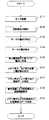
図1から図3は本発明の第1の実施の形態に係り、図1は回転自走式内視鏡装置の構成を示す図、図2は先端部及び挿入部先端側の構成を示す挿入軸方向に沿った部分断面図、図3は挿入部の全体を示す斜視図である。Embodiments of the present invention will be described below with reference to the drawings.
(First embodiment)
1 to 3 relate to a first embodiment of the present invention, FIG. 1 is a diagram showing a configuration of a rotating self-propelled endoscope device, and FIG. 2 is an insertion showing a configuration of a distal end portion and an insertion portion distal end side. FIG. 3 is a perspective view showing the entire insertion portion.
図1に示すように、回転自走式内視鏡装置1は、体腔内に挿入される細長の挿入部2と、この挿入部2の基端側に設けられた回動力発生手段である回動駆動部3及び操作部4と、この操作部4から延出されるユニバーサルコード5と、このユニバーサルコード5の先端側に設けられたユニバーサルコネクタ6と、このユニバーサルコネクタ6から延出される制御用ケーブル7と、この制御用ケーブル7が例えば着脱自在に接続される制御装置8と、この制御装置8に着脱自在に接続されるフットスイッチ9と、制御装置8と着脱自在に接続される報知手段である表示装置10と、を備えている。 As shown in FIG. 1, the rotary self-
挿入部2は、先端部11と、この先端部11の基端側に連設される推進力発生手段である回転筒体12を有して構成されている。この先端部11を備えた挿入部2の構成について、図2を参照して、より詳細に説明する。 The
図2に示すように、先端部11の先端面には、対物光学系21が配設されており、この対物光学系21の結像面に例えばCCD、CMOS等で構成される撮像手段である撮像素子22が配設されている。さらに、先端部11の先端面には、対物光学系21及び撮像素子22による撮影の対象となる被検体を照明するための照明用光源たるLED23が設けられている。撮像素子22から延出される信号線22aと、LED23から延出される電力線たる信号線23aとは、途中で一本にまとめられて、信号ケーブル26として基端側へ延長されている。 As shown in FIG. 2, an objective
また、先端部11の先端面には、対物光学系21を洗浄するための送水を行ったり、該対物光学系21に付着した水滴等を払拭する送気を行ったりするための送気送水ノズル24aが配設されている。この送気送水ノズル24aは、流体系管路である送気送水チューブ24に接続されていて、該送気送水チューブ24は基端側へ延長されている。 Further, an air / water supply nozzle for supplying water for cleaning the objective
さらに、先端部11の先端面には、例えば吸引等に用いられる流体系管路であるチャンネル25の開口25aが露呈しており、このチャンネル25は、基端側へ延長されている。 Further, an opening 25a of a
また、先端部11の基端側には、回転筒体12の先端側を突き当てるための硬質な部材、例えば、金属製の推進力受け部である突当部11aが設けられている。すなわち、後述するように、突当部11aに推進力が発生した回転筒体12の先端部分が当接することで、先端部11を含めた挿入部2全体が体腔の深部方向へ前進する。 Further, on the proximal end side of the
回転筒体12は、本実施の形態において、金属素線を螺旋状に巻回し、その外周面に螺旋状凸部(あるいは、螺旋状凹部、さらにあるいは、螺旋に沿って連設されるように突設される凸部、など)となる螺旋形状部が形成された部材である。詳しくは、回転筒体12は、体腔内への挿通性を考慮した螺旋管であり、例えばステンレス製で所定の径寸法の金属素線を螺旋状に1層に巻回して所定の可撓性を有するように形成したものである。また、金属素線は、1層に限ることなく、多条(例えば2条、3条、4条など)に巻いても良い。 In the present embodiment, the rotating
この金属素線を螺旋状に巻いていくときに、金属素線間の密着度を高めることができたり、螺旋の角度を種々設定できたりする。尚、本実施の形態においては、金属素線を巻回して外周面に螺旋状の凹凸となる螺旋形状部が形成された回転筒体12を例に挙げたが、例えば、可撓性を有するチューブの外表面に螺旋溝を形成した螺旋形状部を有する回転筒体にしても良い。 When the metal strands are wound in a spiral shape, the degree of adhesion between the metal strands can be increased, and various angles of the spiral can be set. In the present embodiment, the rotating
この回転筒体12は、挿入方向の軸周りに回動可能となるように構成されている。そして、この回転筒体12が回転すると、外周面の螺旋形状部が被検体の体腔内壁と接触して推力が発生し、該回転筒体12自体が挿入方向へ進行しようとする。このとき、回転筒体12の先端部が、前記突当部11aに当接して先端部11を押圧し、先端部11を含めた挿入部2全体が体腔内の深部に向かって前進する推進力が付与される。また、この回転筒体12は、図3に示すように、基端部分が複数の係合凸部16aが形成された係止手段である前口金16に接続されている。 The
回転筒体12の内周面側には、チューブ27が配設されている。このチューブ27は、上述したような送気送水チューブ24、チャンネル25、及び信号ケーブル26が内部に挿通されて保護するようになっているとともに、その外周面側において回転筒体12の回転を妨げることがないようになっている。また、チューブ27は、先端部分が突当部11aの基端と連結されており、基端部分に硬質な固定部である固定管17が連結されている。 A
チューブ27は、長手方向の長さが回転筒体12よりも長く、基端に連結された固定管17から送気送水チューブ24、チャンネル25、及び信号ケーブル26が延出している。これら挿入部2内に挿通されている送気送水チューブ24、チャンネル25及び信号ケーブル26は、回動駆動部3内を挿通された後に、再びこの回動駆動部3(図1参照)から外部に延出される。 The
送気送水チューブ24の端部には送気送水接続部24bが、チャンネル25の端部には吸引接続部25bが、信号ケーブル26の端部には信号接続部26bが、それぞれ設けられていて、これらは、操作部4の側面に設けられた接続部31(図1参照)に対して接続されるようになっている。 An air /
再び、図1の説明に戻って、挿入部2は、回動駆動部3に設けられた回動伝達手段である回動伝達部14に接続されるようになっていて、この接続により、回動駆動部3内に設けられている後述するモータの駆動力が回転筒体12に伝達されて、該回転筒体12の回転が行われるようになっている。尚、回動伝達部14は、後述するように、前抜け止め部材13との螺合により、挿入部2が着脱自在となっている。 Returning to the description of FIG. 1 again, the
操作部4には、手で把持するための把持部4aが設けられており、さらに、送気送水チューブ24を介しての送気や送水を操作するための送気送水ボタン4bや、チャンネル25を介しての吸引を操作するための吸引ボタン4cなどの、各種の操作ボタンが設けられている。 The operation unit 4 is provided with a grip portion 4a for gripping by hand, and further, an air /
操作部4から延出されるユニバーサルコード5内には、送気送水チューブ24に接続される送気送水管路や、チャンネル25に接続される吸引管路、あるいは信号ケーブル26に接続される信号線などが配設されている。 In the
ユニバーサルコード5の先端側に設けられたユニバーサルコネクタ6は、送気装置への接続部や、送水タンクへの接続部、吸引ポンプへの接続部、撮像素子22からの画像信号を処理するためのビデオプロセッサへの接続部などを備えている。
このユニバーサルコネクタ6から延出される制御用ケーブル7内には、回動駆動部3への信号線と、先端部11内に配設されているLED23への信号線と、が配設されている。The universal connector 6 provided on the distal end side of the
In the
制御用ケーブル7が接続される制御装置8は、回動駆動部3内に配設されているモータを制御したり、あるいはLED23の発光状態を制御したりするためのものであり、電源スイッチや各種のボリュームダイアル等が設けられたものとなっている。 The
フットスイッチ9は、回動駆動部3のモータを制御するためのものである。ただし、このフットスイッチ9を、LED23の発光状態を制御するのにも用い得るようにしても構わない。
また、表示装置10は、回転筒体12の回転速度、及び回転軸回りの負荷であるトルク(以下、単に回転トルクという)と、後述する駆動手段であるモータの駆動電流値を数値化して表示するための表示手段である。The
In addition, the
なお、上述したような構成において、挿入部2以外の部分、つまり、回動駆動部3、操作部4、ユニバーサルコード5、ユニバーサルコネクタ6、制御用ケーブル7、制御装置8、及びフットスイッチ9は、流体供給装置を構成するものである。さらに、流体供給装置としては、送気装置、送水タンク、吸引ポンプなどを含んでも良いし、加えてビデオプロセッサを含んでも構わない。従って、この回転自走式内視鏡装置1は、流体供給装置の少なくとも一部と、挿入部2と、を含んで構成されている。
また、回動駆動部3の下面には、該回動駆動部3を載置する際に用いる脚部15が複数設けられている。In the configuration as described above, portions other than the
In addition, a plurality of
次に、図4を用いて、着脱自在となっている挿入部2の基端部分が挿通している状態の回動駆動部3の内部構成について、詳しく説明する。尚、図4は、回動駆動部3の内部を示す断面図である。 Next, the internal configuration of the
図4に示すように、回動駆動部3は、外装を形成するケース3aを有している。このケース3aには、挿入部2が挿通できるように、前後(挿入部2が延出する方向を前方とする。)に2つの孔部が設けられている。 As shown in FIG. 4, the
このケース3aの前方側の孔部には、中途に外向フランジが形成された略円筒状の前ホルダ33が配設されている。この前ホルダ33は、外向フランジがケース3aの前方側の孔部近傍の内面と当接するまで前記孔部に挿通され、ケース3aから前方側へ突出した部分が前ホルダ止めリング35との螺合により、ケース3aに固定されている。 In the hole on the front side of the
また、ケース3aの後方側の孔部には、一端に外向フランジが形成された略円筒状の後ホルダ34が配設されている。この後ホルダ34は、外向フランジがケース3aの後方側の孔部近傍の内面と当接するまで前記孔部に挿通され、ケース3aから後方へ突出した部分が後ホルダ止めリング36との螺合により、ケース3aに固定されている。 A substantially cylindrical rear holder 34 having an outward flange formed at one end is disposed in the hole on the rear side of the
これら各ホルダ33,34には、ケース3aの各孔部の内周面と当接する箇所に1つ、及びその近傍の内周面に2つの合計3つの周溝が形成されており、各周溝に防水用のOリング33a,34aが配設されている。 Each of the
これら各ホルダ33,34内には、各ホルダ33,34を掛け渡すように回転パイプ37が挿通されている。この回転パイプ37は、前ホルダ33を固定しているフレーム38に設けられる2つのベアリング39によって回動保持され、前ホルダ33の開口部から前方へ突出している。 A rotating
回転パイプ37の基端側の中途(ベアリング39と後ホルダ34の間)には、固定螺子41aによってパイプ側プーリ41が固設されている。このパイプ側プーリ41は、フレーム38に設けられた減速機45aを備えたモータ45のモータ側プーリ46の回転によりプーリベルト42を介して回動される。これにより、パイプ側プーリ41が固設された回転パイプ37は、パイプ側プーリ41の回動に伴って回動される。 A pipe-
また、減速機45aは、モータ側プーリ46とパイプ側プーリ41の直径の違いにより、モータ45によるモータ側プーリ46の回転速度がプーリベルト42を介して所望の回転速度でパイプ側プーリ41を回転伝達させるためのものである。
尚、回動駆動部3のケース3a内は、回転パイプ37の回転時でも、上述した各ホルダ33,34の内周面に配設された各Oリング33a,34aにより、外部からの水密が保持されている。Further, the
In addition, the inside of the
この回転パイプ37内には、後端に連結手段である後口金48が連結された固定パイプ47が挿通している。後口金48には、中心軸に挿入部2のチューブ27と連結されている固定管17を挿通する孔が形成されている。また、後口金48には、後ホルダ34に形成された空間を形成する2つの切り欠き34bに係入される突出部となる複数の螺子50(図4では1つのみ表示している)が外周方向から螺着されている。 A fixed pipe 47 having a
螺子50には、中心軸にビス51を挿通する孔が形成されている。このビス51は、後口金48と螺着すると共に、後口金48に挿通する固定管17を端面で押圧固定している。また、後ホルダ34の後端部分には、切り欠き34bの切り口を覆うように、略円環状の後抜け防止部材49が螺着されている。 The
従って、体腔内の各屈曲部を通過する挿入部2において、後口金48、固定管17及びチューブ27は、上述のような構成とすることで、軸回りの回転が規制されると共に、軸方向の前後の移動が容易に可能となる。すなわち、後口金48に螺着される螺子50は、後ホルダ34の切り欠き34bと後抜け防止部材49によって形成された空間内で軸方向と直交する方向(回動駆動部3の前後を結んだ軸方向、つまり挿入部2の挿入軸方向)回りの回転が規制されると共に、回動駆動部3の前後に遊動可能となる。 Therefore, in the
このような構成とすることで、チューブ27は、回転筒体12の回動に追従することなく軸回りの回転が規制される。その結果、チューブ27内部に挿通する送気送水チューブ24、チャンネル25及び信号ケーブル26は、捩れによる損傷が防止される。 With such a configuration, the
また、送気送水チューブ24、チャンネル25及び信号ケーブル26には、例えば、挿入部2の湾曲状態に応じて、チューブ27が回転筒体12に対して、挿入軸方向の前後に動いた際に起こる牽引弛緩などの無理な負荷の発生が防止される。 Further, the air /
回転パイプ37は、前方側へ突出している部分に回動伝達部14が複数の螺子14b(図4では1つのみ図示)により固着されている。これにより、回動伝達部14は、回転パイプ37と共に回転する。この回動伝達部14には、前方側の端部から軸方向に沿った複数の被係合手段である係合溝14a(図4では1つのみ図示)が形成されている。 In the
回動伝達部14には、挿入部2の前口金16が係合され、前抜け止め部材13が螺着することで挿入部が接続される。このとき、前口金16に形成された係合手段である係合凸部16aは、回動伝達部14の係合溝14aと係合する。これにより、回転パイプ37の回転力は、回動伝達部14を介して、挿入部2に確実に伝達される。 The
詳しくは、前口金16の係合凸部16aは、その軸方向に対する側面が回動伝達部14の係合溝14aの軸方向に対する側面と当接する。そのため、前口金16は、回動伝達部14に対する軸方向の回動が規制される。
従って、回動伝達部14の回転力は、確実に前口金16に伝達される。その結果、前口金16に形成された係合凸部16aが回動駆動部3の回動伝達部14の係合溝14aと係合することで、回転パイプ37からの回転力が回動伝達部14を介して回転筒体12に確実に伝達される構成となっている。Specifically, the engaging
Therefore, the rotational force of the
また、回転が規制されている固定パイプ47は、その先端部分が回動伝達部14まで前方側へ突出しており、その先端面に摺動リング47aが配設されている。この摺動リング47aは、固定パイプ47の先端面が回転する前口金16の基端面との当接による摩擦抵抗を軽減するための部材である。 Further, the fixed pipe 47 whose rotation is restricted has a tip portion protruding forward to the
次に、図5、及び図6を用いて、本実施の形態の回転筒体12の挙動をモータの回転状態により検出し、表示装置10にその状態を告知するための電気的回路構成について説明する。尚、図5は、回転自走式内視鏡装置1の電気的回路構成を示すブロック図、図6は図5の電気回路構成により回転筒体12の回転速度、及び回転トルクを検出し、その動作一例を示すフローチャートである。 Next, an electrical circuit configuration for detecting the behavior of the
図5に示すように、制御装置8に接続される外部機器としての表示装置10は、回転駆動部3内に設けられ、モータ45の物理情報を検出する検出手段である抵抗素子52と図1に示した、操作部4、及びユニバーサルコード5を介して電気的に接続される。この抵抗素子52は、モータ45、及び電流計53と電気的に直列接続されており、この抵抗素子52、モータ45、及び電流計53には電源54からの駆動電流が供給されるようになっている。
抵抗素子52は、モータ45の電流を電圧に変換し、この変換した電圧を表示装置10に出力する抵抗であり、例えばカーボン抵抗などである。尚、本実施の形態では、モータ45の物理情報は、電流による回転速度を検出する抵抗素子52を用いているが、モータ45の異常を検出するため、モータ45の温度を検出する温度センサ、振動を検出する振動センサ、異音を検出する音検出センサなどを用いても良い。As shown in FIG. 5, the
The
図6のフローチャートを用いて、以上のように構成された回転自走式内視鏡装置1における、モータ45の回転トルク、並びに被検体の体腔内へ挿入された挿入部2の回転筒体12の回転速度、及び回転トルクを検出する一例について、各ステップ(S)に基づいた動作を説明する。 6, in the rotary self-propelled
先ず、術者(ユーザ)は、患者の体腔内、例えば、大腸内検査の場合、肛門から回転自走式内視鏡装置1の挿入部2を挿入する。そして、術者は、フットスイッチ9を踏み込んでスイッチON状態にして、回転筒体12を回転させる。 First, an operator (user) inserts the
このとき、モータ45が駆動し(S1)、減速機45aにより所定の回転速度、及び回転トルクでモータ側プーリ46が回転する。そして、モータ側プーリ46の回動により、プーリベルト42を介して、パイプ側プーリ41に回転が伝達され、回転筒体12が回転パイプ37、回動伝達部14、及び前口金16を介して、回転筒体12が所定の回転速度、回転トルクで回転する(S2)。 At this time, the
そして、上述したように、回転筒体12が回転すると、外周面の螺旋形状部が被検体の腸壁と接触して推力が発生し、該回転筒体12自体が挿入方向へ進行しようとする。このとき、回転筒体12の先端部が、前記突当部11aに当接して先端部11を押圧し、先端部11を含めた挿入部2全体が大腸内の深部に向かって前進する推進力が付与される。 Then, as described above, when the
また、挿入部2の大腸への挿入量に伴って、回転筒体12には、腸壁との摩擦抵抗が加わり、回転速度が低下し、所定の推進力を維持するための回転トルクが必要となる。このとき、モータ45には、その回転トルクを維持するために負荷がかかり、モータ45の電流値が変化する(S3)。電流計53は、挿入部2の大腸内への挿入時に、常に、モータ45の電流値を検出している(S4)。すなわち、モータ45の回転トルクが低下すると、モータ45を駆動する電流値が低下する。 Further, as the insertion amount of the
抵抗素子52は、モータ45の変化する電流に基づいて、電圧変換を行い(S5)、その電圧値を表示装置10に出力する(S6)。そして、表示装置10は、抵抗素子52から入力された検出電圧値に基づいて、回転筒体12の物理情報である回転速度、及び回転トルクを数値化して、表示部に表示する(S7)。 The
これにより、術者は、表示装置10に表示されている回転筒体12の回転速度、及び回転トルクによって、屈曲する大腸内での挿入部2の挿入状態を容易に把握することができる。すなわち、術者は、予め設定された回転筒体12が腸壁との接触で推進作用する最適な所定の範囲の回転速度、及び所定の範囲の回転トルクが表示装置10に表示されていれば、挿入部2が問題なく推進しながら挿入されていることが把握できる。 Thereby, the surgeon can easily grasp the insertion state of the
例えば、回転筒体12の所定の範囲の回転速度、或いは回転トルクが低下、或いは回転トルクが増加した場合、挿入部2が大腸内で充分な推進力が発生していなかったり、或いは挿入部2が大腸内で過剰なトルクを受けたり、回転駆動部3内のモータ45に異常が発生していなかったりするなどの不具合が生じていると考えられる。そのため、術者は、フットスイッチ9の踏み込みを開放してスイッチOFF状態にして、一旦、回転筒体12の回転を停止する。その後、術者は、挿入部2を捻り操作などの手元操作、或いは大腸からの抜去などを行い、再度、回転筒体12を回動させ、挿入部2の大腸への挿入を試みることができる。 For example, when the rotational speed or rotational torque within a predetermined range of the
以上の結果、本実施の形態の回転自走式内視鏡装置1によれば、体腔内に挿入される挿入部2の挿入状態を把握するために、推進力を発生させる回転筒体12の物理情報(回転速度、回転トルクなど)をリアルタイムで表示装置10から取得できるため、挿入部2の挿入時における異常を容易に察知することができる。 As a result of the above, according to the rotary self-propelled
尚、上述の回転筒体12が腸壁との接触で推進作用する最適な所定の範囲の回転速度、及び所定の範囲の回転トルクが、規定した範囲外の値となった際に、警報する警報手段としてのブザー、警告ランプなどを表示装置10に設けてもよく、また、操作部4に警報手段としてのバイブレーション機能を付加しても良い。 It should be noted that an alarm is issued when the rotation speed within the optimum predetermined range and the rotation torque within the predetermined range at which the above-described
(第2の実施の形態)
次に、本発明の第2の実施の形態に係る回転自走式内視鏡装置について図7、及び図8を用いて説明する。本実施の形態の説明において、上述の第1の実施の形態の回転自走式内視鏡装置1と同じ構成には、同じ符号を使って、その詳細な説明は省略する。尚、図7は、本実施の形態に係る回転自走式内視鏡装置1の電気的回路構成を示すブロック図、図8は図7の電気回路構成により回転筒体12の回転速度、及び回転トルクを検出し、メモリ素子に検出されたデータを格納する動作一例を示すフローチャートである。(Second Embodiment)
Next, a rotary self-propelled endoscope apparatus according to a second embodiment of the present invention will be described with reference to FIGS. In the description of the present embodiment, the same reference numerals are used for the same components as those of the rotary self-propelled
本実施形態の回転自走式内視鏡装置1は、図7に示すように、抵抗素子52にモータ45の回転速度、及び回転トルクを記憶する記憶媒体であるメモリ素子55が電気的に接続されている。このメモリ素子55は、電源54から電力が供給されている。 In the rotary self-propelled
図8のフローチャートを用いて、以上のように構成された本実施の形態の回転自走式内視鏡装置1における、被検体の体腔内(大腸内)へ挿入された挿入部2の回転筒体12の物理情報である回転速度、及び回転トルクを検出し、メモリ素子55により検出されたデータを格納する一例について、各ステップ(S)に基づいた動作を説明する。尚、本実施形態での図8に示すステップS11〜ステップS15は、第1の実施の形態で図6を用いて記載したステップS1〜ステップS5と同じ動作のため、その詳細説明を省略する。 Using the flowchart of FIG. 8, in the rotary self-propelled
本実施の形態の回転自走式内視鏡装置1では、図8に示すように、ステップ15で抵抗素子52により電圧変換された電圧値がメモリ素子55を介して表示装置10に出力される(S16)。このとき、メモリ素子55は、その電圧値の情報データを格納する(S17)。 In the rotary self-propelled
そして、メモリ素子55を介して電圧値が入力された表示装置10は、検出電圧値に基づいて、回転筒体12の物理情報である回転速度、及び回転トルクを数値化して、表示部に表示する(S18)と共に、メモリ素子55に回転筒体12の物理情報を出力する。 Then, the
メモリ素子55は、入力された回転筒体12の物理情報のデータを格納する(S19)。 The
以上のように、本実施の形態の回転自走式内視鏡装置1は、第1の実施の形態の効果に加え、メモリ素子55を備えることで、モータ45の電圧値、及び回転筒体12の動作履歴である物理情報を格納することができることで、この各種情報を基に故障時の修復などのデータとして、活用することができる構成となる。 As described above, the rotary self-propelled
(第3の実施の形態)
次に、本発明の第3の実施の形態に係る回転自走式内視鏡装置について図9、及び図10を用いて説明する。本実施の形態の説明において、上述の各実施の形態の回転自走式内視鏡装置1と同じ構成には、同じ符号を使って、その詳細な説明は省略する。尚、図9は、本実施の形態に係る回転自走式内視鏡装置1の電気的回路構成を示すブロック図、図10は図9の電気回路構成により回転筒体12の回転速度、及び回転トルクを検出し、制御回路による制御動作の一例を示すフローチャートである。(Third embodiment)
Next, a rotary self-propelled endoscope apparatus according to a third embodiment of the present invention will be described with reference to FIGS. In the description of the present embodiment, the same reference numerals are used for the same components as those of the rotary self-propelled
本実施の形態の回転自走式内視鏡装置1には、図9に示すように、モータ45、抵抗素子52、及び電流計53と直列で電気的に接続される制御回路56が設けられている。この制御回路56は、図9には図示していないが、回転駆動部3内に配設され、電源54とも電気的に接続されている。電源54からの駆動電流は、制御回路56を介して、モータ45、抵抗素子52、及び電流計53に供給される。 As shown in FIG. 9, the rotary self-propelled
図10のフローチャートを用いて、以上のように構成された本実施の形態の回転自走式内視鏡装置1における、被検体の体腔内(大腸内)へ挿入された挿入部2の回転筒体12の物理情報である回転速度、及び回転トルクを検出する制御の一例について説明する。尚、本実施形態での図10に示すステップS21〜ステップS25は、第1の実施の形態で図6を用いて記載したステップS1〜ステップS5と、図10に示す図ステップS26〜S29は第2の実施の形態で図8を用いて記載したステップS16〜S19と同じ動作のため、その詳細説明を省略する。 Using the flowchart of FIG. 10, in the rotary self-propelled
本実施の形態の回転自走式内視鏡装置1では、電流計53に接続された制御回路56がモータ45に供給される電流値をモニターしており、図10に示すように、ステップS30において、その電流値が所定の範囲の閾値外、ここでは異常な電流値となっているか否かの判断を制御回路56によって行われている(S30)。 In the rotary self-propelled
このステップS30において、制御回路56の判断のもと、モータ45に供給される電流値が所定の範囲の閾値内であった場合、再度、ステップS24に戻り、電流値が所定の範囲の閾値外となっていた場合、制御回路56はモータ45への電流供給を停止し、モータ45の駆動を停止する(S31)尚、ステップS30における、制御回路56が行う判断は、回転筒体12の適切な所定の範囲の回転速度、及び回転トルクの所定の閾値を設定し、モータ45に供給される電流値から導き出された回転速度、及び回転トルクから前記所定の範囲の閾値と比較して判断しても良い。 In step S30, if the current value supplied to the
以上のように、本実施の形態の回転自走式内視鏡装置1は、第2の実施の形態の効果に加え、制御回路56を設けることで、回転筒体12を駆動するモータ45の異常や、回転筒体12の適切な所定の回転速度、及び回転トルクの範囲外となった場合、異常と判断して自動的にモータ45の駆動を停止し、回転筒体12の回動を停止させることができる。 As described above, the rotary self-propelled
また、制御回路56は、図11に示すフローチャートに基づく制御を行うようにしても良い。図11は図9の電気回路構成により回転筒体12の回転速度、及び回転トルクを検出し、制御回路による制御動作の変形例を示すフローチャートである。尚、図11に示すステップS41〜ステップS49は、図10を用いて記載したステップS21〜ステップS29と同じ動作のため、その詳細説明を省略する。 Further, the
ステップS49でメモリ素子55に回転筒体12の物理情報のデータを格納した後、制御回路56は、電流計53によって検出された電流値に基づいて、モータ45の誘起電圧E変換を行う(S50)。そして、制御回路56は、予め設定されたモータ45における所定の基準誘起電圧Eαと、ステップS50で変換した誘起電圧Eとが同じ電圧値(E=Eα)であるか否かの判断を行う(S51)
制御回路56がモータ45の前記基準誘起電圧Eαと前記誘起電圧Eとが同じ電圧値(E=Eα)と判断した場合、ステップS44に移行し、大腸への挿入部2の挿入過程において、ステップS44〜S51の各ルーチンがループされる。一方で、制御回路56がモータ45の前記基準誘起電圧Eαと前記誘起電圧Eとが異なる電圧値(E>Eα、E<Eα)と判断した場合、制御回路56は、モータ45の誘起電圧Eをコントロール、すなわち、モータ45の前記基準誘起電圧Eαと前記誘起電圧Eとが同じ電圧値(E=Eα)となるように、モータ45への供給電圧を変更する(S52)。After storing the physical information data of the
When the
次に、電流計53によって、モータ45の電流値を検出し(S53)、その電流値が所定の範囲の閾値外、ここでは異常な電流値となっているか否かの判断を制御回路56によって行われる(S54)。 Next, the current value of the
このステップS54において、制御回路56の判断のもと、モータ45に供給される電流値が所定の範囲の閾値内であった場合、再度、ステップS45に戻り、電流値が所定の範囲の閾値外となっていた場合、制御回路56はモータ45への電流供給を停止し、モータ45の駆動を停止する(S55)
以上のように、本変形例の回転自走式内視鏡装置1は、上述の各効果に加え、回転筒体12を駆動するモータ45の回転速度、及び回転トルクを一定に保つことができるため、回転筒体12が予め設定された所定の回転速度、及び回転トルクが一定に保たれた状態で腸壁に作用するため、屈曲する大腸内への挿入部2の挿入性が向上する。In this step S54, if the current value supplied to the
As described above, the rotary self-propelled
(第4の実施の形態)
次に、本発明の第4の実施の形態に係る回転自走式内視鏡装置について図12を用いて説明する。本実施の形態の説明において、上述の各実施の形態の回転自走式内視鏡装置1と同じ構成には、同じ符号を使って、その詳細な説明は省略する。尚、図12は、本実施の形態に係る回転自走式内視鏡装置1の電気的回路構成を示し、パイプ側プーリ41の一面に配されたトルク検出用マグネットを説明するためのブロック図である。(Fourth embodiment)
Next, a rotary self-propelled endoscope apparatus according to a fourth embodiment of the present invention will be described with reference to FIG. In the description of the present embodiment, the same reference numerals are used for the same components as those of the rotary self-propelled
本実施の形態の回転自走式内視鏡装置1は、図12に示すように、パイプ側プーリ41の一面、ここでは基端面に複数のS極と複数のN極の磁性体を円周方向に互い違いに並べて配設したトルク検出用マグネット58と、パイプ側プーリ41の前記基端面近傍に配置され、トルク検出用マグネット58の磁気を検知する検出手段である磁気検知部57とを有している。 As shown in FIG. 12, the rotary self-propelled
磁気検知部57は、制御回路56と電気的に接続され、検出したトルク検出用マグネット58のS極、或いはN極の磁気を制御回路56に出力する。すなわち、磁気検知部57は、パイプ側プーリ41の回転により、トルク検出用マグネット58のS極、或いはN極が通過することによって、パイプ側プーリ41の物理情報である回転速度、及び回転トルクを検出し、その検出結果を制御回路56へ出力する。 The
その結果、磁気検知部57は、パイプ側プーリ41の回転速度、及び回転トルクが伝達される回転筒体12の物理情報(回転速度、及び回転トルク)を検出することができる。これにより、磁気検知部57により検出された値は、第3の実施の形態にて記述したメモリ素子55が格納する回転筒体12の物理情報データ、及び表示装置10により表示する回転筒体12の物理情報とすることができる。さらに、制御回路56は、磁気検知部57により検出された値をもとに、設定された回転筒体12の所定の範囲の回転速度、及び回転トルクと比較して判断することができる。 As a result, the
また、上述した各実施の形態における抵抗素子52をポテンショメータに変えて、回転筒体12の物理情報データの閾値を可変することができるよな構成にしても良い。 Further, the
尚、本発明は上述した実施形態に限定されるものではなく、発明の主旨を逸脱しない範囲内において種々の変形や応用が可能であることは勿論である。 It should be noted that the present invention is not limited to the above-described embodiment, and various modifications and applications can be made without departing from the spirit of the invention.
Claims (6)
Translated fromJapanese該挿入部の外周の長手軸回りに回転可能に設けられる推進力発生部と、
該推進力発生部を回転させる駆動手段を有する回動力発生手段と、
該回転発生手段の前記駆動手段の電流変化を検出する検出手段と、
該検出手段が検出した前記電流変化に基づいて、前記駆動手段を駆動制御して、前記推進力発生部の前記長手軸回りの回転速度および回転トルクを制御する制御部と、
を具備し、
前記制御部は、前記駆動手段であるモータの電流値に基づいて変換された該モータの誘起電圧が基準誘起電圧と同じ電圧値となるように供給電圧を変更して、前記推進力発生部の前記長手軸回りの回転速度および回転トルクが一定となるように制御することを特徴とする回転自走式内視鏡装置。An insertion section for insertion into a subject;
A propulsive force generator provided rotatably around the longitudinal axis of the outer periphery of the insertion part;
Rotation power generating means having driving means for rotating the propulsive force generating section;
Detecting means for detecting a current change in the driving means of the rotation generating means;
A control unit that drives and controls the driving unit based on the current change detected by the detection unit to control a rotational speed and a rotational torque of the propulsive force generating unit around the longitudinal axis;
Comprising
The control unit changes the supply voltage so that the induced voltage of the motor converted based on the current value of the motor as the driving unit becomes the same voltage value as the reference induced voltage, and the propulsive force generating unit A rotary self-propelled endoscope apparatus, wherein the rotational speed and rotational torque about the longitudinal axis are controlled to be constant.
Applications Claiming Priority (1)
| Application Number | Priority Date | Filing Date | Title |
|---|---|---|---|
| PCT/JP2005/018175WO2007043118A1 (en) | 2005-09-30 | 2005-09-30 | Rotary self-propelled endoscope device |
Publications (2)
| Publication Number | Publication Date |
|---|---|
| JPWO2007043118A1 JPWO2007043118A1 (en) | 2009-04-16 |
| JP4864003B2true JP4864003B2 (en) | 2012-01-25 |
Family
ID=37942388
Family Applications (1)
| Application Number | Title | Priority Date | Filing Date |
|---|---|---|---|
| JP2007539741AExpired - Fee RelatedJP4864003B2 (en) | 2005-09-30 | 2005-09-30 | Rotating self-propelled endoscope device |
Country Status (3)
| Country | Link |
|---|---|
| US (1) | US20090156897A1 (en) |
| JP (1) | JP4864003B2 (en) |
| WO (1) | WO2007043118A1 (en) |
Families Citing this family (16)
| Publication number | Priority date | Publication date | Assignee | Title |
|---|---|---|---|---|
| US7736300B2 (en) | 2003-04-14 | 2010-06-15 | Softscope Medical Technologies, Inc. | Self-propellable apparatus and method |
| US8317678B2 (en) | 2005-05-04 | 2012-11-27 | Olympus Endo Technology America Inc. | Rotate-to-advance catheterization system |
| US8235942B2 (en) | 2005-05-04 | 2012-08-07 | Olympus Endo Technology America Inc. | Rotate-to-advance catheterization system |
| US8574220B2 (en) | 2006-02-28 | 2013-11-05 | Olympus Endo Technology America Inc. | Rotate-to-advance catheterization system |
| JP4994771B2 (en)* | 2006-10-06 | 2012-08-08 | オリンパスメディカルシステムズ株式会社 | Rotating self-propelled endoscope system |
| JP5025319B2 (en)* | 2007-05-01 | 2012-09-12 | オリンパスメディカルシステムズ株式会社 | Rotating self-propelled endoscope system |
| US8870755B2 (en) | 2007-05-18 | 2014-10-28 | Olympus Endo Technology America Inc. | Rotate-to-advance catheterization system |
| US8333689B2 (en) | 2008-05-13 | 2012-12-18 | Olympus Medical Systems Corp. | Medical operation device |
| CN102497802A (en) | 2009-09-17 | 2012-06-13 | 富士胶片株式会社 | Propellable device with active size change capability |
| US20130172679A1 (en)* | 2011-07-01 | 2013-07-04 | Fujifilm Corporation | Endoscope insertion assisting device |
| JP5959388B2 (en)* | 2012-09-25 | 2016-08-02 | オリンパス株式会社 | In vivo introduction device |
| JP6322095B2 (en)* | 2014-09-08 | 2018-05-09 | オリンパス株式会社 | Insertion device |
| EP3216381A4 (en)* | 2014-12-25 | 2018-08-01 | Olympus Corporation | Insertion device |
| JP6840851B2 (en)* | 2017-07-12 | 2021-03-10 | オリンパス株式会社 | Control device, self-propelled endoscope system and control method |
| US11647896B2 (en)* | 2019-03-28 | 2023-05-16 | Olympus Corporation | Rollerless tubular connector for transferring rotative force from insertion section of endoscope to spiral tube |
| CN118510438A (en)* | 2021-11-05 | 2024-08-16 | 微诺弗斯公司 | Medical devices with remote control |
Citations (14)
| Publication number | Priority date | Publication date | Assignee | Title |
|---|---|---|---|---|
| JPS5542657A (en)* | 1978-09-22 | 1980-03-26 | Medos Kenkyusho Kk | Coelom inside induction device in endoscope* etc* |
| JPS58190902A (en)* | 1982-05-01 | 1983-11-08 | Sumitomo Electric Ind Ltd | image fiber scope |
| JPH0392126A (en)* | 1989-09-05 | 1991-04-17 | Olympus Optical Co Ltd | Apparatus for inserting endoscope |
| JPH04357925A (en)* | 1991-08-07 | 1992-12-10 | Olympus Optical Co Ltd | Endoscope device |
| JPH05211993A (en)* | 1992-02-07 | 1993-08-24 | Olympus Optical Co Ltd | Endoscopic device |
| JPH09285176A (en)* | 1996-04-11 | 1997-10-31 | Shimadzu Corp | DC brushless motor drive |
| JP2000107123A (en)* | 1998-10-05 | 2000-04-18 | Olympus Optical Co Ltd | Endoscope inserting device |
| JP2001317447A (en)* | 2000-05-09 | 2001-11-16 | Tokimec Inc | Hydraulic device |
| JP2002029432A (en)* | 2000-07-17 | 2002-01-29 | Mitsubishi Electric Corp | Electric power steering control device |
| JP2002034283A (en)* | 2000-07-18 | 2002-01-31 | Unisia Jecs Corp | Electric motor temperature estimation device |
| JP2003093327A (en)* | 2001-09-25 | 2003-04-02 | Pentax Corp | Endoscope device |
| JP2003285484A (en)* | 2002-03-28 | 2003-10-07 | Canon Inc | Paper thickness detecting means and image forming apparatus having the same |
| JP2005253892A (en)* | 2004-03-15 | 2005-09-22 | Olympus Corp | Internal propelling device for endoscope |
| WO2005089630A1 (en)* | 2004-03-18 | 2005-09-29 | Olympus Corporation | Insertion device |
Family Cites Families (8)
| Publication number | Priority date | Publication date | Assignee | Title |
|---|---|---|---|---|
| US5159446A (en)* | 1991-06-21 | 1992-10-27 | Olympus Optical Co., Ltd. | Electronic endoscope system provided with a separate camera controlling unit and motor controlling unit |
| US6159207A (en)* | 1997-07-31 | 2000-12-12 | Yoon; Inbae | Protected ablation method and apparatus |
| IL123646A (en)* | 1998-03-11 | 2010-05-31 | Refael Beyar | Remote control catheterization |
| US7344546B2 (en)* | 2000-04-05 | 2008-03-18 | Pathway Medical Technologies | Intralumenal material removal using a cutting device for differential cutting |
| US20010055748A1 (en)* | 2000-05-15 | 2001-12-27 | Bailey Bradford E. | System for training persons to perform minimally invasive surgical procedures |
| JP4744026B2 (en)* | 2001-07-30 | 2011-08-10 | オリンパス株式会社 | Capsule endoscope and capsule endoscope system |
| JP4503930B2 (en)* | 2003-01-30 | 2010-07-14 | オリンパス株式会社 | Medical equipment |
| WO2005113051A2 (en)* | 2004-05-14 | 2005-12-01 | Ethicon Endo-Surgery, Inc. | Medical instrument having a medical guidewire |
- 2005
- 2005-09-30JPJP2007539741Apatent/JP4864003B2/ennot_activeExpired - Fee Related
- 2005-09-30USUS12/066,330patent/US20090156897A1/ennot_activeAbandoned
- 2005-09-30WOPCT/JP2005/018175patent/WO2007043118A1/enactiveApplication Filing
Patent Citations (14)
| Publication number | Priority date | Publication date | Assignee | Title |
|---|---|---|---|---|
| JPS5542657A (en)* | 1978-09-22 | 1980-03-26 | Medos Kenkyusho Kk | Coelom inside induction device in endoscope* etc* |
| JPS58190902A (en)* | 1982-05-01 | 1983-11-08 | Sumitomo Electric Ind Ltd | image fiber scope |
| JPH0392126A (en)* | 1989-09-05 | 1991-04-17 | Olympus Optical Co Ltd | Apparatus for inserting endoscope |
| JPH04357925A (en)* | 1991-08-07 | 1992-12-10 | Olympus Optical Co Ltd | Endoscope device |
| JPH05211993A (en)* | 1992-02-07 | 1993-08-24 | Olympus Optical Co Ltd | Endoscopic device |
| JPH09285176A (en)* | 1996-04-11 | 1997-10-31 | Shimadzu Corp | DC brushless motor drive |
| JP2000107123A (en)* | 1998-10-05 | 2000-04-18 | Olympus Optical Co Ltd | Endoscope inserting device |
| JP2001317447A (en)* | 2000-05-09 | 2001-11-16 | Tokimec Inc | Hydraulic device |
| JP2002029432A (en)* | 2000-07-17 | 2002-01-29 | Mitsubishi Electric Corp | Electric power steering control device |
| JP2002034283A (en)* | 2000-07-18 | 2002-01-31 | Unisia Jecs Corp | Electric motor temperature estimation device |
| JP2003093327A (en)* | 2001-09-25 | 2003-04-02 | Pentax Corp | Endoscope device |
| JP2003285484A (en)* | 2002-03-28 | 2003-10-07 | Canon Inc | Paper thickness detecting means and image forming apparatus having the same |
| JP2005253892A (en)* | 2004-03-15 | 2005-09-22 | Olympus Corp | Internal propelling device for endoscope |
| WO2005089630A1 (en)* | 2004-03-18 | 2005-09-29 | Olympus Corporation | Insertion device |
Also Published As
| Publication number | Publication date |
|---|---|
| US20090156897A1 (en) | 2009-06-18 |
| WO2007043118A9 (en) | 2007-05-31 |
| JPWO2007043118A1 (en) | 2009-04-16 |
| WO2007043118A1 (en) | 2007-04-19 |
Similar Documents
| Publication | Publication Date | Title |
|---|---|---|
| JP4864003B2 (en) | Rotating self-propelled endoscope device | |
| JP4668643B2 (en) | Endoscope device | |
| US8876703B2 (en) | Rotary self-propelled endoscope | |
| US8177709B2 (en) | Rotary self-propelled endoscope system | |
| US20070244354A1 (en) | Vibratory Device, Endoscope Having Such A Device, Method For Configuring An Endoscope, And Method Of Reducing Looping Of An Endoscope. | |
| EP2158834A1 (en) | Endoscope system, imaging system, and image processing device | |
| JP5284570B2 (en) | Rotating self-propelled endoscope system | |
| US9271632B2 (en) | Rotation unit, insertion apparatus, insertion body, and insertion system | |
| EP2898816A1 (en) | Insertion aid, insertion body, and insertion device | |
| JP2007307241A (en) | Rotating self-propelled endoscope and rotating self-propelled endoscope apparatus | |
| JP2006334246A (en) | Endoscope apparatus | |
| JP4583809B2 (en) | Endoscope and endoscope apparatus | |
| JP4699472B2 (en) | Rotating self-propelled endoscope device | |
| JP4584997B2 (en) | Rotating self-propelled endoscope device | |
| JP4564531B2 (en) | Rotating self-propelled endoscope device | |
| JP4611552B2 (en) | Endoscopy vibrator | |
| JP4625076B2 (en) | Insertion part of insertion device | |
| JP4625088B2 (en) | Rotating self-propelled endoscope device | |
| JP2008194179A (en) | Rotating self-propelled endoscope system | |
| WO2007057962A1 (en) | Rotary self-propelled endoscope device | |
| JP2007185390A (en) | Rotating self-propelled endoscope system, program | |
| JP2008194080A (en) | Intracelom mover | |
| JP2002233497A (en) | Endoscope | |
| JP2005329001A (en) | Insertion assisting tool and endoscope apparatus |
Legal Events
| Date | Code | Title | Description |
|---|---|---|---|
| A131 | Notification of reasons for refusal | Free format text:JAPANESE INTERMEDIATE CODE: A131 Effective date:20110208 | |
| A521 | Request for written amendment filed | Free format text:JAPANESE INTERMEDIATE CODE: A523 Effective date:20110401 | |
| A131 | Notification of reasons for refusal | Free format text:JAPANESE INTERMEDIATE CODE: A131 Effective date:20110607 | |
| A521 | Request for written amendment filed | Free format text:JAPANESE INTERMEDIATE CODE: A523 Effective date:20110701 | |
| TRDD | Decision of grant or rejection written | ||
| A01 | Written decision to grant a patent or to grant a registration (utility model) | Free format text:JAPANESE INTERMEDIATE CODE: A01 Effective date:20111018 | |
| A01 | Written decision to grant a patent or to grant a registration (utility model) | Free format text:JAPANESE INTERMEDIATE CODE: A01 | |
| A61 | First payment of annual fees (during grant procedure) | Free format text:JAPANESE INTERMEDIATE CODE: A61 Effective date:20111108 | |
| FPAY | Renewal fee payment (event date is renewal date of database) | Free format text:PAYMENT UNTIL: 20141118 Year of fee payment:3 | |
| R151 | Written notification of patent or utility model registration | Ref document number:4864003 Country of ref document:JP Free format text:JAPANESE INTERMEDIATE CODE: R151 | |
| FPAY | Renewal fee payment (event date is renewal date of database) | Free format text:PAYMENT UNTIL: 20141118 Year of fee payment:3 | |
| S111 | Request for change of ownership or part of ownership | Free format text:JAPANESE INTERMEDIATE CODE: R313111 | |
| R350 | Written notification of registration of transfer | Free format text:JAPANESE INTERMEDIATE CODE: R350 | |
| S531 | Written request for registration of change of domicile | Free format text:JAPANESE INTERMEDIATE CODE: R313531 | |
| R350 | Written notification of registration of transfer | Free format text:JAPANESE INTERMEDIATE CODE: R350 | |
| R250 | Receipt of annual fees | Free format text:JAPANESE INTERMEDIATE CODE: R250 | |
| R250 | Receipt of annual fees | Free format text:JAPANESE INTERMEDIATE CODE: R250 | |
| R250 | Receipt of annual fees | Free format text:JAPANESE INTERMEDIATE CODE: R250 | |
| R250 | Receipt of annual fees | Free format text:JAPANESE INTERMEDIATE CODE: R250 | |
| LAPS | Cancellation because of no payment of annual fees |