JP4862774B2 - Driving support method and driving support device - Google Patents
Driving support method and driving support deviceDownload PDFInfo
- Publication number
- JP4862774B2 JP4862774B2JP2007205670AJP2007205670AJP4862774B2JP 4862774 B2JP4862774 B2JP 4862774B2JP 2007205670 AJP2007205670 AJP 2007205670AJP 2007205670 AJP2007205670 AJP 2007205670AJP 4862774 B2JP4862774 B2JP 4862774B2
- Authority
- JP
- Japan
- Prior art keywords
- pillar
- vehicle
- image
- virtual plane
- data
- Prior art date
- Legal status (The legal status is an assumption and is not a legal conclusion. Google has not performed a legal analysis and makes no representation as to the accuracy of the status listed.)
- Expired - Fee Related
Links
Images


Classifications
- B—PERFORMING OPERATIONS; TRANSPORTING
- B60—VEHICLES IN GENERAL
- B60R—VEHICLES, VEHICLE FITTINGS, OR VEHICLE PARTS, NOT OTHERWISE PROVIDED FOR
- B60R1/00—Optical viewing arrangements; Real-time viewing arrangements for drivers or passengers using optical image capturing systems, e.g. cameras or video systems specially adapted for use in or on vehicles
- B60R1/20—Real-time viewing arrangements for drivers or passengers using optical image capturing systems, e.g. cameras or video systems specially adapted for use in or on vehicles
- B60R1/22—Real-time viewing arrangements for drivers or passengers using optical image capturing systems, e.g. cameras or video systems specially adapted for use in or on vehicles for viewing an area outside the vehicle, e.g. the exterior of the vehicle
- B60R1/23—Real-time viewing arrangements for drivers or passengers using optical image capturing systems, e.g. cameras or video systems specially adapted for use in or on vehicles for viewing an area outside the vehicle, e.g. the exterior of the vehicle with a predetermined field of view
- B60R1/25—Real-time viewing arrangements for drivers or passengers using optical image capturing systems, e.g. cameras or video systems specially adapted for use in or on vehicles for viewing an area outside the vehicle, e.g. the exterior of the vehicle with a predetermined field of view to the sides of the vehicle
- G—PHYSICS
- G02—OPTICS
- G02B—OPTICAL ELEMENTS, SYSTEMS OR APPARATUS
- G02B27/00—Optical systems or apparatus not provided for by any of the groups G02B1/00 - G02B26/00, G02B30/00
- G02B27/01—Head-up displays
- G—PHYSICS
- G06—COMPUTING OR CALCULATING; COUNTING
- G06T—IMAGE DATA PROCESSING OR GENERATION, IN GENERAL
- G06T15/00—3D [Three Dimensional] image rendering
- G06T15/10—Geometric effects
- G06T15/20—Perspective computation
- G—PHYSICS
- G06—COMPUTING OR CALCULATING; COUNTING
- G06T—IMAGE DATA PROCESSING OR GENERATION, IN GENERAL
- G06T5/00—Image enhancement or restoration
- G06T5/80—Geometric correction
- H—ELECTRICITY
- H04—ELECTRIC COMMUNICATION TECHNIQUE
- H04N—PICTORIAL COMMUNICATION, e.g. TELEVISION
- H04N7/00—Television systems
- H04N7/18—Closed-circuit television [CCTV] systems, i.e. systems in which the video signal is not broadcast
- B—PERFORMING OPERATIONS; TRANSPORTING
- B60—VEHICLES IN GENERAL
- B60R—VEHICLES, VEHICLE FITTINGS, OR VEHICLE PARTS, NOT OTHERWISE PROVIDED FOR
- B60R11/00—Arrangements for holding or mounting articles, not otherwise provided for
- B60R2011/0001—Arrangements for holding or mounting articles, not otherwise provided for characterised by position
- B60R2011/0003—Arrangements for holding or mounting articles, not otherwise provided for characterised by position inside the vehicle
- B60R2011/0019—Side or rear panels
- B60R2011/0022—Pillars
- B—PERFORMING OPERATIONS; TRANSPORTING
- B60—VEHICLES IN GENERAL
- B60R—VEHICLES, VEHICLE FITTINGS, OR VEHICLE PARTS, NOT OTHERWISE PROVIDED FOR
- B60R2300/00—Details of viewing arrangements using cameras and displays, specially adapted for use in a vehicle
- B60R2300/20—Details of viewing arrangements using cameras and displays, specially adapted for use in a vehicle characterised by the type of display used
- B60R2300/202—Details of viewing arrangements using cameras and displays, specially adapted for use in a vehicle characterised by the type of display used displaying a blind spot scene on the vehicle part responsible for the blind spot
- B—PERFORMING OPERATIONS; TRANSPORTING
- B60—VEHICLES IN GENERAL
- B60R—VEHICLES, VEHICLE FITTINGS, OR VEHICLE PARTS, NOT OTHERWISE PROVIDED FOR
- B60R2300/00—Details of viewing arrangements using cameras and displays, specially adapted for use in a vehicle
- B60R2300/20—Details of viewing arrangements using cameras and displays, specially adapted for use in a vehicle characterised by the type of display used
- B60R2300/205—Details of viewing arrangements using cameras and displays, specially adapted for use in a vehicle characterised by the type of display used using a head-up display
- B—PERFORMING OPERATIONS; TRANSPORTING
- B60—VEHICLES IN GENERAL
- B60R—VEHICLES, VEHICLE FITTINGS, OR VEHICLE PARTS, NOT OTHERWISE PROVIDED FOR
- B60R2300/00—Details of viewing arrangements using cameras and displays, specially adapted for use in a vehicle
- B60R2300/30—Details of viewing arrangements using cameras and displays, specially adapted for use in a vehicle characterised by the type of image processing
- B60R2300/306—Details of viewing arrangements using cameras and displays, specially adapted for use in a vehicle characterised by the type of image processing using a re-scaling of images
- B—PERFORMING OPERATIONS; TRANSPORTING
- B60—VEHICLES IN GENERAL
- B60R—VEHICLES, VEHICLE FITTINGS, OR VEHICLE PARTS, NOT OTHERWISE PROVIDED FOR
- B60R2300/00—Details of viewing arrangements using cameras and displays, specially adapted for use in a vehicle
- B60R2300/60—Details of viewing arrangements using cameras and displays, specially adapted for use in a vehicle characterised by monitoring and displaying vehicle exterior scenes from a transformed perspective
- B60R2300/602—Details of viewing arrangements using cameras and displays, specially adapted for use in a vehicle characterised by monitoring and displaying vehicle exterior scenes from a transformed perspective with an adjustable viewpoint
- B—PERFORMING OPERATIONS; TRANSPORTING
- B60—VEHICLES IN GENERAL
- B60R—VEHICLES, VEHICLE FITTINGS, OR VEHICLE PARTS, NOT OTHERWISE PROVIDED FOR
- B60R2300/00—Details of viewing arrangements using cameras and displays, specially adapted for use in a vehicle
- B60R2300/80—Details of viewing arrangements using cameras and displays, specially adapted for use in a vehicle characterised by the intended use of the viewing arrangement
- B60R2300/802—Details of viewing arrangements using cameras and displays, specially adapted for use in a vehicle characterised by the intended use of the viewing arrangement for monitoring and displaying vehicle exterior blind spot views
- B—PERFORMING OPERATIONS; TRANSPORTING
- B60—VEHICLES IN GENERAL
- B60R—VEHICLES, VEHICLE FITTINGS, OR VEHICLE PARTS, NOT OTHERWISE PROVIDED FOR
- B60R2300/00—Details of viewing arrangements using cameras and displays, specially adapted for use in a vehicle
- B60R2300/80—Details of viewing arrangements using cameras and displays, specially adapted for use in a vehicle characterised by the intended use of the viewing arrangement
- B60R2300/8033—Details of viewing arrangements using cameras and displays, specially adapted for use in a vehicle characterised by the intended use of the viewing arrangement for pedestrian protection
- G—PHYSICS
- G02—OPTICS
- G02B—OPTICAL ELEMENTS, SYSTEMS OR APPARATUS
- G02B27/00—Optical systems or apparatus not provided for by any of the groups G02B1/00 - G02B26/00, G02B30/00
- G02B27/01—Head-up displays
- G02B27/0101—Head-up displays characterised by optical features
- G02B2027/0138—Head-up displays characterised by optical features comprising image capture systems, e.g. camera
- G—PHYSICS
- G02—OPTICS
- G02B—OPTICAL ELEMENTS, SYSTEMS OR APPARATUS
- G02B27/00—Optical systems or apparatus not provided for by any of the groups G02B1/00 - G02B26/00, G02B30/00
- G02B27/01—Head-up displays
- G02B27/0101—Head-up displays characterised by optical features
- G02B2027/014—Head-up displays characterised by optical features comprising information/image processing systems
Landscapes
- Engineering & Computer Science (AREA)
- Physics & Mathematics (AREA)
- Theoretical Computer Science (AREA)
- General Physics & Mathematics (AREA)
- Multimedia (AREA)
- Computing Systems (AREA)
- Geometry (AREA)
- Computer Graphics (AREA)
- Optics & Photonics (AREA)
- Signal Processing (AREA)
- Mechanical Engineering (AREA)
- Traffic Control Systems (AREA)
- Closed-Circuit Television Systems (AREA)
- Navigation (AREA)
- Fittings On The Vehicle Exterior For Carrying Loads, And Devices For Holding Or Mounting Articles (AREA)
- Image Processing (AREA)
Description
Translated fromJapanese本発明は、運転支援方法及び運転支援装置に関する。 The present invention relates to a driving support method and a driving support device.
従来より、安全運転を支援する装置として、ドライバーの死角となる領域を車載カメラによって撮影し、ディスプレイ等に表示する車載システムが開発されている。その一つとして、車両のフロントピラーによって生じる死角領域を車載カメラで撮影し、撮影画像をフロントピラーの内側に表示するシステムが提案されている。フロントピラーは、フロントウィンドウやルーフを支える左右の支柱であって、運転席に着座したドライバーからみて斜め前方に位置し、ドライバーの視界を一部遮ってしまうものの、安全性のために所定の太さを確保しなければならない部材である。 2. Description of the Related Art Conventionally, as an apparatus that supports safe driving, an in-vehicle system that captures an area that is a blind spot of a driver with an in-vehicle camera and displays it on a display or the like has been developed. As one of such systems, a system has been proposed in which a blind spot area caused by a front pillar of a vehicle is photographed with an in-vehicle camera and a photographed image is displayed inside the front pillar. The front pillar is a left and right column that supports the front window and roof.It is located diagonally forward when viewed from the driver seated in the driver's seat and partially blocks the driver's field of view. This is a member that must be secured.
上記したシステムは、図12に示すように、車体に取り付けられ、撮影領域106を撮影可能なカメラ100と、カメラ100から出力された映像信号を画像処理する画像プロセッサと、フロントピラー101内側に画像を投影するプロジェクタ(図示略)等を備えている。これによれば、ドライバー位置102から見て、あたかもフロントピラー101を透過して外部の背景を視認できるような状態になるので、交差点等において、車両の前側方の道路形状や、前側方にある障害物を確認することができる。 As shown in FIG. 12, the system described above includes a
カメラ100によって撮影された映像信号をピラー101に投影する際、カメラ100の視角とドライバーの視角とが一致しないため、ピラー101に投影された画像が、ドライバがウィンドウを介して視認している背景に対して傾いたりずれたりする問題がある。これに対し、特許文献1では、カメラで撮影された画像を、ドライバーの視角に合わせるために設定された仮想平面(仮想スクリーン面)に投影変換している。
ところが、図12に示すようにドライバー位置102から一定距離の位置に仮想平面103を定義すると、その一定距離の位置以外にある道路標示、信号、障害物等は、ピラーに投影画像として投影された際に、適切に表示されないことがある。即ち、図12に模式的に示すように仮想平面103上に視認対象物104がある場合、この視認対象物104は図13に示すようにピラー101に画像104aとして投影されても歪むことがない。仮想平面103以外の位置にある視認対象物105は、ピラー101に画像105aとして表示されると、ウィンドウ107,108を介して見える実際の背景に対してずれたり、歪んだりした状態で表示されてしまう。 However, when the
このため、例えば道路標示や歩行者といった、ドライバーが注視しやすい障害物が仮想平面103上にない場合には、それらの障害物が歪んだ状態でピラーに投影されるので、ドライバーが違和感を感じることがある。 For this reason, when there are no obstacles on the
本発明は、上記問題点に鑑みてなされたものであり、その目的は、特定の対象物の画像を良好にピラーに投影することができる運転支援方法及び運転支援装置を提供することにある。 The present invention has been made in view of the above problems, and an object of the present invention is to provide a driving support method and a driving support device that can satisfactorily project an image of a specific object on a pillar.
上記問題点を解決するために、請求項1に記載の発明は、車両に取り付けられた撮影装置を用いて、前記車両のピラーによって生じる死角領域を撮影し、前記撮影装置によって撮影された画像を前記ピラーの内側に表示する運転支援方法であって、車両周辺の路面上の物体を描画基準物として設定し、ドライバーの頭部中心位置と前記描画基準物とを結んだ直線に基づいて該描画基準物を通る位置に仮想平面を設定するとともに、前記撮影装置から入力した画像データを前記仮想平面に座標変換し、座標変換された前記画像データに基づき、前記ピラーの内側に、前記ピラーによって生じる死角領域に相当する画像を表示することを要旨とする。In order to solve the above-described problems, the invention according to
請求項2に記載の発明は、車両に取り付けられた撮影装置を用いて、前記車両のピラーによって生じる死角領域を撮影し、前記撮影装置によって撮影された画像を前記ピラーの内側に表示する運転支援装置において、車両周辺の路面上の物体を描画基準物として設定する対象物設定手段と、ドライバーの頭部中心位置と前記描画基準物とを結んだ直線に基づいて該描画基準物を通る位置に仮想平面を設定する仮想平面設定手段と、前記撮影装置から入力した画像データを前記仮想平面上に座標変換する画像処理手段と、前記仮想平面上に座標変換された前記画像データに基づき、前記ピラーの内側に、前記ピラーによって生じる死角領域に相当する画像を表示する出力制御手段とを備えたことを要旨とする。According to a second aspect of the present invention, driving assistance for photographing a blind spot region caused by a pillar of the vehicle using an imaging device attached to the vehicle and displaying an image captured by the imaging device inside the pillar. in the device, and the object setting means for setting an object on a road surface around the vehicle as a drawing reference object, the position passing throughthe drawing reference objecton the basis of a straight line connecting the head center position of the driver and said drawing reference object Based on the virtual plane setting means for setting a virtual plane, the image processing means for converting the image data input from the imaging device onto the virtual plane, and the pillar based on the image data converted on the virtual plane. And an output control means for displaying an image corresponding to a blind spot area generated by the pillar.
請求項3に記載の発明は、請求項2に記載の運転支援装置において、前記対象物設定手段は、路面標示又は路面設置物の位置を記憶した地図データに基づき、前記路面標示又は路面設置物を前記描画基準物として設定することを要旨とする。 The invention according to
請求項4に記載の発明は、請求項2に記載の運転支援装置において、路面上に存在する障害物を検出する障害物検出手段をさらに備え、前記対象物設定手段は、前記障害物を前記描画基準物として設定することを要旨とする。 The invention described in
請求項5に記載の発明は、請求項2〜4のいずれか1項に記載の運転支援装置において、前記撮影装置の撮影面を、前記仮想平面と交差する位置に設定することを要旨とする。 The invention according to
請求項1に記載の発明によれば、描画基準物を通る位置に仮想平面を設定し、その仮想平面に画像データを座標変換するので、車両が移動しても、描画基準物を常に歪みのない状態でピラー内面に表示することができる。 According to the first aspect of the present invention, since the virtual plane is set at a position passing through the drawing reference object, and the image data is coordinate-converted to the virtual plane, the drawing reference object is always distorted even if the vehicle moves. It is possible to display on the inner surface of the pillar in a state without any.
請求項2に記載の発明によれば、運転支援装置は、描画基準物を通る位置に仮想平面を設定し、その仮想平面に画像データを座標変換するので、車両が移動しても、描画基準物の画像を常に歪みのない状態でピラー内面に表示することができる。 According to the second aspect of the present invention, the driving support apparatus sets a virtual plane at a position passing through the drawing reference object, and coordinate-converts the image data to the virtual plane. An image of an object can always be displayed on the inner surface of the pillar without distortion.
請求項3に記載の発明によれば、路面標示又は路面設置物を描画基準物として設定するので、路面標示又は路面設置物の画像を歪みのない状態でピラーに表示することができる。また、地図データに基づき予め描画基準物の位置が取得できるため、座標変換を行うタイミングが遅くならず、描画基準物に接近した際に、その描画基準物を歪みなく表示できる。 According to the invention described in
請求項4に記載の発明によれば、路面上に存在する障害物を描画基準物として設定するので、ドライバーが注視する必要のある歩行者等を歪ませることなく表示することができる。 According to the fourth aspect of the present invention, since the obstacle existing on the road surface is set as the drawing reference object, a pedestrian or the like that the driver needs to watch can be displayed without distorting.
請求項5に記載の発明によれば、撮影装置の撮影面は仮想平面と交差する位置に設定されるので、撮影装置はその仮想平面上の物体、即ち描画基準物にピントを合わせて撮影することができる。このため、描画基準物をピラー内面に明瞭に表示できる。 According to the fifth aspect of the present invention, since the photographing surface of the photographing apparatus is set at a position intersecting with the virtual plane, the photographing apparatus performs photographing while focusing on an object on the virtual plane, that is, a drawing reference object. be able to. For this reason, the drawing reference object can be clearly displayed on the inner surface of the pillar.
以下、本発明を具体化した一実施形態を図1〜図10に従って説明する。図1は、自動車に実装された運転支援システム1の構成を説明するブロック図である。
運転支援システム1は車両C(図3参照)に搭載され、図1に示すように、運転支援装置としての運転支援ユニット2、ディスプレイ3、投影装置としてのプロジェクタ4、スピーカ5、撮像装置としてのカメラ6、第1〜第3位置検出センサ8a〜8cを備えている。Hereinafter, an embodiment embodying the present invention will be described with reference to FIGS. FIG. 1 is a block diagram illustrating a configuration of a
The
運転支援ユニット2は、制御部10、不揮発性のメインメモリ11、ROM12、GPS受信部13を備えている。制御部10は、CPU、MPU又はASIC等であって、ROM12に格納された運転支援プログラムに従って、各処理の主制御を行う。メインメモリ11は、制御部10の演算結果を一時記憶する。 The
制御部10は、GPS衛星からGPS受信部13が受信した、衛星軌道情報及び時刻情報を取得して、電波航法により自車両の絶対位置を算出する。また、制御部10は、運転支援ユニット2の車両側I/F部14を介して、車両Cに設けられた車速センサ30及びジャイロ31から車速パルス、角速度をそれぞれ入力する。そして、制御部10は、車速パルス及び角速度を用いる自律航法により、基準位置からの相対位置を算出し、電波航法で算出した絶対位置と組み合わせて自車位置を特定する。 The
また、運転支援ユニット2は、地理データ記憶部15を備えている。地理データ記憶部15は、内蔵ハードディスク、又は光ディスク等の外部記憶媒体である。この地理データ記憶部15には、目的地までの経路を探索するための地図データとしての各経路ネットワークデータ(以下、経路データ16という)と、ディスプレイ3に地図画面3aを出力するための地図データとしての各地図描画データ17とが記憶されている。 The
経路データ16は、全国を区画したメッシュ内の道路に関するデータである。経路データ16は、各メッシュの識別子、交差点及び道路の端点を示すノードに関するノードデータ、各ノードを接続する各リンクの識別子、リンクコスト等のデータを有している。制御部10は、この経路データ16を用いて、目的地までの推奨経路を探索したり、車両Cが交差点等の案内地点に接近しているか否かを判断する。 The route data 16 is data relating to roads in the mesh dividing the whole country. The route data 16 includes data such as identifiers of each mesh, node data related to nodes indicating intersections and road endpoints, identifiers of links connecting the nodes, and link costs. The
また、地図描画データ17は、道路形状、背景等を描画するためのデータであって、全国の地図を分割したメッシュ毎に格納されている。この地図描画データ17には、中央線、路側帯を区画する白線、ゼブラゾーン、横断歩道等の道路標示と、信号機等の路面設置物とに関するデータが格納されている。具体的には道路標示の種類、道路標示の位置座標、路面設置物の種類、路面設置物の位置座標等が、各地点の交差点やカーブと関連付けられて記憶されている。 The map drawing data 17 is data for drawing a road shape, a background, and the like, and is stored for each mesh obtained by dividing a map of the whole country. The map drawing data 17 stores data on road markings such as a center line, a white line that divides a roadside zone, a zebra zone, and a pedestrian crossing, and road surface installations such as traffic lights. Specifically, the types of road markings, the position coordinates of road markings, the types of road surface installation objects, the position coordinates of road surface installation objects, and the like are stored in association with the intersections and curves of each point.
図1に示すように、運転支援ユニット2は、地図描画プロセッサ18を備えている。地図描画プロセッサ18は、自車位置周辺の地図を描画するための地図描画データ17を地理データ記憶部15から読出して、地図出力用のデータを生成し、地図出力用データに基づく地図画面3aをディスプレイ3に表示する。また、地図描画プロセッサ18は、この地図画面3aに、自車位置を示す自車位置指標3bを重畳する。 As shown in FIG. 1, the driving
また、運転支援ユニット2は、音声プロセッサ24を備えている。音声プロセッサ24は、図示しない音声ファイルを有し、例えば目的地までの経路を案内する音声をスピーカ5から出力する。さらに、運転支援ユニット2は、外部入力I/F部25を備えている。外部入力I/F部25は、ディスプレイ3に隣接された操作スイッチ26、タッチパネル式のディスプレイ3から、ユーザの入力操作に基づいた入力信号を入力し、制御部10に
出力する。In addition, the driving
また、運転支援ユニット2は、検出手段を構成するセンサI/F部23を備えている。センサI/F部23は、第1〜第3位置検出センサ8a〜8cから、検出信号を入力する。第1〜第3位置検出センサ8a〜8cは、超音波センサから構成され、図2に示すように、車室内であって、フロントシートFに着座したドライバーDの周囲に取り付けられている。第1位置検出センサ8aは、ルームミラー(図示略)近傍に取り付けられ、ドライバーDの頭部D1とほぼ同じ高さか、若干高い位置に位置している。 The driving
第2位置検出センサ8bは、ドアウィンドウW2(図3参照)の上端付近に、ドライバーDの斜め前方右側に位置するように取り付けられている。第3位置検出センサ8cは、フロントシートFの左側であって、ルーフRの内側に取り付けられている。各位置検出センサ8a〜8cの図示しないセンサヘッドから発信された超音波は、ドライバーDの頭部D1に反射する。各位置検出センサ8a〜8cは、超音波を発信してから反射波を受信するまでの時間を計測し、その計測時間に基づいて、頭部D1までの各相対距離をそれぞれ算出する。算出された各相対距離は、センサI/F部23を介して制御部10に出力される。尚、各位置検出センサ8a〜8cからの信号に基づいて、センサI/F部23が頭部D1までの相対距離を算出するようにしてもよい。 The second
制御部10は、運転席に着座した状態で、標準的な体型のドライバーDの頭部D1が移動し得る頭部移動範囲と、第1〜第3位置検出センサ8a〜8cが検出した各相対距離とに基づき、頭部中心位置Dcを三角測量等を用いて、公知の方法で取得する。 The
また、図1に示すように、運転支援ユニット2は、映像データ入力部22と、この映像データ入力部22から画像データIMを入力する、対象物設定手段、仮想平面設定手段、画像処理手段及び出力制御手段としての画像プロセッサ20を備えている。映像データ入力部22は、制御部10の制御に基づいて、車両Cに設けられたカメラ6を駆動して、カメラ6によって撮影された画像データIMを入力する。 As shown in FIG. 1, the driving
カメラ6は、カラー画像を撮像するカメラであって、レンズ、ミラー等から構成される光学機構と、CCD撮像素子(いずれも図示せず)、自動焦点機構等を備えている。図3に示すように、このカメラ6は、車両CのフロントピラーP(以下、単にピラーPという)の外側に、光軸を車両Cの前方に向けて取り付けられている。本実施形態では、車両右側に配置された運転席に合わせ、カメラ6は、運転席側の右側のピラーPに取り付けられる。このカメラ6は、車両Cの前方右側と、車両Cの右側の一部を含む撮影領域Z1の背景を撮像する。 The
運転支援ユニット2の画像プロセッサ20は、映像データ入力部22を介して、カメラ6から画像データIMを取得する。また、画像プロセッサ20は、取得した画像データIMのうち、ピラーPによって遮られた領域をトリミングするとともに、画像の歪みを解消するための画像処理を行う。画像処理されたデータは、車室内に設けられたプロジェクタ4(図7参照)に出力され、プロジェクタ4はピラーPによって遮られた画像をピラーPの内側に投影する。 The
詳述すると、制御部10が、経路データ16に基づいて車両Cが交差点やカーブに接近したと判断すると、画像プロセッサ20は、交差点やカーブでドライバーDが注視しやすい視認対象物の座標を取得する。本実施形態では、画像プロセッサ20は、地図描画データ17に基づいて、描画基準物としての横断歩道Zの座標を取得する。例えば、図4に示すように、地図描画データ17に基づき、車両前側方に標示された横断歩道Zの基準点Pcの座標を取得する。基準点Pcは、予め地図描画データ17に記憶されているか、若し
くは地図描画データ17に記憶された横断歩道Z全体の座標から画像プロセッサ20が設定する。More specifically, when the
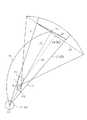
基準点Pcの座標を取得すると、基準点Pcの座標と、第1〜第3位置検出センサ8a〜8cが検出したドライバーDの頭部中心位置Dcとに基づいて、仮想平面VPの位置を決定する。仮想平面VPは、基準点Pcが設定された横断歩道Zの歪みを補正するための平面であって、ドライバーDの視点を原点とし、ドライバーDの視角に合わせて設定した仮想面である。この仮想平面VP上にある物体は、カメラ6によって撮影された画像データIMを仮想平面VP上に座標変換した際に、ずれたり傾いたりすることなく表示される性質がある。図5に示すように、画像プロセッサ20は、この仮想平面VPを、基準点Pcを含み、頭部中心位置Dcと基準点Pcとを結んだ直線Laに対して垂直になる位置に設定する。 When the coordinates of the reference point Pc are acquired, the position of the virtual plane VP is determined based on the coordinates of the reference point Pc and the head center position Dc of the driver D detected by the first to third
図4に示すように、車両Cが、仮想平面VPを設定した初期位置FPから、図中2点鎖線で示す位置に移動し、頭部中心位置Dcと横断歩道Zの基準点Pcとの相対距離ΔLが変化しても、画像プロセッサ20は、基準点Pcを通り、且つ直線Laに対して垂直となる位置に仮想平面VPを設定する。即ち、仮想平面VPは、車両Cの前進に伴って移動させずに、常に基準点Pcを通る位置に設定する。図4に示すように、車両が旋回している場合、頭部中心位置Dcと基準点Pcとを結ぶ直線Laの傾きが変わるので、その変化に伴い、仮想平面VPもその角度のみを変更する。 As shown in FIG. 4, the vehicle C moves from the initial position FP where the virtual plane VP is set to a position indicated by a two-dot chain line in the figure, and the relative position between the head center position Dc and the reference point Pc of the pedestrian crossing Z. Even if the distance ΔL changes, the
また、画像プロセッサ20は、仮想平面VPの位置に応じてカメラ撮影面CPを決定する。図5に示すように、カメラ撮影面CPは、カメラ6の光軸AXに対して垂直な面である。画像プロセッサ20は、このカメラ撮影面CPを、仮想平面VPと交差する位置に設定する。仮想平面VPと交差する面が複数設定可能な場合には、基準点Pc付近で交差する面を選択する。 Further, the
カメラ撮影面CPを設定すると、画像プロセッサ20は、映像データ入力部22を介して、カメラ撮影面CP上にカメラ6のピントを合わせて撮影し、画像データIMを取得する。 When the camera photographing plane CP is set, the
画像データIMを取得すると、その画像データIMのうち、ピラーPによって遮られる死角部分をトリミングする。図5に示すように、画像プロセッサ20は、ドライバーDの頭部中心位置DcとピラーPの各端点P1,P2を通る接線L1,L2を算出し、これらの接線L1,L2の内側を死角領域Aとする。また、画像データIMのうち、死角領域Aに相当する領域をトリミングして、ピラー死角データBDを生成する。 When the image data IM is acquired, a blind spot portion that is blocked by the pillar P in the image data IM is trimmed. As shown in FIG. 5, the
ピラー死角データBDを取得すると、画像プロセッサ20は、ピラー死角データBDを、基準点Pcを通る仮想平面VPに投影変換する。この投影変換は、カメラ撮影面CPのうち、死角領域A内にある死角部分CBの各画素を、仮想平面VP上の各画素に座標変換する処理であって、公知の座標変換を用いることができる。 When the pillar blind spot data BD is acquired, the
さらに、画像プロセッサ20は、仮想平面VPに投影変換した画像を、ROM12に記憶されたピラー形状41(図1参照)に基づき、ピラーPの内側面Paを含むピラー面上に投影変換する。ピラー面は、ROM12に記憶されたピラー形状41(図1参照)の3次元座標に基づき設定することができる。ピラー形状41は、ピラーPの外形をパターン又は座標で示したデータであって、車種によって異なるデータである。画像プロセッサ20は、このピラー形状41に基づき、ピラーPの外形を示す長さ方向、車幅方向及び鉛直方向の3次元の座標を取得することができる。また、ピラーの幅や長さも、3次元の座標を用いたデータとして取得することができる。 Further, the
続いて、画像プロセッサ20は、ピラーPの3次元形状に合わせて変換された上記画像を車内に設けられたプロジェクタ4により投影するために、該画像をプロジェクタ4の位置に合わせて座標変換する。即ち、プロジェクタ4から出力された光がピラー内側面に入射する角度によって、ピラー内側面に表示される画像は、歪んだり、拡大又は縮小される。従って、例えば、投影変換した上記画像の各画素の座標と、プロジェクタ4に対して出力する画像の各画素の座標とを予め関連付けたマップ等をメインメモリ11等に予め格納しておき、該マップに基づき、投影変換した画像を、プロジェクタ4への出力画像としてさらに座標変換する。そして、座標変換した画像を、プロジェクタ4に対して出力するための投影データPDとする。 Subsequently, the
また、画像プロセッサ20は、投影データPDに対し、ROM12に記憶されたマスクパターン40(図1及び図6参照)に基づき、プロジェクタ4に出力するための映像信号を生成する。図6に示すように、マスクパターン40は、投影データPDにマスクをかけるためのデータであって、ピラーPの内面形状に沿った画像表示領域40aと、マスク40bとから構成されている。画像プロセッサ20は、画像表示領域40aの領域には、投影データPDを読み込み、マスク40bの領域は、プロジェクタ4の非表示にするための出力用データODを生成する。出力用データODを生成すると、画像プロセッサ20は、その出力用データODをプロジェクタ4に出力する。 Further, the
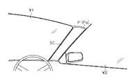
プロジェクタ4は、図7に示すように、ルーフRの内側であって、ドライバーDが着座するフロントシートFの鉛直方向上方付近に、車両Cの右側のピラーPの内面に画像を投影可能に取り付けられている。図8に示すように、ピラーPの内側面Paには、ピラーPの形状に合わせて切断されたスクリーンSCが貼着されている。プロジェクタ4の焦点は、このスクリーンSCに合わせて調整されている。尚、ピラーPの内側面Paがプロジェクタ4から出力された投影光を受光して鮮明な画像を表示できる材質及び形状からなる場合には、スクリーンSCは省略してもよい。 As shown in FIG. 7, the
図9に示すように、プロジェクタ4は、ピラーPのスクリーンSCに対して投影光Lを出射し、スクリーンSCに画像を投影する。また、そのスクリーンSCの周囲のフロントウィンドウW1又はドアウィンドウW2には、マスク40bにより画像が投影されないようになっている。 As shown in FIG. 9, the
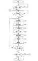
次に、本実施形態の処理手順について、図10に従って説明する。まず運転支援ユニット2の制御部10は、ピラーPの内側に背景画像を投影する投影モードの開始を待機する(ステップS1)。例えば、タッチパネル、操作スイッチ26が操作され、制御部10が外部入力I/F部25を介して、モード開始要求を受信した場合に、投影モードを開始すると判断する。或いは、イグニッションモジュール(図示略)からのオン信号に基づき、投影モードを開始すると判断してもよい。 Next, the processing procedure of this embodiment will be described with reference to FIG. First, the
投影モードを開始すると判断すると(ステップS1においてYES)、制御部10は、経路データ16に基づき、車両Cが交差点又はカーブに接近するのを待機する(ステップS2)。具体的には、制御部10は、車両Cの現在位置が、T字路を含む交差点又は所定の曲率以上のカーブから所定距離範囲(例えば200m)内に進入したと判断すると、交差点又はカーブに接近したと判断する。 If it is determined that the projection mode is to be started (YES in step S1), the
交差点又はカーブに接近したと判断すると(ステップS2においてYES)、制御部10は、各位置検出センサ8a〜8cを用いて、ドライバーDの頭部位置を検出する(ステップS3)。このとき、制御部10は、センサI/F部23を介して、各位置検出センサ8a〜8cから、頭部D1までの各相対距離を取得する。そして、各相対距離を用いて、
三角測量の原理とに基づき、頭部中心位置Dcを特定する。When it is determined that the vehicle has approached the intersection or curve (YES in step S2), the
Based on the principle of triangulation, the head center position Dc is specified.
頭部中心位置Dcを算出すると、画像プロセッサ20は、上記したように、仮想平面VPを設定する(ステップS4)。車両Cが交差点J(図4参照)に接近しているときは、横断歩道Zの基準点Pcを地図描画データ17に基づき取得して、その基準点Pcを通る位置に仮想平面VPを設定する。横断歩道Zが無い場合には、車両前方の停止線等の道路標示でもよい。車両Cがカーブに接近しているときは、道路に標示された中央線のうち、曲率が大きい位置に基準点Pcを取るようにしてもよい。 When the head center position Dc is calculated, the
さらに、画像プロセッサ20は、カメラ撮影面CPを設定する(ステップS5)。このとき、カメラ撮影面CP及び仮想平面VPの交点が、基準点Pc上に重なるか、若しくは基準点Pc付近を通るようにカメラ撮影面CPを設定する。カメラ撮影面CPと仮想平面VPが基準点Pc上に重ならない又はその交点が基準点Pc付近にならない場合には、少なくともカメラ撮影面CPが仮想平面VPと交差するように設定する。また、画像プロセッサ20の設定したカメラ撮影面CPに基づき、カメラ6は、ピントをカメラ撮影面CPに合わせて撮影を行い、画像データIMを取得する(ステップS6)。 Further, the
また、画像プロセッサ20は、上記したように、ピラーPによって遮られる死角領域Aを設定し、画像データIMのうち、その死角領域Aに相当する領域を抽出し(ステップS7)、ピラー死角データBDを生成する。 Further, as described above, the
ピラー死角データBDを生成すると、画像プロセッサ20は、ピラー死角データBDに対し画像処理を行う(ステップS8)。具体的には、上記したように、ピラー死角データBDを、ステップS4で設定した仮想平面VPに投影変換する。さらに、仮想平面VPに投影変換した画像を、ROM12に記憶されたピラー形状41に合わせて変換し、変換した該画像をプロジェクタ4により投影するために、プロジェクタ4の位置に合わせて座標変換して、投影データPDを生成する。また、投影データPD及びマスクパターン40に基づき、ピラーP以外の領域をマスクした出力用データODを生成する。 When the pillar blind spot data BD is generated, the
出力用データODを生成すると、画像プロセッサ20は、その出力用データODをプロジェクタ4に出力する。プロジェクタ4は、図9に示すように、ピラーPの内側面Paに設けられたスクリーンSCに、ピラーPによって遮られた領域の画像を投影する(ステップS9)。スクリーンSCに表示された投影画像は、予め横断歩道Z等の道路標示に合わせた仮想平面VPに投影変換されているので、その道路標示は、フロントウィンドウW1及びドアウィンドウW2を介して視認される背景と、ずれたり傾いたりすることなく表示される。このため、少なくとも交差点J又はカーブを通過する際に注視しがちな道路標示を歪むことなくピラーPに投影するので、ドライバーは違和感を感じることなく、ピラーPによって遮られた画像を視認することができる。 When the output data OD is generated, the
画像プロセッサ20によりピラーPに画像を投影すると、制御部10は、車両Cが、交差点J又はカーブから離れたか否かを判断する(ステップS10)。車両Cが、交差点J又はカーブ内又はその付近にあると判断すると(ステップS10においてNO)、ステップS3に戻り、頭部位置検出(ステップS3)から画像投影(ステップS9)までを繰り返す。即ち、車両Cが交差点J又はカーブを離れるまで、ピラーPによって遮られた画像がピラーPに投影される。 When the
車両Cが交差点J又はカーブから離れたと判断すると(ステップS10においてYES)、制御部10は、投影モードを終了するか否かを判断する(ステップS11)。終了トリガは、タッチパネルや操作スイッチ26の操作によるモード終了要求、又はイグニッションモジュールのオフ信号である。これらの信号を入力すると、投影モード終了であると
判断して(ステップS11においてYES)、処理を終了する。If it is determined that vehicle C has left the intersection J or the curve (YES in step S10),
上記実施形態によれば、以下のような効果を得ることができる。
(1)上記実施形態では、画像プロセッサ20は、車両Cが交差点又はカーブに接近した際に、仮想平面VPを、例えば道路標示といった対象物の基準点Pcを通る位置に常に設定するようにした。そして、その仮想平面VPにカメラ6が撮影した画像データIMを投影変換するようにした。従って、車両Cが移動しても、ドライバーが注視する対象物を常に歪みのない状態でピラーPの内側面Paに表示できるので、ドライバーに違和感を感じさせないようにすることができる。According to the above embodiment, the following effects can be obtained.
(1) In the above embodiment, when the vehicle C approaches an intersection or curve, the
(2)上記実施形態では、地理データ記憶部に記憶された地図描画データ17に基づき、道路標示等の対象物の座標を取得し、その対象物に基準点Pcを設定するようにした。このため、運転支援システム1が有する地図描画データ17を利用して予め基準点Pcを設定できるので、車両Cが交差点J又はカーブに進入開始する時点から、歪みのない画像をピラーPに表示できる。 (2) In the above embodiment, the coordinates of an object such as a road marking are acquired based on the map drawing data 17 stored in the geographic data storage unit, and the reference point Pc is set for the object. For this reason, since the reference point Pc can be set in advance using the map drawing data 17 of the driving
(3)上記実施形態では、画像プロセッサ20は、仮想平面VPと交差する位置にカメラ撮影面CPを設定するようにした。このため、仮想平面VP上の道路標示等の対象物にピントを合わせて撮影できるので、その道路標示をコントラストが高い状態で表示することができる。 (3) In the above embodiment, the
尚、上記実施形態は以下のように変更してもよい。
・上記実施形態では、地図描画データ17に基づき道路標示の基準点Pcを設定するようにしたが、カメラ6から取得した画像データIMに対して白線認識処理を行って、道路標示の白線(又は黄線)を検出するようにしてもよい。そして、検出した白線の端や中央に、基準点Pcを設定するようにしてもよい。In addition, you may change the said embodiment as follows.
In the above embodiment, the road marking reference point Pc is set based on the map drawing data 17. However, the white line recognition processing is performed on the image data IM acquired from the
・上記実施形態では、仮想平面VPを横断歩道Z等の道路標示に合わせるようにしたが、仮想平面VPの位置を合わせる対象物は適宜変更してもよい。例えば、信号機等の路面設置物に仮想平面VPを合わせるようにしてもよい。また例えば、車両Cに車両前方の障害物までの相対距離を計測する、障害物検出手段としてのレーダ等を搭載し、歩行者、自転車等の対象障害物が検出された場合に、仮想平面VPを障害物に合わせるようにしてもよい。尚、障害物が、例えば歩行者、自転車であるか否かの判定は、特徴検出等の公知の画像処理を用いる。 In the above embodiment, the virtual plane VP is adjusted to the road marking such as the pedestrian crossing Z, but the object to match the position of the virtual plane VP may be changed as appropriate. For example, the virtual plane VP may be matched with a road surface installation such as a traffic light. Further, for example, when a vehicle C is equipped with a radar or the like as an obstacle detection means for measuring a relative distance to an obstacle ahead of the vehicle, and a target obstacle such as a pedestrian or a bicycle is detected, the virtual plane VP You may make it match with an obstacle. For example, a known image process such as feature detection is used to determine whether the obstacle is a pedestrian or a bicycle.
・横断歩道等の路面標示の位置を示すデータは、例えば、路車間通信又は車車間通信、又はそれらのデータを配信するサーバから取得するようにしてもよい。また、歩行者等の障害物の位置を示すデータも、他車両等の外部装置から受信するようにしてもよい。 -The data which show the position of road markings, such as a pedestrian crossing, may be acquired from the server which distributes road-to-vehicle communication or vehicle-to-vehicle communication, or those data, for example. Data indicating the position of an obstacle such as a pedestrian may also be received from an external device such as another vehicle.
・上記実施形態では、音声案内を用いない場合には、音声プロセッサ24を省略しても良い。
・上記実施形態では、カメラ撮影面CPを、仮想平面VPに交差するように設定したが、図11に示すように、仮想平面VPの手前に設定するようにしてもよい。例えば、仮想平面VPのうちピラーPによって遮られる死角部分B1の端点B2,B3と、カメラ6の視点Vとによって囲まれる領域B内であって、仮想平面VPとカメラ6との間にカメラ撮影面CP2を設定するようにしても良い。この場合、画像データIMのうち、ピラーPによって遮られる領域Bに相当する部分を抽出する。そして、抽出したデータを、カメラ撮影面CP2から仮想平面VPに投影変換する。このようにしても、基準点Pcにある道路標示、歩行者等の視認対象物を歪ませることなくピラーPに表示することができる。In the above embodiment, the
In the above embodiment, the camera photographing plane CP is set so as to intersect the virtual plane VP. However, as shown in FIG. 11, it may be set before the virtual plane VP. For example, in the virtual plane VP, in the area B surrounded by the end points B2 and B3 of the blind spot portion B1 blocked by the pillar P and the viewpoint V of the
・上記実施形態では、プロジェクタ4によってピラーPの内側面Paに画像を投影するようにしたが、ピラーPの内側に薄型の表示手段としてのディスプレイを設け、画像プロセッサ20からそのディスプレイに出力用データODを出力しても良い。 In the above embodiment, the
・上記実施形態では、カメラ6はフロントピラーPの外側に設け、フロントピラーPによって遮られる領域を撮影するようにしたが、車両後方や側方等、その他のピラーに設けるようにしてもよい。例えば、カメラ6を車両後方のリヤピラー外側に取り付け、そのカメラ6によってリヤピラーにより遮られる領域を撮影するようにしてもよい。この場合、プロジェクタ4を、リヤピラー内面に画像を投影可能な位置に設け、画像プロセッサ20は、カメラ6によって撮影された画像データに基づき、リヤピラーによって遮られた死角領域の画像をリヤピラー内面に投影する。これにより、例えば車両Cが駐車枠に向かって後退する場合に、ドライバーがリヤピラーによって遮られた駐車枠を投影画像にて確認することができるので、駐車操作を行いやすくすることができる。また、複数のピラーPの外側に1つずつカメラ6を設けるとともに、プロジェクタ4をカメラ6の位置に応じて複数台設けるようにしてもよい。さらに、一つのピラーPに複数のカメラ6を設けるようにしてもよい。 In the above embodiment, the
・上記実施形態では、プロジェクタ4を車両CのルーフRの内側に設けるようにしたが、プロジェクタ4の位置はピラーPの内面に画像を投影できる位置であればよく、例えばダッシュボードの上方(略中央)等、その他の位置に設けるようにしてもよい。 In the above embodiment, the
1…運転支援システム、2…運転支援装置としての運転支援ユニット、4…投影装置としてのプロジェクタ、6…撮影装置としてのカメラ、16…地図データとしての経路データ、17…地図データとしての地図描画データ、20…対象物設定手段、仮想平面設定手段、画像処理手段及び出力制御手段としての画像プロセッサ、A…死角領域、B…死角領域としての死角部分、C…車両、CP…撮影面としてのカメラ撮影面、IM…画像データ、P…ピラー、Pc…描画基準物としての基準点、VP…仮想平面、Z…路面上の物体、描画基準物としての横断歩道。DESCRIPTION OF
Claims (5)
Translated fromJapanese車両周辺の路面上の物体を描画基準物として設定し、ドライバーの頭部中心位置と前記描画基準物とを結んだ直線に基づいて該描画基準物を通る位置に仮想平面を設定するとともに、前記撮影装置から入力した画像データを前記仮想平面に座標変換し、座標変換された前記画像データに基づき、前記ピラーの内側に、前記ピラーによって生じる死角領域に相当する画像を表示することを特徴とする運転支援方法。A driving support method for photographing a blind spot region caused by a pillar of the vehicle using a photographing device attached to a vehicle, and displaying an image photographed by the photographing device on the inside of the pillar,
An object on the road surface around the vehicle is set as adrawing reference object , a virtual plane is set at a position passing through the drawing reference objectbased on a straight line connecting the head center position of thedriver and the drawing reference object, and The image data input from the imaging device is coordinate-converted into the virtual plane, and an image corresponding to a blind spot area generated by the pillar is displayed inside the pillar based on the image data subjected to the coordinate conversion. Driving support method.
車両周辺の路面上の物体を描画基準物として設定する対象物設定手段と、
ドライバーの頭部中心位置と前記描画基準物とを結んだ直線に基づいて該描画基準物を通る位置に仮想平面を設定する仮想平面設定手段と、
前記撮影装置から入力した画像データを前記仮想平面上に座標変換する画像処理手段と、
前記仮想平面上に座標変換された前記画像データに基づき、前記ピラーの内側に、前記ピラーによって生じる死角領域に相当する画像を表示する出力制御手段と
を備えたことを特徴とする運転支援装置。In a driving assistance device that uses a photographing device attached to a vehicle to photograph a blind spot region caused by a pillar of the vehicle and displays an image photographed by the photographing device on the inside of the pillar.
Object setting means for setting an object on the road surface around the vehicle as a drawing reference object;
A virtual plane setting means for setting a virtual plane at a position that passes throughthe drawing reference objecton the basis of a straight line connecting the head center position of the driver and said drawing reference object,
Image processing means for coordinate-converting image data input from the imaging device on the virtual plane;
A driving support apparatus comprising: output control means for displaying an image corresponding to a blind spot area generated by the pillar on the inner side of the pillar based on the image data coordinate-transformed on the virtual plane.
前記対象物設定手段は、路面標示又は路面設置物の位置を記憶した地図データに基づき、前記路面標示又は路面設置物を前記描画基準物として設定することを特徴とする運転支援装置。In the driving assistance device according to claim 2,
The said object setting means sets the said road marking or road surface installation thing as the said drawing reference | standard object based on the map data which memorize | stored the position of the road marking or road surface installation object, The driving assistance apparatus characterized by the above-mentioned.
路面上に存在する障害物を検出する障害物検出手段をさらに備え、
前記対象物設定手段は、前記障害物を前記描画基準物として設定することを特徴とする運転支援装置。In the driving assistance device according to claim 2,
An obstacle detection means for detecting an obstacle present on the road surface;
The target object setting means sets the obstacle as the drawing reference object, and a driving support device according to claim 1.
前記撮影装置の撮影面を、前記仮想平面と交差する位置に設定することを特徴とする運転支援装置。In the driving assistance device according to any one of claims 2 to 4,
A driving support device, wherein a photographing surface of the photographing device is set at a position intersecting with the virtual plane.
Priority Applications (1)
| Application Number | Priority Date | Filing Date | Title |
|---|---|---|---|
| JP2007205670AJP4862774B2 (en) | 2006-12-20 | 2007-08-07 | Driving support method and driving support device |
Applications Claiming Priority (3)
| Application Number | Priority Date | Filing Date | Title |
|---|---|---|---|
| JP2006343348 | 2006-12-20 | ||
| JP2006343348 | 2006-12-20 | ||
| JP2007205670AJP4862774B2 (en) | 2006-12-20 | 2007-08-07 | Driving support method and driving support device |
Publications (2)
| Publication Number | Publication Date |
|---|---|
| JP2008174212A JP2008174212A (en) | 2008-07-31 |
| JP4862774B2true JP4862774B2 (en) | 2012-01-25 |
Family
ID=39272214
Family Applications (1)
| Application Number | Title | Priority Date | Filing Date |
|---|---|---|---|
| JP2007205670AExpired - Fee RelatedJP4862774B2 (en) | 2006-12-20 | 2007-08-07 | Driving support method and driving support device |
Country Status (5)
| Country | Link |
|---|---|
| US (1) | US8094192B2 (en) |
| EP (1) | EP1939040B1 (en) |
| JP (1) | JP4862774B2 (en) |
| CN (1) | CN101207802B (en) |
| AT (1) | ATE533667T1 (en) |
Families Citing this family (31)
| Publication number | Priority date | Publication date | Assignee | Title |
|---|---|---|---|---|
| EP2291836B1 (en) | 2008-05-21 | 2018-09-12 | ADC Automotive Distance Control Systems GmbH | Driver assistance system for preventing a vehicle colliding with pedestrians |
| DE102009006471A1 (en)* | 2009-01-28 | 2010-09-02 | Audi Ag | Method for operating a navigation device of a motor vehicle and motor vehicle therefor |
| WO2011093354A1 (en)* | 2010-01-29 | 2011-08-04 | 富士通テン株式会社 | Image processing device and image processing method |
| DE102010034853A1 (en)* | 2010-08-18 | 2012-02-23 | Gm Global Technology Operations Llc (N.D.Ges.D. Staates Delaware) | Motor vehicle with digital projectors |
| CN104081763B (en)* | 2012-01-17 | 2018-09-14 | 日本先锋公司 | Image processing apparatus, image processing server, image processing method, image processing program and recording medium |
| CN104584097B (en)* | 2012-08-09 | 2017-04-05 | 丰田自动车株式会社 | Article detection device and drive assistance device |
| CN103456167B (en)* | 2013-09-17 | 2015-08-26 | 重庆大学 | Based on the good driving technology parameter acquiring method of critical area |
| JP6032219B2 (en)* | 2014-01-24 | 2016-11-24 | トヨタ自動車株式会社 | Driving assistance device |
| GB2525653A (en)* | 2014-05-01 | 2015-11-04 | Jaguar Land Rover Ltd | Apparatus and method for providing information within a vehicle |
| WO2016018320A1 (en)* | 2014-07-30 | 2016-02-04 | Johnson Controls Technology Company | System for projecting an image within a vehicle interior |
| US9707960B2 (en) | 2014-07-31 | 2017-07-18 | Waymo Llc | Traffic signal response for autonomous vehicles |
| CN104504677B (en)* | 2014-11-17 | 2017-09-22 | 南京泓众电子科技有限公司 | A kind of image generating method based on variable visual angle |
| CN113147580A (en)* | 2015-04-10 | 2021-07-23 | 麦克赛尔株式会社 | Vehicle with image projection part |
| CN105405093B (en)* | 2015-11-12 | 2019-03-15 | 中国商用飞机有限责任公司 | Aircraft cockpit visual field enhancement system and method |
| JP6536521B2 (en)* | 2016-09-22 | 2019-07-03 | 株式会社デンソー | Object detection apparatus and object detection method |
| US10668857B2 (en)* | 2016-09-30 | 2020-06-02 | Sony Corporation | Reflector, information display apparatus, and movable body |
| WO2018129310A1 (en)* | 2017-01-08 | 2018-07-12 | Shanghai Yanfeng Jinqiao Automotive Trim Systems Co. Ltd | System and method for image display on vehicle interior component |
| JP6897222B2 (en)* | 2017-03-27 | 2021-06-30 | トヨタ自動車株式会社 | Front pillar structure |
| KR102347689B1 (en)* | 2017-04-10 | 2022-01-05 | 현대자동차주식회사 | Apparatus for Displaying the Blind Spot of the Vehicle |
| CN107392093B (en)* | 2017-06-14 | 2019-01-01 | 北京遥感设备研究所 | A kind of rail identifying system combined based on machine learning and gray projection algorithm |
| DE102017216822A1 (en)* | 2017-09-22 | 2019-03-28 | Continental Automotive Gmbh | An apparatus and method for adjusting image processing based on a shape of a display device for a motor vehicle |
| CN114127822B (en)* | 2019-07-12 | 2024-05-10 | 日产自动车株式会社 | Information processing device, information processing method, and information processing program |
| CN110610135A (en)* | 2019-08-19 | 2019-12-24 | 中国第一汽车股份有限公司 | Display method, device, equipment and storage medium |
| CN110647860B (en)* | 2019-09-29 | 2022-11-08 | 阿波罗智联(北京)科技有限公司 | Information rendering method, device, equipment and medium |
| US11194008B2 (en) | 2019-10-25 | 2021-12-07 | Toyota Motor Engineering And Manufacturing North America, Inc. | Triangulation and calibration of electronic control units |
| DE102020121700A1 (en)* | 2020-08-19 | 2022-02-24 | Valeo Schalter Und Sensoren Gmbh | CAMERA, A-PILLAR ASSEMBLY AND VEHICLE |
| JP7400688B2 (en) | 2020-10-19 | 2023-12-19 | トヨタ自動車株式会社 | Display device and display method |
| CN112298041A (en)* | 2020-11-06 | 2021-02-02 | 浙江合众新能源汽车有限公司 | Transparent A-column display system of automobile |
| US12220984B2 (en)* | 2020-12-31 | 2025-02-11 | Panasonic Automotive Systems Company Of America, Division Of Panasonic Corporation Of North America | User perspective alignment for vehicle see-through applications |
| CN112758015A (en)* | 2021-02-05 | 2021-05-07 | 的卢技术有限公司 | Method for projecting vehicle-mounted A column blind area |
| JP2024004819A (en)* | 2022-06-29 | 2024-01-17 | フォルシアクラリオン・エレクトロニクス株式会社 | display control device |
Family Cites Families (15)
| Publication number | Priority date | Publication date | Assignee | Title |
|---|---|---|---|---|
| JP3351984B2 (en)* | 1997-04-22 | 2002-12-03 | 国土交通省関東地方整備局長 | Apparatus and method for improving visibility of working vehicle |
| EP2309453A3 (en)* | 1998-07-31 | 2012-09-26 | Panasonic Corporation | Image displaying apparatus and image displaying method |
| DE50107054D1 (en)* | 2001-08-21 | 2005-09-15 | Ford Global Tech Llc | Monitoring device for vehicles |
| KR20040003216A (en)* | 2002-07-02 | 2004-01-13 | 기아자동차주식회사 | A system for monitoring driving-dead space related to a front piller of vehicle |
| JP2004064131A (en) | 2002-07-24 | 2004-02-26 | Honda Motor Co Ltd | Display device for vehicles |
| JP4329525B2 (en)* | 2003-12-16 | 2009-09-09 | 株式会社エクォス・リサーチ | Outside-vehicle information display device |
| JP2005184225A (en)* | 2003-12-17 | 2005-07-07 | Denso Corp | Vehicular display |
| JP4280648B2 (en)* | 2004-01-16 | 2009-06-17 | 株式会社ホンダロック | Vehicle visibility assist device |
| JP2005284485A (en)* | 2004-03-29 | 2005-10-13 | Honda Motor Co Ltd | Vehicle blind spot visual recognition device |
| DE102004038822A1 (en) | 2004-08-04 | 2006-03-16 | Deutsches Zentrum für Luft- und Raumfahrt e.V. | Pillar for especially vehicle has sensing device to pick up information from area in front of pillar, and indicating device so that observer behind pillar can gather information from area in front of pillar |
| JP2006044596A (en) | 2004-08-09 | 2006-02-16 | Denso Corp | Display device for vehicle |
| JP2006163756A (en)* | 2004-12-07 | 2006-06-22 | Honda Lock Mfg Co Ltd | Vehicular view supporting device |
| JP4683272B2 (en) | 2005-04-14 | 2011-05-18 | アイシン・エィ・ダブリュ株式会社 | Vehicle external display method and display device |
| JP2007124609A (en)* | 2005-09-28 | 2007-05-17 | Nissan Motor Co Ltd | Vehicle surrounding image providing device |
| JP4257356B2 (en)* | 2006-09-26 | 2009-04-22 | 株式会社日立製作所 | Image generating apparatus and image generating method |
- 2007
- 2007-08-07JPJP2007205670Apatent/JP4862774B2/ennot_activeExpired - Fee Related
- 2007-11-16CNCN2007101694804Apatent/CN101207802B/ennot_activeExpired - Fee Related
- 2007-12-06USUS11/951,438patent/US8094192B2/ennot_activeExpired - Fee Related
- 2007-12-07EPEP07023782Apatent/EP1939040B1/ennot_activeNot-in-force
- 2007-12-07ATAT07023782Tpatent/ATE533667T1/enactive
Also Published As
| Publication number | Publication date |
|---|---|
| CN101207802A (en) | 2008-06-25 |
| ATE533667T1 (en) | 2011-12-15 |
| US8094192B2 (en) | 2012-01-10 |
| CN101207802B (en) | 2011-11-02 |
| EP1939040A2 (en) | 2008-07-02 |
| US20080151054A1 (en) | 2008-06-26 |
| EP1939040A3 (en) | 2010-10-06 |
| EP1939040B1 (en) | 2011-11-16 |
| JP2008174212A (en) | 2008-07-31 |
Similar Documents
| Publication | Publication Date | Title |
|---|---|---|
| JP4862774B2 (en) | Driving support method and driving support device | |
| EP1961613B1 (en) | Driving support method and driving support device | |
| JP4784572B2 (en) | Driving support method and driving support device | |
| US8035575B2 (en) | Driving support method and driving support apparatus | |
| JP4412365B2 (en) | Driving support method and driving support device | |
| JP4497133B2 (en) | Driving support method and driving support device | |
| US8089512B2 (en) | Driving support device, driving support method and computer program | |
| US11535155B2 (en) | Superimposed-image display device and computer program | |
| US11525694B2 (en) | Superimposed-image display device and computer program | |
| CN111273765B (en) | Vehicle display control device, vehicle display control method, and storage medium | |
| US20200282832A1 (en) | Display device and computer program | |
| JP6945933B2 (en) | Display system | |
| JP2008099201A (en) | Method and device for supporting driving | |
| JP7151073B2 (en) | Display device and computer program | |
| JP2009211624A (en) | Driving support device, driving support method, and computer program | |
| JP2016078726A (en) | Virtual image display | |
| JP2010185761A (en) | Navigation system, road map display method | |
| JP4862775B2 (en) | Driving support method and driving support device | |
| JP2007230314A (en) | Video presentation apparatus and video presentation method | |
| JP6984341B2 (en) | Superimposed image display device and computer program | |
| JP2009005054A (en) | Driving support device, driving support method, and program | |
| WO2020149109A1 (en) | Display system, display control device, and display control program |
Legal Events
| Date | Code | Title | Description |
|---|---|---|---|
| A621 | Written request for application examination | Free format text:JAPANESE INTERMEDIATE CODE: A621 Effective date:20090317 | |
| A977 | Report on retrieval | Free format text:JAPANESE INTERMEDIATE CODE: A971007 Effective date:20110516 | |
| A131 | Notification of reasons for refusal | Free format text:JAPANESE INTERMEDIATE CODE: A131 Effective date:20110607 | |
| A521 | Request for written amendment filed | Free format text:JAPANESE INTERMEDIATE CODE: A523 Effective date:20110803 | |
| TRDD | Decision of grant or rejection written | ||
| A01 | Written decision to grant a patent or to grant a registration (utility model) | Free format text:JAPANESE INTERMEDIATE CODE: A01 Effective date:20111011 | |
| A01 | Written decision to grant a patent or to grant a registration (utility model) | Free format text:JAPANESE INTERMEDIATE CODE: A01 | |
| A61 | First payment of annual fees (during grant procedure) | Free format text:JAPANESE INTERMEDIATE CODE: A61 Effective date:20111024 | |
| FPAY | Renewal fee payment (event date is renewal date of database) | Free format text:PAYMENT UNTIL: 20141118 Year of fee payment:3 | |
| R150 | Certificate of patent or registration of utility model | Ref document number:4862774 Country of ref document:JP Free format text:JAPANESE INTERMEDIATE CODE: R150 Free format text:JAPANESE INTERMEDIATE CODE: R150 | |
| LAPS | Cancellation because of no payment of annual fees |