JP4862765B2 - Surface inspection apparatus and surface inspection method - Google Patents
Surface inspection apparatus and surface inspection methodDownload PDFInfo
- Publication number
- JP4862765B2 JP4862765B2JP2007173266AJP2007173266AJP4862765B2JP 4862765 B2JP4862765 B2JP 4862765B2JP 2007173266 AJP2007173266 AJP 2007173266AJP 2007173266 AJP2007173266 AJP 2007173266AJP 4862765 B2JP4862765 B2JP 4862765B2
- Authority
- JP
- Japan
- Prior art keywords
- imaging
- processing unit
- inspection
- vehicle body
- robot arm
- Prior art date
- Legal status (The legal status is an assumption and is not a legal conclusion. Google has not performed a legal analysis and makes no representation as to the accuracy of the status listed.)
- Expired - Fee Related
Links
- 238000007689inspectionMethods0.000titleclaimsdescription117
- 238000000034methodMethods0.000titleclaimsdescription19
- 238000003384imaging methodMethods0.000claimsdescription122
- 238000012545processingMethods0.000claimsdescription69
- 230000007547defectEffects0.000claimsdescription26
- 238000003860storageMethods0.000claimsdescription16
- 238000001514detection methodMethods0.000claimsdescription14
- 238000005286illuminationMethods0.000claimsdescription11
- 238000012360testing methodMethods0.000claimsdescription5
- 230000001678irradiating effectEffects0.000claimsdescription2
- 239000011248coating agentSubstances0.000description8
- 238000000576coating methodMethods0.000description8
- 230000033001locomotionEffects0.000description6
- 238000007591painting processMethods0.000description2
- 230000001133accelerationEffects0.000description1
- 230000005540biological transmissionEffects0.000description1
- 238000007796conventional methodMethods0.000description1
- 238000010586diagramMethods0.000description1
- 239000000284extractSubstances0.000description1
- 230000010365information processingEffects0.000description1
- 238000004519manufacturing processMethods0.000description1
- 238000013507mappingMethods0.000description1
- 230000003287optical effectEffects0.000description1
- 238000010422paintingMethods0.000description1
- 238000002360preparation methodMethods0.000description1
- 230000008054signal transmissionEffects0.000description1
- 239000007787solidSubstances0.000description1
Images


Landscapes
- Length Measuring Devices By Optical Means (AREA)
- Investigating Materials By The Use Of Optical Means Adapted For Particular Applications (AREA)
Description
Translated fromJapanese本発明は、検査対象となる三次元曲面に光を照射して、その反射光を撮像し撮像信号処理することにより表面の微小欠陥の検査を行う表面検査装置に係り、特に、処理した画像とその画像が撮影された被検査面の位置とを正確に関連付ける装置及びその方法に関する。 The present invention relates to a surface inspection apparatus that inspects minute defects on a surface by irradiating light onto a three-dimensional curved surface to be inspected, imaging the reflected light, and processing an imaging signal. The present invention relates to an apparatus and method for accurately associating the position of a surface to be inspected with the image taken.
従来、例えば、自動車の製造工程におけるボディの塗装工程では、塗装処理後に所定の塗装が実施されたか否かを確認する塗装欠陥検査が行われる。この塗装欠陥検査における検査精度及び作業効率を向上させるため、一様な3次元の曲面を有する光沢表面における微細なキズや異物付着等の欠陥を撮像信号処理によって検出することができる表面検査装置が用いられている。 2. Description of the Related Art Conventionally, for example, in a body painting process in an automobile manufacturing process, a coating defect inspection is performed to check whether or not a predetermined painting has been performed after a painting process. In order to improve the inspection accuracy and work efficiency in this coating defect inspection, there is a surface inspection apparatus capable of detecting defects such as fine scratches and foreign matter adhesion on a glossy surface having a uniform three-dimensional curved surface by imaging signal processing. It is used.
第一の従来の表面検査装置として、図7(A)に示すように、複数の照明101及びCCDカメラ102をボディの横断面に沿ってトンネル状に設置し、その中にボディをコンベアにより通過させ、塗装面を検査する装置100が知られている。このような表面検査装置の例として、特許文献1に開示されている表面検査装置がある。これは、面光源装置により検査対象となる表面に平行光を照射し、その反射光をトンネル状に並べられた複数のCCDカメラで撮像し、その画像信号レベルが基準値に達するか否かを検出することで、表面の微小欠陥を検知するものである。 As a first conventional surface inspection apparatus, as shown in FIG. 7 (A), a plurality of
また、このような表面検査装置においてCCDカメラを可動とすることも可能である。特許文献2には、帯状の検出光を発する蛍光灯及び照明された箇所の画像を撮像するCCDカメラをロボットハンドに取り付け、これを車両ボディの表面に走査させる、第二の従来の表面検査装置が開示されている。 In such a surface inspection apparatus, the CCD camera can be made movable.
さらに、図8(A)に示すように、照明とカメラとを備えたロボットを複数台(図示は一台)設置し、これらをそれぞれ独自にボディ上に移動させつつ撮像する、第三の従来の塗面検査装置もある。特許文献3乃至5には、検査対象塗面を面状に光照射する面光源と、検査対象塗面での正反射光を入射させるCCDカメラと、その画像信号のレベル変化を検出する撮像信号処理により塗面の欠陥の有無を検査する撮像信号処理装置とをロボットに設置し、CCDカメラの撮像特性に応じて微細に塗面を検査し得る塗面検査装置が開示されている。
第一の従来の表面検査装置100においては、図7(B)に示すようにCCDカメラ1台につき視野角分の1ライン110が検査され、撮像信号処理される。ボディ103の位置はコンベア104のパルスを読み取ることにより算出され、算出された位置データと撮像信号処理結果とが関連付けられる。今日では自動車のボディは複雑な形状となりつつあり、凹凸部や複雑且つ微妙なカーブの曲面を有するものがあるところ、このような表面検査装置100では、CCDカメラ102自体が固定されているので、三次元形状のボディを正確に検査するには不向きである。なぜなら、複雑なワークに対して第一の従来の表面検査装置のCCDカメラを走査させようとすると、隣接する撮像領域を検査可能な程度に重複させることができなかったり、検出対象の欠陥が撮像視野内に入っていても検出可能な像として認識されなかったりする場合があるからである。さらに、カメラと照明との相対的な位置関係が変化するため、表面検査の精度を一定に保つことが難しいという問題もある。 In the first conventional surface inspection apparatus 100, as shown in FIG. 7B, one
一方、第二の従来の表面検査装置の場合、まず、コンベアからのパルスをコンピュータが読み取り、コンベアの位置情報を割り出し、同時点でCCDカメラが撮像している位置を位置情報として読み取り、次に、情報処理手段によりコンベアの位置情報とカメラの位置情報とを照合する必要がある。このように撮像信号処理結果と位置情報とを関連付けるためには一定の演算処理が必要であり、時間を要する。 On the other hand, in the case of the second conventional surface inspection apparatus, first, the computer reads the pulse from the conveyor, calculates the position information of the conveyor, reads the position captured by the CCD camera at the same time as the position information, and then It is necessary to collate the position information of the conveyor and the position information of the camera by the information processing means. Thus, in order to associate the imaging signal processing result with the position information, a certain calculation process is required and time is required.
第三の従来の表面検査装置300では、図8(A)に示すようにカメラ301と照明302とを備えたロボット303がカメラ301及び照明302をボディ304表面に沿って移動させ、撮像地点で撮像し、撮像信号をパルス信号として出力すると共に撮像地点の座標データ(X,Y)を出力する。続いて、図8(B)に示すように、管理端末305は出力された座標データから撮像信号が撮像されたボディ上の位置を判別する。この表面検査装置300であれば、三次元形状のボディを正確に検査することができる。しかしながら、座標情報はデータ量が多いため、座標情報の送受信に時間がかかり、実際にはロボットの線速を例えば毎秒100ミリメートル程度以下の低速にする必要がある。このような表面検査装置を使用して一台のボディの水平・垂直面の検査を例えば一分程度の一定のタクト内で完了させるためには、多くのロボットが必要となる。 In the third conventional surface inspection apparatus 300, as shown in FIG. 8A, a
本発明は、上記問題点に鑑みてなされたものであり、ロボットの数を増やすことなく検査に要する時間を短縮し得る、表面検査装置及び検査方法を提供することを目的とする。 The present invention has been made in view of the above problems, and an object of the present invention is to provide a surface inspection apparatus and an inspection method capable of reducing the time required for inspection without increasing the number of robots.
上記目的を達成するため、本発明の車両ボディの表面検査装置は、車両ボディに照明光を照射する照明手段と車両ボディ上の撮像地点を撮像して撮像信号を得る撮像手段とを先端に備えると共に複数の関節を備えたロボットアームと、ロボットアームの検査ルートと複数の撮像地点とが予め設定され、検査ルートに沿ってロボットアームを移動させながら複数の撮像地点で順番に撮像手段に撮像させる動作処理部と、動作処理部に予め設定された複数の撮像地点における車両ボディ上の各座標データと撮像が行われる順番データとが格納された情報格納部と、撮像手段から順番に送信される各撮像地点の撮像信号を基準値に照らし合わせて、各撮像地点における欠陥の有無を判定する検出部と、検出部から撮像信号が送信された順番と情報格納部に格納された順番データとを照らし合わせ、検出部から送信された撮像信号と座標データとを関連付ける関連付け処理部と、関連付け処理部で撮像信号に関連付けられた座標データから車両ボディにおける欠陥の位置を特定した検査結果を出力する検査結果出力部と、を有する。
In order to achieve the above object,a surface inspection apparatus for avehicle body according to the present inventionincludes an illumination unit that irradiates thevehicle body with illumination light and an imaging unit that capturesan imaging point on the vehicle bodyand obtains an imaging signal.In addition, a robot arm havinga plurality of joints, a robot arminspection route and a plurality of imaging points are set in advance , and the robot arm is moved alongthe inspection route,and imagesare sequentially captured by the imaging means at the plurality of imaging points. An imageprocessing unit, an information storage unit storing coordinate dataon the vehicle body at a plurality of imaging points set in advance in theoperation processing unit, and order data in which imaging is performed, and animaging unit sequentially transmitting the data. that against the reference value image signals for each imaging point, a detection unit for determining the presence or absence of defects in each imaging point sequenceinformation ratedto the imaging signal is transmittedfrom the detecting unit Against theorder data stored in thepart, the association processing unitassociates the transmitted image signal and the coordinate data from the detector,the position of the defect in the vehicle body from the coordinate data associated with the image signal in association processor And an inspection result output unit that outputs an inspection result specifying the above .
動作処理部は、ロボットアームを移動させながら検査ルートを設定して記憶すると共に、検査ルートに沿ってロボットアームを移動させながら複数の撮像地点を設定して記憶するのがよい。
検出部は各撮像信号を基準値に照らし合わせて複数の段階に分類し、検査結果出力部は複数の段階に分類された各撮像信号により欠陥の大きさを複数の段階で示す検査結果を出力するのがよい。
The motion processing unit preferably sets and stores an inspection route while moving the robot arm, and sets and stores a plurality of imaging points while moving the robot arm along the inspection route.
The detection unit classifies each image signal in reference to the reference value and classifies it into a plurality of stages, and the inspection result output unit outputs an inspection result indicating the size of the defect in a plurality of stages by each image signal classified in a plurality of stages. It is good to do .
好ましくは表面検査装置はロボットアームを複数備え、ロボットアームはそれぞれ対応する検出部を有する。
Preferably, the surface inspection apparatus includes aplurality of robot arms, and each robot arm has a corresponding detection unit.
本発明の車両ボディの表面検査方法は、複数の関節を備えたロボットアームの先端に撮像手段を設け、撮像手段により得られる撮像信号に基づいて検出部が車両ボディの被検査面上に存在する欠陥を検出するもので、ロボットアームを移動させながら検査ルートと複数の撮像地点とをロボットアームに接続された動作処理部に予め設定して記憶させるティーチングステップと、予め設定された複数の撮像地点におけるボディ上の各座標データを、撮像が行われる順にデータ処理部に送信し、座標データと撮像が行われる順番データとをデータ処理部の情報格納部に格納する学習ステップと、ロボットアームが検査ルートに沿って動作しつつ、撮像手段が各撮像地点において順番に撮像し、得られた撮像信号を順番にデータ処理部に送信し、送信された各撮像地点の撮像信号を基準値に照らし合わせて各撮像地点における欠陥の有無を判定し、検出部から撮像信号が送信された順番と順番データとを照らし合わせ、検出部から送信された撮像信号と座標データとを関連付ける検査ステップと、撮像信号に関連付けられた座標データから車両ボディにおける欠陥の位置を特定した検査結果を出力する出力ステップと、を含んでいる。
According to thevehicle body surface inspection method of the present invention, animaging unit is provided at the tipofa robot armhaving aplurality of joints, and a detection unit exists on the surface to be inspected of thevehicle body based on an imaging signal obtained by the imaging unit.It detects the defect, and the teaching step of storingin advance settinga plurality of image pickup point and test route while moving the robot arm to the operation processing unit connected to the robot arm,a plurality of imaging pointset in advance The coordinate dataon the body in the learning step for transmitting to the data processing unit in the order in which the imaging is performed, storing the coordinate data and the order data in which the imaging is performed in theinformation storage unit of the data processing unit, and the robot arm inspecting while operating along the route,imagedsequentially imaging means at each imagingpoint sends to the data processing unit an imagingsignal obtainedin turn,feed Is an imaging signal of the imaging point was to determine the presence or absence of defects in each imaging point against the reference value, against an order and the order data that the image signal is transmitted from the detecting unit, transmitted from the detection unit An inspection step for associating the imaging signal with the coordinate data, andan output step for outputting an inspection result specifying the position of the defect in the vehicle body from the coordinate data associated with theimaging signal.
本発明の表面検査装置によれば、動作処理部が予め設定された検査ルートに沿ってロボットアームを移動させ、予め設定された複数の撮像地点において撮像手段に撮像させた際、関連付け処理部は情報格納部に格納された撮像が行われる順番データをキーとして撮像信号と撮像地点の座標データとを関連付けることができるから、実際の表面検査時にはロボットアームから座標データを出力する必要がなく、ロボットアームの動作速度を向上させることができる。 According to the surface inspection apparatus of the present invention, when the motion processing unit moves the robot arm along a preset inspection route and causes the imaging unit to capture images at a plurality of preset imaging points, the association processing unit Since the image data and the coordinate data of the imaging point can be associated with the order data stored in the information storage unit as the key, the coordinate data of the imaging point need not be output from the robot arm during the actual surface inspection. The operating speed of the arm can be improved.
本発明の表面検査方法によれば、検査ステップにおいて、ロボットアームが設定された検査ルートに沿って動作し、撮像手段が予め設定された複数の撮像地点において撮像すると共に撮像信号をデータ処理部に送信し、データ処理部が撮像が行われる順番をキーとして撮像信号と撮像地点の座標データとを関連付けることができるから、ロボットアームから座標データを出力する必要がなく、ロボットアームの動作速度を向上させることができる。 According to the surface inspection method of the present invention, in the inspection step, the robot arm operates along the set inspection route, and the image pickup means picks up images at a plurality of preset image pickup points and sends the image pickup signal to the data processing unit. Since the data processing unit can associate the imaging signal and the coordinate data of the imaging point using the order in which the data processing is performed as a key, it is not necessary to output the coordinate data from the robot arm, improving the robot arm's operating speed Can be made.
以下、本発明の好ましい実施の形態を、添付図面を参照しながら詳細に説明する。
図1及び図2は、本発明の実施形態の表面検査装置を示す。なお、図2は一のロボットアームについて示し、他のロボットアームについては図示を省略している。Hereinafter, preferred embodiments of the present invention will be described in detail with reference to the accompanying drawings.
1 and 2 show a surface inspection apparatus according to an embodiment of the present invention. FIG. 2 shows one robot arm, and the other robot arms are not shown.
表面検査装置1は、検査部2と検査結果出力部3とデータ処理部4とからなる。データ処理部4は、関連付け処理部4aと座標情報格納部4bとを含む。
検査部2は、それぞれロボットアームを備える2台の水平面検査ロボット23及び2台の垂直面検査ロボット24と、これらロボット23,24にそれぞれ接続された動作処理部25及び撮像信号処理部26を有し、この撮像信号処理部26は関連付け処理部4に、動作処理部25は座標情報格納部4bに接続されている。The
The
撮像信号処理部26は判断テーブル26a及び判断部26bを有する。動作処理部25はティーチング部25aと駆動処理部25bとを有する。検査結果出力部3は、検査結果表示端末31と、この検査結果表示端末31に接続されたプリンタ32とからなる。検査結果表示端末31は、出力処理部31aとボディフォーマット格納部31bとを有し、出力処理部31aは関連付け処理部4aに接続されている。 The imaging
水平面検査ロボット23及び垂直面検査ロボット24は複数の関節とこれを駆動させる駆動機構とを備え、その先端には被検査物の被検査面に照明光を照射する照明手段21と被検査面を撮像する撮像手段であるCCDカメラ22とを備える。このCCDカメラ22は撮像信号処理部26に接続されている。 The horizontal
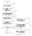
次に、このような実施形態の表面検査装置1を使用して自動車の表面検査を行う方法を、準備段階について図3、実際の検査段階について図4のフローチャートを参照して説明する。
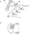
まず、準備作業として、ロボット23,24に接続された動作処理部25に検査ルートと複数の撮像地点とを記憶させるティーチングステップ(ステップs1)を実行する。ティーチング方法としては周知の方法を用いることができる。例えば、オペレータが制御操作盤の操作パネルを用いてロボット23,24を動作させ、走査経路を記憶させる方法がある。この方法は、オペレータがロボットコントローラを介してロボット駆動用モータを駆動し、図5(A)に示すように車両ボディ11を構成するボンネットやルーフの上の撮像地点P1〜P4に沿ってロボットアームの先端を移動させることにより行う。走査経路P1〜P4に付した矢印は、ロボット23,24の先端の移動方向(走査方向)を示す。Next, a method for performing surface inspection of an automobile using the
First, as a preparatory work, a teaching step (step s1) is executed in which the
このようなティーチングプログラム中、複数の撮像ポイントを登録し、各撮像ポイントにおいてロボット23,24の先端に設けられたCCDカメラ22が撮像ポイントにおける照明手段21からの反射光を検出し、検出した光学情報をパルス信号として出力する。ティーチングの結果、検査ルートと複数の撮像ポイントとが動作プログラムとしてロボットに接続された動作処理部25のティーチング部25bに記憶される。
なお、ティーチングに際し、実際のロボット23,24を稼動させることなく、ソリッドモデル等による3次元CAD上で教示を行う、いわゆるオフラインティーチングの手法によって検査ルートと複数の撮像地点とを作成してもよい。In such a teaching program, a plurality of imaging points are registered, and at each imaging point, the
In teaching, an inspection route and a plurality of imaging points may be created by a so-called offline teaching method in which teaching is performed on a three-dimensional CAD using a solid model or the like without operating the
次に、学習ステップ(ステップs2)を実行する。このステップは、ボディが停止している状態でロボット23,24を、先の動作プログラムを実行し、各撮像ポイントにおけるボディ上の座標データを座標情報格納部4bに送信し格納することにより行う。具体的には、ティーチング部25aから駆動処理部25bに命令を送ることにより上述の検査ルートの通りにロボットアーム23,24を動作させ(ステップs21)、登録された撮像ポイントにおいては動作処理部25からその撮像ポイントにおけるボディ上の座標データをデータ処理部4の座標情報格納部4bに送信する(ステップs22)。座標情報格納部4bは、各座標データと、その座標値が何度目のパルス信号発信に対応しているか、すなわち撮像が行われる順番のデータを図6に示すようなデータベース41として記憶する(ステップs23)。なお、このデータベースは各ロボットにつき一部作成される。 Next, a learning step (step s2) is executed. This step is performed by executing the previous operation program for the
続いて、実際の表面検査時に行われる検査ステップ(ステップs3)について図4のフローチャートを参照して説明する。
まず、動作処理部25は先の動作プログラムを実行する(ステップs31)。すると、ロボットアーム23,24は図5(A)に示すように、CCDカメラ22がボディ上の撮像ポイントP1,P2,P3,P4を通過するように動作する。その際、CCDカメラ22は撮像ポイントP1,P2,P3,P4において照明手段21からの反射光を検出し、得られた光学情報をパルス信号に変換して出力する(ステップs32)。Next, the inspection step (step s3) performed at the time of actual surface inspection will be described with reference to the flowchart of FIG.
First, the
このパルス信号は撮像信号処理部26に送信される。撮像信号処理部26において、判断部26bは、パルス信号を判断テーブル26aと照らし合わせることにより、その撮像ポイントにおけるボディ上の欠陥の有無を判定する。すなわち、そのパルス信号レベルを判断テーブル26aの基準値に照らして例えば4段階に分類する(ステップs33)。 This pulse signal is transmitted to the imaging
こうして得られた情報は撮像信号としてデータ処理部4の関連付け処理部4aに送信される。関連付け処理部4aは、撮像信号の送信された順番を座標情報格納部4bに格納された順番データと照らし合わせることにより撮像信号と座標データとを関連付け(ステップs34)、検査結果表示端末31へ送信する(ステップs35)。このように、本実施形態は、撮像地点においてロボットアーム23,24が座標データを出力しない点において従来例の検査方法と異なる。すなわち、座標データを出力するために要する時間を省略することにより、迅速な検査を可能とするものである。 The information thus obtained is transmitted to the
次に、検査結果表示端末31により出力ステップ(ステップs4)が行われる。まず、検査結果表示端末31の出力処理部31aは、座標データとボディフォーマット格納部31bに格納されたボディフォーマットとを照らし合わせ、撮像信号が得られた撮像ポイントがボディ上のどの位置に相当するかを特定するマッピングを行う。すなわち、出力処理部31aは、ボディ表面上に欠陥のあるデータを抽出し(ステップs41)、この画像データに関連付けられた座標データから欠陥の存在する座標を割り出す(ステップs42)。続いて、図1に示すように、ボディの各部を表した検査帳簿34上において欠陥の存在を示す撮像データが得られた撮像ポイントに該当する部分に、欠陥の大きさを3段階で示す○、△、×のいずれかのマークを描画する(ステップs43)。なお、欠陥の存在しない撮像ポイントについては何も描画しない。この検査帳簿34は、検査結果表示端末31のディスプレイに表示されると共に、プリンタ32により印刷される(ステップs44)。 Next, an output step (step s4) is performed by the inspection
本実施形態の表面検査装置2を使用して表面検査を実施すれば、ロボットを例えば線速350mm/sといった高速で動作させながら表面検査を行うことができるので、ロボットの台数を増やすことなくタクト内で表面検査を行うことができる。また、ロボットをポイントごとに止める必要がなく、加減速のある不安定な動きとなることを避けて、一定の精度で表面検査を行うことができる。 If surface inspection is performed using the
以上説明したように、本発明の表面検査装置及び表面検査方法は、撮像信号の送信された順番を順番データと照らし合わせ撮像信号と座標データとを関連付けることにより、撮像ポイントにおいてロボットアームもしくは動作処理部が座標値を出力することなく表面検査を行うことを実現したものであり、その主旨を逸脱しない範囲内において様々な形態で実施することができる。
例えば、パルス信号から欠陥の有無を判定する処理は、撮像信号処理部、データ処理部または出力処理部のいずれで行ってもよいし、撮像信号処理部、データ処理部及び出力処理部は一の端末に内蔵されていてもよい。また、水平面検査ロボット及び垂直面検査ロボット並びにこれらロボットのカメラにそれぞれ接続された撮像信号処理部は、実施形態の個数に限られない。As described above, the surface inspection apparatus and the surface inspection method of the present invention compare the order in which the imaging signals are transmitted with the order data and associate the imaging signals with the coordinate data, thereby performing the robot arm or operation processing at the imaging point. The unit realizes the surface inspection without outputting coordinate values, and can be implemented in various forms without departing from the gist thereof.
For example, the process for determining the presence or absence of a defect from a pulse signal may be performed by any of the imaging signal processing unit, the data processing unit, and the output processing unit, and the imaging signal processing unit, the data processing unit, and the output processing unit are one. It may be built in the terminal. Further, the horizontal plane inspection robot, the vertical plane inspection robot, and the imaging signal processing units connected to the cameras of these robots are not limited to the number of embodiments.
1 表面検査装置
2 検査部
3 検査結果出力部
4 データ処理部
4a 関連付け処理部
4b 座標情報格納部
22 CCDカメラ
23 水平面検査ロボット
24 垂直面検査ロボット
25 動作処理部
25a ティーチング部
25b 駆動処理部
26 撮像信号処理部
26a 判断テーブル
26b 判断部
31 検査結果表示端末
32 プリンタ
41 データベース
P1〜P4 撮像地点DESCRIPTION OF
Claims (5)
Translated fromJapanese上記ロボットアームの検査ルートと複数の上記撮像地点とが予め設定され、該検査ルートに沿って上記ロボットアームを移動させながら該複数の撮像地点で順番に上記撮像手段に撮像させる動作処理部と、
上記動作処理部に予め設定された上記複数の撮像地点の各座標データと撮像が行われる順番データとが格納された情報格納部と、
上記撮像手段から順番に送信される上記各撮像地点の撮像信号を基準値に照らし合わせて、該各撮像地点における欠陥の有無を判定する検出部と、
上記検出部から上記撮像信号が送信された順番と上記情報格納部に格納された順番データとを照らし合わせ、上記検出部から送信された撮像信号と上記座標データとを関連付ける関連付け処理部と、
上記関連付け処理部で上記撮像信号に関連付けられた上記座標データから上記車両ボディにおける欠陥の位置を特定した検査結果を出力する検査結果出力部と、を有する車両ボディの表面検査装置。A robotarm with a Rutotomoni multiple joints provided on the tip and imaging meansfor obtaining an image pickup signal by imaging animaging point on the illumination means andsaid vehicle body for irradiating illumination light tothe vehicle body,
Inspection route of the robot arm and a plurality of the imaging point is set in advance, and the operation processing unit for imaging in said imaging meansin turnthe plurality of imaging points while moving the robot arm alongthe test route,
An information storage unit and the order data is storedfor each coordinate data and imaging of a presetplurality of imaging pointsto the operation processing unit is carried out,
A detection unit that determines the presence or absence of a defect at each imaging point by comparing the imaging signal of each imaging point sequentially transmitted from the imaging unit with a reference value;
Anassociation processing unit that compares theorder in which theimaging signals are transmittedfrom the detection unit with theorder data stored in theinformation storage unit ,and associates the imaging signals transmitted from the detection unit with the coordinate data ;
Avehicle body surface inspection device comprising:an inspection result output unit that outputs an inspection result specifying a position of a defect in the vehicle body from the coordinate data associated with the imaging signal by the association processing unit .
上記ロボットアームを移動させながら、検査ルートと複数の撮像地点とを該ロボットアームに接続された動作処理部に予め設定して記憶させるティーチングステップと、
予め設定された上記複数の撮像地点の各座標データを、撮像が行われる順にデータ処理部に送信し、該座標データと撮像が行われる順番データとを上記データ処理部の情報格納部に格納する学習ステップと、
上記ロボットアームが上記検査ルートに沿って動作しつつ、上記撮像手段が各撮像地点において順番に撮像し、得られた撮像信号を順番に上記データ処理部に送信し、送信された各撮像地点の撮像信号を基準値に照らし合わせて該各撮像地点における欠陥の有無を検出部で判定し、上記撮像信号が送信された順番と上記順番データとを照らし合わせ、上記検出部から送信された撮像信号と座標データとを関連付ける検査ステップと、
撮像信号に関連付けられた上記座標データから上記車両ボディにおける欠陥の位置を特定した検査結果を出力する出力ステップと、を含む車両ボディの表面検査方法。
Image pickup means provided at the distal end of a robot armhaving a plurality ofjoints, the detection unit based on imaging signals obtained bythe imaging means onthe vehicle body surface inspection method for detecting defects present on theimaging point on the vehicle body There,
While moving the robot arm, the teaching steps of storinga plurality of image pickup point and the inspection routeset in advance to the operation processing unit connected to the robot arm,
Storingcoordinate data ofa predetermined plurality of imaging points, and transmitted to the data processing unit in the order in which the imaging is performed, and the order data in theinformation storage unit of the data processing unitto which the coordinate data and the imaging is performed Learning steps,
While the robot arm is operated along the test route, the imaging means takesan imagesequentially in each imagingpoint the imagingsignal obtained is transmitted to the data processing unitin order,of each imaging point sent The imaging signal is compared with a reference value, the presence or absence of a defect at each imaging point is determined by the detection unit, the order in which the imaging signals are transmitted is compared with the order data, and the imaging signaltransmitted from the detection unit An inspection step for associating the coordinate data with the coordinate data;
Avehicle body surface inspection method comprising:an output step of outputting an inspection result specifying a position of a defect in the vehicle body from the coordinate data associated with an imaging signal .
Priority Applications (1)
| Application Number | Priority Date | Filing Date | Title |
|---|---|---|---|
| JP2007173266AJP4862765B2 (en) | 2007-06-29 | 2007-06-29 | Surface inspection apparatus and surface inspection method |
Applications Claiming Priority (1)
| Application Number | Priority Date | Filing Date | Title |
|---|---|---|---|
| JP2007173266AJP4862765B2 (en) | 2007-06-29 | 2007-06-29 | Surface inspection apparatus and surface inspection method |
Publications (2)
| Publication Number | Publication Date |
|---|---|
| JP2009014357A JP2009014357A (en) | 2009-01-22 |
| JP4862765B2true JP4862765B2 (en) | 2012-01-25 |
Family
ID=40355458
Family Applications (1)
| Application Number | Title | Priority Date | Filing Date |
|---|---|---|---|
| JP2007173266AExpired - Fee RelatedJP4862765B2 (en) | 2007-06-29 | 2007-06-29 | Surface inspection apparatus and surface inspection method |
Country Status (1)
| Country | Link |
|---|---|
| JP (1) | JP4862765B2 (en) |
Families Citing this family (18)
| Publication number | Priority date | Publication date | Assignee | Title |
|---|---|---|---|---|
| KR101446914B1 (en) | 2013-03-29 | 2014-10-07 | 아진산업(주) | Robot arm for vision test |
| WO2015011782A1 (en)* | 2013-07-23 | 2015-01-29 | 株式会社安川電機 | Inspection apparatus |
| JP6549644B2 (en) | 2017-06-27 | 2019-07-24 | ファナック株式会社 | Machine learning apparatus, robot control system and machine learning method |
| JP6705777B2 (en) | 2017-07-10 | 2020-06-03 | ファナック株式会社 | Machine learning device, inspection device and machine learning method |
| JP7073785B2 (en)* | 2018-03-05 | 2022-05-24 | オムロン株式会社 | Image inspection equipment, image inspection method and image inspection program |
| JP6918756B2 (en)* | 2018-08-31 | 2021-08-11 | ファナック株式会社 | Detection system |
| WO2021054059A1 (en)* | 2019-09-20 | 2021-03-25 | 株式会社Screenホールディングス | Imaging device |
| CN110907455B (en)* | 2019-12-29 | 2024-05-07 | 常州微亿智造科技有限公司 | Three-body machine for detecting appearance of computer bottom cover and detection method thereof |
| CN111830052A (en)* | 2020-06-01 | 2020-10-27 | 涡阳县沪涡多孔矸石砖有限公司 | Flaw detection system for hollow brick |
| CN113125463B (en)* | 2021-04-25 | 2023-03-10 | 济南大学 | Teaching method and device for detecting weld defects of automobile hub |
| CN115479543A (en)* | 2021-06-16 | 2022-12-16 | 欣竑科技有限公司 | Learning type tool checking apparatus and operation method thereof |
| KR102578615B1 (en)* | 2021-08-09 | 2023-09-13 | 정현종 | A Non-Contacting Type of a 3D Measuring Robot for Determining a Distortion Condition of a Vehicle and a System for Repairing a Vehicle |
| JP7700070B2 (en)* | 2022-03-17 | 2025-06-30 | 株式会社東芝 | OPTICAL INSPECTION METHOD, OPTICAL INSPECTION PROGRAM, PROCESSING APPARATUS, AND OPTICAL INSPECTION APPARATUS |
| CN114705691B (en)* | 2022-06-06 | 2022-09-06 | 深圳向一智控科技有限公司 | Industrial machine vision control method and device |
| TWI828545B (en)* | 2023-02-22 | 2024-01-01 | 開必拓數據股份有限公司 | Flexible and intuitive system for configuring automated visual inspection system |
| CN116684724B (en)* | 2023-05-19 | 2024-04-09 | 中科慧远视觉技术(洛阳)有限公司 | Workpiece image acquisition control method and device, workpiece detection equipment and storage medium |
| CN116297531B (en)* | 2023-05-22 | 2023-08-01 | 中科慧远视觉技术(北京)有限公司 | Machine vision detection method, system, medium and equipment |
| CN117798936B (en)* | 2024-02-29 | 2024-06-07 | 卡奥斯工业智能研究院(青岛)有限公司 | Control method and device for mechanical arm cluster, electronic equipment and storage medium |
Family Cites Families (3)
| Publication number | Priority date | Publication date | Assignee | Title |
|---|---|---|---|---|
| JP3204692B2 (en)* | 1991-08-09 | 2001-09-04 | マツダ株式会社 | How to capture continuous images |
| JP2006038550A (en)* | 2004-07-26 | 2006-02-09 | Kanto Auto Works Ltd | Painted surface inspection device |
| JP4460485B2 (en)* | 2005-04-27 | 2010-05-12 | シーケーディ株式会社 | Order optimization device and substrate inspection device |
- 2007
- 2007-06-29JPJP2007173266Apatent/JP4862765B2/ennot_activeExpired - Fee Related
Also Published As
| Publication number | Publication date |
|---|---|
| JP2009014357A (en) | 2009-01-22 |
Similar Documents
| Publication | Publication Date | Title |
|---|---|---|
| JP4862765B2 (en) | Surface inspection apparatus and surface inspection method | |
| CN1922474B (en) | Method and system for inspecting surfaces | |
| WO2018066576A1 (en) | Appearance inspecting method | |
| JP2020035396A (en) | Sensing system, work system, presentation method of augmented reality image, and program | |
| US10607337B2 (en) | Object inspection system and object inspection method | |
| JP2008124293A (en) | Imaging apparatus with image processing function and inspection system | |
| JP2006234553A (en) | Visual inspection device and visual inspection method | |
| JP2007523334A (en) | Defect position identification method and marking system | |
| CN113495073A (en) | Auto-focus function for vision inspection system | |
| JP5686012B2 (en) | Surface defect inspection apparatus and method | |
| JP7608398B2 (en) | ROBOT TEACHING DEVICE, VISUAL INSPECTION SYSTEM, ROBOT TEACHING METHOD AND PROGRAM | |
| JP2786070B2 (en) | Inspection method and apparatus for transparent plate | |
| JP2008160635A (en) | Camera state detection method | |
| JP2011149814A (en) | Coating inspection device and coating inspection method | |
| JP7440975B2 (en) | Imaging device and identification method | |
| KR20180103467A (en) | System and method for estimating position of end point of welding robot using 3d camera | |
| CN112444283A (en) | Detection apparatus for vehicle assembly and vehicle assembly production system | |
| CN115922713A (en) | Vehicle configuration error-proofing detection method based on multi-mechanical-arm cooperation | |
| CN115963113A (en) | Glue detection method and system for workpiece glue tank | |
| JPH09192983A (en) | Tool attrition amount measuring method | |
| JP2008014822A (en) | Inspection device for plate body | |
| JP7450691B1 (en) | Interference discrimination display system, interference discrimination display method, and interference discrimination display program | |
| JPH11207483A (en) | Laser beam machining device | |
| JP4378199B2 (en) | Scan setting method for surface inspection apparatus | |
| JP2527233Y2 (en) | Work position detector |
Legal Events
| Date | Code | Title | Description |
|---|---|---|---|
| A977 | Report on retrieval | Free format text:JAPANESE INTERMEDIATE CODE: A971007 Effective date:20110112 | |
| A131 | Notification of reasons for refusal | Free format text:JAPANESE INTERMEDIATE CODE: A131 Effective date:20110118 | |
| A521 | Written amendment | Free format text:JAPANESE INTERMEDIATE CODE: A523 Effective date:20110322 | |
| TRDD | Decision of grant or rejection written | ||
| A01 | Written decision to grant a patent or to grant a registration (utility model) | Free format text:JAPANESE INTERMEDIATE CODE: A01 Effective date:20111018 | |
| A01 | Written decision to grant a patent or to grant a registration (utility model) | Free format text:JAPANESE INTERMEDIATE CODE: A01 | |
| A61 | First payment of annual fees (during grant procedure) | Free format text:JAPANESE INTERMEDIATE CODE: A61 Effective date:20111024 | |
| FPAY | Renewal fee payment (event date is renewal date of database) | Free format text:PAYMENT UNTIL: 20141118 Year of fee payment:3 | |
| R150 | Certificate of patent or registration of utility model | Free format text:JAPANESE INTERMEDIATE CODE: R150 | |
| FPAY | Renewal fee payment (event date is renewal date of database) | Free format text:PAYMENT UNTIL: 20141118 Year of fee payment:3 | |
| S531 | Written request for registration of change of domicile | Free format text:JAPANESE INTERMEDIATE CODE: R313531 | |
| S533 | Written request for registration of change of name | Free format text:JAPANESE INTERMEDIATE CODE: R313533 | |
| FPAY | Renewal fee payment (event date is renewal date of database) | Free format text:PAYMENT UNTIL: 20141118 Year of fee payment:3 | |
| R350 | Written notification of registration of transfer | Free format text:JAPANESE INTERMEDIATE CODE: R350 | |
| LAPS | Cancellation because of no payment of annual fees |