JP4861787B2 - Reagent container and reagent container holder - Google Patents
Reagent container and reagent container holderDownload PDFInfo
- Publication number
- JP4861787B2 JP4861787B2JP2006276464AJP2006276464AJP4861787B2JP 4861787 B2JP4861787 B2JP 4861787B2JP 2006276464 AJP2006276464 AJP 2006276464AJP 2006276464 AJP2006276464 AJP 2006276464AJP 4861787 B2JP4861787 B2JP 4861787B2
- Authority
- JP
- Japan
- Prior art keywords
- reagent
- reagent container
- opening
- container
- holding
- Prior art date
- Legal status (The legal status is an assumption and is not a legal conclusion. Google has not performed a legal analysis and makes no representation as to the accuracy of the status listed.)
- Expired - Fee Related
Links
Images


Classifications
- G—PHYSICS
- G01—MEASURING; TESTING
- G01N—INVESTIGATING OR ANALYSING MATERIALS BY DETERMINING THEIR CHEMICAL OR PHYSICAL PROPERTIES
- G01N35/00—Automatic analysis not limited to methods or materials provided for in any single one of groups G01N1/00 - G01N33/00; Handling materials therefor
- G01N35/02—Automatic analysis not limited to methods or materials provided for in any single one of groups G01N1/00 - G01N33/00; Handling materials therefor using a plurality of sample containers moved by a conveyor system past one or more treatment or analysis stations
- G01N35/025—Automatic analysis not limited to methods or materials provided for in any single one of groups G01N1/00 - G01N33/00; Handling materials therefor using a plurality of sample containers moved by a conveyor system past one or more treatment or analysis stations having a carousel or turntable for reaction cells or cuvettes
- B—PERFORMING OPERATIONS; TRANSPORTING
- B01—PHYSICAL OR CHEMICAL PROCESSES OR APPARATUS IN GENERAL
- B01L—CHEMICAL OR PHYSICAL LABORATORY APPARATUS FOR GENERAL USE
- B01L3/00—Containers or dishes for laboratory use, e.g. laboratory glassware; Droppers
- B01L3/50—Containers for the purpose of retaining a material to be analysed, e.g. test tubes
- B01L3/508—Containers for the purpose of retaining a material to be analysed, e.g. test tubes rigid containers not provided for above
- B01L3/5082—Test tubes per se
- B01L3/50825—Closing or opening means, corks, bungs
- B—PERFORMING OPERATIONS; TRANSPORTING
- B01—PHYSICAL OR CHEMICAL PROCESSES OR APPARATUS IN GENERAL
- B01L—CHEMICAL OR PHYSICAL LABORATORY APPARATUS FOR GENERAL USE
- B01L9/00—Supporting devices; Holding devices
- B01L9/06—Test-tube stands; Test-tube holders
- G—PHYSICS
- G01—MEASURING; TESTING
- G01N—INVESTIGATING OR ANALYSING MATERIALS BY DETERMINING THEIR CHEMICAL OR PHYSICAL PROPERTIES
- G01N35/00—Automatic analysis not limited to methods or materials provided for in any single one of groups G01N1/00 - G01N33/00; Handling materials therefor
- G01N35/02—Automatic analysis not limited to methods or materials provided for in any single one of groups G01N1/00 - G01N33/00; Handling materials therefor using a plurality of sample containers moved by a conveyor system past one or more treatment or analysis stations
- G01N35/04—Details of the conveyor system
- G01N2035/0401—Sample carriers, cuvettes or reaction vessels
- G01N2035/0403—Sample carriers with closing or sealing means
- G01N2035/0405—Sample carriers with closing or sealing means manipulating closing or opening means, e.g. stoppers, screw caps, lids or covers
Landscapes
- Chemical & Material Sciences (AREA)
- Chemical Kinetics & Catalysis (AREA)
- Physics & Mathematics (AREA)
- Health & Medical Sciences (AREA)
- Life Sciences & Earth Sciences (AREA)
- Analytical Chemistry (AREA)
- Biochemistry (AREA)
- General Health & Medical Sciences (AREA)
- General Physics & Mathematics (AREA)
- Immunology (AREA)
- Pathology (AREA)
- Automatic Analysis And Handling Materials Therefor (AREA)
Description
Translated fromJapaneseこの発明は、試薬収容具および試薬容器保持具に関し、特に、試薬が収容された状態で、開口が密封される試薬収容具および試薬容器保持具に関する。 The present invention relates to a reagent container and a reagent container holder, and more particularly to a reagent container and a reagent container holder whose openings are sealed in a state in which the reagent is accommodated.
従来、試薬が収容された状態で、開口が密封される試薬収容具が知られている(たとえば、特許文献1参照)。 Conventionally, a reagent container in which an opening is sealed in a state where a reagent is stored is known (for example, see Patent Document 1).
上記特許文献1に記載の試薬収容具は、試薬が収容される試薬容器と、試薬容器に取り付けられるキャップとを備えている。また、キャップは、試薬容器の開口近傍に配置され、中心から外周に向けて放射状にスリットが形成された弾性体からなる円板状の封止体と、上方から押圧されることにより下方に移動して、封止体のスリットを下方に押し広げて開口させる開閉部材とを含んでいる。また、開閉部材は、バネ部材により上方に付勢されている。 The reagent container described in Patent Document 1 includes a reagent container for storing a reagent and a cap attached to the reagent container. The cap is arranged near the opening of the reagent container, and moves downward when pressed from above with a disk-shaped sealing body made of an elastic body having slits radially formed from the center toward the outer periphery. And the opening-and-closing member which expands and opens the slit of a sealing body downward is included. The opening / closing member is urged upward by a spring member.
上記特許文献1では、試薬の分取時には、開閉部材を上方から押圧することにより、封止体のスリットが開口されて試薬の分取が可能な状態となる。そして、試薬の分取の後、開閉部材への押圧を解除することにより開閉部材がバネ部材による付勢力によって上方に移動されて、弾性体からなる封止体の押し広げられていたスリットの形状が復元する。これにより、試薬容器の開口が閉じられるように構成されている。 In Patent Document 1, when the reagent is dispensed, the opening / closing member is pressed from above, so that the slit of the sealing body is opened and the reagent can be dispensed. Then, after dispensing the reagent, by releasing the pressure on the opening and closing member, the opening and closing member is moved upward by the urging force of the spring member, and the shape of the slit that has been spread out of the sealing body made of an elastic body Will restore. Thereby, it is comprised so that the opening of a reagent container may be closed.
しかしながら、上記特許文献1の試薬収容具では、押し広げられていた封止体のスリットの形状が弾性力によって復元することにより試薬容器が閉じられるように構成されているため、試薬容器を密封することができない。このため、ユーザに試薬を供給するときには、試薬容器の開口が密封専用のキャップで密封されており、ユーザは、試薬の使用時(試薬の吸引時)に試薬容器の密封専用のキャップを取り外して、前述のキャップに取り替える必要がある。そのため、キャップを取り替える際、試薬容器に収容されている試薬を汚染したり、または、ユーザに試薬が付着するといった汚染事故が発生する場合があるという問題点がある。 However, the reagent container of Patent Document 1 is configured so that the reagent container is closed by restoring the shape of the slit of the sealing body that has been spread out by elastic force, and therefore the reagent container is sealed. I can't. For this reason, when supplying a reagent to the user, the opening of the reagent container is sealed with a cap dedicated to sealing, and the user removes the cap dedicated to sealing the reagent container when using the reagent (when aspirating the reagent). It is necessary to replace the cap described above. Therefore, when replacing the cap, there is a problem that a contamination accident such as contamination of the reagent contained in the reagent container or attachment of the reagent to the user may occur.
この発明は、上記のような課題を解決するためになされたものであり、この発明の1つの目的は、自動分析装置に用いられる試薬収容具および試薬容器保持具であって、汚染事故が発生することを抑制し、試薬容器が開封された状態においても使用者が容易に扱うことができ、自動分析装置による試薬吸引が可能な試薬収容具および試薬容器保持具を提供することである。The present invention has been made to solve the above-described problems, and one object of the present invention is areagent container and a reagent container holder used in anautomatic analyzer, and a contamination accident occurs. it suppressesthe, can also be user to easily handle in a state in which the reagent container is opened, it is to provide acapable reagent-containing assembly and the reagent container holder trialKusuri吸 argumentby autoanalyzer .
この発明の第1の局面による試薬収容具は、試薬を吸引するための吸引管を備え、吸引管によって吸引された試薬を用いて検体を分析する自動分析装置に用いられる試薬収容具であって、内部に試薬が収容された状態で開口がシール部材により封止された試薬容器、試薬容器を保持する試薬容器保持部、および第1係合部を有する試薬収容部と、吸引管が挿入される吸引孔、試薬容器内に進入することによりシール部材を突き破る突部、および第1係合部と係合可能な第2係合部を有し、一端が開放された箱状に形成されており、その開放端から試薬保持部に保持されている試薬容器を収容可能に形成されている開封部と、を備え、開封部の開放端から試薬容器保持部に保持されている試薬容器を収容させることにより、突部がシール部材を突き破るとともに、第1係合部と第2係合部が係合して開封部と試薬収容部が一体になり、吸引孔と、突部によってシール部材が突き破られた開口とを介して、吸引管によって試薬容器内の試薬を吸引することが可能に構成されている。A reagent container according to a first aspect of the present invention is areagent container used in an automatic analyzer that includes a suction tube for sucking a reagent and analyzes a sample using the reagent sucked by the suction tube. ,the reagent container openingis sealed by a sealing member in a state where the reagentinside isaccommodated, the reagent container holder for holding a reagent container, and a reagent storage section thathaving a first engagement portion,the suction tube It has a suction hole to be inserted, a projectionthat breaks through the seal member by entering the reagent container, and a second engagement portion thatcan be engagedwith the first engagement portion, andis formed in a box shape with one end open. Andan opening partformed so as to accommodate the reagent container held in the reagent holding part from the open end thereof, and thereagent container held in the reagent container holding part from the open end of theopening part By accommodating the projecting part, the projecting part With break can, the tearing portion and a reagent accommodating portion second engaging portion and the first engaging portion is engaged with is integrated, via a suction hole and an opening which is sealed member is pierced by the projections The reagentin the reagentcontainer can be suckedby thesuction tube .
この第1の局面による試薬収容具では、開封部を試薬収容部に保持することにより、試薬収容部に収容されている試薬を吸引孔と開口とを介して吸引することができる。これにより、使用者がシール部材を剥がすなどの作業を行う必要がないため、試薬収容部に収容されている試薬を汚染したり、または、使用者に試薬が付着するという汚染事故の発生を抑制しながら試薬の吸引を行うことができる。 In the reagent container according to the first aspect, the reagent housed in the reagent container can be sucked through the suction hole and the opening by holding the opening part in the reagent container. This eliminates the need for the user to perform work such as peeling off the sealing member, thereby preventing the occurrence of a contamination accident in which the reagent contained in the reagent container is contaminated or the reagent adheres to the user. The reagent can be aspirated while being.
この第1の局面による試薬収容具において、好ましくは、試薬収容部は、突部によって突き破られたシール部材が収容されるシール収容部を有する。このように構成すれば、突き破られたシール部材を試薬の吸引を行う器具の通過経路に残らないようにシール収容部に収容することができるので、突き破られたシール部材の影響を受けることなく、開口および吸引孔を介して試薬を吸引することができる。 In the reagent container according to the first aspect, preferably, the reagent container has a seal container in which a seal member pierced by the protrusion is stored. If comprised in this way, since the pierced seal member can be accommodated in the seal accommodating portion so that it does not remain in the passage of the instrument for aspirating the reagent, it is affected by the pierced seal member. The reagent can be sucked through the opening and the suction hole.
この第1の局面による試薬収容具において、好ましくは、開封部は、試薬収容部に対して、突部がシール部材を突き破って試薬収容部の開口内に位置する第1位置と、突部がシール部材から離間している第2位置とに位置することが可能に構成されている。このように構成すれば、試薬収容具を使用する前には、開封部を突部がシール部材から離間している第2位置に保持し、試薬収容具を使用する際に、開封部を突部がシール部材を突き破って試薬収容部の開口内に位置する第1位置に保持することができる。これにより、たとえば、開封部が第2位置に保持された状態で、試薬収容具の保存、運搬などを行い、開封部を第1位置に保持して試薬収容具を使用(試薬を吸引)することができるので、使用者の利便性を増すことができる。In the reagent container according to the first aspect, preferably, the opening portion has a first position where the protrusion breaks through the seal member and is located in the opening of the reagent storage portion with respect to the reagent storage portion.It is configured to be ableto be located at a second position that is separated from the seal member. According to this structure, before using the reagent container, the opening is held at the second position where the protrusion is separated from the seal member, and the opening is protruded when the reagent container is used. The portion can pierce the seal member and be held at the first position located in the opening of the reagent storage portion. Thereby, for example, the reagent container is stored and transported in a state where the opening part is held at the second position, and the reagent container is used (a reagent is sucked) while the opening part is held at the first position. Therefore, the convenience for the user can be increased.
この第1の局面による試薬収容具において、好ましくは、開閉機構をさらに備える自動分析装置において使用される試薬収容具であって、開封部は、開閉機構によって開閉されることで吸引孔を開放および閉鎖可能な蓋部をさらに含み、開閉機構によって蓋部が開けられ開放された吸引孔と、シール部材が突き破られて開放された開口とを介して、吸引管によって試薬容器内の試薬を吸引することが可能に構成されている。このように構成すれば、シール部材が突部により突き破られた後においても、蓋部により吸引孔を開閉することができる。これにより、試薬の吸引時には蓋部を開いて試薬を吸引し、試薬の非使用時には、蓋部を閉じて試薬を密閉した状態で保存することができる。The reagent container according to the first aspect is preferablya reagent container used in an automatic analyzer further provided with an opening /closing mechanism, wherein the opening portion is opened andclosed by the opening / closing mechanism toopen andclose the suction hole.seefurther including aclosablelid, and a suction hole that is the lid portion is opened opened by the opening and closing mechanism, through an opening sealing member is opened is pierced, the reagent in the reagent container by a suction tube It is configured to be able to suck . If comprised in this way, even after the sealing member is pierced by the protrusion, the suction hole can be opened and closed by the lid. Thus, the lid can be opened to suck the reagent when the reagent is aspirated, and the reagent can be stored in a sealed state with the lid closed when the reagent is not used.
この場合、好ましくは、開封部は、スライドレールをさらに備え、蓋部は、スライドレール上を直線的にスライド移動することにより吸引孔を開放および閉鎖し、開閉機構は、スライドレール上において蓋部を所定方向にスライド移動させることにより吸引孔を開放および閉鎖するように構成されている。このように構成すれば、蓋部をスライドさせることにより、容易に吸引孔を開閉することができる。In this case, preferably,the opening portion further comprises a slide rail, lid,Tozashiopen- and closed suction holes bylinearlyslidingon the sliderail,the opening and closing mechanism on the slide rail The suction hole is opened and closed by sliding the lid in a predetermined direction . If comprised in this way, a suction hole can be opened and closed easily by sliding a cover part.
上記開封部が吸引孔を開閉可能な蓋部を含む構成において、好ましくは、蓋部は、吸引孔をシールするための弾性体からなるシート状部材を含む。このように構成すれば、蓋部を閉じて、弾性体からなるシート状部材を吸引孔に密着させることにより、容易に、試薬を密閉状態にすることができる。 In the configuration in which the opening part includes a lid part capable of opening and closing the suction hole, the lid part preferably includes a sheet-like member made of an elastic body for sealing the suction hole. If comprised in this way, a reagent can be easily made into a sealing state by closing a cover part and sticking the sheet-like member which consists of an elastic body to a suction hole.
この第1の局面による試薬収容具において、好ましくは、試薬容器保持部は、開封部の開放端を閉じるための底部を備え、開封部の開放端から試薬容器保持部に保持された試薬容器を収容させることにより、第1係合部と第2係合部が係合するとともに、開封部の開放端が試薬容器保持部の底部と当接して開封部と試薬収容部が一体になるよう構成されている。In the reagent container according to the first aspect, preferably, thereagent container holding part includes a bottom part for closing the open end of the opening part, and the reagent container held in the reagent container holding part from the open end of the opening part is removed. By being accommodated, the first engaging portion and the second engaging portion are engaged with each other, and the open end of the opening portion is in contact with the bottom portion of the reagent container holding portion so that the opening portion and the reagent storage portion are integrated. Has been .
この場合、好ましくは、試薬容器は、内面側に突出するとともに、上下方向および水平方向の少なくともいずれか一方に延びるように設けられた凸部を有する。このように構成すれば、試薬収容部が外部の装置などに搬送されるのに伴って試薬容器内で試薬が移動する際、移動しようとする試薬が試薬容器の内面側に設けられた凸部に当たることにより試薬の移動を抑制することができる。これにより、試薬が泡立つのを抑制することができる。 In this case, preferably, the reagent container has a convex portion that protrudes toward the inner surface side and extends in at least one of the vertical direction and the horizontal direction. According to this structure, when the reagent moves in the reagent container as the reagent container is transported to an external device or the like, the convex portion provided on the inner surface side of the reagent container is the reagent to be moved. The movement of the reagent can be suppressed by hitting. Thereby, it can suppress that a reagent bubbles.
上記第1の局面による試薬収容具において、好ましくは、試薬容器は、試薬容器保持部に係合するための第3係合部を有し、試薬容器保持部は、試薬容器の第3係合部に係合することによって試薬容器を保持するように構成されている。このように構成すれば、試薬容器の第3係合部により、容易に、試薬容器を試薬容器保持部に係合させて保持させることができる。In the reagent containeraccording to the first aspect , preferably, the reagent container has athird engagement part for engaging with the reagent container holding part, and the reagent container holding part is athird engagement ofthe reagent container. The reagent container is configured to be held by engaging the portion. If comprised in this way, a reagent container can be easily engaged with a reagent container holding part, and can be hold | maintained bythe 3rd engaging part of a reagent container.
この第1の局面による試薬収容具において、好ましくは、開封部は、吸引孔を有する筒部を含み、突部は、筒部の下部に設けられており、開封部の開放端から試薬容器保持部に保持された試薬容器を収容させることにより、突部によってシール部材が突き破られた開口に筒部が嵌入され、筒部を介して試薬容器の内部へ吸引管を挿入することが可能に構成されている。このように構成すれば、突部によってシール部材を突き破った後、開口に嵌入された筒部を介して、容易に、試薬容器の内部に吸引管を挿入することができる。In the reagent container according to the first aspect, preferably, the opening portion includes a cylindrical portion having a suction hole, and the protrusion is provided at a lower portion of the cylindrical portion, andholds the reagent container from the open end of theopening portion. By accommodating the reagent container held in the part, the cylindrical part is fitted intothe opening in whichthe seal member is piercedby the protrusion, and thesuction tube can be inserted into the reagentcontainer through the cylindrical part. It is configured. If comprised in this way, after piercing | piercing a seal member with a protrusion, asuction tube can be easily inserted in the inside of a reagentcontainer via the cylinder part inserted by opening.
この第1の局面による試薬収容具において、好ましくは、第2係合部は開封部に形成された係合孔であり、第1係合部は試薬容器保持部に形成され、係合孔に係合するように構成された係合部材である。In the reagent container according to the first aspect, preferably,the second engagement portion is an engagement hole formed in the opening portion, and the first engagement portion is formed in the reagent container holding portion, and is formed in the engagement hole. An engagement member configured to engage .
この第1の局面による試薬収容具において、好ましくは、開封部は、試薬容器内の試薬を視認可能なスリット部を含む。このように構成すれば、容易に、スリット部により試薬容器内の試薬の量を確認することができる。In the reagent-containing assembly according to the first aspect,preferably, the opening seal portion includes a slit portion visible reagent in the reagentcontainer. If comprised in this way, the quantity of the reagent in a reagentcontainer can be easily confirmed with a slit part.
上記第1の局面による試薬収容具において、好ましくは、試薬収容具を搬送するための搬送機構をさらに備える自動分析装置において使用される試薬収容具であって、試薬容器保持部は、その底部に搬送機構に係合するための第4係合部をさらに備える。このように構成すれば、第4係合部を外部の搬送機構に係合させることにより、容易に、外部の搬送機構によって試薬収容具を搬送することができる。Inthe reagent-containing assembly according to the first aspect, preferably,a reagent-containing assembly used in the automatic analyzer further comprising a transfer mechanism for transferring the reagent-containing assembly, the reagent container holdingunit, its bottomfurther comprising afourth engagement portion for engaging the transportmechanism. If comprised in this way, a reagent container can be easily conveyed by an external conveyancemechanism by engaging a4th engaging part with an external conveyancemechanism .
この発明の第2の局面による試薬収容具は、試薬を吸引するための吸引管を備え、吸引管によって吸引された試薬を用いて検体を分析する自動分析装置に用いられる試薬収容具であって、内部に試薬が収容された状態で開口がシール部材により封止された試薬容器と、第1係合部を有し、試薬容器を保持する保持部材と、吸引管が挿入される吸引孔、試薬容器内に進入することによりシール部材を突き破る突部、および第1係合部と係合可能に構成されている第2係合部を有し、一端が開放された箱状に形成されており、その開放端から保持部材により保持された試薬容器を収容可能に形成されているケースと、を備え、ケースの開放端から保持部材に保持された試薬容器を収容させることで、突部がシール部材を突き破るとともに、第1係合部と第2係合部が係合してケースと保持部材が一体になり、吸引孔と、シール部材が突き破られた開口とを介して、吸引管によって試薬容器内の試薬を吸引することが可能に構成されている。A reagent container according to a second aspect of the present invention is areagent container used in an automatic analyzer that includes a suction tube for sucking a reagent and analyzes a sample using the reagent sucked by the suction tube. , a reagent container openingis sealed by a sealing member in a state where the reagentinside is accommodated,it has a first engagement portion, and a holding member for holding the reagent container,the suction hole is suction tube is inserted, It has a projecting part that breaks through the seal member by entering the reagent container, and a second engaging part configured to be engageable with the first engaging part, and is formed in a box shape with one end open. Anda caseformed so that the reagent container held by the holding member can be accommodatedfrom the open end thereof, and the protrusionisaccommodated by accommodating the reagent container held by the holding member from the open end ofthe case.the sealing member TsukiyabuRutotomoni,first engagement Parts and engages the second engaging portion becomes integral casing and the holding member is a suction hole, through an opening sealing member has been pierced, aspirating the reagentin the reagent containerby a suction tube Is configured to be possible.
この第2の局面による試薬収容具では、試薬容器に収容されている試薬を吸引孔と開口とを介して吸引することができる。これにより、使用者がシール部材を剥がすなどの作業を行う必要がないため、試薬容器に収容されている試薬を汚染したり、または、使用者に試薬が付着するという汚染事故の発生を抑制しながら試薬の吸引を行うことができる。In the reagent-containing assembly according to the secondaspect, it is possible to aspirate the reagent contained in thereagent container via the suction hole and the opening. This eliminates the need for the user to perform work such as peeling off the seal member, thereby preventing the occurrence of a contamination accident in which the reagent contained in the reagent container is contaminated or the reagent adheres to the user. The reagent can be aspirated.
この発明の第3の局面による試薬容器保持具は、試薬を吸引するための吸引管を備え、吸引管によって吸引された試薬を用いて検体を分析する自動分析装置に用いられる試薬容器保持具であって、第1係合部を有し、内部に試薬が収容された状態で開口がシール部材により封止された試薬容器を保持可能に構成された保持部材と、吸引管が挿入される吸引孔、試薬容器内に進入することによりシール部材を突き破る突部、および第1係合部と係合可能に構成されている第2係合部を有し、一端が開放された箱状に形成されており、その開放端から保持部材によって保持された試薬容器を収容可能に形成されているケースと、を備え、ケースの開放端から保持部材に保持された試薬容器を収容させることで、突部がシール部材を突き破るとともに、第1係合部と第2係合部が係合してケースと保持部材とが一体になり、吸引孔と、シール部材が突き破られた開口とを介して、吸引管によって試薬容器内の試薬を吸引することが可能に構成されている。A reagent container holder according to a third aspect of the present invention is areagent container holder used in an automatic analyzer that includes a suction tube for sucking a reagent and analyzes a sample using the reagent sucked by the suction tube. there has a first engaging portion, a holdingmember openingiscapable of holdingconstituting asealed reagent container by the sealing memberin a state in which the reagent is accommodated,the suction tube is insertedintoIt has a suction hole, a protrusion that breaks through the seal member by entering the reagent container, and a second engagement part that is configured to be engageable with the first engagement part, and has a box shape with one end open. isformed,bythe from the open end and the casewhich is capable of accommodating form reagent container held by the holdingmember, comprises a,housing the reagent container held in the holding member from the open end of the case,Rutotomoprotrusion Tsukiyabua sealing member ,The second engaging portion and the first engagement portion is the case and the holding member and is integrally engaged with each other, and suction holes, through an opening sealing member was pierced, the reagentcontainerby a suction tube The reagent can be aspirated.
この第3の局面による試薬容器保持具では、上記のように、突部によってシール部材を突き破り、吸引孔と、シール部材が突き破られた開口とを介して、試薬容器から試薬を吸引することによって、試薬容器に収容されている試薬を吸引孔と開口とを介して吸引することができる。これにより、使用者がシール部材を剥がすなどの作業を行う必要がないため、試薬容器に収容されている試薬を汚染したり、または、使用者に試薬が付着するという汚染事故の発生を抑制しながら試薬の吸引を行うことができる。In the third reagent container holder according to aspects, as describedabove, it breaks through the seal member by thecollision portion, and a suction hole, through an opening sealing member has been pierced, aspirating the reagent from the reagent container It makesit possible to aspirate the reagent contained in thereagent container via the suction hole and the opening. This eliminates the need for the user to perform work such as peeling off the seal member, thereby preventing the occurrence of a contamination accident in which the reagent contained in the reagent container is contaminated or the reagent adheres to the user. The reagent can be aspirated.
以下、本発明を具体化した実施形態を図面に基づいて説明する。 DESCRIPTION OF THE PREFERRED EMBODIMENTS Embodiments embodying the present invention will be described below with reference to the drawings.
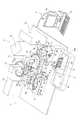
図1および図2は、それぞれ、本発明の一実施形態による試薬収容具が用いられる免疫分析装置の全体構成を示した斜視図および平面図である。図3〜図6および図20は、図1に示した一実施形態による免疫分析装置の各部の詳細を説明するための図である。まず、図1〜図6および図20を参照して、本発明の一実施形態による免疫分析装置1の全体構成について説明する。 FIG. 1 and FIG. 2 are a perspective view and a plan view, respectively, showing the overall configuration of an immune analyzer in which a reagent container according to an embodiment of the present invention is used. 3 to 6 and FIG. 20 are diagrams for explaining details of each part of the immune analyzer according to the embodiment shown in FIG. First, with reference to FIGS. 1-6 and FIG. 20, the whole structure of the immune analyzer 1 by one Embodiment of this invention is demonstrated.
本発明の一実施形態による免疫分析装置1は、血液などの検体を用いてB型肝炎、C型肝炎、腫瘍マーカおよび甲状腺ホルモンなど種々の項目の検査を行うための装置である。この免疫分析装置1では、測定対象である血液などの検体に含まれる抗原に結合した捕捉抗体(R1試薬)に磁性粒子(R2試薬)を結合させた後に、結合(Bound)した抗原、捕捉抗体および磁性粒子をBF(Bound Free)分離部14(図1および図2参照)の磁石(図示せず)に引き寄せることにより、未反応(Free)の捕捉抗体を含むR1試薬を除去する。そして、磁性粒子が結合した抗原と標識抗体(R3試薬)とを結合させた後に、結合(Bound)した磁性粒子、抗原および標識抗体をBF分離部14の磁石に引き寄せることにより、未反応(Free)の標識抗体を含むR3試薬を除去する。さらに、標識抗体との反応過程で発光する発光基質(R5試薬)を添加した後、標識抗体と発光基質との反応によって生じる発光量を測定する。このような過程を経て、標識抗体に結合する検体に含まれる抗原を定量的に測定している。 The immunoassay apparatus 1 according to an embodiment of the present invention is an apparatus for examining various items such as hepatitis B, hepatitis C, tumor marker, and thyroid hormone using a specimen such as blood. In this immunoassay apparatus 1, after binding magnetic particles (R2 reagent) to a capture antibody (R1 reagent) bound to an antigen contained in a sample such as blood to be measured, the bound antigen and the capture antibody Then, the R1 reagent containing the unreacted (Free) capture antibody is removed by attracting the magnetic particles to a magnet (not shown) of a BF (Bound Free) separation unit 14 (see FIGS. 1 and 2). Then, after binding the antigen to which the magnetic particles are bound and the labeled antibody (R3 reagent), the bound magnetic particles, the antigen and the labeled antibody are attracted to the magnet of the
この免疫分析装置1は、図1および図2に示すように、測定機構部2と、測定機構部2の前面側に配置された検体搬送部(サンプラ)3と、測定機構部2に電気的に接続されたPC(パーソナルコンピュータ)からなる制御装置4とを備えている。また、測定機構部2は、検体分注アーム5と、試薬設置部6および7と、試薬分注アーム8、9および10と、1次反応部11および2次反応部12と、キュベット供給部13と、BF分離部14と、検出部15とから構成されている。また、図3に示すように、測定機構部2における各機構(各種分注アーム、試薬設置部6および試薬設置部7など)は、測定機構部2に設けられた制御部2aにより制御されている。具体的には、制御部2aは、試薬設置部7に設けられた各種センサ(センサ60d、60fおよび原点検知センサ60eなど)の信号を受信するとともに、試薬設置部7に設けられた各種駆動源(ステッピングモータ53、63および駆動部73など)の駆動を制御している。また、搬送機構部3も制御部2aによって制御される。なお、各種分注アーム、各種センサおよび各種駆動源については後に詳細に説明する。 As shown in FIGS. 1 and 2, the immune analyzer 1 is electrically connected to the measurement mechanism unit 2, the sample transport unit (sampler) 3 disposed on the front side of the measurement mechanism unit 2, and the measurement mechanism unit 2. And a
制御部2aは、図4に示すように、CPU2bと、ROM2cと、RAM2dと、通信インターフェース2eとから主として構成されている。 As shown in FIG. 4, the
CPU2bは、ROM2cに記憶されているコンピュータプログラムおよびRAM2dに読み出されたコンピュータプログラムを実行することが可能である。ROM2cは、CPU2bに実行させるためのコンピュータプログラム及び当該コンピュータプログラムの実行に用いるデータ等を記憶している。RAM2dは、ROM2cに記憶しているコンピュータプログラムの読み出しに用いられる。また、これらのコンピュータプログラムを実行するときに、CPU2bの作業領域として利用される。 The CPU 2b can execute the computer program stored in the ROM 2c and the computer program read out to the RAM 2d. The ROM 2c stores a computer program to be executed by the CPU 2b and data used for executing the computer program. The RAM 2d is used for reading a computer program stored in the ROM 2c. Further, when these computer programs are executed, they are used as a work area of the CPU 2b.
通信インターフェース2eは、制御装置4に接続されており、検体の光学的な情報(標識抗体と発光基質との反応によって生じる発光量のデータ)を制御装置4に送信するとともに、制御装置4の制御部4aからの信号を受信するための機能を果たす。また、通信インターフェース2eは、搬送機構部3および測定機構部2の各部を駆動するためのCPU2bからの指令を送信するための機能を有する。 The communication interface 2e is connected to the
検体搬送部3は、図1および図2に示すように、検体を収容した複数の試験管100が載置されたラック101を、検体分注アーム5が検体を吸引する吸引位置1aに対応する位置まで搬送するように構成されている。この検体搬送部3は、未処理の検体を収容した試験管100が載置されたラック101をセットするためのラックセット部3aと、分注処理済みの検体を収容した試験管100が載置されたラック101を貯留するためのラック貯留部3bとを有している。そして、未処理の検体を収容した試験管100を検体分注アーム5の吸引位置1aに対応する位置まで搬送することにより、検体分注アーム5により試験管100内の血液などの検体の吸引が行われ、その後、その試験管100を載置したラック101がラック貯留部3bに貯留されるように構成されている。 As shown in FIGS. 1 and 2, the
制御装置4(図1参照)は、パーソナルコンピュータ(PC)などからなり、CPU、ROM、RAMなどからなる制御部4aと、表示部4bと、キーボード4cとを含んでいる。また、表示部4bは、検出部15から送信されたデジタル信号のデータを分析して得られた分析結果などを表示するために設けられている。 The control device 4 (see FIG. 1) includes a personal computer (PC) and the like, and includes a
次に、制御装置4の構成について説明する。制御装置4は、図5に示すように、制御部4aと、表示部4bと、キーボード4cとから主として構成されたコンピュータ401によって構成されている。制御部4aは、CPU401aと、ROM401bと、RAM401cと、ハードディスク401dと、読出装置401eと、入出力インタフェース401fと、通信インタフェース401gと、画像出力インタフェース401hとから主として構成されている。CPU401a、ROM401b、RAM401c、ハードディスク401d、読出装置401e、入出力インタフェース401f、通信インタフェース401g、および画像出力インタフェース401hは、バス401iによって接続されている。 Next, the configuration of the
CPU401aは、ROM401bに記憶されているコンピュータプログラムおよびRAM401cにロードされたコンピュータプログラムを実行することが可能である。そして、後述するようなアプリケーションプログラム404aをCPU401aが実行することにより、コンピュータ401が制御装置4として機能する。 The
ROM401bは、マスクROM、PROM、EPROM、EEPROMなどによって構成されており、CPU401aに実行されるコンピュータプログラムおよびこれに用いるデータなどが記録されている。 The
RAM401cは、SRAMまたはDRAMなどによって構成されている。RAM401cは、ROM401bおよびハードディスク401dに記録されているコンピュータプログラムの読み出しに用いられる。また、これらのコンピュータプログラムを実行するときに、CPU401aの作業領域として利用される。 The
ハードディスク401dは、オペレーティングシステムおよびアプリケーションプログラムなど、CPU401aに実行させるための種々のコンピュータプログラムおよびそのコンピュータプログラムの実行に用いるデータがインストールされている。本実施形態に係る免疫分析用のアプリケーションプログラム404aも、このハードディスク401dにインストールされている。 The
読出装置401eは、フレキシブルディスクドライブ、CD−ROMドライブ、またはDVD−ROMドライブなどによって構成されており、可搬型記録媒体404に記録されたコンピュータプログラムまたはデータを読み出すことができる。また、可搬型記録媒体404には、免疫分析用のアプリケーションプログラム404aが格納されており、コンピュータ401がその可搬型記録媒体404からアプリケーションプログラム404aを読み出し、そのアプリケーションプログラム404aをハードディスク401dにインストールすることが可能である。 The
なお、上記アプリケーションプログラム404aは、可搬型記録媒体404によって提供されるのみならず、電気通信回線(有線、無線を問わない)によってコンピュータ401と通信可能に接続された外部の機器から上記電気通信回線を通じて提供することも可能である。たとえば、上記アプリケーションプログラム404aがインターネット上のサーバコンピュータのハードディスク内に格納されており、このサーバコンピュータにコンピュータ401がアクセスして、そのアプリケーションプログラム404aをダウンロードし、これをハードディスク401dにインストールすることも可能である。 Note that the
また、ハードディスク401dには、たとえば、米マイクロソフト社が製造販売するWindows(登録商標)などのグラフィカルユーザインタフェース環境を提供するオペレーティングシステムがインストールされている。以下の説明においては、第1実施形態に係るアプリケーションプログラム404aは上記オペレーティングシステム上で動作するものとしている。 In addition, an operating system that provides a graphical user interface environment such as Windows (registered trademark) manufactured and sold by US Microsoft Corporation is installed in the
出力インタフェース401fは、たとえば、USB、IEEE1394、RS−232Cなどのシリアルインタフェース、SCSI、IDE、IEEE1284などのパラレルインタフェース、およびD/A変換器、A/D変換器などからなるアナログインタフェースなどから構成されている。入出力インタフェース401fには、キーボード4cが接続されており、ユーザがそのキーボード4cを使用することにより、コンピュータ401にデータを入力することが可能である。 The
通信インタフェース401gは、たとえば、Ethernet(登録商標)インタフェースである。コンピュータ401は、その通信インタフェース401gにより、所定の通信プロトコルを使用して測定機構部2との間でデータの送受信が可能である。 The
画像出力インタフェース401hは、LCDまたはCRTなどで構成された表示部4bに接続されており、CPU401aから与えられた画像データに応じた映像信号を表示部4bに出力するようになっている。表示部4bは、入力された映像信号にしたがって、画像(画面)を表示する。 The
また、制御部4aのハードディスク401dにインストールされた免疫分析用のアプリケーションプログラム404aは、測定機構部2の検出部15から送信された測定用試料の発光量(デジタル信号のデータ)を用いて、測定用試料の抗原の量を測定している。 The
検体分注アーム5(図1および図2参照)は、検体搬送部3により吸引位置1aに搬送された試験管100内の検体を、後述する1次反応部11の回転テーブル部11aの保持部11bに保持されるキュベット150内に分注する機能を有している。この検体分注アーム5は、図1および図2に示すように、モータ5aと、モータ5aに接続される駆動伝達部5bと、駆動伝達部5bに軸5cを介して取り付けられるアーム部5dとを含んでいる。駆動伝達部5bは、モータ5aからの駆動力によりアーム部5dを、軸5cを中心に回動させるとともに、上下方向(Z方向)に移動させることが可能なように構成されている。また、アーム部5dの先端部には、検体の吸引および吐出を行うピペット5eが設けられている。 The sample dispensing arm 5 (see FIGS. 1 and 2) holds the sample in the
試薬設置部6(図1および図2参照)は、捕捉抗体を含むR1試薬が収容される試薬容器および標識抗体を含むR3試薬が収容される試薬容器を保持する試薬収容具200(図20参照)を設置するために設けられている。この試薬設置部6は、図1に示すように、試薬収容具200が保持される試薬保持部20と、試薬保持部20に取り付けられる蓋部30と、試薬保持部20内の試薬収容具200を蓋部30に設けられた孔30aを介して交換するための昇降部40とを含んでいる。 The reagent installing unit 6 (see FIGS. 1 and 2) includes a reagent container 200 (see FIG. 20) that holds a reagent container in which an R1 reagent including a capture antibody is stored and a reagent container in which an R3 reagent including a labeled antibody is stored. ) Is provided. As shown in FIG. 1, the reagent installing unit 6 includes a
試薬設置部7(図1および図2参照)は、磁性粒子を含むR2試薬が収容される試薬容器を保持する試薬収容具300(図22参照)を設置するために設けられている。試薬設置部7の構造については後に詳細に説明する。 The reagent installing unit 7 (see FIG. 1 and FIG. 2) is provided for installing a reagent container 300 (see FIG. 22) that holds a reagent container in which an R2 reagent containing magnetic particles is stored. The structure of the
試薬分注アーム8(図1および図2参照)は、試薬設置部6に設置される試薬収容具内のR1試薬を吸引するとともに、その吸引したR1試薬を1次反応部11の検体が分注されたキュベット150内に分注するための機能を有している。この試薬分注アーム8は、モータ8aと、モータ8aに接続される駆動伝達部8bと、駆動伝達部8bに軸8cを介して取り付けられたアーム部8dとを含んでいる。駆動伝達部8bは、モータ8aからの駆動力により軸8cを中心にアーム部8dを回動させるとともに、上下方向に移動させることが可能なように構成されている。また、アーム部8dの先端部には、試薬収容具内のR1試薬の吸引および吐出を行うためのピペット8e(図1参照)が取り付けられている。すなわち、ピペット8eは、試薬設置部6に設置された試薬収容具内のR1試薬を吸引した後、吸引したR1試薬を1次反応部11の検体が分注されたキュベット150内に分注するように構成されている。 The reagent dispensing arm 8 (see FIG. 1 and FIG. 2) sucks the R1 reagent in the reagent container installed in the reagent installing unit 6, and the sample of the
試薬分注アーム9(図1および図2参照)は、試薬設置部7に設置される試薬収容具300内のR2試薬を1次反応部11の検体およびR1試薬が分注されたキュベット150内に分注するための機能を有している。この試薬分注アーム9は、モータ9aと、モータ9aに接続される駆動伝達部9bと、駆動伝達部9bに軸9cを介して取り付けられたアーム部9dとを含んでいる。駆動伝達部9bは、モータ9aからの駆動力により、軸9cを中心にアーム部9dを回動させるとともに、上下方向に移動させることが可能なように構成されている。また、アーム部9dの先端部には、試薬収容具300内のR2試薬の吸引および吐出を行うためのピペット9e(図1参照)が取り付けられている。したがって、ピペット9eは、試薬設置部7の試薬収容具300内のR2試薬を吸引した後、吸引したR2試薬を1次反応部11の検体およびR1試薬が分注されたキュベット150内に分注するように構成されている。 The reagent dispensing arm 9 (see FIG. 1 and FIG. 2) is arranged in the
試薬分注アーム10(図1および図2参照)は、試薬設置部6に設置される試薬収容具内のR3試薬を吸引するとともに、その吸引されたR3試薬を2次反応部12の検体、R1試薬およびR2試薬が分注されたキュベット150内に分注するための機能を有している。この試薬分注アーム10は、モータ10aと、モータ10aに接続される駆動伝達部10bと、駆動伝達部10bに軸10cを介して取り付けられたアーム部10dとを含んでいる。駆動伝達部10bは、モータ10aからの駆動力により、軸10cを中心にアーム部10dを回動させるとともに、上下方向に移動させることが可能なように構成されている。また、アーム部10dの先端部には、試薬収容具内のR3試薬の吸引および吐出を行うためのピペット10e(図1参照)が取り付けられている。すなわち、ピペット10eは、試薬設置部6の試薬収容具内のR3試薬を吸引した後、吸引したR3試薬を2次反応部12の検体、R1試薬およびR2試薬が分注されたキュベット150内に分注される。 The reagent dispensing arm 10 (see FIG. 1 and FIG. 2) aspirates the R3 reagent in the reagent container installed in the reagent installing unit 6, and uses the aspirated R3 reagent as a sample in the
1次反応部11は、図1および図2に示すように、回転テーブル部11aの保持部11bに保持されるキュベット150を所定の期間(本実施形態では、18秒)毎に所定の角度だけ回転移送するとともに、キュベット150内の検体、R1試薬およびR2試薬を攪拌するために設けられている。つまり、1次反応部11は、キュベット150内で磁性粒子を有するR2試薬と検体中の抗原とを反応させるために設けられている。この1次反応部11は、検体とR1試薬およびR2試薬とが収容されるキュベット150を回転方向に搬送するための回転テーブル部11aと、キュベット150内の検体、R1試薬およびR2試薬を攪拌するとともに、攪拌された検体、R1試薬およびR2試薬が収容されたキュベット150を後述するBF分離部14(図1および図2参照)に搬送する容器搬送部11cとから構成されている。 As shown in FIGS. 1 and 2, the
また、回転テーブル部11aは、保持部11bに保持されたキュベット150を18秒毎に所定の角度だけ回転移送するように構成されている。そのため、免疫分析装置1の各種装置(検体分注アーム5や試薬分注アーム8および9など)は、回転テーブル部11aにより所定の位置に移送されたタイミングで、移送された所定の位置のキュベット150に対して動作するように制御されている。 The
また、容器搬送部11cは、回転テーブル部11aの中心部分に回転可能に設置されている。この容器搬送部11cは、回転テーブル部11aの保持部11bに保持されるキュベット150を把持するとともにキュベット150内の試料を攪拌する機能を有している。さらに、容器搬送部11cは、検体、R1試薬およびR2試薬を攪拌してインキュベーションした試料を収容したキュベット150をBF分離部14(図1および図2参照)に搬送する機能も有している。 Moreover, the
2次反応部12(図1および図2参照)は、1次反応部11と同様の構成を有しており、回転テーブル部12aの保持部12bに保持されるキュベット150を所定の期間(本実施形態では、18秒)毎に所定の角度だけ回転移送するとともに、キュベット150内の検体、R1試薬、R2試薬、R3試薬およびR5試薬を攪拌するために設けられている。つまり、2次反応部12は、キュベット150内で標識抗体を有するR3試薬と検体中の抗原とを反応させるとともに、発光基質を有するR5試薬とR3試薬の標識抗体とを反応させるために設けられている。なお、R5試薬は、2次反応部12の近傍に設けられたR5試薬分注アーム(図示せず)により、2次反応部12の検体、R1試薬、R2試薬およびR3試薬が収容されたキュベット150内に分注されるように構成されている。この2次反応部12は、検体、R1試薬、R2試薬、R3試薬およびR5試薬が収容されるキュベット150を回転方向に搬送するための回転テーブル部12aと、キュベット150内の検体、R1試薬、R2試薬、R3試薬およびR5試薬を攪拌するとともに、攪拌された検体などが収容されたキュベット150をBF分離部14に搬送する容器搬送部12cとから構成されている。さらに、容器搬送部12cは、BF分離部14により処理されたキュベット150を再び回転テーブル部12aの保持部12bに搬送する機能を有している。なお、2次反応部12の詳細構造は、1次反応部11と同様であるので、その説明を省略する。 The secondary reaction unit 12 (see FIGS. 1 and 2) has a configuration similar to that of the
キュベット供給部13(図1および図2参照)は、複数のキュベット150を1次反応部11の回転テーブル部11aの保持部11bに順次供給することが可能なように構成されている。 The cuvette supply unit 13 (see FIGS. 1 and 2) is configured to be able to sequentially supply a plurality of
BF分離部14は、1次反応部11の容器搬送部11cによって搬送されたキュベット150内の試料から未反応のR1試薬(不要成分)と磁性粒子とを分離する機能と、2次反応部12の容器搬送部12cによって搬送されたキュベット150(図1参照)内の試料から未反応のR3試薬(不要成分)と磁性粒子とを分離する機能とを有する。 The
検出部15(図1および図2参照)は、所定の処理が行なわれた検体の抗原に結合する標識抗体と発光基質との反応過程で生じる光を光電子増倍管(Photo Multiplier Tube)で取得することにより、その検体に含まれる抗原の量を測定するために設けられている。 The detection unit 15 (see FIG. 1 and FIG. 2) acquires light generated in the reaction process between the labeled antibody that binds to the antigen of the specimen subjected to the predetermined processing and the luminescent substrate with a photomultiplier tube. Is provided to measure the amount of antigen contained in the specimen.
図6〜図19は、本発明の一実施形態による試薬収容具が設置される試薬設置部および試薬収容具の詳細を説明するための図である。次に、図6〜図19を参照して、本発明の一実施形態による試薬収容具300および試薬収容具300が設置される試薬設置部7の構造を説明する。 6-19 is a figure for demonstrating the detail of the reagent installation part in which the reagent container by one Embodiment of this invention is installed, and a reagent container. Next, with reference to FIGS. 6 to 19, the structure of the
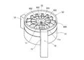
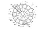
この試薬設置部7は、図6に示すように、試薬収容具300を円環状に並べて保持する円筒形状の試薬保持部50と、試薬保持部50に開閉可能に取り付けられる蓋部60と、円筒形状の試薬保持部50の側面(外壁部51)に取り付けられる昇降部70とを含んでいる。また、試薬設置部7の底部にはペルチエ素子(図示せず)が取り付けられており、試薬設置部7の内部は約15℃に保たれている。 As shown in FIG. 6, the
試薬保持部50は、試薬保持部20と同様に構成されており、図7および図8に示すように、円筒状の外壁部51と、中心に設けられる回転可能な回転軸52と、回転軸52を回転させるためのステッピングモータ53と、ステッピングモータ53の駆動力を回転軸52に伝達するためのベルト54(図8参照)とを含んでいる。外壁部51の内面には全面に渡って断熱材(図示せず)が取り付けられており、試薬保持部50内部の温度を低温(約15℃)に保っている。また、ステッピングモータ53の駆動力は、図8に示すように、ステッピングモータ53により回転するプーリ53aと、回転軸52に同軸上に固定されるプーリ52aとにより、ベルト54を介して回転軸52に伝達されるように構成されている。 The
また、回転軸52には、複数の試薬収容具300を円環状に保持するためのラック600が固定的に取り付けられる。ラック600に試薬収容具300を保持させた状態で回転軸52を回転させることにより、試薬収容具300が保持されたラック600が回転されるので、吸引する試薬を保持する試薬収容具300を後述する蓋部60の孔60bの下方に移動させることが可能である。このラック600は、図9に示すように、ラック600の中心に設けられ、回転軸52が挿入される挿入部601と、挿入部601を中心に円環状に形成され、試薬収容具300を保持するための複数の保持部602と、挿入部601の上方に突出するように設けられた原点検知片603とを含む。保持部602は、仕切板602aと支持部602bとにより構成されている。仕切板602aは、挿入部601から半径方向に放射状に延びるように所定の角度間隔で複数設けられている。支持部602bは、仕切板602aの互いに対向する部分の下部および挿入部501の下部に、内側に突出するように設けられている。各試薬収容具300は、一対の仕切板602aにより挟まれる空間に支持部602bにより底部324(図16参照)の周縁部が支持されるように配置される。また、保持部602の上部、下部および半径方向の外側部を開放端とすることにより、試薬収容具300を昇降させるための昇降部70の載置部71が昇降可能に構成されている。 A
また、本実施形態では、図8に示すように、ステッピングモータ53の駆動により回転軸52が矢印A方向および矢印B方向に往復回転可能に構成されている。すなわち、試薬設置部7に設置されるR2試薬(磁性粒子)を攪拌するために、R2試薬を収容する試薬容器310(試薬収容具300)を保持するラック600を矢印A方向および矢印B方向に往復回転させることによりR2試薬を攪拌して、一般的な粒子と比較して重量の大きい粒子であるR2試薬(磁性粒子)が沈殿するのを抑制している。具体的には、ラック600は、1回転/4秒の速度で角度α(約27度)の角度範囲で往復回転される。すなわち、角度α(約27度)の角度範囲で0.3秒毎に回転方向が逆転するように構成されている。なお、攪拌時の矢印A方向への回転角度および矢印B方向への回転角度は、実質的に等しく設定されている。また、矢印A方向への回転速度および矢印B方向への回転速度も、実質的に等しく設定されている。また、ラック600は、試薬の吸引動作時および試薬収容具300の交換時(追加、取出時)以外は、常に往復回転されることにより、試薬が攪拌されるように構成されている。また、免疫分析装置1の待機時(分析の指示待ちの状態であり、検体の測定動作が行われていない状態)においても、ラック600が往復回転されるように構成されている。 Further, in the present embodiment, as shown in FIG. 8, the
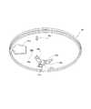
また、蓋部60は、図6に示すように、試薬保持部50にヒンジ部60aを介して開閉可能に取り付けられている。この蓋部60は、試薬設置部7内の温度が低温(15℃)に保たれるように外気を遮断するとともに、試薬設置部7内の試薬を外部から吸引可能で、かつ、試薬収容具300を試薬設置部7内に出し入れ可能なように構成されている。具体的には、蓋部60は、図10および図11に示すように、試薬収容具300の試薬容器310から試薬を吸引する際に試薬分注アーム9のピペット9eが挿入される孔60bと、試薬収容具300を試薬設置部7から昇降部70によって出し入れするための入出孔60cとを含んでいる。また、蓋部60は、孔60bの下方に配置された試薬収容具300のスライド蓋370を開閉可能な開閉部材61と、開閉部材61をスライド可能に支持する直動ガイド62と、開閉部材61を往復駆動するステッピングモータ63とを含んでいる。また、蓋部60には、試薬収容具300がラック600の保持部602に保持されているか否かを検知するための反射型のセンサ60dと、ラック600の原点位置を検知するための透過型の原点検知センサ60eと、開閉部材61の原点位置を検知するための透過形のセンサ60fとが設けられている。センサ60dは、蓋部60の裏面側に向かって光を照射可能なように蓋部60の表面側に配置されており、原点検知センサ60eは、蓋部60の裏面側に配置されている。また、透過形センサ60fは、蓋部60の表面側に配置されている。 Moreover, the
また、図11に示すように、開閉部材61は、開閉部材31と同様に二股の係合片61aを有する。また、試薬収容具300がスライド蓋370が閉まった状態で孔60bの下方に配置された場合には、試薬収容具300のスライド蓋370の係合片373(図12参照)が開閉部材61の二股の係合片61aの間に位置するように構成されている。また、蓋部60の裏面の孔60bの近傍には一対のガイド片60gが取り付けられている。この一対のガイド片60gは、試薬収容具300のスライド蓋370が開いた状態で孔60bの下方に配置された場合に、スライド蓋370の係合片373に当接してガイドすることにより、スライド蓋370の係合片373を開閉部材61の二股の係合片61aの間に位置させる機能を有する。 As shown in FIG. 11, the opening / closing
また、反射型のセンサ60dは、ラック600の保持部602に試薬収容具300が保持されているか否かを検出するように構成されている。また、透過型の原点検知センサ30eは、ラック600に設けられた原点検知片603を検知することにより、回転するラック600の原点位置を検知する機能を有する。 The
昇降部70は、図7および図8に示すように、試薬設置部7内に試薬収容具300を出し入れするために設けられている。昇降部70は、試薬収容具300が載置される載置部71と、載置部71を支持するアーム72と、アーム72を上下方向にスライドさせる駆動部73とを含んでいる。載置部71には、試薬収容具300の試薬容器保持部320の底部324に設けられたリブ325と係合可能な十字形状の溝71aが設けられている。また、アーム72は、外壁部51に設けられた上下方向に延びる孔(図示せず)を介して、試薬保持部50の外部に設けられた駆動部73の駆動力により載置部71を上下方向に移動させる機能を有する。昇降部70は、載置部71に試薬収容具300を載置した状態で載置部71を下降させることにより、試薬収容具300をラック600に保持させることが可能である。また、ラック600に保持された試薬収容具300の下方から上方に載置部71を移動させることにより、ラック600に保持された試薬収容具300を持ち上げて、蓋部60の入出孔60cから試薬収容具300を取り出すことが可能なように構成されている。 As shown in FIGS. 7 and 8, the elevating
なお、試薬設置部6は、試薬保持部6に保持される試薬収容具200がR1試薬を収容する試薬容器210およびR2試薬を収容する試薬容器220(図20参照)の2つの試薬容器を含むことに対応して、試薬収容具200の2つのスライド蓋280および290(図20参照)を開閉するために蓋部30に開閉機構が2つ設けられていることなどを除き、試薬設置部7と同様の構成を有するので詳細な説明を省略する。 The reagent installing unit 6 includes two reagent containers: a
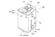
ここで、本実施形態による試薬収容具300について詳細に説明する。本実施形態による試薬収容具300は、図12〜図19に示すように、R2試薬が収容される試薬容器310と、試薬容器310を保持する試薬容器保持部320と、試薬容器310を覆うように試薬容器保持部320に取り付けられるケース330とを備えている。 Here, the
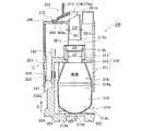
試薬容器310は、高密度ポリスチレンにより形成される。また、図15に示すように、試薬容器310は、使用開始前(ユーザへの供給時)では、開口312aにアルミシール310aが貼付されることにより密閉され、試薬容器310に収容された試薬の劣化および漏れなどが抑制されている。この試薬容器310は、試薬が収容される胴部311と、試薬を吸引するための開口312aを有する頭部312と、胴部311と頭部312とを連結する首部313とを含んでいる。頭部312は円筒状に形成されており、頭部312の内径d3(図19参照)は、後述する筒部361の外径D3(図19参照)と実質的に等しく形成されている。また、図19に示すように、頭部312の開口312a近傍には、後述するように、開口312aにシールされているアルミシール310aが突部361cによって突き破られた時にアルミシール310aが収納されるシール収容部312bが設けられている。具体的には、頭部312の開口312a近傍の内径d4は、頭部312の他の部分の内径d3よりも大きく形成されており、この内径d4の部分(シール収容部312b)に破られたアルミシール310aが収容されるように構成されている。また、首部313は、頭部312および胴部311に対してくびれるように形成されている。 The
また、試薬容器保持部320は、図14および図15に示すように、試薬容器310を着脱可能に保持することが可能であり、試薬容器310の首部313と係合する係合部321と、ケース330に対して試薬容器保持部320が下方に移動するのを抑制するための一対のフック部322と、ケース330に対して試薬容器保持部320が上方に移動するのを抑制するための係合部323と、底部324に設けられ、昇降部材70の載置部71と係合するためのリブ325とを含んでいる。 As shown in FIGS. 14 and 15, the reagent
係合部321は、試薬容器310の首部313と係合することにより、試薬容器310を試薬容器保持部320に保持するように構成されている。また、一対のフック部322は、後述するケース330に設けられた一対の孔341および孔342と係合することにより、試薬容器保持部320がケース330から外れることを抑制する機能を有する。また、係合部323は、後述するケース330に設けられた孔343と係合することにより、試薬容器保持部320がケース330に対して、所定の位置から上方に移動するのを抑制する機能を有する。また、図16に示すように、底部324に設けられたリブ325は十字形状に設けられている。 The
また、図12および図13に示すように、ケース330は、試薬容器310および試薬容器保持部320の側面を覆うケース本体340と、ケース本体340に固定的に取り付けられる上蓋部350とからなる。また、ケース330は、ケース本体340と上蓋部350とが固定された状態で、下端330aが開放された箱状に形成されている。ケース本体340には、試薬容器保持部320の一対のフック部322と係合する一対の孔341と、一対の孔341の上方に所定の間隔を隔てて設けられた一対の孔342と、試薬容器保持部320の係合部323と係合する孔343と、上下方向に延びるように形成されたスリット344(図13参照)が設けられている。本実施形態では、試薬収容具300は、スリット344を介して、試薬容器310に収容された試薬の量を視認可能に構成されている。 As shown in FIGS. 12 and 13, the
また、図17〜図19に示すように、上蓋部350は、上蓋本体360と、上蓋本体360にスライド可能に取り付けられるスライド蓋370とを含んでいる。また、上蓋本体360は、試薬容器310の開口312aに挿入される筒部361と、蓋部60に設けられた反射型のセンサ60eが照射する光を反射するための反射部362と、スライド蓋370がスライドするためのスライドレール363と、スライド蓋370の位置をそれぞれ規制するための凹部364とを有する。 Moreover, as shown in FIGS. 17-19, the
また、図19に示すように、筒部361は、上側の開口端面361aが水平面から所定の角度傾斜した傾斜面となるように形成されている。また、下側の開口端面361bは、水平面となるように形成されている。また、下側の開口端面361bには、下方へ突出する尖った形状を有する突部361cが設けられている。この突部361cにより開口312aに貼付されたアルミシール310aを突き破ることが可能である。 Moreover, as shown in FIG. 19, the
また、凹部364は、スライド蓋370の突出部372と当接することによりスライド蓋370の移動を規制するとともに、スライド蓋370が上蓋本体360から脱落することを抑制する機能を有する。また、凹部364には、スライド蓋370が筒部361の上側の開口端面361aを閉じる位置にある時に、スライド蓋370の突出部372と係合する凸状のリブ364aが設けられている。これにより、スライド蓋370が筒部361を密閉した状態でスライド蓋370を固定することが可能である。 In addition, the
また、図19に示すように、スライド蓋370は、スライドレール363に係合する係合部371と、上蓋本体360の凹部364に嵌め込まれる突出部372と、蓋部60の開閉部材61と係合する係合片373と、所定の角度傾斜する傾斜面となるように形成された当接部374とを含んでいる。当接部374には、スライド蓋370が筒部361を密閉する時に筒部361の上側の開口端面361aと密着する板状のシリコンシート374aが取り付けられている。 Further, as shown in FIG. 19, the
また、図19に示すように、試薬容器310は、滑らかな凹面状に形成された底部314と、円筒状に形成された中部315と、中部315の上端から上方に向かって水平断面の断面積が徐々に狭くなるように形成されたテーパ−形状部316とを含んでいる。底部314の水平断面は円形状に形成されており、先端314aを含む内部形状が実質的に球面状に形成されている。また、底部314の内面には、内側に突出する段差部314bが設けられている。また、R2試薬は、液面がテーパ−形状部316の下端316aよりも低くなるように試薬容器310に収容される。 Further, as shown in FIG. 19, the
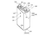
ここで、本実施形態による試薬収容具200について詳細に説明する。本実施形態による試薬収容具200は、図20〜図29に示すように、R1試薬が収容される試薬容器210と、R3試薬が収容される試薬容器220と、試薬容器210および試薬容器220を保持する試薬容器保持部230と、試薬容器210および試薬容器220を覆うように試薬容器保持部230に取り付けられるケース240とを備えている。 Here, the
試薬容器210および試薬容器220は、高密度ポリスチレンにより形成される。また、図23に示すように、試薬容器210および試薬容器220は、それぞれ、使用開始前(ユーザへの供給時)では、後述する開口212aおよび開口222aにアルミシール210aおよび220aが貼付されることにより密閉され、試薬容器210および試薬容器220に収容された試薬の劣化および漏れなどが抑制されている。また、試薬容器210は、試薬が収容される胴部211と、試薬を吸引するための開口212aを有する頭部212と、胴部211と頭部212とを連結する首部213とを含んでいる。胴部211の内面には、図25および図26に示すように、上下方向に延びるように内側に突出する凸部211a(図25参照)および水平方向に延びるように内側に突出する凸部211b(図26参照)が設けられている。また、頭部212は、円筒状に形成されており、頭部212の内径d1(図26参照)は、後述する筒部271の外径D1(図29参照)と実質的に等しく形成されている。また、図26に示すように、頭部212の開口212a近傍には、後述するように、開口212aを密封しているアルミシール210aが突部271cによって突き破られた時にアルミシール210aが収納されるシール収容部212bが設けられている。具体的には、頭部212の開口212a近傍の内径d2は、頭部212の他の部分の内径d1よりも大きく形成されており、この内径d2の部分(シール収容部212b)に破られたアルミシール210aが収容されるように構成されている。また、首部213は、頭部212および胴部211に対してくびれるように形成されている。また、図23に示すように、試薬容器220も試薬容器210と同様に、胴部221、頭部222および首部223を備え、開口222a、上下方向に延びるように内側に突出する凸部221a、水平方向に延びるように内側に突出する凸部221bおよびシール収容部(図示せず)を含んでいる。また、試薬容器220の頭部222の内径は、後述する筒部272の外径D2(図29参照)と実質的に等しく形成されている。 The
また、試薬容器保持部230は、試薬容器210および試薬容器220を着脱可能に保持することが可能であり、図22および図23に示すように、試薬容器210の首部213と係合する係合部231と、試薬容器220の首部223と係合する係合部232と、ケース240に対して試薬容器保持部230が下方に移動するのを抑制するための一対のフック部233と、ケース240に対して試薬容器保持部230が上方に移動するのを抑制するための係合部234と、底部235に設けられ、昇降部40の載置部41の溝41aと係合するためのリブ236と、後述するケース本体250のスリット254に対応した位置に設けられるスリット237とを含んでいる。 The reagent
係合部231および係合部232は、それぞれ、試薬容器210および試薬容器220の首部213および223と係合可能なように、首部213、223の直径とそれぞれ実質的に等しい幅の凹部が形成されている。首部213、223をそれぞれ係合部231、232に係合させることで、試薬容器210および試薬容器220が試薬容器保持部230に保持される。また、一対のフック部233は、後述するケース240に設けられた一対の孔251および孔252と係合することにより、試薬容器保持部230がケース240から外れることを抑制する機能を有する。また、係合部234は、後述するケース240に設けられた孔253と係合することにより、試薬容器保持部230がケース240に対して、所定の位置から上方に移動するのを抑制する機能を有する。また、図24に示すように、底部235に設けられたリブ236は十字形状に設けられている。 The engaging
また、ケース240は、図20および図21に示すように、試薬容器210、試薬容器220および試薬容器保持部230の側面を覆うケース本体250と、ケース本体250に固定的に取り付けられる上蓋部260とからなる。また、ケース240は、ケース本体250と上蓋部260とが固定された状態で、下端240aが開放された箱状に形成されている。ケース本体250には、試薬容器保持部230の一対のフック部233と係合する一対の孔251と、一対の孔251の上方に所定の間隔を隔てて設けられた一対の孔252と、試薬容器保持部230の係合部234と係合する孔253と、上下方向に延びるように形成されたスリット254および255とが設けられている。本実施形態では、試薬収容具200は、スリット254および試薬容器保持部230のスリット237を介して、試薬容器210に収容されている試薬の量を視認可能に構成されている。また、試薬収容具200は、スリット255を介して、試薬容器220に収容されている試薬の量を視認可能に構成されている。 20 and 21, the
また、上蓋部260は、図27〜図29に示すように、上蓋本体270と、上蓋本体270にスライド可能に取り付けられるスライド蓋280およびスライド蓋290とを含んでいる。また、上蓋本体270は、試薬容器210の開口212aおよび試薬容器220の開口222aにそれぞれ挿入される筒部271および筒部272と、蓋部30に設けられた反射型のセンサ30fが照射する光を反射するための反射部273と、スライド蓋280およびスライド蓋290がスライドするためのスライドレール274と、スライド蓋280およびスライド蓋290の位置をそれぞれ規制するための凹部275および凹部276とを有する。 As shown in FIGS. 27 to 29, the
筒部271は、図28および図29に示すように、上側の開口端面271aが水平面から所定の角度傾斜した傾斜面となるように形成されている。また、下側の開口端面271bは、水平面となるように形成されている。また、下側の開口端面271bには、下方に突出する尖った形状を有する突部271cが設けられている。この突部271cにより試薬容器210の開口212aに貼付されたアルミシール210aを突き破ることが可能である。筒部272も筒部271と同様に、上側の開口端面272aと、下側の開口端面272bと、下側の開口端面272bから下方に突出する尖った形状を有する突部272cを含んでいる。 As shown in FIGS. 28 and 29, the
また、凹部275は、後述するスライド蓋280の突出部282と当接することによりスライド蓋280の移動を規制するとともに、スライド蓋280が上蓋本体270から脱落することを抑制する機能を有する。また、凹部275には、スライド蓋280が筒部271の上側の開口端面271aを閉じる位置にある時に、スライド蓋280の突出部282と係合する凸状のリブ275aが設けられている。これにより、スライド蓋280が筒部282を密閉した状態でスライド蓋280を固定することが可能である。また、凹部276も凹部275と同様に、スライド蓋290が筒部272の上側の開口端面272aを閉じる位置にある時に、スライド蓋290の突出部282と係合する凸状のリブ276aが設けられている。 Further, the
また、スライド蓋280は、上蓋本体270に対してスライドすることにより筒部271を開閉するように構成されている。このスライド蓋280は、スライドレール274に係合する係合部281と、上蓋本体270の凹部275に嵌め込まれる突出部282と、蓋部30の開閉部材31と係合する係合片283と、所定の角度傾斜する傾斜面となるように形成された当接部284とを含んでいる。当接部284には、スライド蓋280が筒部を密閉する時に筒部の上側の開口端面271aと密着する板状のシリコンシート284aが取り付けられている。また、スライド蓋290は、スライド蓋280と同様に、上蓋本体270に対してスライドすることにより筒部272を開閉するように構成されている。また、スライド蓋290は、図29に示すように、スライドレール274に係合する係合部291(図27参照)と、突出部292と、蓋部30の開閉部材34と係合する係合片293と、シリコンシート294aが取り付けられた当接部294とを含んでいる。 The
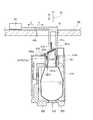
図19および図30は、それぞれ、試薬収容具の未使用状態を示す断面図および斜視図である。図31は、試薬収容具の使用状態を示す断面図である。次に、図19、図30および図31を参照して、本実施形態による試薬収容具300の使用方法を説明する。 19 and 30 are a cross-sectional view and a perspective view, respectively, showing an unused state of the reagent container. FIG. 31 is a cross-sectional view showing a usage state of the reagent container. Next, with reference to FIG. 19, FIG. 30, and FIG. 31, a method of using the
本実施形態による試薬収容具300は、図19および図30に示す状態でユーザに供給される。すなわち、ユーザに供給される際には、ケース本体340の孔343と試薬容器保持部320の係合部323とが係合するとともに、ケース本体340の孔341と試薬容器保持部320のフック部322とが係合している。これにより、試薬容器310を保持する試薬容器保持部320は、ケース330に対して所定の位置(以下、未使用位置)に保持されている。この状態においては、上蓋本体360の筒部361の下側の開口端面361bから突出する突部361cと、試薬容器310の開口312aに貼付されたアルミシール310aとは離間している。このように、ユーザへの供給時には、試薬容器310は開口312aがアルミシール310aにより密閉されており、試薬の漏れや劣化が抑制されている。 The
次に、試薬収容具300を使用する場合には、ユーザは、矢印C方向に試薬容器保持部320の係合部323を押圧することにより、試薬容器保持部320の係合部323とケース本体340の孔343との係合を解除する。これにより、試薬容器保持部320をケース330に対して上方に移動させることが可能となる。そして、試薬容器保持部320をケース330に対して未使用位置から上方(矢印D方向)に移動させる。そして、試薬容器保持部をケース330に対して上方に移動させる過程において、上蓋本体360の筒部361から下方に突出する突部361cによって、試薬容器310の開口312aに貼付されたアルミシール310aが突き破られる。そして、さらに試薬容器保持部320を上方に移動させると、筒部361が試薬容器310の頭部312に挿入される。これにより、試薬分注アーム9のピペット9eが上蓋本体360の筒部361を介して試薬容器310の試薬を吸引することが可能となる。また、この時、突部361cによって突き破られたアルミシール310aは、試薬容器310の開口312a近傍に設けられたシール収容部312bに収容される。そして、試薬容器保持部320をさらに上方に移動させると、ケース本体340の孔342と、試薬容器保持部320のフック部322とが係合するとともに、試薬容器保持部320の底部324とケース330の下端330aとが当接して、ケース330の開放端が閉じられる。これにより、図31に示すように、試薬容器保持部320は、ケース330に対して、試薬収容具300を分析に用いることが可能な位置(使用位置)に保持される。このように、本実施形態では、試薬容器保持部320をケース330に対して使用位置に位置させて試薬容器310を開封することにより、試薬収容具300が分析に用いられる。 Next, when the
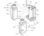
なお、試薬収容具200も、試薬収容具300の場合と同様の手順により試薬容器210および試薬容器220を開封した状態で分析に使用される。図32および図33は、それぞれ、試薬収容具の未使用状態を示す斜視図および断面図である。図34は、試薬収容具の使用状態を示す断面図である。次に、図32〜図34を参照して、本実施形態による試薬収容具200の使用方法を説明する。 The
試薬容器保持部200は、図32および図33に示すような状態でユーザに供給される。すなわち、ケース240に対して、試薬容器保持部230の係合部234とケース本体250の孔253とが係合するとともに試薬容器保持部230のフック部233とケース本体250の孔251とが係合している未使用位置に保持されている。そして、試薬容器保持部230の係合部234とケース本体250の孔253との係合を解除して試薬容器保持部230をケース240に対して上方に移動させると、試薬容器210の開口212aおよび試薬容器220の開口222aにそれぞれ貼付されたアルミシール210aおよび220aが上蓋本体270の突部271cおよび突部272cによって突き破られる。そして、突き破られたアルミシール210aおよび220aは、試薬容器210のシール収容部212bおよび試薬容器220のシール収容部(図示せず)に収容される。そして、さらに試薬容器保持部230を上方に移動させると、図34に示すように、試薬容器保持部230のフック部233とケース本体250の孔252とが係合するとともに、試薬容器保持部230の底部235とケース240の下端240aとが当接して、ケース240の下端240aが閉じられる。これにより、試薬容器保持部230は、ケース240に対して、試薬分注アーム8のピペット8eおよび試薬分注アーム10のピペット10eが、それぞれ、上蓋本体270の筒部271および筒部272を介して試薬容器210および試薬容器220の試薬を吸引することが可能な位置(使用位置)に保持される。 The reagent
図35および図36は、試薬収容具と、蓋部の孔と、試薬を吸引するピペットとを示す断面図である。次に、図1、図8、図11、図35および図36を参照して、本実施形態による試薬収容具300から試薬分注アーム9のピペット9eにより試薬を吸引する吸引動作を説明する。 35 and 36 are cross-sectional views showing the reagent container, the hole of the lid, and the pipette that sucks the reagent. Next, with reference to FIG. 1, FIG. 8, FIG. 11, FIG. 35 and FIG. 36, a suction operation for sucking a reagent from the
まず、試薬保持部50の回転軸52(図8参照)が試薬収容具300を保持するラック600を回転させることにより、吸引対象の試薬を収容した試薬容器310を含む試薬収容具300が蓋部60の孔60bの下方に移動される。試薬収容具300が蓋部60の孔60bの下方に移動する際、試薬収容具300のスライド蓋370が閉まっている場合には、図35に示すように、スライド蓋370の係合片373が蓋部60の開閉部材61の二股の係合部61aの間に配置される。また、試薬収容具300が蓋部60の孔60bの下方に移動する際、試薬収容具300のスライド蓋370が開いている場合には、スライド蓋370の係合片373は、蓋部60の孔60bの近傍に配置されたガイド片60g(図11参照)によりガイドされて開閉部材61の二股の係合部61aの間に配置される。 First, the rotation axis 52 (see FIG. 8) of the
この状態で、ステッピングモータ63により開閉部材61が矢印E方向にスライドされることにより、図36に示すように、スライド蓋370の係合片373が二股の係合部61aとともに矢印E方向にスライドされてスライド蓋370が開状態となる。これにより、蓋部60の孔60bのうち、開閉部材61がスライドすることによって空いた領域と、筒部361とを介して試薬分注アーム9のピペット9eを試薬容器310の内部に挿入することが可能となる。また、ピペット9eは、モータ9aおよび駆動伝達部9bによる回動により蓋部60の孔60bの上方に移動されており、スライド蓋370の開状態でピペット9eが下降することによりピペット9eが孔60bと筒部361とを介して試薬容器310の内部に挿入されて、試薬が吸引される。なお、試薬容器310を密閉していたアルミシール310aはシール収容部312bに収容されているため、ピペット9eが試薬容器310の内部に挿入される際、突き破られたアルミシール310aがピペット9eに接触することが抑制されている。 In this state, when the opening / closing
そして、試薬を吸引したピペット9eは、モータ9aおよび駆動伝達部9bにより上昇するとともに回動されて、1次反応部11(図1参照)の上方に移動される。そして、1次反応部11のキュベット150に試薬容器310から吸引した試薬が分注される。 And the
また、試薬の吸引が終了した後、回動部材61がステッピングモータ63により矢印F方向に移動されることによって、スライド蓋370の係合片373が二股の係合部61aとともに矢印F方向にスライドされる。これにより、筒部361の上側の開口端面361aとスライド蓋370の当接部374に取り付けられたシリコンシート374aとが密着して、試薬が密閉状態となる。また、筒部361の上側の開口端面361aとシリコンシート374aとが密着した状態で、スライド蓋370の突出部372と上蓋本体360の凹部364に設けられたリブ364aとが係合して、スライド蓋370が固定される。これにより、ラック600が回転されて試薬収容具300が移動される際などにも、試薬の密閉状態が保持される。 Further, after the reagent is aspirated, the rotating
なお、試薬収容具200の試薬容器210から試薬を試薬分注アーム8のピペット8aにより吸引する場合、または、試薬収容具200の試薬容器220から試薬を試薬分注アーム10のピペット10eにより吸引する場合も、上記した試薬収容具300から試薬分注アーム9のピペット9eにより吸引する場合と同様の流れによって試薬の吸引が行われる。 When the reagent is aspirated from the
本実施形態では、上記のように、筒部361と、試薬容器保持部320がケース330に対して使用位置に保持されたときに突部361cによってアルミシール310aが突き破られた開口312aとを介して、試薬容器310内の試薬を吸引することができる。これにより、ユーザがアルミシール310aを剥がすなどの作業を行う必要がないため、試薬容器310に収容されている試薬を汚染したり、または、ユーザに試薬が付着するという汚染事故の発生を抑制しながら試薬の吸引を行うことができる。 In the present embodiment, as described above, the
また、本実施形態では、上記のように、試薬容器310に、突部361cによって突き破られたアルミシール310aが収容されるシール収容部312bを設けることによって、突き破られたアルミシール310aをピペット9eの通過経路に残らないようにシール収容部312bに収容することができるので、突き破られたアルミシール310aの影響を受けることなく、開口312aおよび筒部361を介して試薬を吸引することができる。 In the present embodiment, as described above, the
また、本実施形態では、上記のように、試薬容器保持部320を、ケース330に対して、突部361cがアルミシール310aを突き破って試薬容器310の開口312a内に位置する使用位置と、突部361cがアルミシール310aから離間している未使用位置とに保持可能に構成することによって、試薬収容具300を使用する前には、試薬容器保持部320を突部361cがアルミシール310aから離間している未使用位置に保持し、試薬収容具300を使用する際に、試薬容器保持部320を突部361cがアルミシール310aを突き破って試薬容器310の開口312a内に位置する使用位置に保持することができる。これにより、たとえば、試薬容器保持部320が未使用位置に保持された状態で、試薬収容具300の保存、運搬などを行い、試薬容器保持部320を使用位置に保持して試薬収容具300を使用(試薬を吸引)することができるので、使用者の利便性を増すことができる。 Further, in the present embodiment, as described above, the reagent
また、本実施形態では、上記のように、ケース330の上蓋部350に、筒部361の上側の開口端面361aを開閉可能なスライド蓋370を設けることによって、アルミシール310aが突部361cにより突き破られた後においても、スライド蓋370により筒部361の上側の開口端面361aを開閉することができる。これにより、試薬の吸引時にはスライド蓋370を開いて試薬を吸引し、試薬の非使用時には、スライド蓋370を閉じて試薬を密閉した状態で保存することができる。 Further, in the present embodiment, as described above, the
また、本実施形態では、上記のように、スライド蓋370をスライドすることにより筒部361の上側の開口端面361aを開閉することによって、スライド蓋370をスライドさせることにより、容易に筒部361の上側の開口端面361aを開閉することができる。 In the present embodiment, as described above, by sliding the
また、本実施形態では、上記のように、スライド蓋370に筒部361の上側の開口端面361aをシールするためのシリコンシート375を取り付けることによって、スライド蓋370を閉じて、シリコンシート375を筒部361の上側の開口端面361aに密着させることにより、容易に、試薬を密閉状態にすることができる。 In the present embodiment, as described above, by attaching the silicon sheet 375 for sealing the opening
また、本実施形態では、上記のように、試薬容器210に、内面側に突出するとともに、上下方向および水平方向に延びるように凸部211aおよび211bを設けることによって、試薬収容具200が試薬保持部20内で回転移動されるのに伴って試薬容器210内で試薬が移動する際、移動しようとする試薬が試薬容器210の内面側に設けられた凸部211aおよび211bに当たることにより試薬の移動を抑制することができる。これにより、試薬が泡立つのを抑制することができる。 In the present embodiment, as described above, the
また、本実施形態では、上記のように、突部361cによってアルミシール310aが突き破られて開封されたとき、開口312aに筒部361が嵌入され、筒部361を介して試薬容器310の内部へ試薬を吸引するためのピペット9eを挿入することによって、突部361cによってアルミシール310aを突き破った後、開口312aに嵌入された筒部361を介して、容易に、試薬容器310の内部にピペット9eを挿入することができる。 In the present embodiment, as described above, when the
また、本実施形態では、上記のように、突部361cによってアルミシール310aが突き破られて開封されたとき、ケース330の下端330aが試薬容器保持部320の底部324によって閉じられるように構成することによって、突部361cによってアルミシール310aが突き破られた開封状態において、ケース330と試薬容器保持部320とが一体となるため、試薬収容具300を容易に扱うことができる。 In the present embodiment, as described above, the
また、本実施形態では、上記のように、箱状のケース330のケース本体340に試薬容器310内の試薬を視認可能なスリット344を設けることによって、ユーザは、スリット344を介して試薬容器310内の試薬の量を確認することができる。 In the present embodiment, as described above, the case
また、本実施形態では、上記のように、試薬容器保持部320の底部324に、昇降部70の載置部71の溝71aに係合するためのリブ325を設けることによって、リブ325を溝71aに係合させることにより、容易に、昇降部70によって試薬収容具300を昇降させることができる。 In the present embodiment, as described above, the
なお、今回開示された実施形態は、すべての点で例示であって制限的なものではないと考えられるべきである。本発明の範囲は、上記した実施形態の説明ではなく特許請求の範囲によって示され、さらに特許請求の範囲と均等の意味および範囲内でのすべての変更が含まれる。 The embodiment disclosed this time should be considered as illustrative in all points and not restrictive. The scope of the present invention is shown not by the above description of the embodiments but by the scope of claims for patent, and further includes all modifications within the meaning and scope equivalent to the scope of claims for patent.
たとえば、上記実施形態では、試薬収容具200および300を免疫分析装置1に用いた例を示したが、本発明はこれに限らず、試薬が用いられる分析装置であれば他の分析装置に用いてもよい。 For example, in the above-described embodiment, the example in which the
また、上記実施形態では、2つの試薬容器210および220を保持するように試薬収容具200を構成し、1つの試薬容器310を保持するように試薬収容具300を構成した例を示したが、本発明はこれに限らず、試薬収容具に3つ以上の試薬容器を保持するように構成してもよい。 In the above embodiment, the
また、上記実施形態では、上蓋本体360の筒部361の下側の開口端面361bの切り口を水平面となるように形成した例を示したが、本発明はこれに限らず、図37に示す変形例による上蓋本体700のように、筒部701の下側の開口端面701aの切り口を所定の角度傾斜する傾斜面となるように形成してもよい。 Moreover, in the said embodiment, although the example which formed the cut surface of the lower opening
8e、9e、10e ピペット
41、71 載置部
200、300 試薬収容具
210、220、310 試薬容器
210a、220a、310a アルミシール(シール部材)
211a、211b、221a、221b リブ(凸部)
212a、222a、312a 開口
212b、312b シール収容部
231、232、321 係合部
235、324 底部(底部)
240、330 ケース(開封部)
240a、330a 下端(開放端)
254、255、344 スリット(スリット部)
271、272、361 筒部(吸引孔)
271b、272b、361b 開口端面(下部)
271c、272c、361c 突部
280、290、370 スライド蓋(蓋部)
284a、294a、374a シリコンシート(シート状部材)8e, 9e,
210, 220, 310
211a, 211b, 221a, 221b Rib (convex part)
212a, 222a, 312a
240, 330 Case (opening part)
240a, 330a Lower end (open end)
254, 255, 344 Slit (slit part)
271, 272, 361 Tube (suction hole)
271b, 272b, 361b Open end face (lower part)
271c, 272c,
284a, 294a, 374a Silicon sheet (sheet-like member)
Claims (15)
Translated fromJapanese内部に試薬が収容された状態で開口がシール部材により封止された試薬容器、前記試薬容器を保持する試薬容器保持部、および第1係合部を有する試薬収容部と、
前記吸引管が挿入される吸引孔、前記試薬容器内に進入することにより前記シール部材を突き破る突部、および前記第1係合部と係合可能な第2係合部を有し、一端が開放された箱状に形成されており、その開放端から前記試薬保持部に保持されている前記試薬容器を収容可能に形成されている開封部と、を備え、
前記開封部の開放端から前記試薬容器保持部に保持されている試薬容器を収容させることにより、前記突部が前記シール部材を突き破るとともに、前記第1係合部と前記第2係合部が係合して前記開封部と前記試薬収容部が一体になり、前記吸引孔と、前記突部によって前記シール部材が突き破られた前記開口とを介して、前記吸引管によって前記試薬容器内の試薬を吸引することが可能に構成されている試薬収容具。A reagent container for use in an automatic analyzer that includes a suction tube for sucking a reagent and analyzes a sample using the reagent sucked by the suction tube,
A reagent storage section thatYusukeapertures in a state where the reagentinside is accommodatedsealed reagent container by the sealingmember, the reagent container holder for holding the reagent container, and a first engagement portion,
A suction hole into which the suction tube is inserted, a protrusionthat breaks through the seal member by entering the reagent container, and a second engagement portion thatcan be engaged with the first engagement portion, and hasone end is formed in the opened box shape, provided with a tearing portionwhich is formed to accommodate the reagent container from the open end is held in the reagent holdingportion,
By accommodating the reagent container held in the reagent container holding part from the open end of the opening part, the protrusion breaks through the seal member, and the first engagement part and the second engagement part are The unsealing part and the reagent storage part are integrated with each other, and thesuction pipe and the opening in which the seal member is pierced by the protrusion are inserted into the reagentcontainerby the suction pipe.reagents containing assemblythat is configured to be capable to suck a reagent.
前記開封部は、前記開閉機構によって開閉されることで前記吸引孔を開放および閉鎖可能な蓋部をさらに含み、
前記開閉機構によって蓋部が開けられ開放された吸引孔と、前記シール部材が突き破られて開放された開口とを介して、前記吸引管によって前記試薬容器内の試薬を吸引することが可能に構成されている請求項1〜3のいずれか1項に記載の試薬収容具。A reagent container used in the automatic analyzer further comprising an opening and closing mechanism,
The opening portion isfurtherseen includingopening and closable lid portion the suction holeby being opened and closed by the opening and closingmechanism,
The reagent in the reagent container can be sucked by the suction tube through the suction hole opened and opened by the opening / closing mechanism and the opening opened by the seal member being pierced. The reagent container according to any one of claims 1 to 3,which is configured .
前記蓋部は、前記スライドレール上を直線的にスライド移動することにより前記吸引孔を開放および閉鎖し、
前記開閉機構は、スライドレール上において前記蓋部を所定方向にスライド移動させることにより前記吸引孔を開放および閉鎖するように構成されている請求項4に記載の試薬収容具。The opening portion further includes a slide rail,
The lid,Tozashiopen- and closed the suction holes bylinearlyslidingon the sliderail,
The opening and closing mechanism, a reagent container according to請 Motomeko 4that is configured toopen and close the suction hole by sliding the lid in a predetermined direction on the slide rail.
前記開封部の開放端から前記試薬容器保持部に保持された試薬容器を収容させることにより、前記第1係合部と前記第2係合部が係合するとともに、前記開封部の開放端が前記試薬容器保持部の底部と当接して前記開封部と前記試薬収容部が一体になるよう構成されている請求項1〜6のいずれか1項に記載の試薬収容具。The reagent container holding part includes a bottom part for closing an open end of the opening part,
By accommodating the reagent container held in the reagent container holding part from the open end of the opening part, the first engaging part and the second engaging part are engaged, and the open end of the opening part is The reagent container according to any one of claims 1 to 6,wherein the reagent container is configured such that the unsealing part and the reagent container are integrated with each other in contact with a bottom part of the reagent container holding part .
前記試薬容器保持部は、前記試薬容器の第3係合部に係合することによって前記試薬容器を保持するように構成されている、請求項1〜8のいずれか1項に記載の試薬収容具。The reagent container has athird engaging part for engaging with the reagent container holding part,
The reagent container according toany one of claims 1 to8, wherein the reagent container holding part is configured to hold the reagent container by engaging with athird engaging part of the reagent container. Ingredients.
前記突部は、前記筒部の下部に設けられており、
前記開封部の開放端から前記試薬容器保持部に保持された試薬容器を収容させることにより、前記突部によって前記シール部材が突き破られた前記開口に前記筒部が嵌入され、前記筒部を介して前記試薬容器の内部へ前記吸引管を挿入することが可能に構成されている、請求項1〜9のいずれか1項に記載の試薬収容具。The opening portion includes a cylindrical portion having the suction hole,
The protrusion is provided at a lower portion of the cylindrical portion,
By accommodating the reagent container held in the reagent container holding part from the open end of the opening part, the cylindrical part is fitted into the opening in whichthe seal member is pierced by the protruding part, and the cylindrical part is The reagentcontainer of any one of Claims 1-9 comprised so that the saidsuction tube can be inserted in the inside of the said reagentcontainer via.
前記試薬容器保持部は、その底部に前記搬送機構に係合するための第4係合部をさらに備える請求項1〜12のいずれか1項に記載の試薬収容具。A reagent container used in the automatic analyzer further comprising a transport mechanism for transporting the reagent container,
The reagent containerholder, the reagent container according toany one of claims 1 to12,further comprising afourth engagement portion for engagingsaid transportmechanismat the bottom ofit.
内部に試薬が収容された状態で開口がシール部材により封止された試薬容器と、
第1係合部を有し、前記試薬容器を保持する保持部材と、
前記吸引管が挿入される吸引孔、前記試薬容器内に進入することにより前記シール部材を突き破る突部、および前記第1係合部と係合可能に構成されている第2係合部を有し、一端が開放された箱状に形成されており、その開放端から前記保持部材により保持された前記試薬容器を収容可能に形成されているケースと、を備え、
前記ケースの開放端から前記保持部材に保持された試薬容器を収容させることで、前記突部が前記シール部材を突き破るとともに、前記第1係合部と第2係合部が係合して前記ケースと前記保持部材が一体になり、前記吸引孔と、前記シール部材が突き破られた前記開口とを介して、前記吸引管によって前記試薬容器内の試薬を吸引することが可能に構成されている試薬収容具。A reagent container for use in an automatic analyzer that includes a suction tube for sucking a reagent and analyzes a sample using the reagent sucked by the suction tube,
Asealed reagent container byapertures in a state where the reagentinside is housed a seal member,
A holding memberhaving a first engagement portion and holding the reagent container;
A suction hole into which the suction tube is inserted; a protrusion that breaks through the seal member by entering the reagent container; and a second engagement portion configured to be engageable with the first engagement portion. and one end is formed in the opened box shape, it includesa casefrom the open end and is capable of accommodating formation of the reagent container held by the holdingmember,
Be to accommodate the reagent container held in the holding member from the open end of theprevious SLcase, theprojectionsRutotomoni Tsukiyabusaid sealing member,said second engaging portion and the first engaging portion is engaged Then, the case and the holding member are integrated, and the reagentin the reagent container can be suckedby the suction tube through the suction hole and the opening through which the seal member is broken.reagent-containing assemblythat has been configured.
第1係合部を有し、内部に試薬が収容された状態で開口がシール部材により封止された試薬容器を保持可能に構成された保持部材と、
前記吸引管が挿入される吸引孔、前記試薬容器内に進入することにより前記シール部材を突き破る突部、および前記第1係合部と係合可能に構成されている第2係合部を有し、一端が開放された箱状に形成されており、その開放端から前記保持部材によって保持された前記試薬容器を収容可能に形成されているケースと、を備え、
前記ケースの開放端から前記保持部材に保持された前記試薬容器を収容させることで、前記突部が前記シール部材を突き破るとともに、前記第1係合部と第2係合部が係合して前記ケースと前記保持部材とが一体になり、前記吸引孔と、前記シール部材が突き破られた前記開口とを介して、前記吸引管によって前記試薬容器内の試薬を吸引することが可能に構成されている試薬容器保持具。A reagent container holder for use in an automatic analyzer that includes a suction tube for sucking a reagent and analyzes a sample using the reagent sucked by the suction tube,
Has a first engaging portion, a holdingmember openingiscapable of holdingconstituting asealed reagent container by the sealing memberin a state where the reagent inside is accommodated,
A suction hole into which the suction tube is inserted; a protrusion that breaks through the seal member by entering the reagent container; and a second engagement portion configured to be engageable with the first engagement portion. and one end is formed in the opened box shape, it includesa casefrom the open end and is capable of accommodating formation of the reagent container held by the holdingmember,
Be to accommodate the reagent container from the open end of thecase held by the holding member, theprojectionsRutotomoni Tsukiyabusaid sealing member,said second engaging portion and the first engaging portion is engaged Then, the case and the holding member are integrated, and the reagentin the reagent container can be suckedby the suction tube through the suction hole and the opening through which the seal member is broken.reagents container holderthat is configured to.
Priority Applications (4)
| Application Number | Priority Date | Filing Date | Title |
|---|---|---|---|
| JP2006276464AJP4861787B2 (en) | 2006-10-10 | 2006-10-10 | Reagent container and reagent container holder |
| EP07019707.4AEP1918721B1 (en) | 2006-10-10 | 2007-10-09 | Reagent-containing assembly |
| US11/973,718US7790114B2 (en) | 2006-10-10 | 2007-10-09 | Reagent-containing assembly |
| CN200710162808XACN101161559B (en) | 2006-10-10 | 2007-10-10 | Reagent holding device and reagent container holding device |
Applications Claiming Priority (1)
| Application Number | Priority Date | Filing Date | Title |
|---|---|---|---|
| JP2006276464AJP4861787B2 (en) | 2006-10-10 | 2006-10-10 | Reagent container and reagent container holder |
Publications (2)
| Publication Number | Publication Date |
|---|---|
| JP2008096195A JP2008096195A (en) | 2008-04-24 |
| JP4861787B2true JP4861787B2 (en) | 2012-01-25 |
Family
ID=38926199
Family Applications (1)
| Application Number | Title | Priority Date | Filing Date |
|---|---|---|---|
| JP2006276464AExpired - Fee RelatedJP4861787B2 (en) | 2006-10-10 | 2006-10-10 | Reagent container and reagent container holder |
Country Status (4)
| Country | Link |
|---|---|
| US (1) | US7790114B2 (en) |
| EP (1) | EP1918721B1 (en) |
| JP (1) | JP4861787B2 (en) |
| CN (1) | CN101161559B (en) |
Families Citing this family (29)
| Publication number | Priority date | Publication date | Assignee | Title |
|---|---|---|---|---|
| JP5032088B2 (en)* | 2006-10-10 | 2012-09-26 | シスメックス株式会社 | Analyzer and reagent container |
| US8728413B2 (en)* | 2007-02-08 | 2014-05-20 | Biokit, S.A. | Reagent container pack |
| JP5272205B2 (en) | 2007-09-25 | 2013-08-28 | 和光純薬工業株式会社 | Reagent container |
| US8222048B2 (en) | 2007-11-05 | 2012-07-17 | Abbott Laboratories | Automated analyzer for clinical laboratory |
| JP5280882B2 (en)* | 2008-06-30 | 2013-09-04 | シスメックス株式会社 | Analysis equipment |
| JP2009222643A (en)* | 2008-03-18 | 2009-10-01 | Arkray Inc | Case unit |
| ES2643134T3 (en)* | 2008-11-28 | 2017-11-21 | F. Hoffmann-La Roche Ag | System and method for processing liquid samples |
| KR101543062B1 (en) | 2010-02-26 | 2015-08-07 | 시스멕스 가부시키가이샤 | Analysis device and reagent container |
| JP5549284B2 (en)* | 2010-03-09 | 2014-07-16 | 株式会社島津製作所 | Autosampler |
| JP2011191114A (en)* | 2010-03-12 | 2011-09-29 | Sysmex Corp | Analyzer |
| DE102010035219A1 (en) | 2010-08-24 | 2012-03-01 | Siemens Healthcare Diagnostics Products Gmbh | Closure device for a reagent container |
| JP5995605B2 (en)* | 2012-08-22 | 2016-09-21 | シスメックス株式会社 | Reagent container |
| ES2688299T3 (en) | 2013-01-15 | 2018-10-31 | Siemens Healthcare Diagnostics Products Gmbh | Closing device for access to a reagent container container in an automatic analysis device |
| US9417255B2 (en)* | 2013-02-22 | 2016-08-16 | Siemens Healthcare Diagnostics Inc. | Cap closure with cannula |
| USD962471S1 (en) | 2013-03-13 | 2022-08-30 | Abbott Laboratories | Reagent container |
| US9535082B2 (en) | 2013-03-13 | 2017-01-03 | Abbott Laboratories | Methods and apparatus to agitate a liquid |
| USD978375S1 (en) | 2013-03-13 | 2023-02-14 | Abbott Laboratories | Reagent container |
| US10058866B2 (en) | 2013-03-13 | 2018-08-28 | Abbott Laboratories | Methods and apparatus to mitigate bubble formation in a liquid |
| AU2013202805B2 (en)* | 2013-03-14 | 2015-07-16 | Gen-Probe Incorporated | System and method for extending the capabilities of a diagnostic analyzer |
| WO2015086741A1 (en) | 2013-12-13 | 2015-06-18 | Roche Diagnostics Gmbh | Reagent vessel holder for an analytical instrument, reagent supply system for an analytical instrument and an analytical instrument |
| JP6326256B2 (en) | 2014-03-20 | 2018-05-16 | 日本電子株式会社 | Reagent container storage unit and automatic analyzer |
| WO2016130964A1 (en) | 2015-02-13 | 2016-08-18 | Abbott Laboratories | Decapping and capping apparatus, systems and methods for use in diagnostic analyzers |
| KR101700593B1 (en)* | 2015-07-16 | 2017-01-31 | 한국표준과학연구원 | Water Leveler |
| JP6747350B2 (en)* | 2017-03-24 | 2020-08-26 | 株式会社Jvcケンウッド | Detection target substance capture unit and extraction device |
| JP6684961B2 (en) | 2017-03-24 | 2020-04-22 | 株式会社日立ハイテク | Automatic analyzer |
| JP7093188B2 (en) | 2018-01-25 | 2022-06-29 | シスメックス株式会社 | Reagent container, reagent suction method and sample measuring device |
| CN108187784A (en)* | 2018-02-05 | 2018-06-22 | 江苏省肿瘤防治研究所(江苏省肿瘤医院) | A kind of rotary type centrifuge tube shelf |
| JP6771519B2 (en)* | 2018-09-28 | 2020-10-21 | シスメックス株式会社 | Reagent container rack and sample analyzer |
| CN112964811B (en)* | 2021-02-05 | 2022-06-21 | 杨德毅 | Fixed nitrogen blowing instrument |
Family Cites Families (19)
| Publication number | Priority date | Publication date | Assignee | Title |
|---|---|---|---|---|
| US3676076A (en) | 1970-09-24 | 1972-07-11 | Gradko Glass Lab Inc | Disposable container |
| JPH0663945B2 (en)* | 1988-08-26 | 1994-08-22 | 株式会社日立製作所 | Stirrer |
| US5542575A (en) | 1993-07-09 | 1996-08-06 | Dade Interantional Inc. | Liquid reagent container having a primary and secondary closure mechanism |
| JPH0743266A (en)* | 1993-07-30 | 1995-02-14 | Atake Ind:Kk | Moisture measurement operation device sample container extrusion device |
| US5582222A (en)* | 1995-03-29 | 1996-12-10 | Johnson & Johnson Clinical Diagnostics, Inc. | Bottle closure mechanism using a sliding shutter |
| EP0847531A1 (en) | 1995-08-30 | 1998-06-17 | Radiometer Medical A/S | Automatic introduction of reference fluids in an apparatus for analysis of physiological fluids |
| US5885529A (en)* | 1996-06-28 | 1999-03-23 | Dpc Cirrus, Inc. | Automated immunoassay analyzer |
| AU3582797A (en)* | 1996-06-28 | 1998-01-21 | Dpc Cirrus, Inc. | Automated immunoassay analyzer |
| US6193933B1 (en)* | 1997-10-27 | 2001-02-27 | Hitachi, Ltd. | Automatic analysis apparatus |
| US6043097A (en) | 1997-12-05 | 2000-03-28 | Bayer Corporation | Reagent package |
| DE19917646B4 (en) | 1999-04-19 | 2013-06-20 | Siemens Healthcare Diagnostics Products Gmbh | Closing device for reagent containers |
| CN2409164Y (en)* | 1999-11-22 | 2000-12-06 | 林顺和 | Plastic bottle cap |
| GB0029354D0 (en)* | 2000-12-01 | 2001-01-17 | Procter & Gamble Technical Ct | A disposable package for a volatile liquid |
| JP4024646B2 (en)* | 2002-10-31 | 2007-12-19 | 東亜ディーケーケー株式会社 | Analyzer |
| JP4160364B2 (en)* | 2002-11-06 | 2008-10-01 | オリンパス株式会社 | Reagent container and automatic analyzer |
| JP3956294B2 (en)* | 2002-11-27 | 2007-08-08 | 富士レビオ株式会社 | Prevention method for reagent container cap and reagent evaporation |
| JP2007526479A (en)* | 2004-03-02 | 2007-09-13 | ダコ デンマーク アクティーゼルスカブ | Reagent delivery system, dispensing device and container for biological staining apparatus |
| WO2005124367A1 (en) | 2004-06-18 | 2005-12-29 | Kabushiki Kaisha Toshiba | Analyzer, cover device and reagent storing device |
| JP2006125978A (en)* | 2004-10-28 | 2006-05-18 | Arkray Inc | Press tool for reagent cartridge container |
- 2006
- 2006-10-10JPJP2006276464Apatent/JP4861787B2/ennot_activeExpired - Fee Related
- 2007
- 2007-10-09USUS11/973,718patent/US7790114B2/enactiveActive
- 2007-10-09EPEP07019707.4Apatent/EP1918721B1/enactiveActive
- 2007-10-10CNCN200710162808XApatent/CN101161559B/enactiveActive
Also Published As
| Publication number | Publication date |
|---|---|
| CN101161559A (en) | 2008-04-16 |
| JP2008096195A (en) | 2008-04-24 |
| US20080085222A1 (en) | 2008-04-10 |
| EP1918721B1 (en) | 2017-05-17 |
| US7790114B2 (en) | 2010-09-07 |
| CN101161559B (en) | 2012-10-24 |
| EP1918721A1 (en) | 2008-05-07 |
Similar Documents
| Publication | Publication Date | Title |
|---|---|---|
| JP4861787B2 (en) | Reagent container and reagent container holder | |
| JP5032088B2 (en) | Analyzer and reagent container | |
| JP4975407B2 (en) | Analysis equipment | |
| US8425839B2 (en) | Sample analyzer | |
| JP2008096223A (en) | Analyzer | |
| JP4969293B2 (en) | Sample analyzer | |
| US8501094B2 (en) | Analyzer and liquid container | |
| JP5179890B2 (en) | Sample analyzer | |
| US9255939B2 (en) | Sample analyzer and a computer program product | |
| US20110076774A1 (en) | Sample analyzer and sample analyzing method | |
| US20080240994A1 (en) | Liquid aspirating tube, liquid dispensing apparatus and liquid dispensing method | |
| JP4949109B2 (en) | Liquid dispensing apparatus, sample measuring apparatus, and liquid dispensing method | |
| JP4945290B2 (en) | Liquid suction tube, liquid dispensing device, and sample measuring device | |
| JP5722406B2 (en) | Sample analyzer | |
| JP5600786B2 (en) | Sample analyzer and sample analysis method | |
| JP2010107253A (en) | Liquid container |
Legal Events
| Date | Code | Title | Description |
|---|---|---|---|
| A621 | Written request for application examination | Free format text:JAPANESE INTERMEDIATE CODE: A621 Effective date:20090928 | |
| A977 | Report on retrieval | Free format text:JAPANESE INTERMEDIATE CODE: A971007 Effective date:20110803 | |
| A131 | Notification of reasons for refusal | Free format text:JAPANESE INTERMEDIATE CODE: A131 Effective date:20110809 | |
| A521 | Request for written amendment filed | Free format text:JAPANESE INTERMEDIATE CODE: A523 Effective date:20110928 | |
| TRDD | Decision of grant or rejection written | ||
| A01 | Written decision to grant a patent or to grant a registration (utility model) | Free format text:JAPANESE INTERMEDIATE CODE: A01 Effective date:20111018 | |
| A01 | Written decision to grant a patent or to grant a registration (utility model) | Free format text:JAPANESE INTERMEDIATE CODE: A01 | |
| A61 | First payment of annual fees (during grant procedure) | Free format text:JAPANESE INTERMEDIATE CODE: A61 Effective date:20111107 | |
| R150 | Certificate of patent or registration of utility model | Ref document number:4861787 Country of ref document:JP Free format text:JAPANESE INTERMEDIATE CODE: R150 Free format text:JAPANESE INTERMEDIATE CODE: R150 | |
| FPAY | Renewal fee payment (event date is renewal date of database) | Free format text:PAYMENT UNTIL: 20141111 Year of fee payment:3 | |
| R250 | Receipt of annual fees | Free format text:JAPANESE INTERMEDIATE CODE: R250 | |
| R250 | Receipt of annual fees | Free format text:JAPANESE INTERMEDIATE CODE: R250 | |
| R250 | Receipt of annual fees | Free format text:JAPANESE INTERMEDIATE CODE: R250 | |
| R250 | Receipt of annual fees | Free format text:JAPANESE INTERMEDIATE CODE: R250 | |
| LAPS | Cancellation because of no payment of annual fees |