JP4859154B2 - Display control device, display control system, display control method, and storage medium - Google Patents
Display control device, display control system, display control method, and storage mediumDownload PDFInfo
- Publication number
- JP4859154B2 JP4859154B2JP2000174169AJP2000174169AJP4859154B2JP 4859154 B2JP4859154 B2JP 4859154B2JP 2000174169 AJP2000174169 AJP 2000174169AJP 2000174169 AJP2000174169 AJP 2000174169AJP 4859154 B2JP4859154 B2JP 4859154B2
- Authority
- JP
- Japan
- Prior art keywords
- signal
- display
- image
- display control
- input
- Prior art date
- Legal status (The legal status is an assumption and is not a legal conclusion. Google has not performed a legal analysis and makes no representation as to the accuracy of the status listed.)
- Expired - Fee Related
Links
Images


Classifications
- G—PHYSICS
- G06—COMPUTING OR CALCULATING; COUNTING
- G06F—ELECTRIC DIGITAL DATA PROCESSING
- G06F3/00—Input arrangements for transferring data to be processed into a form capable of being handled by the computer; Output arrangements for transferring data from processing unit to output unit, e.g. interface arrangements
- G06F3/14—Digital output to display device ; Cooperation and interconnection of the display device with other functional units
- G—PHYSICS
- G09—EDUCATION; CRYPTOGRAPHY; DISPLAY; ADVERTISING; SEALS
- G09G—ARRANGEMENTS OR CIRCUITS FOR CONTROL OF INDICATING DEVICES USING STATIC MEANS TO PRESENT VARIABLE INFORMATION
- G09G2340/00—Aspects of display data processing
- G09G2340/12—Overlay of images, i.e. displayed pixel being the result of switching between the corresponding input pixels
- G—PHYSICS
- G09—EDUCATION; CRYPTOGRAPHY; DISPLAY; ADVERTISING; SEALS
- G09G—ARRANGEMENTS OR CIRCUITS FOR CONTROL OF INDICATING DEVICES USING STATIC MEANS TO PRESENT VARIABLE INFORMATION
- G09G2370/00—Aspects of data communication
- G09G2370/04—Exchange of auxiliary data, i.e. other than image data, between monitor and graphics controller
- G09G2370/045—Exchange of auxiliary data, i.e. other than image data, between monitor and graphics controller using multiple communication channels, e.g. parallel and serial
- G09G2370/047—Exchange of auxiliary data, i.e. other than image data, between monitor and graphics controller using multiple communication channels, e.g. parallel and serial using display data channel standard [DDC] communication
- G—PHYSICS
- G09—EDUCATION; CRYPTOGRAPHY; DISPLAY; ADVERTISING; SEALS
- G09G—ARRANGEMENTS OR CIRCUITS FOR CONTROL OF INDICATING DEVICES USING STATIC MEANS TO PRESENT VARIABLE INFORMATION
- G09G5/00—Control arrangements or circuits for visual indicators common to cathode-ray tube indicators and other visual indicators
- G09G5/14—Display of multiple viewports
Landscapes
- Engineering & Computer Science (AREA)
- Theoretical Computer Science (AREA)
- Human Computer Interaction (AREA)
- Physics & Mathematics (AREA)
- General Engineering & Computer Science (AREA)
- General Physics & Mathematics (AREA)
- Controls And Circuits For Display Device (AREA)
- Two-Way Televisions, Distribution Of Moving Picture Or The Like (AREA)
- Digital Computer Display Output (AREA)
Description
Translated fromJapanese【0001】
【発明の属する技術分野】
本発明は、表示制御装置、表示制御システム、表示制御方法および記憶媒体に関する。
【0002】
【従来の技術】
従来、通信技術の発達により、オフィスでのネットワーク化が進み、PCを中心に様々な機器が相互に接続され、機能の共有化が実現されるようになった。近年では、IEEE1394やUSB等のインターフェースでHAViやJiniといった家庭内の機器間での通信の規格化が進み、家庭内での機器のネットワーク化も進んでいる。
【0003】
一方、以前ではTVセットやパーソナルコンピュータ(PC)のディスプレイは、全く別物であったが、相互の融合化が進み、PCの画像を表示できるTVやTV信号を入力できるPCのディスプレイが現れてきた。
【0004】
さらに、ワイド対応のテレビやプラズマディスプレイ、リア型プロジェクションTVや投射型のプロジェクタなどの大画面の表示装置では、映画やTV、ホームビデオ、プレゼンテーション、TV会議、各種資料の表示など、さまざまな映像ソースをオフィスや家庭で利用する場面が増加している。このような中で、ディスプレイ装置には、1つの画面内に複数の異なる画像信号源の画像を画面内に分割して表示するマルチ画面表示機能の要求がある。
【0005】
図13は従来の一般的なディスプレイ装置としてのパーソナルコンピュータ用のディスプレイ装置の構成を示すブロック図である。図において、301は画像信号源としてのPCである。315は表示装置としてのPC用のディスプレイ装置である。ここでは、デジタルデータとして画像信号を伝送するディスプレイ装置が示されている。
【0006】
画像信号源301において、302はCPU(中央演算装置)である。303はCPU302の制御信号を各部に伝えると共に、全体のバスおよび制御バスを制御するバスコントロール部である。311aは各部を接続するデータバスおよび制御バスからなるシステムバス配線である。311bはCPU302およびバスコントロール部303間のバス配線である。
【0007】
304はメインメモリである。305はハードディスクなどの記録媒体である。306はディスプレイ用の画像信号を作成するグラフィック描画部であり、ディスプレイ装置への出力画像属性(解像度、画素周波数、画面の更新周波数、ガンマ特性、階調数、色特性など)に合わせた出力を行う。
【0008】
307はグラフィック描画部306の画像処理時に用いられる画像メモリである。311eはグラフィック描画部306および画像メモリ307間のデータバスおよび制御バスである。308はグラフィック描画部306で作成された画像信号をディスプレイ装置315に伝送するための画像送信部である。具体的には、ディスプレイ装置の規格化団体DDWG(Digital Display Working Group)が策定したDVI(Digtal Video Interface)規格などを採用したTMDS規格の伝送素子や、画像を圧縮したり、部分書き換えした部分だけを伝送する伝送素子である。
【0009】
309および310がディスプレイ装置およびPC間で通信を行うための部分である。ここで、ディスプレイおよびPC間の通信に関し、DDC(Display Data Channel)という標準が存在する。DDCとは、ディスプレイ関連の標準化団体であるVESA(Video・Electronic・Standard・Association)によって勧告された、コンピュータが表示装置を認識および制御するためのやり取りの標準である。
【0010】
この通信方法に則って、同じくVESAが標準化したEDID(Extended Display Identification Data)形式のディスプレイの属性情報がディスプレイ装置側からPC側に伝送される。これは、Extended Display Identification Data Standard version3(Revision Date November 13,1997として標準書が発行されている。
【0011】
DVI規格も、このDDC通信を採用してディスプレイ装置およびPC間で通信を行うと共に、ホットプラグ機能(ディスプレイとPCを接続した時を検出してDDC通信を行う機能)を指定している。310はこのDDC通信を行うDDC通信部である。309はホットプラグ機能を実現するための接続検出部である。
【0012】
接続検出部309は、例えばディスプレイ非接続時、抵抗によりプルアップあるいはプルダウンされており、接続したことによりGNDや電源電位に電位が変化してディスプレイ接続の検出を行う。311cは接続検出部309およびDDC通信部310からの信号をグラフィック描画部306に伝送するための配線群である。接続検出部309およびDDC通信部310間の制御はCPU302によって制御される。
【0013】
一方、表示装置315では、317はディスプレイ装置を制御するマイコン部である。325aはこのマイコン部317からの制御バスおよびデータバスからなる配線群である。318は画像送信部308から伝送されたTMDS規格等の画像信号を受信し、RGB各色8ビットなどの信号処理に適したフォーマットに変換する画像受信部である。319はPCからの画像の画素数をディスプレイ装置の表示画素数に合わせるための解像度変換や画像更新周波数の変換を行うための解像度変換部である。
【0014】
320は画像メモリである。325eは画像メモリのデータバスおよび制御バスである。321は画像表示部に用いられる液晶やCRTなどの特性に合わせてガンマ特性や色特性などを変換したり、オンスクリーンディスプレイなどの文字表示を行う画像表示用処理部である。322は液晶、CRT、PDP、EL、LEDなどの素子から構成される画像表示部である。
【0015】
324はDDC通信を行うDDC通信部である。323は接続したことを認識させるためのバイアス電圧などを供給する接続信号供給部である。325b〜325dは画像のデータバスである。
【0016】
314a〜314cはPCおよびディスプレイ装置間を接続する配線である。
314aは画像信号の配線である。314bはDDC通信の配線である。314aは接続検出のための配線である。通常、314a〜314cは1つの画像専用ケーブルにまとめられている。
【0017】
この例で示すように、従来のPC用ディスプレイ装置は、基本的に画像を出力するPCと1対1で接続されていた。表示画面の解像度は、PCの起動時やPCとディスプレイ装置の接続検出時にDDC通信によりEDIDデータを授受して決定されていた。
【0018】
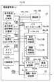
図14は現在策定が進められているHAViやJiniなどの家庭内の機器間の通信規格における各機器間の接続形態を示すブロック図である。図において、401および413はデジタル放送の受信可能なデジタルテレビ(DTV_A,DTV_B)である。ここで、401はセットトップボックス402を介してIEEE1394などのネットワークに接続され、セットトップボックス402とD端子などの画像専用ケーブル419に接続されている。
【0019】
413はIEEE1394デコーダを内蔵しているので、直接ネットワークに接続されている。404はPC(PC_A)である。403はそのディスプレイ装置(PC Display_A)である。418aはその専用画像ケーブルである。PC_A404、ディスプレイ装置403および専用画像ケーブル418aの構成は図13に対応する。また同様に、410はPC(PC_B)である。409はそのディスプレイ装置(PC Display_B)である。418bはその専用画像ケーブルである。
【0020】
ここで、PC_A404およびPC_B410はIEEE1394に接続されるが、これはディスプレイ装置への画像信号でなく、その他の信号の伝送に使用される。
【0021】
405は別系統のデジタルテレビのチューナ(DTV TUNER)である。406はデジタルビデオ(DV)である。411はDVDディスクプレーヤ(DVD)である。412は番組録画のためのハードディスク(HDD)からなるサーバである。
【0022】
これらのAV機器はIEEE1394に接続されており、相互に画像信号のやり取りを行う。414は公衆網416に接続されたモデム(modem)である。416は公衆網に接続される電話回線等である。407および408はIEEE1394信号を分岐して接続するためのハブである。417a〜417jはIEEE1394規格の通信線である。
【0023】
このように接続された家庭内ネットワークでは、ユーザはテレビ401、413で様々なソース(DTV TUNER、DV、DVD、HDD)が離れた場所から使用可能な環境を実現する。
【0024】
【発明が解決しようとする課題】
しかしながら、従来の家庭内ネットワークでは、PCが専用ケーブルで専用ディスプレイ装置と1対1に接続されるので、他のAV機器のように、デジタルテレビなどでネットワーク経由でPC画像を参照できなかった。
【0025】
また、専用ケーブルは、比較的太くて伝送距離を延ばせないので、PCとディスプレイ装置を近接して配置しなければならなかった。
【0026】
これはつぎのような原因に基づく。すなわち、第1の原因として、現在のディスプレイ装置の伝送方式では、同一線上に異なる画像信号を伝送した場合、伝送速度の制限を越えてしまう。例えば、XGAの解像度の場合(1024画素×768画素、60Hzの更新周期、画素周波数65MHz、各色8ビット)、情報量は1056Gbit/secで、IEEE1394の伝送速度400Mbit/secよりも、元々PC画像信号が多い。このため、TMDS等による特殊な伝送を行う専用ケーブルを使わざるを得なかった。画像圧縮を行うことにより、このデータ量を削減することは可能であるが、ネットワーク間での情報量の問題が残ってしまう。
【0027】
MPEG規格や部分書き換えなどの画像圧縮を行うことにより、単体では、情報量的に伝送可能になっても、家庭内のネットワーク構成で任意の場所から参照しようとした場合、同一の配線上を複数の画像信号が伝送されるので、伝送速度の許容量を越えてしまう可能性がある。
【0028】
特に、マルチ画面表示で複数の画面を表示した場合、回線を占有する画像信号が増加し、PCばかりでなく、現在ネットワークで伝送されることを前提に考えられているデジタルテレビでも、同様の問題を有すると考えられる。
【0029】
第2の原因として、現在のPCとディスプレイ装置の解像度決定方式は、1対1を前提とする考え方であるので、ネットワーク独特の多対多のシステムに対応していない。
【0030】
ディスプレイ装置からDDC通信でPCに転送する表示属性情報としてのEDIDデータは、Extended Display Identification Data Standard version3に記載されているように、表示可能な解像度の一覧を示すだけであり、実際の解像度は、これを参照したPCのグラフィック描画部を選択し、ディスプレイ装置に該当する解像度の出力信号を一方的に送り出す構成をとっている。
【0031】
このため、ディスプレイ装置は、送られた画像信号から解像度を判別することにより、どの解像度でPCから信号が送出されるかを推測しているのにすぎない。
【0032】
したがって、情報量の多い画像信号が、複数の信号源らか送られて伝送線路やディスプレイ装置の処理能力を越えて正しい表示ができなくなる等の問題が発生しても、ディスプレイ装置から対処が行えない。
【0033】
また、本来、ホストコンピュータとしての役割を演じているPCなどの信号源側も、信号源に接続したディスプレイ装置の表示能力を把握できるが、そのディスプレイ装置に接続した別の信号源の情報量まで把握できる構成でないので、こうした問題をシステムとして防止することができない。
【0034】
そこで、本発明は、信号源側は必要な画像領域に限った情報量を送信することができ、ネットワーク上の情報量を削減できる表示制御装置、表示制御システム、表示制御方法および記憶媒体を提供することを目的とする。
【0035】
また、本発明は、信号源側あるいはネットワーク上の任意の機器が任意の表示装置の任意の表示領域に現在どの信号源の画像が表示されているかを把握できる表示制御装置、表示制御システム、表示制御方法および記憶媒体を提供することを他の目的とする。
【0037】
【課題を解決するための手段】
上記目的を達成するために、本発明の請求項1に記載の表示制御装置は、伝送路に独立した装置として接続された複数の信号源からの映像信号を画面上の複数の表示領域にそれぞれ表示する制御を行う表示制御装置において、前記複数の信号源から入力される夫々の入力信号から映像信号に関する識別信号を取得する取得手段と、前記複数の信号源から入力される夫々の入力信号から映像信号を選択し、該映像信号が選択された入力信号から前記取得手段によって取得した識別信号に基づき、前記表示領域毎に、当該識別信号に対応する映像信号が夫々割り当てられる前記複数の信号源を特定する情報を含む表示信号選択情報を作成する表示信号選択情報作成手段と、該作成された表示信号選択情報にしたがって、前記夫々の映像信号を前記複数の表示領域に割り当てる表示選択手段と、前記作成された表示信号選択情報を前記伝送路に接続された複数の信号源に通知する通知手段とを備えたことを特徴とする。
【0069】
【発明の実施の形態】
本発明の表示制御装置、表示制御システム、表示制御方法および記憶媒体の実施の形態を図面を参照して説明する。
【0070】
[第1の実施形態]
図1は複数台の画像信号源に接続されたディスプレイ装置の構成を示すブロック図である。図2は画像信号源の構成を示すブロック図である。図において、1a、1b、1cは3台の画像信号源1、2、3としての画像出力装置(例えば、PC)であり、これらは同様の構成を有する。尚、図2における各部の構成は画像信号源3(1c)についても同様である。
【0071】
一方、30は画像表示装置(例えば、PC用のディスプレイ装置)である。本実施形態では、デジタル信号により画像信号および音声信号を伝送するディスプレイ装置が使用される。
【0072】
画像出力装置1a、1bにおいて、2a、2bはそれぞれCPU(中央演算装置)である。3a、3bはCPU2a、2bの制御信号を各部に伝えると共に、全体のデータバスおよび制御バスを制御するバスコントロール部である。
【0073】
20a、20bは各部を接続するデータバスおよび制御バスからなるシステムバス配線である。21a、21bはそれぞれCPU2aおよびバスコントロール部3a間、CPU2bおよびバスコントロール部3b間を接続するバス配線である。4a、4bは各PCのメインメモリである。5a、5bはハードディスクやフラッシュメモリなどの記録媒体である。6a、6bはディスプレイ用の画像信号を作成するグラフィック描画部である。本実施形態では、ディスプレイへの出力画像属性(解像度、画素周波数、画面の更新周波数、ガンマ特性、階調数、色特性など)に合わせた出力が行われる。
【0074】
7a、7bはグラフィック描画部6a、6bの画像処理時に用いられる画像メモリである。22a、22bはそれぞれグラフィック描画部6a、6bおよび画像メモリ7a、7b間を接続するデータバスおよび制御バスである。8a、8bはCD等の記録媒体やマイクから音声信号を作成する音源部である。9a、9bはグラフィック描画部6a、6bで作成された画像信号、および音源部8a、8bで作成された音声信号を、ディスプレイ装置に伝送するための画像・音声送信部である。これは、TMDS(Transition Minimized Differential Signaling)信号やMPEG信号に変換する部分、IEEE1394信号に変換して通信する部分等に相当する。また、画像の圧縮変換、部分書き換え信号への変換も画像・音声送信部9a、9bで行われる。
【0075】
23は画像信号源およびディスプレイ装置間の画像信号および音声信号の伝送線路である。24はPCおよびディスプレイ装置間の制御信号の伝送線路である。
【0076】
また、10a、11a、12a、13a、14aおよび10b、11b、12b、13b、14bはディスプレイ装置と通信を行うための部分である。10a、10bは通信部であり、EDID情報などの画像属性情報やエラー信号などと共に、領域毎の表示属性情報および表示信号選択情報を受信する。11a、11bは領域毎の表示属性情報記憶部であり、取得したディスプレイ装置のEDID情報および表示領域毎の表示属性情報を格納する部分である。
【0077】
14a、14bは各表示装置から受信した表示信号選択情報記憶部である。12a、12bは画像情報量制御部であり、ディスプレイ装置から受信した表示領域毎の表示属性情報および各表示装置での表示信号選択情報を受け、グラフィック描画部6a、6bを制御する部分である。13a、13bは音声情報量制御部であり、ディスプレイ装置から受信した表示領域毎の表示属性情報および各表示装置での表示信号選択情報を受け、音源部8a、8bを制御する部分である。尚、画像情報量制御部12a、12bおよび音声情報量制御部13a、13bは、CPU内部で実現される機能を表す。
【0078】
15a、15bは通信部10a、10bで受信した各信号源の表示領域毎の表示属性情報の表示属性情報記憶部11a、11bへの流れを示す。16a、16bは通信部10a、10bで受信した各信号源の表示信号選択情報の表示信号選択情報記憶部14a、14bへの流れを示す。
【0079】
17a、17bは表示領域毎の表示属性情報の表示属性情報記憶部11a、11bから画像情報量制御部12a、12bおよび音声情報量制御部13a、13bへの流れを示す。18a、18bは各信号源の表示信号選択情報の表示信号選択情報記憶部14a、14bから画像情報量制御部12a、12bおよび音声情報量制御部13a、13bへの流れを示す。
【0080】
26a、26bは画像情報量制御部12a、12bからグラフィック描画部6a、6bへの情報量制御信号の流れを示す。27a、27bは音声情報量制御部13a、13bから音源部8a、8bへの情報量制御信号の流れを示す。
【0081】
一方、画像表示装置30において、31はディスプレイ装置30を制御するマイコン部である。50はマイコン部30からの制御バスおよびデータバスからなる配線群である。32は画像・音声送信部9a、9bから伝送された画像信号および音声信号を受信するとともに、TMDSやIEEE1394フォーマットの信号をデコードしたり、圧縮データを伸長する画像・音声受信部である。
【0082】
33は画像信号源1、2からの画像の画素数をディスプレイ装置の表示画素数に合わせるための解像度変換や画面更新周波数の変換を行うためのメモリ制御部である。34はメモリ制御部33の信号処理に用いられる画像メモリである。51は画像メモリ34のデータバスおよび制御バスからなる配線群である。35は画像表示部36に用いられる液晶やCRTなどの特性に合わせてガンマ特性や色特性などを変換したり、オンスクリーンディスプレイなどの文字表示を行う画像表示用処理部である。
【0083】
36は液晶、CRT、PDP、EL、LED等の素子で構成される画像表示部である。52、53、54は画像のデータバスである。37は受信した音声信号をスピーカ38で再生するための信号に変換したり、増幅を行う音声処理部である。38がスピーカである。55は音声処理部37およびスピーカ38間の配線である。ここで、40、41、42、43、44、45は信号源との間の通信に関する部分である。
【0084】
40は通信部であり、従来のEDID情報などの表示部自体の表示属性情報やエラー信号などとともに、表示領域毎の表示属性情報および表示信号選択情報を信号源であるPC側に送信する。
【0085】
41は従来のEDID情報に加え、このディスプレイ装置の各表示領域毎の表示属性情報を格納する領域毎表示属性情報格納部である。42は受信した信号から各入力信号源の識別信号(通信アドレスやID番号など)あるいは各入力信号に付随する識別信号(通信アドレスやID番号など)の検出を行う入力信号識別信号取得部である。
【0086】
43はユーザ設定や外部からの設定などに基づいて表示領域を分割設定すると同時に、設定した各表示領域に表示する信号を選択する表示信号選択部である。44は表示信号選択部43の選択結果を受け、表示部のEDID情報を基に各表示領域毎の表示属性情報の作成、および識別した入力信号に対して表示信号選択情報の作成を行う通信情報作成部である。45は表示信号選択情報を記憶する表示信号選択情報格納部である。46はマウスや操作キーなどのユーザ操作部である。尚、入力信号識別信号取得部42、表示信号選択部43、通信情報作成部44はマイコン内部で実現される機能を表す。
【0087】
56は受信した画像信号の流れを示す。57は入力信号識別信号取得部42で取得した識別信号の流れを示す。58はユーザ設定部46による表示信号選択に関する制御信号の流れを示す。59は各表示領域毎の表示属性情報の授受の流れを示す。60は表示信号選択部43による表示信号の選択にしたがってメモリ制御部33を制御する信号の流れを示す。
【0088】
61は表示信号選択部43による表示信号の選択結果を通信情報作成部44に伝える制御信号の流れを示す。62は通信情報作成部44により作成された表示信号選択情報の表示信号選択情報格納部45への流れを示す。63は領域毎表示属性情報格納部41から通信部40への領域毎の表示属性情報の流れを示す。64は表示信号選択情報格納部45から通信部40への表示信号選択情報の流れを示す。
【0089】
23は画像・音声信号を伝送する伝送線路である。24は制御信号の伝送線路である。図において、伝送線路23、24は別々に示されているが、実際にはTMDSやIEEE1394などの信号線がカスケード接続やツリー接続された機器間で同一のネットワーク通信線路上で同一の送受信部により通信が行われるようにしてもよい。
【0090】
上記構成を有する表示制御システムの動作を示す。図3は画像表示装置30の表示設定処理手順を示すフローチャートである。この処理プログラムはマイコン部31内のROM(図示せず)に格納されており、同じくマイコン部内のCPU(図示せず)によって実行される。
【0091】
まず、現在の表示領域毎の表示属性情報(EDID情報)を領域毎表示属性情報格納部41から読み出す(ステップS1)。ネットワークに接続されている信号源に対し、読み出した表示領域毎の表示属性情報を通信し、現在、画像表示装置30が各表示領域を表示するために必要なそれぞれの画像属性情報を通知する(ステップS2)。
【0092】
表示信号選択情報格納部45から各表示領域に現在どの入力信号を表示するように設定されているかを示す表示信号選択情報を読み出すとともに(ステップS3)、読み出したこの情報を領域毎の表示属性情報と同様、各画像信号源に通知する(ステップS4)。この結果、各表示領域に割り当てられた画像信号源は、通知された領域毎の表示属性情報に応じて画像情報を出力すると同時に、他の画像信号源からどのような信号が出力されるかを知ることが可能になる。
【0093】
画像信号源が表示領域毎の表示属性情報に応じて出力してきた画像情報を画像・音声受信部32で受信する(ステップS5)。また、このとき同時に、入力信号識別信号取得部42で入力された識別信号を取得する。受信した各画像信号をメモリ制御部33で各表示領域に合った画像に変換するとともに、画像表示部用の信号に合成する(ステップS6)。
【0094】
表示信号を変更するか否かを判別する(ステップS7)。表示信号を変更する場合、ユーザ操作部46などにより、変更する表示領域に表示する信号を入力信号から選択し、表示選択情報を作成して変更する(ステップS9)。この後、ステップS3の処理に戻り、再度、設定し直す。
【0095】
一方、ステップS7で表示信号を変更しない場合、表示領域を変更するか否かを判別する(ステップS8)。表示領域を変更する場合、マウスやデジタイザなどのユーザ操作部などにより、変更する表示領域の大きさや位置を指定するとともに、表示領域毎の表示属性情報を作成して変更を行い(ステップS10)、ステップS1の処理に戻り、再度、設定し直す。一方、ステップS8で表示領域を変更しない場合、この処理を終了する。
【0096】
このように、画像表示装置の構成を、領域毎の表示属性情報を伝送可能な構成とすることにより、画像信号源側では必要な画像領域に限った情報量を送信することが可能になり、ネットワーク上の情報量が削減される。また、識別した入力信号に対して割り当てた表示領域を示す表示信号選択情報を伝送する構成としたことにより、画像信号源側あるいはネットワーク上の任意の機器では、任意の表示装置の任意の表示領域に現在どの信号源の画像が表示されているかを把握可能となり、ネットワーク上の通信量を管理可能なシステムを実現することができる。
【0097】
ここで、領域毎の表示属性としては、画像表示領域の画素数、大きさ、平面上での位置関係、ウインドウ同士の重なりの位置関係(前面配置や後面配置など)、画面の更新周期(リフレッシュレートや部分書き換え周期)、階調数、輝度、ガンマ特性、コントラスト、色特性、色数、アスペクト比や伝送方式(伝送方式、圧縮方式、圧縮率、書き換え周期等)の情報など表示に関わる情報であればよく、特に限定されない。
【0098】
また、領域毎の表示属性情報および表示信号選択情報の通信は、ユーザ操作部による入力系統の変更、表示画面の変更による表示信号の変更、画像表示部の画面上の表示領域の大きさや位置など表示領域の変更時以外にも、映像信号入力部(画像・音声受信部32)に入力する信号数やネットワーク上の信号数の変化時、入力する信号やネットワーク上の信号の属性の変化時、画像表示部36の画面領域の用途の変更時、画像入力部(画像・音声受信部32)に入力する各画像の内容の変更時、画像表示部36の画面上の複数の子画面同士の配置関係の変更時、画像信号源からの要求信号があった時、画像信号源の接続や電源の投入を検出した時など、従来のディスプレイ装置およびPC間での通信時に限らず、ネットワーク上での任意のタイミングで表示属性情報および表示信号選択情報の通信を行うようにすることにより、ネットワーク特有の多対多接続に対しても、柔軟な表示制御システムを実現することが可能である。
【0099】
また、表示信号選択情報は、入力信号から取得した識別信号に対して作成されるが、この識別信号は、入力された映像信号の信号源に対して与えられた識別番号や通信アドレス、入力映像信号の信号源の出力モード毎に与えられた識別番号や通信アドレス、入力映像信号の信号源の出力チャンネル毎に与えられた識別番号や通信アドレス、入力映像信号自身に対して与えられた識別番号や通信アドレス、入力映像信号の信号源の使用者に対して与えられた識別番号や通信アドレスなど、信号の送信元が表示装置やネットワーク接続された他の機器に認識されるものであればよい。
【0100】
図4は領域毎の表示属性情報の通信フォーマットを示す図である。図において、H1は受信先の通信アドレスであり、例えば、画像表示装置に対して与えられた通信アドレスや識別番号(ID)、あるいは画像表示装置のチャンネル画面やウインドウ画面に対して与えられた通信アドレスや識別番号(ID)などである。受信先の通信アドレスはaバイトの信号であり、例えば4バイト程度の大きさである。
【0101】
H2は送信元の通信アドレスであり、画像信号源に対して与えられた通信アドレスや識別番号(ID)、あるいは画像信号自身に与えられた通信アドレスや識別番号(ID)である。送信元の通信アドレスは、bバイトの信号であり、例えば4バイト程度の大きさである。画像表示装置30で検出される識別信号はこの部分のデータに相当する。
【0102】
H3は画像表示装置30に設定されたチャンネル画面やウインドウ画面などの表示領域毎に割り振られた識別番号(ID)である。識別番号(ID)はcバイトの信号であり、例えば1バイト程度の大きさである。H4は表示属性情報部分であり、dバイトの信号である。H5はデータの終了等を示す部分であり、例えば、チェックサム部分等である。この部分はeバイト、実際には1バイト程度の大きさである。
【0103】
図5は表示信号選択情報の通信フォーマットを示す図である。図において、H1、H2、H3、H5は図4と同じである。H6は表示信号選択情報部分であり、fバイトの大きさである。
【0104】
このような表示制御システムで情報量を管理して表示を行う場合を示す。説明を簡単にするため、1秒当たりの情報量は画素数×リフレッシュレート×ビット数(単位bps)とする。図6は画像表示装置30の表示画面を示す図である。この画像表示装置は、QXGA(2048x1536画素)の画素数を有しており、図中、F1は表示領域全体を示す。F2はこの画像表示装置に接続された画像信号源3(1c)としてのPCの表示画像を示している。この画像の解像度はQXGA(2048x1536画素)であり、表示領域全体F1に表示を設定している。また、画像内容としては、PCの作業画面が表示されており、ワードプロセッサやグラフを出力する。
【0105】
子画面領域F3は、この画像表示装置に接続された画像信号源1としてのPC1aの表示画像に設定されている。ここでは、野球の結果などの情報を含むインターネットのホームページ画像SXGA(1280x1024)を出力する。
【0106】
子画面領域F4は、この画像表示装置に接続された画像信号源2としてのPC1bの表示画像に設定されている。ここでは、記録媒体5bの1つであるDVD再生部で再生されたHDTV(1920x1080画素)の映画の画像を出力する。
【0107】
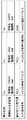
図7は表示領域毎の表示属性、信号源、入力識別信号を示すテーブルである。画像表示装置30は、各表示領域毎の表示属性情報および各表示領域に割り当てられた信号源の表示選択情報をネットワーク上の機器に通信する。表示領域毎の表示属性情報として、画像信号源1aに対し、1024x768の解像度、階調数8ビットなどの画像表示属性情報を伝達する。また、画像信号源2aに対し、720x480の解像度、階調数8ビットなどの画像表示属性情報を伝達する。
【0108】
この表示領域毎の画像表示属性情報を受け取ることにより、画像信号源1は元々、SXGA(1280x1024)の画像を、予めXGA(1024x768)の解像度に変換して出力する。また、画像信号源2は、元々、HDTV(1920x1080)の画像を720x480の解像度に変換して出力する。
【0109】
これにより、元々、3.1Gbpsであった画像信号量を、各信号源は、つぎの通り、2.1Gbpsに低減して出力する。
【0110】
F2:QXGA=2048x1536x60x8=1.5Gbps
F3:SXGA=1280x1024x60x8= 0.6Gbps
F4:HDTV=1920x1080x60x8=1.0Gbps
合計3.1Gbps
F2:QXGA=2048x1536x60x8=1.5Gbps
F3:XGA=1024x768x60x8= 0.4Gbps
F4:SDTV=720x480x60x8=0.2Gbps
合計2.1Gbps
図8は表示領域を変更した場合の画像表示装置の表示画面を示す図である。表示領域F4を変更し、HDTV(1920x1080)の解像度に拡大した場合、画像信号源2および他のネットワーク上の機器に対し、図9に示すような新しい表示領域毎の表示属性および表示信号選択情報を通信する。図9は表示領域毎の表示属性、信号源、入力識別信号を示すテーブルである。
【0111】
この表示領域の変更によって、ネットワーク上の信号量は、つぎのように、2.9Gbpsになると計算される。
【0112】
F2:QXGA=2048x1536x60x8=1.5Gbps
F3:XGA=1024x768x60x8= 0.4Gbps
F4:HDTV=1920x1080x60x8=1.0Gbps
合計2.9Gbps
ここで、このネットワーク上の伝送可能な上限値が2.5Gbpsであることはこの表示制御システムで認識されている。したがって、このシステムの情報量の管理を信号源側で行う場合、3つの画像のうち、表示領域F4のHDTV以外の動画特性を重視していないので、画像信号源3および画像信号源1はそれぞれの出力画像を60Hzではなく30Hzの更新周波数で出力するように判断する。
【0113】
これにより、つぎの通り、情報量を伝送可能な値に制御する。
【0114】
F2:QXGA=2048x1536x30x8=0.8Gbps
F3:XGA=1024x768x30x8= 0.2Gbps
F4:HDTV=1920x1080x60x8=1.0Gbps
合計2.0Gbps
このように、画像表示装置が表示領域毎の表示属性情報および表示信号選択情報を通信し、ネットワーク上に接続された任意の機器が伝送情報量を制御し、伝送情報過剰による画質の劣化や通信の不具合を防ぎ、良好な多画面表示を実現する。
【0115】
ディスプレイ装置の情報を画像出力装置が入手する方法としては、従来のDDC通信によるEDIDデータ(現在Ver.3.0)のやりとり、HAVi(Home Audio/Video Interoperability)規格(現在Ver1.0)が知られているが、いずれも全ディスプレイ領域の情報(表示画素数、アスペクト比、MPEG圧縮フォーマットの伝送等)の通信しか想定していない。
【0116】
このため、ディスプレイ装置で設定された任意の画面表示領域に複数の映像信号を伝送する場合、各映像信号源からの出力は、子画面であっても全ディスプレイ領域の場合と同じ信号を送らなければならず、映像信号の伝送線路の情報量の上限を越えてしまうおそれがある。
【0117】
また、前述したように、DDC通信においては、ディスプレイ装置から信号源へのEDID情報の一方通行であるので、ディスプレイ装置が入力する画像信号の解像度を正確に把握できない点、通信を行う時期もPCの起動時とディスプレイ装置と信号源を物理的に接続した時に限られている点から、表示を行いながら画像や音声の情報の属性(表示領域や解像度、圧縮率、伝送形式等)の変更や情報量の制御(情報の選択、停止、開始、圧縮率の変更など)の通信ができなかった。
【0118】
さらに、PCなどの信号源が自身の出力する映像信号を把握するだけでは、複数の信号源の間で相互の画像情報量が互いに不明となるので、同じディスプレイ装置の入力系統に入力する画像信号の総量が許容量を越えるなどの問題があっても、その不具合の検出や相互の制御による情報量の削減を行うことができなかった。
【0119】
特開平10−234020号公報には、複数機器間での画像の送受信において、送信側で伝送量を減らす通信方法が開示されているが、これは専用の送受信装置を前提としたものであり、異なる機器が接続された環境では、画像情報量の管理を行うことができない。
【0120】
本実施形態では、ディスプレイ装置側に表示領域毎の表示属性情報を通信する手段、および表示信号選択情報を通信する手段を設けたことにより、情報量自体を抑えると共に、ネットワーク上の異なる種類の機器との間で伝送量を把握する情報を伝達する手段を設けたことにより、新規の信号や信号源の出力属性の変化にも柔軟に対応する表示制御システムを実現することができる。
【0121】
尚、通信量を抑制する手段として、適用可能な制御方法には、上記実施形態で示した画像表示領域の制限(子画面領域を非表示)、画面の画素数(解像度)の変更、画面の更新周期の変更の他、各伝送信号の画像属性(画面の更新周期、階調数、色、アスペクト比等)や伝送方式(伝送方式、圧縮方式、圧縮率、書き換え周期等)の変更などが挙げられる。
【0122】
[第2の実施形態]
第2の実施形態は、ネットワーク上で画像伝送による表示に適用し、部分書き換えによるPCからの画像圧縮信号、DTVチューナからのMPEG2圧縮信号などの異なるフォーマットの信号を、IEEE1394等の同じ画像伝送線上に伝送する場合を示す。
【0123】
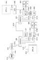
図10は第2の実施形態における表示制御システムの構成を示すブロック図である。この表示制御システムはネットワークに接続された機器から構成される。
【0124】
図において、101および113は多画面表示を行うディスプレイ装置である。ディスプレイ装置101は、セットトップボックス(STB)102を介してIEEE1394等のネットワークに接続され、STB102とTMDS伝送方式等の画像専用のケーブル119で接続される。また、ディスプレイ装置113は、IEEE1394デコーダを内蔵しているので、直接、ネットワークに接続されている。STB102およびディスプレイ装置113はそれぞれ本発明の表示制御装置および画像表示装置に相当する。104はPC(PC_A)、110はPC(PC_B)である。PC104、110の表示もネットワークを介してディスプレイ装置101、113で行われる。
【0125】
105は別系統のデジタルテレビのチューナ(DTV TUNER)である。106はデジタルビデオ(DV)である。111はDVDディスクプレーヤ(DVD)である。112は番組録画のためのハードディスク(HDD)からなるサーバである。これらのAV機器はIEEE1394に接続されており、相互に画像信号のやり取りを行う。
【0126】
114は公衆網115に接続されるモデム(modem)である。116は公衆網に接続される電話回線等である。107および108はIEEE1394信号を分岐して接続するためのハブである。117a〜117jはIEEE1394規格の通信線である。
【0127】
このように接続された家庭内ネットワークにおいて、ユーザはテレビ(ディスプレイ装置)101、113で様々なソース(PC_A、PC_B、DTV TUNER、DV、DVD、HDD)が離れた場所から使用可能な環境を実現する。PC_A、PC_Bのキーボードやマウスなどの操作入力手段は図示されていないが、画像と同様、IEEE1394等を介して各ディスプレイ装置の近くから操作される。
【0128】
図10に示すネットワークを用いて、前記第1の実施形態と同様、図6および図8の表示を実現する場合を示す。画像表示装置はQXGA(2048x1536)の画素数を有する表示装置である。図中、F1はこの表示領域全体を示す。F2はこの画像表示装置に接続されたPCの表示画像の表示領域を示す。この画像の解像度はQXGA(2048x1536画素)であり、表示領域全体(画面全体)F1に表示が行われる。画像の内容としては、PCの作業画面が表示されており、ワードプロセッサやグラフが表示されている。
【0129】
子画面領域F3には、この画像表示装置に接続されたPCの表示画像が示されている。野球の結果などの情報を含むインターネットのホームページ画像SXGA(1280x1024)はXGA(1024x768)の領域に表示されている。また、子画面領域F4では、HDTVの1920x1080画素の解像度の映像を1024x576画素の解像度に変換したデジタルテレビチューナの画像を親画面の1/4領域に表示することも可能である。
【0130】
このように、画面領域を分割してネットワーク上の複数の機器の画像を多画面表示するために、各表示領域毎の表示属性情報および表示信号選択情報を伝送可能な構成を有する。
【0131】
これにより、信号源側もしくはネットワーク上の任意の機器は、表示領域に合った必要分だけの画像情報を伝送すると共に、任意の表示装置の任意の表示領域に現在どの信号源の画像が表示されているかを把握し、ネットワーク上の通信量を削減して管理可能な表示制御システムを構築することができる。
【0132】
ここで、図6、図8の親画面の画像を送出する信号源をPC110とし、子画面画像領域F3の画像を送出する信号源をPC104とし、子画面領域画像領域F4の画像を送出する信号源をチューナ105とする場合を示す。また、これらの画像合成を行い、ディスプレイ装置101の表示制御を行う表示制御装置をセットトップボックス102とする。
【0133】
図11は表示制御システムにおけるPC104およびDTVチューナ105の具体的構成を示すブロック図である。図12は表示制御システムにおけるセットトップボックス102およびディスプレイ装置101の具体的構成を示すブロック図である。セットトップボックス102は、ネットワークを介した各信号源からの画像信号を合成するとともに、ディスプレイ装置の表示出力に変換する。
【0134】
PC104において、202はCPU(中央演算装置)である。203はこのCPU202の制御信号を各部に伝えると共に、全体のデータバス、制御バスを制御するバスコントロール部である。211aは各部を接続するデータバスおよび制御バスからなるシステムバス配線である。211bはCPU202およびバスコントロール部203間のバス配線である。
【0135】
204はPC104のメインメモリである。205はハードディスクなどの記録媒体である。206はディスプレイ用の画像信号を作成するグラフィック描画部である。ここで、ディスプレイ装置への出力画像属性(解像度、画素周波数、画面の更新周波数、ガンマ特性、階調数、色特性など)に合わせた出力が行われる。
【0136】
207はグラフィック描画部206の画像処理時に用いられる画像メモリである。211eはグラフィック描画部206および画像メモリ207間のデータバスおよび制御バスである。208はグラフィック描画部206で作成された画像信号を、ディスプレイ装置に伝送するための部分書き換え信号に変換して圧縮する画像エンコード部である。
【0137】
209は圧縮された部分書き換え信号をIEEE1394信号に変換して通信するIEEE1394通信部分である。212はディスプレイ装置101から受信した表示領域毎の表示属性情報および表示信号選択情報を受け、グラフィック描画部206などを制御する情報量制御部である。213はディスプレイ装置101から通信された表示領域毎の表示属性情報を記憶する表示属性情報記憶部である。214はディスプレイ装置101から通信された表示信号選択情報を記憶する表示信号選択情報記憶部である。
【0138】
チューナ105において、238はチューナ105を制御するマイコン部である。248aはこのマイコン部238からの制御バスおよびデータバスからなる配線群である。239はアンテナから信号を受信してMPEG信号を出力するチューナ部である。240はこのMPEG信号をデコードしてビデオ出力用の信号として出力するMPEGデコード部である。248bはその信号出力線である。
【0139】
241は圧縮形式の変換部であり、読み出したMPEG信号を任意の解像度や画面更新周波数の圧縮信号に変換する。242は圧縮した画像信号をIEEE1394信号に変換して通信するIEEE1394通信部である。243はディスプレイ装置101から通信された領域毎の表示属性情報を記憶する表示属性情報記憶部である。
【0140】
244はディスプレイ装置101から通信された表示信号選択情報を記憶する表示信号選択情報記憶部である。245はディスプレイ装置101から受信した領域毎の表示属性情報および表示信号選択情報を受け、グラフィック描画部等を制御する情報量制御部である。
【0141】
STB102において、215はユーザが入力操作を行うユーザ操作部である。216はこのSTB102を制御するCPU部である。217aはこのCPU部216の制御バスおよびデータバスからなる配線群である。218はIEEE1394通信部である。219aはIEEE1394から入力した圧縮画像のうち、部分書き換え画像信号などをデコードし、画像合成のための演算に使用可能なRGB24ビットなどの信号に変換するデコーダである。219bはIEEE1394から入力した圧縮画像のうち、MPEG系の圧縮信号などをデコードし、画像合成のための演算に使用可能なRGB24ビットなどの信号に変換するデコーダである。
【0142】
217b、217cはデコードされた画像信号のデータバスである。220はこれらの複数のデコーダ219a、219bからの出力を合成する画像合成部である。221は画像合成のためのメモリである。217dはこのメモリ用のの制御バスおよびデータバスからなる配線群である。222は合成した画像信号を画像表示部に用いられる液晶やCRTなどの特性に合わせてガンマ特性や色特性などを変換したり、オンスクリーンディスプレイなどの文字表示を行う画像信号処理部である。223は液晶、CRT、PDP、EL、LEDなどの素子で構成される画像表示装置101に信号を出力するためのVGA規格、DVI規格などの画像送信部である。217eおよび217fは画像信号のデータバスである。
【0143】
224はディスプレイ装置101との間でEDID情報を通信するためのDDC通信部である。225は各領域毎の表示属性情報を格納する領域毎表示属性情報格納部である。226は受信した信号から各入力信号源の識別信号(通信アドレスやID番号など)あるいは各入力信号に付随する識別信号(通信アドレスやID番号など)の検出を行う入力信号識別信号取得部である。
【0144】
227はユーザ設定や外部からの設定等に基づいて表示領域を分割設定すると同時に、設定した各表示領域に表示する信号を選択する表示信号選択部である。229は表示信号選択部227の選択結果から表示部のEDID情報を基に、各表示領域毎の表示属性情報の作成および識別した入力信号に対して表示信号選択情報の作成を行う表示実行情報作成部である。
【0145】
228はこの表示信号選択情報を記憶する表示信号選択情報格納部である。ここで、入力識別信号取得部226、表示信号選択部227、表示実行情報作成部229はCPU内部で実現される機能を示す。
【0146】
ディスプレイ装置101において、230はこのディスプレイ装置101を制御するマイコン部である。237aはこのマイコン部230からの制御バスおよびデータバスからなる配線群である。231はPCやSTB等との間でEDID情報を通信するためのDDC通信部である。232はSTB102から伝送されたVGA規格やDVI規格などの画像信号を受信し、RGB各色8ビットなどの信号処理に適したフォーマットに変換する画像受信部である。
【0147】
233は受信した画像の画素数をディスプレイ装置101の表示画素数に合わせるための解像度変換や画面更新周波数の変換を行う解像度変換部である。234は解像度変換部233の処理で用いられる画像メモリである。237bは画像メモリ234の制御バスおよびデータバスからなる配線群である。235は画像表示部に用いられる液晶、CRTなどの特性に合わせてガンマ特性や色特性などを変換したり、オンスクリーンディスプレイなどの文字表示を行う画像表示用処理部である。
【0148】
236は液晶、CRT、PDP、EL、LEDなどの素子で構成される画像表示部である。237c〜237eは画像信号のデータバスである。各機器間において、251および252はIEEE1394などの通信線を表わしており、この配線により同じ伝送プロトコルに則った異なる圧縮方式の画像信号の通信が行われる。また、情報量制御信号の通信も同じ伝送経路で行われる。
【0149】
245は従来からのVGA規格やDVI規格などの画像専用ケーブルで接続された画像信号の配線を示している。246は従来からのDDC通信の通信線を示している。
【0150】
STB102において、250aはデコーダA(219a)で検出された入力の識別信号である。250bはデコーダB(219b)で検出された入力の識別信号の流れを示す。250dは表示実行情報作成部229から表示属性情報格納部225への信号の流れを示す。250eは表示属性情報格納部225から通信部218への領域毎の表示属性情報の流れを示す。
【0151】
250fはユーザ設定部による表示信号選択に関する制御信号の流れを示す。250gは入力識別信号取得部226から取得した識別信号の表示信号選択部227への流れを示す。250hは表示信号選択部227による表示信号の選択にしたがって画像合成部220を制御する信号の流れを示す。250iは表示信号選択部227による表示信号の選択結果を表示信号選択情報作成部229に伝える制御信号の流れを示す。250jは表示実行情報作成部229により作成された表示信号選択情報格納部228への流れを示す。250kは表示信号選択情報格納部228から通信部218への表示信号選択情報の流れを示す。
【0152】
PC104において、248aは受信したIEEE1394信号のうち、領域毎の表示属性情報の表示属性情報記憶部213への流れを示す。248bは表示属性情報記憶部213から読み出した領域毎の表示属性情報の情報量制御部212への流れを示す。248cは受信したIEEE1394信号のうち、表示信号選択情報の表示信号選択情報記憶部214への流れを示す。248dは表示信号選択情報記憶部214から読み出した表示信号選択情報の情報量制御部212への流れを示す。248eは情報量制御部212からグラフィック描画部206への制御信号の流れを示す。
【0153】
チューナ105において、249aは受信したIEEE1394信号のうち、領域毎の表示属性情報の表示属性情報記憶部243への流れを示す。249bは表示属性情報記憶部243から読み出した領域毎の表示属性情報の情報量制御部245への流れを示す。249cは受信したIEEE1394信号のうち、表示信号選択情報の表示信号選択情報記憶部244への流れを示す。249dは表示信号選択情報記憶部244から読み出した表示信号選択情報の情報量制御部245への流れを示す。249eは情報量制御部245からMPEGデコーダ部240および圧縮変換部241への制御信号の流れを示す。
【0154】
第2の実施形態では、ディスプレイ装置101の構成は従来と同様であるが、セットトップボックス(STB)102は領域毎の表示属性情報および表示信号選択情報を各信号源と通信することにより、信号源からの伝送情報量を抑制すると共に、信号源やネットワーク上の任意の機器がネットワーク上の情報量の管理を行う。また、セットトップボックス102はディスプレイ装置101との間でDDC通信により得られたEDID情報を参照し、領域毎の表示属性情報を作成する。
【0155】
第2の実施形態の表示制御システムでは、前記第1の実施形態と同様のフローチャートにしたがって表示画像の設定が行われる。図11、図12を参照しながら、この表示設定動作を図3のフローチャートしたがって示す。この処理プログラムはセットトップボックス102内のCPU部216内のROM(図示せず)に格納されており、CPUによって実行される。
【0156】
まず、現在の領域毎の表示属性情報(EDID情報)を領域毎の表示属性情報格納部225から読み出す(ステップS1)。ネットワークで接続されている信号源に対し、この領域毎の表示属性情報を通信し、現在、この画像表示装置101が各領域を表示するために必要なそれぞれの画像属性を通知する(ステップS2)。
【0157】
表示信号選択情報格納部228から各表示領域に現在どの入力信号を表示するように設定されているのかを読み出すとともに(ステップS3)、この情報を領域毎の表示属性情報と同様、各信号源に対して通知する(ステップS4)。この結果、各表示領域に割り当てられた信号源は通知された表示領域毎の表示属性情報に応じて画像情報を出力すると同時に、他の信号源からどのような信号が出力されるかを知ることが可能になる。
【0158】
信号源が表示領域毎の表示属性情報に応じて出力してきた画像情報をIEEE1394通信部218で受信する(ステップS5)。このとき、入力識別信号取得部226により識別信号を取得する。
【0159】
受信した各画像信号を画像合成部220で各表示領域に合った画像に変換するとともに、画像表示部用の信号に合成する(ステップS6)。表示信号の選択を変更するか否かを判別し(ステップS7)、表示信号を変更する場合、ユーザ操作部215等により変更する表示信号を入力する信号から選択し、表示選択情報を作成して変更を行った後(ステップS9)、ステップS3の処理に戻り、再度、設定し直す。
【0160】
一方、ステップS7で表示信号を変更しない場合、表示領域を変更するか否かを判別し(ステップS8)、表示領域を変更する場合、マウスやデジタイザなどのユーザ操作部215などにより、変更する表示領域の大きさや位置を指定するとともに、領域毎の表示属性情報を作成して変更を行った後(ステップS10)、ステップS1の処理に戻り、再度、設定し直す。一方、ステップS8で表示領域を変更しない場合、この設定処理を終了する。
【0161】
このように、領域毎の表示属性情報を伝送可能な構成とすることにより、信号源側では必要な画像領域に限った情報量を送信することが可能になり、ネットワーク上の情報量を削減することができる。
【0162】
また、表示信号選択情報を伝送可能な構成とすることにより、信号源側あるいはネットワーク上の任意の機器は、任意の表示装置の任意の表示領域に現在どの信号源の画像が表示されているかを把握可能であり、ネットワーク上の通信量を管理可能なシステムを実現することができる。
【0163】
また、画像信号およびその他の制御信号が同一のネットワークで伝送可能であるばかりでなく、従来のVGA規格やDVI規格のTMDS方式のケーブルのように、比較的太くて伝送距離が10m以下の専用のケーブルを用いる必要が無くなる。これにより、PC本体とディスプレイ装置は距離を離して設置可能である。
【0164】
さらに、DVDやデジタル放送、DVなどのAV系の家電ネットワークとPCの画像が統合可能になり、同じ表示装置上で同じ制御手段により制御可能になる。
【0165】
尚、以上が本発明の実施の形態の説明であるが、本発明は、これら実施の形態の構成に限られるものではなく、特許請求の範囲で示した機能、または実施の形態の構成が持つ機能が達成できる構成であればどのようなものであっても適用可能である。
【0166】
また、本発明は、前述した実施形態の機能を実現するソフトウェアのプログラムコードを記憶した記録媒体を、システムあるいは装置にプログラムを供給することによって達成される場合にも適用できることはいうまでもない。この場合、記憶媒体から読み出されたプログラムコード自体が本発明の新規な機能を実現することになり、そのプログラムを記憶した記憶媒体は本発明を構成することになる。
【0167】
上記実施形態では、図3のフローチャートに示すプログラムコードは記憶媒体であるROMに格納されている。プログラムコードを供給する記憶媒体としては、例えばフロッピーディスク、ハードディスク、光ディスク、光磁気ディスク、CD−ROM、CD−R、DVD、磁気テープ、不揮発性のメモリカードなどを用いることができる。
【0169】
【発明の効果】
本発明によれば、表示信号選択情報を伝送可能な構成とすることにより、信号源側あるいはネットワーク上の任意の機器が任意の表示装置の任意の表示領域に現在どの信号源の画像が表示されているかを把握することができる。これにより、ネットワーク上の画像情報量を管理するシステムを実現できる。
【図面の簡単な説明】
【図1】複数台の画像信号源に接続されたディスプレイ装置の構成を示すブロック図である。
【図2】画像信号源の構成を示すブロック図である。
【図3】画像表示装置30の表示設定処理手順を示すフローチャートである。
【図4】領域毎の表示属性情報の通信フォーマットを示す図である。
【図5】表示信号選択情報の通信フォーマットを示す図である。
【図6】画像表示装置30の表示画面を示す図である。
【図7】表示領域毎の表示属性、信号源、入力識別信号を示すテーブルである。
【図8】表示領域を変更した場合の画像表示装置の表示画面を示す図である。
【図9】表示領域毎の表示属性、信号源、入力識別信号を示すテーブルである。
【図10】第2の実施形態における表示制御システムの構成を示すブロック図である。
【図11】表示制御システムにおけるPC104およびDTVチューナ105の具体的構成を示すブロック図である。
【図12】表示制御システムにおけるセットトップボックス102およびディスプレイ装置101の具体的構成を示すブロック図である。
【図13】従来の一般的なディスプレイ装置としてのパーソナルコンピュータ用のディスプレイ装置の構成を示すブロック図である。
【図14】現在策定が進められているHAViやJiniなどの家庭内の機器間の通信規格における各機器間の接続形態を示すブロック図である。
【符号の説明】
1a、1b、1c 信号源
23、24 伝送路
30 画像表示装置
31 マイコン部
41 領域毎表示属性情報格納部
42 入力信号識別信号取得部
43 表示信号選択部
44 通信情報作成部
45 表示信号選択情報格納部
46 ユーザ操作部[0001]
BACKGROUND OF THE INVENTION
The present invention relates to a display control device, a display control system, a display control method, and a storage medium.
[0002]
[Prior art]
Conventionally, with the development of communication technology, networking in offices has progressed, and various devices, such as PCs, have been connected to each other to share functions. In recent years, standardization of communication between home devices such as HAVi and Jini has progressed with interfaces such as IEEE 1394 and USB, and networking of devices in the home has also progressed.
[0003]
On the other hand, the displays of TV sets and personal computers (PCs) were completely different from each other before. However, the mutual integration has progressed, and TVs that can display PC images and PC displays that can input TV signals have appeared. .
[0004]
In addition, large-screen display devices such as wide-screen TVs, plasma displays, rear-type projection TVs, and projection-type projectors offer a variety of video sources such as movies, TVs, home videos, presentations, video conferences, and various materials. There are an increasing number of scenes where people use the phone in offices and homes. Under such circumstances, there is a demand for a multi-screen display function for displaying a plurality of images from different image signal sources in one screen.
[0005]
FIG. 13 is a block diagram showing a configuration of a display device for a personal computer as a conventional general display device. In the figure,
[0006]
In the
[0007]
[0008]
[0009]
[0010]
In accordance with this communication method, display attribute information in the EDID (Extended Display Identification Data) format, which is also standardized by VESA, is transmitted from the display device side to the PC side. The standard is issued as Extended Display Identification Data Standard version 3 (Revision Date November 13, 1997).
[0011]
The DVI standard also adopts this DDC communication to perform communication between the display device and the PC, and specifies a hot plug function (a function for detecting DDC communication when the display and the PC are connected). A
[0012]
For example, when the display is not connected, the
[0013]
On the other hand, in the
[0014]
[0015]
A
[0016]
[0017]
As shown in this example, a conventional PC display device is basically connected to a PC that outputs an image on a one-to-one basis. The resolution of the display screen is determined by exchanging EDID data by DDC communication when the PC is started or when connection between the PC and the display device is detected.
[0018]
FIG. 14 is a block diagram showing a connection form between devices in a communication standard between home devices such as HAVi and Jini that are currently being developed. In the figure,
[0019]
Since 413 has a built-in
[0020]
Here,
[0021]
[0022]
These AV devices are connected to IEEE1394 and exchange image signals with each other.
[0023]
In the home network connected in this way, the user realizes an environment in which various sources (DTV TUNER, DV, DVD, HDD) can be used on
[0024]
[Problems to be solved by the invention]
However, in the conventional home network, since the PC is connected to the dedicated display device on a one-to-one basis using a dedicated cable, it is not possible to refer to the PC image via the network on a digital television or the like as with other AV devices.
[0025]
Further, since the dedicated cable is relatively thick and the transmission distance cannot be extended, the PC and the display device have to be arranged close to each other.
[0026]
This is based on the following causes. That is, as a first cause, in the transmission method of the current display apparatus, when different image signals are transmitted on the same line, the transmission speed limit is exceeded. For example, in the case of XGA resolution (1024 pixels × 768 pixels, 60 Hz update period, pixel frequency 65 MHz, each
[0027]
Even if it becomes possible to transmit information alone by performing image compression such as MPEG standard or partial rewriting, if it is attempted to refer from an arbitrary place in a home network configuration, a plurality of parts on the same wiring are used. Therefore, there is a possibility that the allowable transmission speed is exceeded.
[0028]
In particular, when a plurality of screens are displayed in a multi-screen display, the image signal that occupies the line increases, and the same problem occurs not only in the PC but also in digital TVs that are currently considered to be transmitted over a network. It is thought that it has.
[0029]
As a second cause, the current resolution determination method of the PC and the display device is based on a one-to-one concept and does not support a many-to-many system unique to a network.
[0030]
The EDID data as display attribute information transferred from the display device to the PC by DDC communication only shows a list of resolutions that can be displayed as described in Extended Display Identification Data Standard version 3, and the actual resolution is A PC graphic drawing unit referring to this is selected, and an output signal having a resolution corresponding to the display device is unilaterally sent.
[0031]
For this reason, the display device only estimates the resolution at which the signal is transmitted from the PC by determining the resolution from the transmitted image signal.
[0032]
Therefore, even if image signals with a large amount of information are sent from a plurality of signal sources and cannot be displayed correctly beyond the processing capability of the transmission line or the display device, the display device can handle it. Absent.
[0033]
In addition, a signal source such as a PC that originally plays the role of a host computer can grasp the display capability of a display device connected to the signal source, but the amount of information of another signal source connected to the display device can also be grasped. Since it is not the structure which can be grasped | ascertained, such a problem cannot be prevented as a system.
[0034]
Therefore, the present invention provides a display control device, a display control system, a display control method, and a storage medium that can transmit an information amount limited to a necessary image area on the signal source side and reduce the information amount on the network. The purpose is to do.
[0035]
In addition, the present invention provides a display control device, a display control system, and a display that can grasp which signal source image is currently displayed in an arbitrary display area of an arbitrary display device by an arbitrary device on the signal source side or the network. Another object is to provide a control method and a storage medium.
[0037]
[Means for Solving the Problems]
In order to achieve the above object, a display control device according to claim 1 of the present invention provides video signals from a plurality of signal sources connected as devices independent of a transmission line in a plurality of display areas on a screen, respectively. In a display control apparatus that performs display control, each of the input from the plurality of signal sourcesFrom input signalObtaining means for obtaining an identification signal relating to a video signal;A video signal is selected from each input signal input from the plurality of signal sources,TheThe video signal is selected from the selected input signal by the acquisition means.Based on the acquired identification signal, for each display areaCorresponding to the identification signalDisplay including information for identifying the plurality of signal sources to which video signals are respectively assignedsignalDisplay to create selection informationsignalSelection information creation means and the created displaysignalDisplay selection means for allocating the respective video signals to the plurality of display areas according to selection information, and the created displaysignalAnd a notification means for notifying a plurality of signal sources connected to the transmission path of selection information.
[0069]
DETAILED DESCRIPTION OF THE INVENTION
Embodiments of a display control device, a display control system, a display control method, and a storage medium according to the present invention will be described with reference to the drawings.
[0070]
[First Embodiment]
FIG. 1 is a block diagram showing a configuration of a display device connected to a plurality of image signal sources. FIG. 2 is a block diagram showing the configuration of the image signal source. In the figure, 1a, 1b, 1c are3These are image output devices (for example, PCs) as the
[0071]
On the other hand, 30 is an image display device (for example, a display device for PC). In this embodiment, a display device that transmits an image signal and an audio signal by digital signals is used.
[0072]
In the
[0073]
[0074]
Reference numerals 7a and 7b denote image memories used during image processing of the
[0075]
[0076]
[0077]
[0078]
15a and 15b show the flow of display attribute information for each display area of each signal source received by the
[0079]
[0080]
Reference numerals 26a and 26b denote flows of information amount control signals from the image information
[0081]
On the other hand, in the
[0082]
A
[0083]
An
[0084]
[0085]
[0086]
[0087]
[0088]
[0089]
[0090]
The operation of the display control system having the above configuration will be described. FIG. 3 is a flowchart showing a display setting process procedure of the
[0091]
First, display attribute information (EDID information) for each current display area is read from the display attribute
[0092]
Display signal selection information indicating which input signal is currently set to be displayed in each display area is read from the display signal selection information storage unit 45 (step S3), and this read information is used as display attribute information for each area. As in step S4, the image signal source is notified (step S4). As a result, the image signal source assigned to each display area outputs image information according to the notified display attribute information for each area, and at the same time, what kind of signal is output from other image signal sources. It becomes possible to know.
[0093]
The image /
[0094]
It is determined whether or not to change the display signal (step S7). When changing the display signal, the
[0095]
On the other hand, if the display signal is not changed in step S7, it is determined whether or not the display area is changed (step S8). When changing the display area, the size and position of the display area to be changed are designated by a user operation unit such as a mouse or a digitizer, and display attribute information for each display area is created and changed (step S10). Returning to the process of step S1, the setting is performed again. On the other hand, this process is complete | finished when not changing a display area by step S8.
[0096]
In this way, by configuring the configuration of the image display device so that display attribute information for each region can be transmitted, the image signal source side can transmit an amount of information limited to a necessary image region, The amount of information on the network is reduced. In addition, since the display signal selection information indicating the display area assigned to the identified input signal is transmitted, any display area of any display device can be used in any device on the image signal source side or network. Thus, it is possible to grasp which signal source image is currently displayed and to realize a system capable of managing the traffic on the network.
[0097]
Here, the display attributes for each area include the number of pixels of the image display area, the size, the positional relationship on a plane, the positional relationship of overlapping windows (front layout, rear layout, etc.), and the screen update cycle (refresh Rate, partial rewrite cycle), number of gradations, brightness, gamma characteristics, contrast, color characteristics, number of colors, aspect ratio and transmission method information (transmission method, compression method, compression rate, rewrite cycle, etc.) There is no particular limitation as long as it is sufficient.
[0098]
In addition, communication of display attribute information and display signal selection information for each region is performed by changing the input system by the user operation unit, changing the display signal by changing the display screen, the size and position of the display region on the screen of the image display unit, etc. In addition to when the display area is changed, when the number of signals input to the video signal input unit (image / audio receiving unit 32) or the number of signals on the network changes, or when the attributes of the input signals or signals on the network change, Arrangement of a plurality of sub-screens on the screen of the
[0099]
The display signal selection information is created for the identification signal acquired from the input signal. This identification signal is the identification number, communication address, and input video given to the signal source of the input video signal. Identification number and communication address given for each output mode of the signal source of the signal, identification number and communication address given for each output channel of the signal source of the input video signal, and identification number given to the input video signal itself As long as the transmission source of the signal is recognized by the display device or other devices connected to the network, such as a communication address, an identification number given to the user of the signal source of the input video signal, or a communication address .
[0100]
FIG. 4 is a diagram showing a communication format of display attribute information for each region. In the figure, H1 is the communication address of the receiving destination, for example, the communication address or identification number (ID) given to the image display device, or the communication given to the channel screen or window screen of the image display device. An address, an identification number (ID), or the like. The communication address of the receiving destination is an a-byte signal and has a size of about 4 bytes, for example.
[0101]
H2 is a communication address of the transmission source, which is a communication address or identification number (ID) given to the image signal source, or a communication address or identification number (ID) given to the image signal itself. The communication address of the transmission source is a b-byte signal, and has a size of about 4 bytes, for example. The identification signal detected by the
[0102]
H3 is an identification number (ID) assigned to each display area such as a channel screen or a window screen set in the
[0103]
FIG. 5 is a diagram showing a communication format of display signal selection information. In the figure, H1, H2, H3, and H5 are the same as those in FIG. H6 is a display signal selection information part and has a size of f bytes.
[0104]
A case where information is managed and displayed by such a display control system will be described. In order to simplify the description, the amount of information per second is set to the number of pixels × refresh rate × the number of bits (unit: bps). FIG. 6 is a diagram showing a display screen of the
[0105]
The small screen area F3 is set to a display image of the
[0106]
The small screen area F4 is set to a display image of the
[0107]
FIG. 7 is a table showing display attributes, signal sources, and input identification signals for each display area. The
[0108]
By receiving the image display attribute information for each display area, the image signal source 1 originally converts the image of SXGA (1280 × 1024) into the resolution of XGA (1024 × 768) in advance and outputs it. Further, the
[0109]
As a result, each signal source reduces the image signal amount that was originally 3.1 Gbps to 2.1 Gbps and outputs it as follows.
[0110]
F2: QXGA = 2048x1536x60x8 = 1.5Gbps
F3: SXGA = 1280 × 1024 × 60 × 8 = 0.6 Gbps
F4: HDTV = 1920x1080x60x8 = 1.0 Gbps
Total 3.1 Gbps
F2: QXGA = 2048x1536x60x8 = 1.5Gbps
F3: XGA = 1024 × 768 × 60 × 8 = 0.4 Gbps
F4: SDTV = 720x480x60x8 = 0.2 Gbps
Total 2.1 Gbps
FIG. 8 is a diagram showing a display screen of the image display device when the display area is changed. When the display area F4 is changed and enlarged to the resolution of HDTV (1920 × 1080), the display attributes and display signal selection information for each new display area as shown in FIG. 9 for the
[0111]
By changing the display area, the signal amount on the network is calculated to be 2.9 Gbps as follows.
[0112]
F2: QXGA = 2048x1536x60x8 = 1.5Gbps
F3: XGA = 1024 × 768 × 60 × 8 = 0.4 Gbps
F4: HDTV = 1920x1080x60x8 = 1.0 Gbps
2.9 Gbps total
Here, it is recognized by this display control system that the upper limit value that can be transmitted on this network is 2.5 Gbps. Therefore, when the information amount management of this system is performed on the signal source side, since image characteristics other than HDTV in the display area F4 are not considered important among the three images, the image signal source 3 and the image signal source 1 are respectively The output image is determined to be output at an update frequency of 30 Hz instead of 60 Hz.
[0113]
As a result, the amount of information is controlled to a value that can be transmitted as follows.
[0114]
F2: QXGA = 2048x1536x30x8 = 0.8Gbps
F3: XGA = 1024x768x30x8 = 0.2Gbps
F4: HDTV = 1920x1080x60x8 = 1.0 Gbps
Total 2.0Gbps
In this way, the image display device communicates display attribute information and display signal selection information for each display area, and an arbitrary device connected on the network controls the amount of transmission information. This prevents the problem and realizes a good multi-screen display.
[0115]
As a method for obtaining information on the display device by the image output device, the conventional EDID data (currently Ver. 3.0) exchange by DDC communication and the HAVi (Home Audio / Video Interoperability) standard (currently Ver1.0) are known. However, all of them only assume communication of information (number of display pixels, aspect ratio, transmission of MPEG compression format, etc.) of the entire display area.
[0116]
For this reason, when transmitting multiple video signals to an arbitrary screen display area set in the display device, the output from each video signal source must send the same signal as in the entire display area even if it is a sub-screen. There is a risk that the upper limit of the information amount of the transmission line of the video signal may be exceeded.
[0117]
In addition, as described above, in the DDC communication, since the EDID information is one-way from the display device to the signal source, the resolution of the image signal input by the display device cannot be accurately grasped, and the communication is performed at the PC. Because it is limited to when starting up and when the display device and the signal source are physically connected, changing the attributes of the image and audio information (display area, resolution, compression rate, transmission format, etc.) Communication of information amount control (information selection, stop, start, compression rate change, etc.) was not possible.
[0118]
Furthermore, the amount of mutual image information among a plurality of signal sources is unknown only by grasping the video signal output by a signal source such as a PC, so that the image signal input to the input system of the same display device Even if there is a problem that the total amount of data exceeds the allowable amount, the amount of information cannot be reduced by detecting the malfunction or by mutual control.
[0119]
Japanese Patent Laid-Open No. 10-234020 discloses a communication method for reducing the amount of transmission on the transmission side in transmission / reception of images between a plurality of devices, which is based on a dedicated transmission / reception device, In an environment where different devices are connected, the amount of image information cannot be managed.
[0120]
In this embodiment, by providing means for communicating display attribute information for each display area and means for communicating display signal selection information on the display device side, the amount of information itself is suppressed, and different types of devices on the network By providing means for transmitting information for grasping the amount of transmission between the display control system and the display control system, it is possible to realize a display control system that can flexibly cope with changes in output attributes of new signals and signal sources.
[0121]
As means for suppressing the traffic, applicable control methods include the image display area limitation (non-display of the sub-screen area) shown in the above embodiment, the number of screen pixels (resolution), the screen In addition to changing the update cycle, there are changes in the image attributes (screen update cycle, number of gradations, color, aspect ratio, etc.) and transmission method (transmission method, compression method, compression rate, rewrite cycle, etc.) of each transmission signal. Can be mentioned.
[0122]
[Second Embodiment]
The second embodiment is applied to display by image transmission on a network, and signals of different formats such as an image compression signal from a PC by partial rewriting and an MPEG2 compression signal from a DTV tuner are transmitted on the same image transmission line such as IEEE1394. Shows the case of transmission.
[0123]
FIG. 10 is a block diagram showing the configuration of the display control system in the second embodiment. This display control system is composed of devices connected to a network.
[0124]
In the figure,
[0125]
[0126]
[0127]
In the home network connected in this way, the user realizes an environment in which various sources (PC_A, PC_B, DTV TUNER, DV, DVD, HDD) can be used from a remote location on the televisions (display devices) 101 and 113. To do. Although operation input means such as a keyboard and a mouse of PC_A and PC_B are not shown in the figure, they are operated from the vicinity of each display device via IEEE1394 or the like, as with images.
[0128]
The case where the display of FIG. 6 and FIG. 8 is implement | achieved similarly to the said 1st Embodiment using the network shown in FIG. The image display device is a display device having the number of pixels of QXGA (2048 × 1536). In the figure, F1 indicates the entire display area. F2 indicates a display area of a display image of a PC connected to the image display device. The resolution of this image is QXGA (2048 × 1536 pixels), and display is performed on the entire display area (entire screen) F1. As the contents of the image, a work screen of the PC is displayed, and a word processor and a graph are displayed.
[0129]
In the small screen area F3, a display image of a PC connected to the image display device is shown. An Internet homepage image SXGA (1280 × 1024) including information such as baseball results is displayed in the area of XGA (1024 × 768). In the sub-screen area F4, it is also possible to display an image of a digital TV tuner obtained by converting an HDTV video with a resolution of 1920 x 1080 pixels into a resolution of 1024 x 576 pixels in a quarter area of the main screen.
[0130]
Thus, in order to divide the screen area and display the images of a plurality of devices on the network in a multi-screen display, the display attribute information and display signal selection information for each display area can be transmitted.
[0131]
This allows any device on the signal source side or network to transmit as much image information as is appropriate for the display area and to display which signal source image is currently displayed in any display area of any display device. And a display control system that can be managed by reducing the amount of communication on the network.
[0132]
Here, the signal source for sending the image of the main screen in FIGS. 6 and 8 is PC 110, the signal source for sending the image of the small-screen image area F3 is
[0133]
FIG. 11 is a block diagram showing specific configurations of the
[0134]
In the
[0135]
[0136]
An
[0137]
[0138]
In the
[0139]
A compression
[0140]
[0141]
In
[0142]
[0143]
[0144]
[0145]
[0146]
In the
[0147]
[0148]
An
[0149]
[0150]
In STB102,
[0151]
[0152]
In the
[0153]
In the
[0154]
In the second embodiment, the configuration of the
[0155]
In the display control system of the second embodiment, the display image is set according to the same flowchart as in the first embodiment. This display setting operation is shown in the flowchart of FIG. 3 with reference to FIGS. This processing program is stored in a ROM (not shown) in the
[0156]
First, display attribute information (EDID information) for each current region is read from the display attribute
[0157]
The display signal selection
[0158]
The
[0159]
Each received image signal is converted into an image suitable for each display area by the
[0160]
On the other hand, if the display signal is not changed in step S7, it is determined whether or not the display area is changed (step S8). If the display area is changed, the display is changed by the
[0161]
Thus, by adopting a configuration capable of transmitting display attribute information for each area, it becomes possible to transmit an amount of information limited to a necessary image area on the signal source side, thereby reducing the amount of information on the network. be able to.
[0162]
Further, by adopting a configuration capable of transmitting display signal selection information, any signal source side or any device on the network can determine which signal source image is currently displayed in any display area of any display device. It is possible to realize a system that can be grasped and can manage the traffic on the network.
[0163]
In addition to being able to transmit image signals and other control signals over the same network, they are dedicated and have a relatively thick transmission distance of 10 m or less, such as conventional VGA standard or DVI standard TMDS cables. There is no need to use a cable. Thereby, the PC main body and the display device can be installed at a distance.
[0164]
Furthermore, an AV home appliance network such as a DVD, digital broadcast, or DV can be integrated with a PC image, and can be controlled by the same control means on the same display device.
[0165]
The above is the description of the embodiments of the present invention, but the present invention is not limited to the configurations of these embodiments, and has the functions shown in the claims or the configurations of the embodiments. Any configuration that can achieve the function is applicable.
[0166]
It goes without saying that the present invention is also applicable to a case where a recording medium storing software program codes for realizing the functions of the above-described embodiments is achieved by supplying a program to a system or apparatus. In this case, the program code itself read from the storage medium realizes the novel function of the present invention, and the storage medium storing the program constitutes the present invention.
[0167]
In the above embodiment, the program code shown in the flowchart of FIG. 3 is stored in the ROM that is a storage medium. As a storage medium for supplying the program code, for example, a floppy disk, a hard disk, an optical disk, a magneto-optical disk, a CD-ROM, a CD-R, a DVD, a magnetic tape, a nonvolatile memory card, or the like can be used.
[0169]
【The invention's effect】
According to the present invention,displaysignalBy adopting a configuration capable of transmitting selection information, any device on the signal source side or network can grasp which signal source image is currently displayed in any display area of any display device. . Thereby, a system for managing the amount of image information on the network can be realized.
[Brief description of the drawings]
FIG. 1 is a block diagram showing a configuration of a display device connected to a plurality of image signal sources.
FIG. 2 is a block diagram illustrating a configuration of an image signal source.
FIG. 3 is a flowchart showing a display setting process procedure of the
FIG. 4 is a diagram illustrating a communication format of display attribute information for each region.
FIG. 5 is a diagram showing a communication format of display signal selection information.
6 is a diagram showing a display screen of the
FIG. 7 is a table showing display attributes, signal sources, and input identification signals for each display area.
FIG. 8 is a diagram showing a display screen of the image display device when a display area is changed.
FIG. 9 is a table showing display attributes, signal sources, and input identification signals for each display area.
FIG. 10 is a block diagram illustrating a configuration of a display control system according to a second embodiment.
FIG. 11 is a block diagram showing specific configurations of a
12 is a block diagram showing a specific configuration of the set
FIG. 13 is a block diagram showing a configuration of a display device for a personal computer as a conventional general display device.
FIG. 14 is a block diagram showing a connection form between devices in a communication standard between home devices such as HAVi and Jini that are currently being developed.
[Explanation of symbols]
1a, 1b, 1c Signal source
23, 24 Transmission path
30 Image display device
31 Microcomputer part
41 Display attribute information storage for each area
42 Input signal identification signal acquisition unit
43 Display signal selector
44 Communication information generator
45 Display signal selection information storage
46 User operation unit
Claims (23)
Translated fromJapanese前記複数の信号源から入力される夫々の入力信号から映像信号に関する識別信号を取得する取得手段と、
前記複数の信号源から入力される夫々の入力信号から映像信号を選択し、該映像信号が選択された入力信号から前記取得手段によって取得した識別信号に基づき、前記表示領域毎に、当該識別信号に対応する映像信号が夫々割り当てられる前記複数の信号源を特定する情報を含む表示信号選択情報を作成する表示信号選択情報作成手段と、
該作成された表示信号選択情報にしたがって、前記夫々の映像信号を前記複数の表示領域に割り当てる表示選択手段と、
前記作成された表示信号選択情報を前記伝送路に接続された複数の信号源に通知する通知手段とを備えたことを特徴とする表示制御装置。In a display control device that performs control to display video signals from a plurality of signal sources connected as independent devices to a transmission path in a plurality of display areas on a screen, respectively,
An acquisition means for acquiring an identification signal related to a video signal from each input signal input from the plurality of signal sources;
A video signal is selected from each input signal input from the plurality of signal sources, and the identification signal is determined for each display region based on the identification signal acquired by the acquisition unit from the input signal from which the video signal is selected. Display signal selection information creating means for creating display signal selection information including information for identifying the plurality of signal sources to which video signals corresponding to each of them are assigned,
Display selection means for allocating the respective video signals to the plurality of display areas according to the generated display signal selection information;
A display control apparatus comprising: notification means for notifying the created display signal selection information to a plurality of signal sources connected to the transmission path.
前記表示信号選択情報にしたがって、前記各映像信号が格納される記憶領域を前記画像記憶手段に確保する領域確保手段とを備えたことを特徴とする請求項1記載の表示制御装置。Image storage means for storing a plurality of video signals input from a plurality of signal sources connected to the transmission path;
2. The display control apparatus according to claim 1, further comprising: a region securing unit that secures a storage region in which each video signal is stored in the image storage unit according to the display signal selection information.
前記複数の信号源から入力される夫々の入力信号から映像信号に関する識別信号を取得する取得手段と、
前記複数の信号源から入力される夫々の入力信号から映像信号を選択し、該映像信号が選択された入力信号から前記取得手段によって取得した識別信号に基づき、前記表示領域毎に、当該識別信号に対応する映像信号が夫々割り当てられる前記複数の信号源を特定する情報を含む表示信号選択情報を作成する表示信号選択情報作成手段と、
該作成された表示信号選択情報にしたがって、前記夫々の映像信号を前記複数の表示領域に割り当てる表示選択手段と、
前記作成された表示信号選択情報を前記伝送路に接続された複数の信号源に通知する通知手段とを備え、
前記信号源は、前記通知された前記表示信号選択情報に基づき、前記表示領域に対応する映像信号を送信する送信手段を備えたことを特徴とする表示制御システム。In a display control system that performs control to display video signals from a plurality of signal sources connected as independent devices to a transmission path in a plurality of display areas on a screen by a display control device,
An acquisition means for acquiring an identification signal related to a video signal from each input signal input from the plurality of signal sources;
A video signal is selected from each input signal input from the plurality of signal sources, and the identification signal is determined for each display region based on the identification signal acquired by the acquisition unit from the input signal from which the video signal is selected. Display signal selection information creating means for creating display signal selection information including information for identifying the plurality of signal sources to which video signals corresponding to each of them are assigned,
Display selection means for allocating the respective video signals to the plurality of display areas according to the generated display signal selection information;
Notifying means for notifying the generated display signal selection information to a plurality of signal sources connected to the transmission path,
The display control system according to claim 1, wherein the signal source includes transmission means for transmitting a video signal corresponding to the display area based on the notified display signal selection information.
前記表示制御装置では、
前記複数の信号源から入力される夫々の入力信号から映像信号に関する識別信号を取得する工程と、
前記複数の信号源から入力される夫々の入力信号から映像信号を選択し、該映像信号が選択された入力信号から前記取得する工程で取得した識別信号に基づき、前記表示領域毎に、当該識別信号に対応する映像信号が夫々割り当てられる前記複数の信号源を特定する情報を含む表示信号選択情報を作成する工程と、
該作成された表示信号選択情報にしたがって、前記夫々の映像信号を前記複数の表示領域に割り当てる工程と、
前記作成された表示信号選択情報を前記伝送路に接続された複数の信号源に通知する通知工程とを有することを特徴とする表示制御方法。In a display control method for performing control to display video signals from a plurality of signal sources connected as independent devices on a transmission path in a plurality of display areas on a screen of a display control device,
In the display control device,
Obtaining an identification signal related to a video signal from each input signal input from the plurality of signal sources;
A video signal is selected from each input signal input from the plurality of signal sources, and the video signal is identified for each display region based on the identification signal acquired in the acquiring step from the selected input signal. Creating display signal selection information including information identifying the plurality of signal sources to which video signals corresponding to signals are respectively assigned;
Assigning the respective video signals to the plurality of display areas according to the created display signal selection information;
A notification step of notifying the generated display signal selection information to a plurality of signal sources connected to the transmission line.
前記プログラムは、
前記複数の信号源から入力される夫々の入力信号から映像信号に関する識別信号を取得する手順と、
前記複数の信号源から入力される夫々の入力信号から映像信号を選択し、該映像信号が選択された入力信号から前記取得する手順で取得した識別信号に基づき、前記表示領域毎に、当該識別信号に対応する映像信号が夫々割り当てられる前記複数の信号源を特定する情報を含む表示信号選択情報を作成する手順と、
該作成された表示信号選択情報したがって、前記夫々の映像信号を前記複数の表示領域に割り当てる手順と、
前記作成された表示信号選択情報を前記伝送路に接続された複数の信号源に通知する手順とを含むことを特徴とする記憶媒体。A memory that stores a program that is executed by a computer that controls a display control device and that controls display of video signals from a plurality of signal sources connected as independent devices to a transmission path in a plurality of display areas on a screen. In the medium,
The program is
Obtaining an identification signal for a video signal from each input signal input from the plurality of signal sources;
The video signal is selected from each input signal input from the plurality of signal sources, and the video signal is identified for each display region based on the identification signal acquired in the acquisition procedure from the selected input signal. Creating display signal selection information including information identifying the plurality of signal sources to which video signals corresponding to signals are respectively assigned;
The generated display signal selection information, therefore, a procedure for assigning the respective video signals to the plurality of display areas,
And a procedure for notifying the created display signal selection information to a plurality of signal sources connected to the transmission path.
Priority Applications (2)
| Application Number | Priority Date | Filing Date | Title |
|---|---|---|---|
| JP2000174169AJP4859154B2 (en) | 2000-06-09 | 2000-06-09 | Display control device, display control system, display control method, and storage medium |
| US09/873,293US7180511B2 (en) | 2000-06-09 | 2001-06-05 | Display control system for displaying image information on multiple areas on a display screen |
Applications Claiming Priority (1)
| Application Number | Priority Date | Filing Date | Title |
|---|---|---|---|
| JP2000174169AJP4859154B2 (en) | 2000-06-09 | 2000-06-09 | Display control device, display control system, display control method, and storage medium |
Publications (3)
| Publication Number | Publication Date |
|---|---|
| JP2001356753A JP2001356753A (en) | 2001-12-26 |
| JP2001356753A5 JP2001356753A5 (en) | 2007-07-19 |
| JP4859154B2true JP4859154B2 (en) | 2012-01-25 |
Family
ID=18676252
Family Applications (1)
| Application Number | Title | Priority Date | Filing Date |
|---|---|---|---|
| JP2000174169AExpired - Fee RelatedJP4859154B2 (en) | 2000-06-09 | 2000-06-09 | Display control device, display control system, display control method, and storage medium |
Country Status (2)
| Country | Link |
|---|---|
| US (1) | US7180511B2 (en) |
| JP (1) | JP4859154B2 (en) |
Families Citing this family (78)
| Publication number | Priority date | Publication date | Assignee | Title |
|---|---|---|---|---|
| US6839055B1 (en)* | 2000-01-25 | 2005-01-04 | Dell Products L.P. | Video data error detection |
| US6725268B1 (en)* | 2000-08-11 | 2004-04-20 | At&T Corp. | System and method for providing status information from multiple information sources in a single display |
| US7224404B2 (en) | 2001-07-30 | 2007-05-29 | Samsung Electronics Co., Ltd. | Remote display control of video/graphics data |
| EP1485788B1 (en) | 2002-02-19 | 2015-03-25 | Kabushiki Kaisha Toshiba | Data relay device with transmission of display attributes of a display terminal to a source device, corresponding data relay method and data display system comprising a data relay device |
| JP2003283949A (en)* | 2002-03-26 | 2003-10-03 | Canon Inc | Receiver |
| US7310808B2 (en)* | 2002-03-29 | 2007-12-18 | Sony Corporation | Method of and apparatus for supporting and enabling the selection and mixing of multiple streams of audio/video data from multiple sources within a receiving device allowing external control |
| JP4114421B2 (en)* | 2002-07-22 | 2008-07-09 | ソニー株式会社 | Electronic device apparatus, server apparatus, and layout description document providing method |
| CN1268122C (en)* | 2002-07-23 | 2006-08-02 | 精工爱普生株式会社 | Display system, network answering display device, terminal apparatus and controlling program |
| JP2004078814A (en)* | 2002-08-22 | 2004-03-11 | Project I:Kk | Control program for multi-display device |
| JP3945355B2 (en)* | 2002-09-11 | 2007-07-18 | ソニー株式会社 | Video display device |
| JP2004133354A (en) | 2002-10-15 | 2004-04-30 | Seiko Epson Corp | Image display system, image display device, image data output device, image display method, image display program, and image data output program |
| US8026970B2 (en) | 2003-02-27 | 2011-09-27 | Casio Computer Co., Ltd. | Image reproduction apparatus capable of simultaneously reproducing plurality of images |
| US8204076B2 (en)* | 2003-05-01 | 2012-06-19 | Genesis Microchip Inc. | Compact packet based multimedia interface |
| CA2537229C (en)* | 2003-05-14 | 2012-10-16 | Collaborative Sciences And Technology, Inc. | Persistent portal |
| JP2005091509A (en)* | 2003-09-12 | 2005-04-07 | Chi Mei Electronics Corp | Image display device and image display system |
| WO2005041029A2 (en)* | 2003-10-24 | 2005-05-06 | Matsushita Electric Industrial Co., Ltd. | Remote operation system, communication apparatus remote control system and document inspection apparatus |
| KR100526825B1 (en)* | 2003-12-13 | 2005-11-08 | 삼성전자주식회사 | Display system |
| WO2005076993A2 (en)* | 2004-02-09 | 2005-08-25 | Regis Development, L.L.C. | Computer presentation and command integration apparatus and method |
| JP4617302B2 (en)* | 2004-03-22 | 2011-01-26 | 株式会社デジタル | Display, program product for causing computer to function as display, and recording medium storing program product |
| US20050275602A1 (en)* | 2004-06-15 | 2005-12-15 | New Way Home Inc. | Presentation system and associated method |
| US8068103B2 (en)* | 2004-06-24 | 2011-11-29 | Apple Inc. | User-interface design |
| DE602005021393D1 (en)* | 2004-11-25 | 2010-07-01 | Panasonic Corp | REINFORCING DEVICE AND METHOD FOR THEIR CONTROL |
| JP2006179973A (en)* | 2004-12-20 | 2006-07-06 | Toshiba Corp | Electronic device and control method thereof |
| JP4949857B2 (en)* | 2005-01-05 | 2012-06-13 | パナソニック株式会社 | Screen display device |
| US7433973B2 (en)* | 2005-02-24 | 2008-10-07 | Dell Products L.P. | Display device featuring a reduced amount of time for detecting video input signals |
| EP1705916A1 (en)* | 2005-03-25 | 2006-09-27 | Alcatel | Interactive displaying system |
| US10271097B2 (en)* | 2005-04-15 | 2019-04-23 | Autodesk, Inc. | Dynamic resolution determination |
| US8365218B2 (en) | 2005-06-24 | 2013-01-29 | At&T Intellectual Property I, L.P. | Networked television and method thereof |
| US20060294572A1 (en)* | 2005-06-24 | 2006-12-28 | Sbc Knowledge Ventures, L.P. | System and method to promptly startup a networked television |
| US8635659B2 (en)* | 2005-06-24 | 2014-01-21 | At&T Intellectual Property I, L.P. | Audio receiver modular card and method thereof |
| KR100745282B1 (en)* | 2005-08-11 | 2007-08-01 | 엘지전자 주식회사 | Apparatus and method for controlling a plurality of media source devices connected to a media sink device |
| JP2007058332A (en)* | 2005-08-22 | 2007-03-08 | Canon Inc | Object operating device and object operating method |
| JP2007134963A (en)* | 2005-11-10 | 2007-05-31 | Funai Electric Co Ltd | Reproduction system and server |
| JP2007206598A (en)* | 2006-02-06 | 2007-08-16 | Sharp Corp | Display device and display specification switching method |
| US20090085830A1 (en)* | 2006-03-17 | 2009-04-02 | Sharp Kabushiki Kaisha | Multiple Video Display Device, Screen Forming Program and Computer Readable Recording Medium |
| JP4650318B2 (en)* | 2006-03-27 | 2011-03-16 | セイコーエプソン株式会社 | Communication between image supply device and image display device |
| JP4575324B2 (en) | 2006-03-29 | 2010-11-04 | 株式会社東芝 | AV apparatus and control method thereof |
| JP4775069B2 (en)* | 2006-03-29 | 2011-09-21 | カシオ計算機株式会社 | Server apparatus and server control program in computer system |
| JP2008005168A (en)* | 2006-06-21 | 2008-01-10 | Toshiba Corp | Information processing apparatus and display control method |
| JP4102847B2 (en)* | 2006-06-30 | 2008-06-18 | シャープ株式会社 | Image data providing apparatus, image display apparatus, image display system, image data providing apparatus control method, image display apparatus control method, control program, and recording medium |
| JP4274217B2 (en)* | 2006-09-21 | 2009-06-03 | セイコーエプソン株式会社 | Image display device, image display system, and network connection method |
| JP5596895B2 (en)* | 2006-12-12 | 2014-09-24 | キヤノン株式会社 | Image processing device |
| EP1944685A3 (en)* | 2007-01-11 | 2009-01-07 | Samsung Electronics Co., Ltd. | Display apparatus and control method thereof |
| KR101342369B1 (en)* | 2007-01-26 | 2013-12-16 | 엘지전자 주식회사 | Signal sink having GUI function, and the operation method thereof |
| KR20080082301A (en)* | 2007-03-08 | 2008-09-11 | 삼성전자주식회사 | Video display device and method for controlling external device that transmits data using USB connector |
| US7978208B2 (en)* | 2007-04-16 | 2011-07-12 | General Electric Company | Systems and methods for multi-source video distribution and composite display |
| JP2008292721A (en)* | 2007-05-24 | 2008-12-04 | Mitsubishi Electric Corp | Image display panel, display panel control device, and image display device |
| JP5261993B2 (en)* | 2007-06-15 | 2013-08-14 | 富士通セミコンダクター株式会社 | Display control circuit and display device |
| KR101380753B1 (en) | 2007-07-23 | 2014-04-02 | 삼성전자 주식회사 | Display apparatus and control method of the same |
| US20090033668A1 (en)* | 2007-07-31 | 2009-02-05 | Pederson Douglas A | Display EDID emulator system and method |
| JP4692529B2 (en)* | 2007-08-07 | 2011-06-01 | セイコーエプソン株式会社 | Graphical user interface device |
| JP2009222919A (en)* | 2008-03-14 | 2009-10-01 | Brother Ind Ltd | Image display system, display device used in the same and information processing method |
| US8395637B2 (en)* | 2008-05-02 | 2013-03-12 | Sony Corporation | Image display device, image display method, and image display program |
| JP2010108372A (en)* | 2008-10-31 | 2010-05-13 | Toshiba Corp | Video display device, video display method and video system |
| WO2010104506A1 (en)* | 2009-03-11 | 2010-09-16 | Hewlett-Packard Development Company, L.P. | Color space matching of video signals |
| TWI459280B (en)* | 2009-03-23 | 2014-11-01 | Alpha Networks Inc | Setting and modifying method of user's operating interface and digital audio/video playback system using the method |
| JP5378883B2 (en)* | 2009-05-28 | 2013-12-25 | 株式会社ソニー・コンピュータエンタテインメント | Image processing apparatus and image processing method |
| US8310502B2 (en)* | 2009-06-02 | 2012-11-13 | Hewlett-Packard Development Company, L.P. | System and method for adjusting display input values |
| EP2485485A1 (en)* | 2009-09-29 | 2012-08-08 | Sharp Kabushiki Kaisha | Peripheral equipment information display system, display device and peripheral equipment |
| JP2011123127A (en)* | 2009-12-08 | 2011-06-23 | Canon Inc | Image processing apparatus, image displaying device, and image transmission system |
| JP5387395B2 (en) | 2009-12-28 | 2014-01-15 | ソニー株式会社 | Receiving device, receiving method and program |
| JP5522381B2 (en)* | 2010-03-15 | 2014-06-18 | セイコーエプソン株式会社 | Display device, terminal device, display system, program, information storage medium, display method, and image change method |
| JP5604921B2 (en) | 2010-03-19 | 2014-10-15 | セイコーエプソン株式会社 | Image display system, image display method, and image display apparatus |
| JP5617310B2 (en)* | 2010-03-30 | 2014-11-05 | カシオ計算機株式会社 | Projection apparatus, projection method, and program |
| US9055281B2 (en)* | 2010-05-20 | 2015-06-09 | Samsung Electronics Co., Ltd. | Source device and sink device and method of transmitting and receiving multimedia service and related data |
| JP4875199B1 (en)* | 2010-11-30 | 2012-02-15 | 株式会社東芝 | Program composition apparatus and program composition method |
| WO2012090958A1 (en)* | 2010-12-28 | 2012-07-05 | シャープ株式会社 | Display device, liquid crystal display device, and television receiver device |
| US8885103B2 (en) | 2010-12-28 | 2014-11-11 | Sharp Kabushiki Kaisha | Display device and television receiver |
| JP5784353B2 (en) | 2011-04-25 | 2015-09-24 | オリンパス株式会社 | Image display device |
| US9032029B2 (en)* | 2011-06-17 | 2015-05-12 | Belkin International, Inc. | Communication hub for presenting audio-visual data from electronic devices and method of providing and using the same |
| CN103733566A (en)* | 2011-06-17 | 2014-04-16 | 贝尔金国际股份有限公司 | Communication hub for presenting audio-visual data from electronic devices and method of providing and using the same |
| JP2013115454A (en)* | 2011-11-25 | 2013-06-10 | Hitachi Consumer Electronics Co Ltd | Video transmitting device, video receiving device, video transmitting method, and video receiving method |
| TWM435668U (en)* | 2012-02-06 | 2012-08-11 | Heran Co Ltd | Display device with multiple signal sources |
| TWI547871B (en)* | 2012-05-31 | 2016-09-01 | 華碩電腦股份有限公司 | Displaying method for integrating multiple electronic devices with a dispay apparatus and display apparatus thereof |
| KR101369146B1 (en) | 2012-07-16 | 2014-03-06 | 옵티시스 주식회사 | Image system |
| JP2015109683A (en)* | 2015-01-13 | 2015-06-11 | 日立マクセル株式会社 | Video transmission device, video reception device, video transmission method, and video reception method |
| TWI735118B (en)* | 2019-12-26 | 2021-08-01 | 佳世達科技股份有限公司 | Display method and display system using the same |
| CN113760211A (en)* | 2021-08-31 | 2021-12-07 | 联想(北京)有限公司 | Control method and control device |
Family Cites Families (45)
| Publication number | Priority date | Publication date | Assignee | Title |
|---|---|---|---|---|
| JPS60205492A (en)* | 1984-03-29 | 1985-10-17 | 株式会社東芝 | Multi-window display processing device |
| JPH02103622A (en)* | 1988-10-12 | 1990-04-16 | Pfu Ltd | Multimedia document creation method |
| US5250933A (en)* | 1989-03-02 | 1993-10-05 | Hewlett-Packard Company | Method and apparatus for the simultaneous display of one or more selected images |
| JPH03186894A (en)* | 1989-12-18 | 1991-08-14 | Canon Inc | Display device |
| JPH03256094A (en)* | 1990-03-07 | 1991-11-14 | Matsushita Electric Ind Co Ltd | Display device |
| JPH03257520A (en)* | 1990-03-08 | 1991-11-18 | Toshiba Corp | Information display device |
| JP3090155B2 (en)* | 1991-07-01 | 2000-09-18 | 富士ゼロックス株式会社 | Image processing device |
| US5351067A (en)* | 1991-07-22 | 1994-09-27 | International Business Machines Corporation | Multi-source image real time mixing and anti-aliasing |
| JP3298029B2 (en)* | 1993-03-16 | 2002-07-02 | 株式会社日立製作所 | Video display control method and video display processing system |
| JP3199540B2 (en)* | 1993-11-29 | 2001-08-20 | 株式会社日立製作所 | Video display device, screen display system and multi-screen display system using the same |
| JPH0775014A (en)* | 1993-07-06 | 1995-03-17 | Hitachi Ltd | Video display device, multi-screen display system, and enlargement processing circuit |
| JPH0792951A (en)* | 1993-09-20 | 1995-04-07 | Hitachi Ltd | Display device |
| JP3668502B2 (en)* | 1993-10-07 | 2005-07-06 | 株式会社日立製作所 | Liquid crystal display method and liquid crystal display device |
| JPH07311569A (en)* | 1994-05-18 | 1995-11-28 | Fuji Photo Film Co Ltd | Image processing apparatus and method |
| JPH0981079A (en)* | 1995-09-07 | 1997-03-28 | Casio Comput Co Ltd | Projection equipment |
| US5948091A (en)* | 1995-12-01 | 1999-09-07 | Texas Instruments Incorporated | Universal digital display interface |
| DE69724325T2 (en)* | 1996-05-13 | 2004-06-03 | Sun Microsystems, Inc., Palo Alto | Method and apparatus for selecting the optimal capability between a computer system and a peripheral |
| JP3841919B2 (en)* | 1996-06-25 | 2006-11-08 | ローム株式会社 | Display device and control method thereof |
| JPH1069251A (en)* | 1996-08-29 | 1998-03-10 | Canon Inc | Display device, display system, and image processing device |
| JP3440731B2 (en)* | 1996-11-25 | 2003-08-25 | 株式会社ダイフク | Bowling alley video display system |
| JP3478690B2 (en)* | 1996-12-02 | 2003-12-15 | 株式会社日立製作所 | Information transmission method, information recording method, and apparatus for implementing the method |
| JPH10326091A (en)* | 1997-01-31 | 1998-12-08 | Hitachi Ltd | Control method of information processing device in image display system and recording medium of program for implementing the method |
| DE69840039D1 (en)* | 1997-01-31 | 2008-11-06 | Hitachi Ltd | An image display system and information processing device having display attribute control specific to a particular display area |
| US6014383A (en) | 1997-02-10 | 2000-01-11 | Compaq Computer Corporation | System and method for controlling multiple initiators in a fibre channel environment |
| JPH10333656A (en)* | 1997-05-30 | 1998-12-18 | Nec Home Electron Ltd | Image display device, image display method, and storage medium |
| US5987624A (en)* | 1997-06-10 | 1999-11-16 | Paradise Electronics, Inc. | Method and apparatus for automatically determining signal parameters of an analog display signal received by a display unit of a computer system |
| US6049316A (en)* | 1997-06-12 | 2000-04-11 | Neomagic Corp. | PC with multiple video-display refresh-rate configurations using active and default registers |
| JP3411479B2 (en)* | 1997-07-28 | 2003-06-03 | シャープ株式会社 | Image display device and computer-readable recording medium |
| US6314479B1 (en)* | 1997-08-04 | 2001-11-06 | Compaq Computer Corporation | Universal multi-pin plug and display connector for standardizing signals transmitted between a computer and a display for a PC theatre interconnectivity system |
| JP3548396B2 (en)* | 1997-09-24 | 2004-07-28 | キヤノン株式会社 | Drawing processing apparatus, drawing processing method, and storage medium |
| US6018332A (en)* | 1997-11-21 | 2000-01-25 | Ark Interface Ii, Inc. | Overscan user interface |
| JP3548679B2 (en)* | 1997-12-02 | 2004-07-28 | 株式会社日立製作所 | Multi-input monitor device |
| JP3998323B2 (en)* | 1998-04-15 | 2007-10-24 | 株式会社バッファロー | Screen generator |
| JP3466925B2 (en)* | 1998-06-16 | 2003-11-17 | キヤノン株式会社 | Display device, image data storage control method, and storage medium |
| JP4324259B2 (en)* | 1998-07-07 | 2009-09-02 | シャープ株式会社 | Manufacturing method of liquid crystal display device |
| JP3132482B2 (en)* | 1998-09-04 | 2001-02-05 | 日本電気株式会社 | Transfer rate control method and method in image data transfer |
| US6600747B1 (en)* | 1998-09-17 | 2003-07-29 | Dell Products L.P. | Video monitor multiplexing circuit |
| JP3919767B2 (en)* | 1999-01-29 | 2007-05-30 | キヤノン株式会社 | Image processing device |
| JP3919766B2 (en)* | 1999-01-29 | 2007-05-30 | キヤノン株式会社 | Image processing device |
| JP3595745B2 (en)* | 1999-01-29 | 2004-12-02 | キヤノン株式会社 | Image processing device |
| US6674436B1 (en)* | 1999-02-01 | 2004-01-06 | Microsoft Corporation | Methods and apparatus for improving the quality of displayed images through the use of display device and display condition information |
| JP4136173B2 (en)* | 1999-02-26 | 2008-08-20 | キヤノン株式会社 | Image display control system and image display system control method |
| US6762770B1 (en)* | 1999-10-29 | 2004-07-13 | Apple Computer, Inc. | Method and system for the representation of color and other attributes in bitmap fonts |
| US6618773B1 (en)* | 2000-01-25 | 2003-09-09 | Dell Usa L.P. | Receiving a particular identification file among an analog identification file and a digital identification file in response to a request to a dual-interface monitor |
| JP2001265313A (en)* | 2000-03-14 | 2001-09-28 | Canon Inc | Signal processing device, signal processing method, and computer-readable storage medium |
- 2000
- 2000-06-09JPJP2000174169Apatent/JP4859154B2/ennot_activeExpired - Fee Related
- 2001
- 2001-06-05USUS09/873,293patent/US7180511B2/ennot_activeExpired - Fee Related
Also Published As
| Publication number | Publication date |
|---|---|
| US20010050679A1 (en) | 2001-12-13 |
| JP2001356753A (en) | 2001-12-26 |
| US7180511B2 (en) | 2007-02-20 |
Similar Documents
| Publication | Publication Date | Title |
|---|---|---|
| JP4859154B2 (en) | Display control device, display control system, display control method, and storage medium | |
| US6771278B2 (en) | Image processing system, image display method, recording medium and image display apparatus | |
| US8918829B2 (en) | Communication system and transmitting-receiving device | |
| CN100440924C (en) | Digital cable television receiver and diagnosis method thereof | |
| TWI555408B (en) | Communication system, sending device, receiving device, communication method, and communication program | |
| US8984555B2 (en) | Display device, program information display method in display device, receiving device, and signal transmission method in receiving device | |
| EP2088780B1 (en) | Electronic device, content reproducing method, and content decoding method | |
| JP4835568B2 (en) | Display device, data transmission method in display device, transmission device, and data reception method in transmission device | |
| JP2009253644A (en) | Electronic apparatus and method for transmitting control signal in electronic apparatus | |
| JP2009088968A (en) | Electronic device and control method in electronic device | |
| TW200824445A (en) | AV device | |
| US8793415B2 (en) | Device control apparatus, device control method and program for initiating control of an operation of an external device | |
| JP2008067024A (en) | Display device and display system | |
| CN101383747A (en) | Video processing device and video processing method | |
| JP2010512112A (en) | Method, apparatus and system for controlling and optimizing a playback device | |
| JP2007311884A (en) | Communication system, transmission apparatus and reception apparatus, communication method, and program | |
| JP2008109342A (en) | Display device and display system | |
| CN103491388A (en) | Video Transmitter and Video Receiver | |
| JP4401542B2 (en) | Image processing apparatus, image processing apparatus control method, and recording medium | |
| JP4541506B2 (en) | Image processing apparatus, image processing method, and storage medium | |
| CN115334340A (en) | Display device and extended display identification data setting method | |
| JP4545895B2 (en) | Image display device and display control method for image display device | |
| EP2262252A1 (en) | HDMI switch with analogue inputs | |
| US20060168131A1 (en) | Electronic device and method for supporting different display modes | |
| CN117608460A (en) | Display device and extended display identification data setting method |
Legal Events
| Date | Code | Title | Description |
|---|---|---|---|
| RD03 | Notification of appointment of power of attorney | Free format text:JAPANESE INTERMEDIATE CODE: A7423 Effective date:20060327 | |
| A521 | Request for written amendment filed | Free format text:JAPANESE INTERMEDIATE CODE: A523 Effective date:20070601 | |
| A621 | Written request for application examination | Free format text:JAPANESE INTERMEDIATE CODE: A621 Effective date:20070601 | |
| RD05 | Notification of revocation of power of attorney | Free format text:JAPANESE INTERMEDIATE CODE: A7425 Effective date:20070626 | |
| A131 | Notification of reasons for refusal | Free format text:JAPANESE INTERMEDIATE CODE: A131 Effective date:20100727 | |
| A521 | Request for written amendment filed | Free format text:JAPANESE INTERMEDIATE CODE: A523 Effective date:20100917 | |
| A131 | Notification of reasons for refusal | Free format text:JAPANESE INTERMEDIATE CODE: A131 Effective date:20101207 | |
| A521 | Request for written amendment filed | Free format text:JAPANESE INTERMEDIATE CODE: A523 Effective date:20110204 | |
| A521 | Request for written amendment filed | Free format text:JAPANESE INTERMEDIATE CODE: A523 Effective date:20110204 | |
| A131 | Notification of reasons for refusal | Free format text:JAPANESE INTERMEDIATE CODE: A131 Effective date:20110610 | |
| A521 | Request for written amendment filed | Free format text:JAPANESE INTERMEDIATE CODE: A523 Effective date:20110706 | |
| TRDD | Decision of grant or rejection written | ||
| A01 | Written decision to grant a patent or to grant a registration (utility model) | Free format text:JAPANESE INTERMEDIATE CODE: A01 Effective date:20111028 | |
| A01 | Written decision to grant a patent or to grant a registration (utility model) | Free format text:JAPANESE INTERMEDIATE CODE: A01 | |
| A61 | First payment of annual fees (during grant procedure) | Free format text:JAPANESE INTERMEDIATE CODE: A61 Effective date:20111031 | |
| FPAY | Renewal fee payment (event date is renewal date of database) | Free format text:PAYMENT UNTIL: 20141111 Year of fee payment:3 | |
| LAPS | Cancellation because of no payment of annual fees |