JP4857164B2 - Biological information reader and biological information reading system - Google Patents
Biological information reader and biological information reading systemDownload PDFInfo
- Publication number
- JP4857164B2 JP4857164B2JP2007090208AJP2007090208AJP4857164B2JP 4857164 B2JP4857164 B2JP 4857164B2JP 2007090208 AJP2007090208 AJP 2007090208AJP 2007090208 AJP2007090208 AJP 2007090208AJP 4857164 B2JP4857164 B2JP 4857164B2
- Authority
- JP
- Japan
- Prior art keywords
- unit
- information reading
- living body
- biometric information
- biological
- Prior art date
- Legal status (The legal status is an assumption and is not a legal conclusion. Google has not performed a legal analysis and makes no representation as to the accuracy of the status listed.)
- Expired - Fee Related
Links
Images


Landscapes
- Measurement Of The Respiration, Hearing Ability, Form, And Blood Characteristics Of Living Organisms (AREA)
- Image Input (AREA)
Description
Translated fromJapanese本発明は、生体情報を用いて生体認証を行う生体情報読取装置および生体情報読取システムに関するものであり、特に、指の血管パターンを用いた生体認証を行う際の、照合用の血管パターンの登録手段に関する。 The present invention relates to a biometric information reading apparatus and a biometric information reading system that perform biometric authentication using biometric information, and in particular, registration of a blood vessel pattern for verification when performing biometric authentication using a blood vessel pattern of a finger. It relates to means.
例えば、銀行の窓口で行う金融取引においては、印鑑と通帳による本人確認(個人認証)が従来から行なわれている。また、ATM等の自動取引装置においては、キャッシュカードや暗証番号等による本人確認(個人認証)が従来から行なわれている。しかしながら、昨今、ATM等の自動取引装置の利用時における暗証番号の覗き見や盗撮により個人情報が盗まれ、盗まれた個人情報による不正取引が増加傾向にある。 For example, in a financial transaction performed at a bank counter, identity verification (personal authentication) using a seal and a passbook has been conventionally performed. In addition, in an automatic transaction apparatus such as an ATM, identity verification (personal authentication) using a cash card or a personal identification number has been conventionally performed. However, in recent years, personal information is stolen by peeping at a personal identification number or voyeurism when using an automatic transaction apparatus such as an ATM, and unauthorized transactions using the stolen personal information tend to increase.
このため、近年、個人情報に対するセキュリティが重要視されており、指紋や虹彩、顔、手の甲の静脈、指静脈などの生体情報を用いた生体認証により、個人情報を保護する技術が注目されており、生体情報を用いた個人認証の代表的なものとして、指紋を用いた認証装置が知られている(従来例1)。 For this reason, in recent years, security for personal information has been regarded as important, and technology that protects personal information by biometric authentication using biometric information such as fingerprints, irises, faces, veins on the back of hands, and finger veins has attracted attention. As a representative personal authentication using biometric information, an authentication device using a fingerprint is known (conventional example 1).
上記従来例1においては、小型の装置における認証範囲を広げるため、照合用指紋データの登録時には、光学ユニットを左右方向に動かして指置き部に置かれた指の指紋画像を複数枚撮影し、撮影した複数枚の指紋画像を合成することにより、予め登録される認証範囲の広い照合用指紋データを取得している。そして、個人認証時においては、認証時に取得した認証用指紋データと予め登録された照合用指紋データとを照合することで、個人認証を行うようになっている。このような構成とすることにより、照合用指紋データと認証用指紋データとの一致する面積割合が小さくならず、照合性能を低下させないようにしている。 In the above conventional example 1, in order to widen the authentication range in a small apparatus, when registering fingerprint data for verification, a plurality of fingerprint images of a finger placed on the finger placement unit are photographed by moving the optical unit in the left-right direction, By combining a plurality of photographed fingerprint images, collation fingerprint data having a wide authentication range registered in advance is acquired. At the time of personal authentication, personal authentication is performed by comparing authentication fingerprint data acquired at the time of authentication with pre-registered verification fingerprint data. By adopting such a configuration, the matching area ratio between the verification fingerprint data and the authentication fingerprint data is not reduced, and the verification performance is not deteriorated.
上記従来例1では、指紋の登録時および認証時において、指紋が読み取れるように、一本の指を指置き部へ接触させればよいので、比較的容易に登録や認証を行うことができる。しかしながら、指紋認証においては、例えば、指を置いた部分に指紋が残ってしまうことから、第三者により指紋を複製されてしまう可能性もあることが言われている。そこで、指紋認証に代えて、指の血管パターンを用いた認証装置(従来例2)が注目されている。 In the above-described conventional example 1, at the time of fingerprint registration and authentication, it is only necessary to bring one finger into contact with the finger placement unit so that the fingerprint can be read, so that registration and authentication can be performed relatively easily. However, in fingerprint authentication, for example, since the fingerprint remains in the part where the finger is placed, it is said that the fingerprint may be copied by a third party. Therefore, an authentication apparatus (conventional example 2) that uses a blood vessel pattern of a finger instead of fingerprint authentication has attracted attention.
上記従来例2においては、個人認証時に光学ユニットを回転させることにより、指の全周囲画像を取得し、取得した全周囲画像と予め登録された血管パターンとを照合することで、個人認証を行うようになっている。このような構成とすることにより、限られた測定部位から多くのパターンを取得することができ、信頼性の高い個人認証を可能としている。 In the above conventional example 2, the optical unit is rotated at the time of personal authentication to acquire an all-around image of the finger, and personal authentication is performed by comparing the acquired all-around image with a pre-registered blood vessel pattern. It is like that. With such a configuration, many patterns can be acquired from a limited measurement site, and highly reliable personal authentication is possible.
上記従来例2では、個人認証時に指の全周囲画像を取得しているものの、予め登録しておく照合用の血管パターン(指静脈パターン)を取得することについては、具体的に開示されていない。 In the above-mentioned conventional example 2, although the entire image of the finger is acquired at the time of personal authentication, it is not specifically disclosed to acquire a blood vessel pattern for verification (finger vein pattern) registered in advance. .
照合用の生体情報を登録する場合、例えば、生体情報として指静脈パターンを登録する場合には、図17(a)で示すように、顧客が銀行の窓口へ出向き、椅子に座った状態で係員の指示に従い、高さH1の位置に設置された生体情報処理装置の高さH2の位置にある指静脈ユニットの指置き部31へ、図17(b)で示すように、指を置いたり、指を離したりすることを繰り返すことにより、1本の指から複数個の指静脈パターンを取得する。そして、取得した複数個の指静脈パターンの中から最も良い指静脈パターンを選択し、選択した指静脈パターンをカードリーダ/ライタに挿入された、例えば、ICチップ付きのキャッシュカード等のICカードへ登録するようになっている。 When registering biometric information for verification, for example, when registering a finger vein pattern as biometric information, as shown in FIG. 17 (a), the customer goes to the bank counter and sits down on a chair. In accordance with the instruction, as shown in FIG. 17B, a finger is placed on the
指静脈パターンを取得する際には、図17(b)で示すように、特定の領域、例えば、指の第1関節から第3関節までの領域における指静脈パターンを取得することが望ましい。このため、指静脈パターンの登録時および認証時には、登録する指および認証を行う指を、その両側の指で支持するように指静脈ユニットの指置き部に置いた状態、つまり、三本の指でバランスをとりながら指置き部に指を置き、特定領域における指静脈パターンを取得するようになっている。 When acquiring a finger vein pattern, as shown in FIG. 17B, it is desirable to acquire a finger vein pattern in a specific region, for example, a region from the first joint to the third joint of the finger. Therefore, when registering and authenticating the finger vein pattern, the finger to be registered and the finger to be authenticated are placed on the finger placement unit of the finger vein unit so as to be supported by the fingers on both sides thereof, that is, three fingers. The finger vein pattern in a specific area is acquired by placing a finger on the finger placement part while balancing.
一方、登録した指静脈パターンにより生体認証を行う際には、例えば、図18(a)で示すように、高さH3の位置に指認証ユニットが配置されたATM等の自動取引装置の前に立った姿勢で指置き部に指を置き、生体認証を行う場合が多い。つまり、登録時の姿勢(座った姿勢)と認証時の姿勢(立った姿勢)の違いにより、三本の指のバランスが崩れ、高さH3の位置で取得した認証用の指静脈パターンと、高さH1の位置で予め登録された照合用の指静脈パターンとを照合する際、高さH3の位置で指置き部31に置かれた指が、図18(b)で示すように左右方向(矢印Bの方向)へずれたり、図18(c)で示すように上下方向(矢印Aの方向)にずれたり、あるいは指が曲がった状態(回転した状態)になったりする場合がある。 On the other hand, when biometric authentication is performed using a registered finger vein pattern, for example, as shown in FIG. 18A, in front of an automatic transaction apparatus such as an ATM in which a finger authentication unit is arranged at a position of height H3. In many cases, biometric authentication is performed by placing a finger on the finger placement unit in a standing posture. That is, due to the difference between the posture at the time of registration (sitting posture) and the posture at the time of authentication (standing posture), the balance of the three fingers is lost, and the finger vein pattern for authentication acquired at the position of the height H3, When collating with the finger vein pattern for collation registered in advance at the position of the height H1, the finger placed on the
また、図19で示すように、正面右側に指認証ユニットが配置されたATM等の自動取引装置が壁際へ設置されている場合、この自動取引装置により個人認証を行う際には、指を曲げた状態(回転した状態)で指認証ユニットの指置き部31に指を置かなければならない可能性が高い。このため、認証用の指静脈パターンと照合用の指静脈パターンとを照合する際に、大きな誤差が生じる場合があり、個人認証に時間がかかってしまったり、認証エラーが発生する場合がある。 In addition, as shown in FIG. 19, when an automatic transaction apparatus such as an ATM having a finger authentication unit arranged on the right side of the front is installed near the wall, when performing personal authentication by this automatic transaction apparatus, the finger is bent. There is a high possibility that the finger must be placed on the
そこで、本発明は、利用者に負担をかけることなく多数の生体情報(指静脈パターン)を登録することができ、かつ生体情報の登録時の姿勢(座った姿勢)と認証時の姿勢(立った姿勢)の違いによる認証エラーの発生を減少させ、生体情報の認証精度を更に向上させることを目的とする。 Therefore, the present invention can register a large amount of biometric information (finger vein pattern) without imposing a burden on the user, and can also be used to register biometric information at the time of registration (sitting posture) and at the time of authentication (standing). It is an object of the present invention to reduce the occurrence of authentication errors due to differences in the attitude) and further improve the authentication accuracy of biometric information.
上記目的を達成するため、本発明に係る生体情報処理装置は、生体情報を取得するとともに、取得した生体情報を処理する生体情報読取ユニットと、前記生体情報の書き込みや読み取りを行う情報読取書込装置とを備えた生体情報読取装置において、前記生体情報読取ユニットは、生体が設置される生体接触部と、前記生体接触部に設置された生体の画像を撮影する撮影部と、前記生体接触部をその設置面に対して上下方向および左右方向へ回転させる駆動装置と、撮影された生体の画像を画像処理する処理装置を備え、前記駆動装置は、前記生体接触部を、その短手方向に沿って設けられた第1回転軸を介して前記上下方向へ回転させるとともに、その長手方向に沿って設けられた第2回転軸を介して前記左右方向へ回転させ、前記撮影部は、前記生体接触部の回転方向に対応して複数の画像を撮影し、前記処理装置は、撮影された前記複数の画像をそれぞれ照合用の生体情報として登録するための処理を実行し、前記処理装置により処理された前記複数の画像を、前記情報読取書込装置に挿入された記録媒体にそれぞれ照合用の生体情報として記録するようにする。
In order to achieve the above object, abiological information processing apparatus according to the present inventionacquires biological information, and processes a biological information reading unit that processes the acquired biological information, and information reading / writing that writes and reads the biological information. In the biological information reading apparatus including the device, the biological information reading unit includes a biological contact unit on which a biological body is installed, an imaging unit that captures an image of a biological body installed on the biological contact unit, and the biological contact unit And a processing device that performs image processing on a captured image of the living body, and the driving device moves the living body contact portion in the short direction. The imaging unit is rotated in the up-down direction via a first rotation axis provided along the longitudinal direction, and is rotated in the left-right direction via a second rotation axis provided along the longitudinal direction thereof. The plurality of images are captured in correspondence with the rotation direction of the biological contact portion, and the processing device executes processing for registering the captured plurality of images as biometric information for verification, respectively, The plurality of images processed by the apparatus are respectively recorded as biometric information for collation on a recording medium inserted into the information reading / writing apparatus .
また、上記目的を達成するために、本発明に係る生体情報処理システムは、情報処理装置と、生体情報読取装置とを備えた生体情報読取システムにおいて、前記情報処理装置は、前記生体情報読取システムを統括的に制御する制御装置を備え、前記生体情報読取装置は、生体情報を取得するとともに、取得した生体情報を処理する生体情報読取ユニットと、前記生体情報の書き込みや読み取りを行う情報読取書込装置とを備え、前記生体情報読取ユニットは、生体が設置される生体接触部と、前記生体接触部に設置された生体の画像を撮影する撮影部と、前記生体接触部をその設置面に対して上下方向および左右方向へ回転させる駆動装置と、撮影された生体の画像を画像処理する処理装置とを備え、前記駆動装置は、前記制御部からの動作信号を受け付けると、前記生体接触部を、その短手方向に沿って設けられた第1回転軸を介して前記上下方向へ回転させるとともに、その長手方向に沿って設けられた第2回転軸を介して前記左右方向へ回転させ、前記撮影部は、前記生体接触部の回転方向に合わせて複数の画像を撮影し、前記処理装置は、前記複数の画像をそれぞれ照合用の生体情報として登録するための処理を実行し、前記処理装置により処理された前記複数の画像を、前記情報読取書込装置に挿入された記録媒体にそれぞれ照合用の生体情報として記録するようにする。
In order to achieve the above object, a biological information processing system according to the present inventionis a biological information reading system including aninformation processing device and a biological information reading device, wherein the information processing device is the biological information reading system. A biological information reading unit for acquiring biological information and processing the acquired biological information, and an information reading book for writing and reading the biological information The living body information reading unit includes a living body contact unit on which a living body is installed, an imaging unit that captures an image of the living body installed on the living body contact unit, and the living body contact unit on the installation surface. In contrast, the apparatus includes a driving device that rotates in a vertical direction and a horizontal direction, and a processing device that performs image processing on a captured biological image, and the driving device operates from the control unit. When the number is received, the living body contact portion is rotated in the vertical direction via a first rotation shaft provided along the short direction, and a second rotation shaft provided along the longitudinal direction is rotated. The imaging unit captures a plurality of images in accordance with the rotation direction of the biological contact unit, and the processing device registers the plurality of images as biometric information for verification, respectively. The plurality of images processed by the processing device are recorded as biometric information for collation on a recording medium inserted in the information reading / writing device .
本発明によれば、生体情報の認証時において、認証エラーが発生する可能性のある生体情報を、利用者に負担をかけることなく事前に登録することができるので、姿勢の違いによる認証エラーの発生を減少させ、生体情報の認証精度を更に向上させることができる。 According to the present invention, when biometric information is authenticated, biometric information that may generate an authentication error can be registered in advance without imposing a burden on the user. Generation | occurrence | production can be reduced and the authentication precision of biometric information can further be improved.
以下、図1から図16を参照して、本発明の実施形態について説明する。ここで、図1から図8が第1の実施形態を示し、図9から図13が第2の実施形態を示し、図14から図16が第3の実施形態を示している。なお、同一の部位や方向などは同一符号を持って示し、重複した説明を省略する。また、各実施形態においては、生体情報の一例として、指静脈パターンを図形情報として取得して認証を行う指静脈認証方式を採用した生体認証装置を採用した場合について説明する。
(第1の実施の形態)
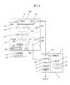
図1から図6を参照して、第1の実施形態にかかる生体情報読取装置および生体情報読取方法について説明する。図1は、第1の実施形態にかかる生体情報読取システム全体を示すシステム構成図である。図2は、第1の実施形態に係る生体情報読取システムの装置ブロック図である。図3は、第1の実施形態に係る生体情報読取装置における指静脈ユニットの動作状態を示す図であり、図3(a)が外観図、図3(b)が上下方向の動作状態を示す図、図3(c)が左右方向の動作状態を示す図である。図4は、第1の実施形態に係る生体情報読取装置の使用状態を示す図であり、図4(a)が指静脈ユニットに置かれた指を左右方向に動かした状態を示す図、図4(b)が指静脈ユニットに置かれた指を上下方向に動かした状態を示す図である。図5は、第1の実施形態に係る生体情報読取システムの動作フロー図である。図6は、第1の実施形態に係る生体情報読取システムの動作中の画面を示す図である。Hereinafter, embodiments of the present invention will be described with reference to FIGS. Here, FIGS. 1 to 8 show the first embodiment, FIGS. 9 to 13 show the second embodiment, and FIGS. 14 to 16 show the third embodiment. In addition, the same site | part, direction, etc. are shown with the same code | symbol, and the overlapping description is abbreviate | omitted. In each embodiment, as an example of biometric information, a case will be described in which a biometric authentication apparatus that employs a finger vein authentication method that performs authentication by acquiring a finger vein pattern as graphic information will be described.
(First embodiment)
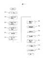
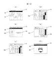
With reference to FIG. 1 to FIG. 6, a biological information reading apparatus and a biological information reading method according to the first embodiment will be described. FIG. 1 is a system configuration diagram showing the entire biological information reading system according to the first embodiment. FIG. 2 is an apparatus block diagram of the biological information reading system according to the first embodiment. 3A and 3B are diagrams showing an operation state of the finger vein unit in the biological information reading apparatus according to the first embodiment. FIG. 3A is an external view and FIG. 3B is an operation state in the vertical direction. FIG. 3 (c) is a diagram showing an operation state in the left-right direction. FIG. 4 is a diagram illustrating a usage state of the biological information reading apparatus according to the first embodiment, and FIG. 4A is a diagram illustrating a state in which a finger placed on the finger vein unit is moved in the left-right direction. FIG. 4B is a diagram illustrating a state in which a finger placed on the finger vein unit is moved in the vertical direction. FIG. 5 is an operation flowchart of the biological information reading system according to the first embodiment. FIG. 6 is a diagram illustrating a screen during operation of the biological information reading system according to the first embodiment.
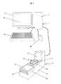
まず、図1を参照して、第1の実施形態にかかる生体情報読取システムの概略構成を説明する。図1において、この生体情報読取システムは、情報処理装置1と、この情報処理装置1とコードを介して接続される生体情報読取装置10とから構成されている。 First, a schematic configuration of a biological information reading system according to the first embodiment will be described with reference to FIG. In FIG. 1, the biological information reading system includes an
情報処理装置1は、主に生体情報の登録作業や認証作業を行うものであり、制御部や記部などを備えた情報処理装置本体2と、この情報処理装置本体2に接続される表示装置3と、キーボード4aやマウス4b等の入力装置4を含んで構成される。また、表示装置3は、タッチパネル式の表示画面3aを備えている。 The
生体情報読取装置10は、主に利用者が生体情報の登録や、生体認証を行う際に使用するものであり、情報読取装置本体20と、生体情報の読み取りを行う生体情報読取ユニット(指静脈ユニット30)と、指静脈ユニット30を駆動させる駆動装置40と、ICカード等の携帯型記録媒体に記録された個人情報の読み取りや、ICカード等の携帯型記録媒体に登録する指静脈パターンの書き込みを行うカードリーダ/ライタ50とを備えている。 The biometric
情報読取装置本体20は、カードリーダ/ライタ50に対して、ICカード等の携帯型記録媒体の出し入れを行う媒体口21と、暗証番号等の入力を行うテンキーを覆うテンキーカバー22と、本人確認を行うカメラ部23とを備えている。 The information reading device
この生体情報読取システムの大きな特徴は、照合用の指静脈パターンを取得する際に、指が置かれた指静脈ユニット30を動かして、生体認証時に認証エラーが起こりうる可能性のある複数の指姿勢の画像を撮影し、この複数の指姿勢の画像を照合用の指静脈パターンとして記録(登録)する点にある。具体的には、照合用の指静脈パターンを取得する際に、指静脈ユニット30の指置き部31を駆動装置40により上下方向や左右方向へ動かすことにより、複数の指姿勢、例えば、指の先端や根元が浮いた状態の指静脈パターンや、左右に回転した状態の指静脈パターンを取得し、取得した指静脈パターン画像を画像処理し、照合用の指静脈パターンとしてICカード等の携帯型記録媒体に登録する点に特徴がある。 A major feature of this biometric information reading system is that when acquiring a finger vein pattern for verification, the
このような構成とすることにより、生体認証時に指認証ユニットで取得した認証用の指静脈パターンと、予め登録された照合用の指静脈パターンとの照合時における誤差を小さくすることができるので、生体認証をスムーズに行うことができる。 By adopting such a configuration, it is possible to reduce an error in matching between the finger vein pattern for authentication acquired by the finger authentication unit at the time of biometric authentication and the finger vein pattern for matching registered in advance. Biometric authentication can be performed smoothly.
次に、図2を参照して、第1の実施形態にかかる生体情報読取システムの装置構成について説明する。 Next, an apparatus configuration of the biological information reading system according to the first embodiment will be described with reference to FIG.
図2において、指認証ユニット30は、登録する指を置く指置き部31と、指置き部31に置かれた指の静脈パターンを撮影する撮影部32と、指置き部31に指が置かれたか否かを検知するセンサ(図示省略)と、撮影部32で撮影された指静脈パターン画像の画像処理や、画像処理された指静脈パターンの登録、登録された指静脈パターンと認証用の指静脈パターンとの照合等を行う認証処理部33と、指置き部31を駆動させるモーター34と、撮影部32で撮影された指静脈パターン画像を保存する画像キャプチャーボード35を備えている。また、撮影部32は、光学フィルタ321と、CCDカメラ322やミラー(図示省略)等からなる光学ユニットと、指置き部31に置かれた指に対して、光学フィルタ321を介して光を照射する光源323とを備えている。 In FIG. 2, the
認証処理部33は、照合用の指静脈パターンや、生体認証時に読み取った認証用の指静脈パターンを保存するメモリ201と、指認証ユニット30の全体を制御するCPU202と、各装置を接続するためのインタフェース(I/F)203を備えている。また、認証処理部33には、外部サーバ等の外部記憶装置210やカードリーダ/ライタ50、情報処理装置本体2が接続されている。 The
モーター34は、指静脈ユニット30の指置き部31を動かす駆動装置40を構成するものであり、モーター34は、情報処理装置本体2の制御部9により、指置き部31を上下方向あるいは左右方向へ回転させるように制御される。 The
情報処理装置本体2は、各種の情報格納する記憶部6と、各種の情報を表示する表示部3と、ネットワークと接続するための通信部7と、キーボード4aやマウス4bとで構成される入力部4と、この情報処理装置2を統括的に制御する制御部9と、各装置を接続するためのインタフェース(I/F)250とを含んで構成される。 The information processing apparatus
この生体情報読取システムは、指置き部31に指が置かれたことをセンサで検知すると、撮影部32を介して指静脈パターンを撮影し、撮影した指静脈パターンの画像を画像キャプチャーボード35に保存する。そして、CPU202により指静脈画像の登録操作が指示されると、画像キャプチャーボード35に保存された指静脈パターンの画像がインタフェース203を介して認証処理部33に送られるとともに画像処理が行なわれ、照合用の指静脈パターンとしてメモリ201に記録されるようになっている。メモリ201に記録された照合用の指静脈パターンは、インタフェース203を介してカードリーダ/ライタ50に挿入されたICカードに記録することができるようになっている。なお、照合用の指静脈パターンは、例えば、銀行に設置されるサーバ等の外部記憶装置210に記録するようにしてもよい。 When this biometric information reading system detects that a finger is placed on the
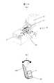
次に、図3を参照して、第1の実施形態にかかる生体情報読取システムにおける読取装置の動作について説明する。 Next, the operation of the reading device in the biological information reading system according to the first embodiment will be described with reference to FIG.
図3(a)において、指置き部31は、その短手方向の延長軸線P1および長手方向の延長軸線Q1に沿って、モーター34を介して上下方向(矢印Aの方向)および左右方向(矢印Bの方向)へ回転するように、制御部9で制御される。具体的には、図3(b)で示すように、上下方向への回転は、回転軸Pを中心としてモーター34により指置き部31を矢印Aの方向へ回転するように制御部9で制御される構成となっている。また、図3(c)で示すように、左右方向への回転は回転軸Qを中心としてモーター34により指置き部31を矢印Bの方向へ回転させるように制御部9で制御される構成となっている。
このような構成とすることにより、指認証ユニット30に指を置いた利用者が指を動かすことなく、指の先端や根元が浮いた状態の指静脈パターン画像、左右に回転した状態の指静脈パターン画像等を取得することができる。なお、この実施形態では、指置き部31の回転方向を、生体情報読取装置10の正面(媒体口21が配置された面)を基準として特定している。In FIG. 3 (a), the
With such a configuration, the finger vein pattern image in which the tip or root of the finger is lifted without the user placing the finger on the
次に、図4から図6を参照して、照合用の認証データである指静脈パターンの登録動作について説明する。 Next, with reference to FIGS. 4 to 6, a registration operation of a finger vein pattern which is authentication data for verification will be described.
まず、指静脈パターンを登録する利用者は、係員に指示に従って、ICカードを媒体口21からカードリーダ/ライタ50に挿入し(ステップ501)、テンキーカバー22を開けてテンキーにより暗証番号を入力してICカードの読み込みを行う。 First, a user who registers a finger vein pattern inserts an IC card into the card reader /
ICカードの読み込みが完了すると、係員は表示装置3に表示される図6(a)で示すような指登録画面60を見ながら、利用者に対して登録する指について口頭で質問する(ステップ502)。利用者は、係員からの質問に対して登録する指を決定し、決定した指を係員に口頭で伝える(ステップ503)。係員は、利用者からの回答に基づき、登録する指を読取装置30へ置くように利用者へ口頭で伝え(ステップ504)、利用者は係員の指示に従って読取装置30に登録する指を置く(ステップ505)。 When the reading of the IC card is completed, the clerk asks the user verbally about the finger to be registered while looking at the
係員は、指静脈ユニット30の指置き部31に指が置かれたことを確認すると、表示装置3の表示画面3aに表示された図6(b)で示すような撮影操作画面62の撮影ボタンを操作するとともに(ステップ506)、利用者に対して正面の指静脈パターン画像の撮影中であることを口頭で伝える(ステップ507)。 When the clerk confirms that the finger is placed on the
正面の指静脈パターン画像の撮影が終了すると、係員は表示画面3aに表示される図6(c)で示すような撮影操作画面62を見ながら、利用者に対して指の回転画像を撮影することを伝えると共に、指認証ユニット30(指置き部31)が動くことを伝える(ステップ508)。そして、撮影操作画面62に表示された撮影ボタンを操作することにより(ステップ509)、図4で示すように、指が置かれた指置き部31を、上下方向(矢印Aの方向)および左右方向(矢印Bの方向)に動かし、登録する指の回転画像を撮影する(ステップ510)。この時、表示装置3の表示装置3aには、図6(d)および図6(e)で示すような撮影操作画面62が、撮影姿勢に合わせて表示されるようになっている。 When the photographing of the finger vein pattern image on the front is completed, the clerk shoots a finger rotation image while viewing the photographing
ステップ511において、係員は照合用の指静脈パターンの登録に必要な指静脈パターン画像が全て撮影されたことを確認すると、利用者に対して撮影が終了したことを伝えるとともに、指認証ユニット30から指を離すように伝え、利用者は係員の指示に従って指認証ユニット30から指を離す(ステップ512)。係員は、利用者が指静脈ユニット30から指を離したことを確認すると、表示装置3の表示画面3aに表示される図6(f)で示すような撮影終了画面63を見ながら、カード書き込みボタン64を操作して(ステップ513)、照合用の指静脈パターンの書き込み作業に入る(ステップ514)。 In
指静脈パターンの書き込みが終了したら、係員は表示装置3の表示画面3aに表示される図6(g)で示すような終了画面65を見ながら、利用者に対しての書き込み(登録)が終了したこと、およびICカードを取るように伝える。そして、利用者が媒体口21から排出されたICカードを取ることにより(ステップ515)、一連の動作が終了する。 When the writing of the finger vein pattern is completed, the attendant finishes writing (registration) to the user while viewing the
なお、ステップ511において、登録に必要な指静脈パターン画像が全て撮影されていない場合には、ステップ509からステップ510の動作を繰り返し、登録に必要な全ての指静脈パターン画像を撮影する。そして、指静脈パターン画像の撮影が終了したら、照合用の指静脈パターンの書き込み作業(ステップ513からステップ515の動作)に入るようになっている。 In
この実施形態では、表示装置3の表示画面3aに表示される各画面に、係員が利用者を誘導するガイダンスや、係員の行動に関するガイダンス等を表示するガイダンス表示エリア61を設けたことに特徴がある。また、利用者に伝えるガイダンスと係員の行動に関するガイダンスとを、ガイダンス表示エリア61で分けて表示することに特徴がある。具体的には、図6で示すように、利用者に伝えるガイダンスについてはフォーカス68を当てて目立つようにしている。これにより、係員は利用者をスムーズに誘導することができる。 This embodiment is characterized in that each screen displayed on the
次に、図7および図8を参照して、第1の実施形態にかかる生体情報読取装置および生体情報読取方法の応用例について説明する。 Next, application examples of the biological information reading apparatus and the biological information reading method according to the first embodiment will be described with reference to FIGS.
図7は、第1の実施形態に係る生体情報読取装置における指認証ユニットの動作状態の応用例を示す図であり、図7(a)が外観図、図7(b)が水平方向の動作状態を示す図ある。図8は、第1の実施形態に係る認証装置の使用状態の応用例を示す図であり、図8(a)が指置き部に置かれた指を水平右方向に動かした状態を示す図、図8(b)が指置き部に置かれた指を水平左方向に動かした状態を示す図である。 7A and 7B are diagrams showing an application example of the operation state of the finger authentication unit in the biometric information reading apparatus according to the first embodiment. FIG. 7A is an external view, and FIG. 7B is a horizontal operation. It is a figure which shows a state. FIG. 8 is a diagram illustrating an application example of the usage state of the authentication device according to the first embodiment, and FIG. 8A is a diagram illustrating a state in which the finger placed on the finger placement unit is moved in the horizontal right direction. FIG. 8B is a diagram illustrating a state in which the finger placed on the finger placement unit is moved in the horizontal left direction.
図7および図8において、この実施形態では、指認証ユニット30を上下方向および左右方向への動作に加え、水平方向(矢印Cの方向)へ動作させる構成、即ち、指認証ユニット30を3方向へ回転させることができるような構成に特徴を有している。 7 and 8, in this embodiment, the
具体的には、図7で示すように、指置き部31は回転軸Sを中心として、水平方向(矢印Cの方向)へモーター34を介して回転できるようになっている。そして、図8で示すように、指が置かれた指置き部31を矢印Cの方向、即ち、生体情報読取装置10の上面に対して水平方向へ回転させることにより、水平左方向および水平右方向に傾いた状態の指静脈パターン画像を撮影する。 Specifically, as shown in FIG. 7, the
このような構成とすることにより、上下方向および左右方向の指静脈パターン画像に加え、水平方向の指静脈パターン画像も照合用の指静脈パターンとして登録することができるので、生体認証時における認証精度を更に向上させることができ、生体認証をスムーズに行うことができる。 By adopting such a configuration, in addition to the vertical and horizontal finger vein pattern images, the horizontal finger vein pattern image can be registered as a finger vein pattern for verification. Can be further improved, and biometric authentication can be performed smoothly.
なお、図7および図8において、生体情報読取システムおよび生体情報読取装置の構成、および照合用の指静脈パターンの撮影や登録方法等については、上述した図1から図6の説明と同一であるため、詳細な説明は省略する。
以上述べたように、本発明の第1の実施形態では、指置き部31を駆動装置40(モーター34)により複数の方向へ動かすことができる構成に大きな特徴がある。そして、このような構成とすることにより、様々な姿勢における指静脈パターンを照合用の指静脈パターンとして登録することができる。しかも、生体認証時においては、認証用の指静脈パターンを、登録した多数の指静脈パターンと照合することが出きるから、誤差の少ない正確な認証を行うことができる。
(第2の実施の形態)
次に、図9から図13を参照して、第2の実施形態にかかる生体情報読取装置および生体情報読取方法について説明する。7 and 8, the configurations of the biometric information reading system and the biometric information reading device, and the method for capturing and registering the finger vein pattern for verification are the same as those described above with reference to FIGS. Therefore, detailed description is omitted.
As described above, the first embodiment of the present invention has a great feature in the configuration in which the
(Second Embodiment)
Next, a biological information reading apparatus and a biological information reading method according to the second embodiment will be described with reference to FIGS.
図9は、第2の実施形態に係る生体情報読取システムの装置ブロック図である。図10は、第2の実施形態に係る生体情報読取装置における指認証ユニットの動作状態を示す図であり、図10(a)が外観図、図10(b)が上下方向の動作状態を示す図、図10(c)が左右方向の動作状態を示す図である。図11は、第2の実施形態に係る生体情報読取システムの動作フロー図である。図12は、第2の実施形態に係る生体情報読取システムの動作中の画面を示す図である。 FIG. 9 is an apparatus block diagram of the biological information reading system according to the second embodiment. FIG. 10 is a diagram illustrating an operation state of the finger authentication unit in the biometric information reading apparatus according to the second embodiment. FIG. 10A is an external view, and FIG. 10B illustrates an operation state in the vertical direction. FIG. 10 (c) is a diagram showing an operation state in the left-right direction. FIG. 11 is an operation flowchart of the biological information reading system according to the second embodiment. FIG. 12 is a diagram illustrating a screen during operation of the biological information reading system according to the second embodiment.
図9において、第2の実施形態に係る指静脈ユニット30aは、登録する指を置く指置き部31と、指置き部31に置かれた指の静脈パターンを撮影する撮影部32と、指置き部31に指が置かれたか否かを検知するセンサ(図示省略)と、撮影部32で撮影された指静脈パターン画像の画像処理や、画像処理された指静脈パターンの登録、登録された指静脈パターンと認証を行う指静脈パターンとの照合等を行う認証処理部33と、撮影部32で撮影された指静脈パターン画像を保存する画像キャプチャーボード35を備えている。また、撮影部32は、光学フィルタ321と、CCDカメラ322やミラー325(図10参照)等からなる光学ユニット327と、指置き部31に置かれた指に対して、光学フィルタ321を介して光を照射する光源323とを備えている。 In FIG. 9, the
この第2の実施形態に係る生体情報読取システムは、CCDカメラ322やミラー325等からなる光学ユニット327を上下方向および左右方向へ動かすモーター34を、指静脈ユニット30aに設けた点にある。具体的には、図10(b)で示すように、上下方向への回転は、回転軸Pを中心としてモーター34により光学ユニット327を矢印Aの方向へ回転するように制御部9で制御される構成となっている。また、図10(c)で示すように、左右方向への回転は回転軸Qを中心としてモーター34により光学ユニット327を矢印Bの方向へ回転させるように制御部9で制御される構成となっている。 The biological information reading system according to the second embodiment is that a
なお、図9および図10において、その他の構成については、第1の実施形態と同一であるため、詳細な説明は省略する。 9 and 10, other configurations are the same as those in the first embodiment, and thus detailed description thereof is omitted.
次に、図11および図12を参照して、指静脈パターンの登録動作について説明する。図11において、ステップ501からステップ505の動作については、第1の実施形態と同一であるため、詳細な説明は省略する。図11において、係員は表示装置3の表示画面3aに表示される図12(b)で示すような撮影操作画面62aを見ながら、利用者に対して、複数の指静脈パターン画像を撮影するのでそのまま待つように口頭で伝える(ステップ701)。次に、係員は撮影ボタン66を操作し(ステップ702)、指静脈パターン画像の自動撮影を開始する(ステップ703)。なお、指静脈パターン画像の撮影中は、表示装置3の表示画面3aに図12(c)および図12(d)で示すような撮影操作画面62aが表示されるようになっている。また、撮影操作画面62aのガイダンス表示エリア61には、自動撮影の進捗状況が表示されるようになっている。 Next, a finger vein pattern registration operation will be described with reference to FIGS. In FIG. 11, the operations from
ステップ704において、指静脈パターン画像の自動撮影が終了すると、係員は表示装置3の表示画面3aに表示される図12(e)で示すような撮影終了画面63aを見ながら、利用者に対して指静脈パターン画像の自動撮影が終了したことを伝え、利用者に指静脈ユニット30aから指を離すように促す(ステップ512)。そして、係員は、利用者が指静脈ユニット30aから指を離したことを確認すると、照合用の指静脈パターンの登録作業に入る。なお、照合用の指静脈パターンの登録作業については、第1の実施形態におけるステップ513からステップ515の動作と同一であるため、詳細な説明は省略する。 In
次に、図13を参照して、第2の実施形態にかかる生体情報読取装置および生体情報読取方法の応用例について説明する。 Next, an application example of the biological information reading apparatus and the biological information reading method according to the second embodiment will be described with reference to FIG.
図13は、第2の実施形態に係る生体情報読取装置における指静脈ユニットの動作状態の応用例を示す図であり、図13(a)が外観図、図13(b)が水平方向の動作状態を示す図ある。 FIG. 13 is a diagram illustrating an application example of the operation state of the finger vein unit in the biological information reading apparatus according to the second embodiment. FIG. 13A is an external view, and FIG. 13B is a horizontal operation. It is a figure which shows a state.
図13において、この実施形態では、モーター34により光学ユニット327を上下方向および左右方向へ動作させる構成に加え、水平方向(矢印Cの方向)へ動作させる構成、即ち、光学ユニット327を3方向へ回転させることができるような構成に特徴を有している。具体的には、光学ユニット327が回転軸Sを中心として、水平方向(矢印Cの方向)へモーター34を介して回転できるようになっている。そして、光学ユニット327を水平右方向および水平左方向へ回転させることにより、水平方向の左右に傾いた状態の指静脈パターン画像を撮影する。 In FIG. 13, in this embodiment, in addition to a configuration in which the
これにより、第1の実施形態と同様、上下方向および左右方向の画像に加え、水平方向の指静脈パターン画像も照合用の指静脈パターン画像として登録することができるので、生体認証時における認証精度を更に向上させることができ、生体認証をスムーズに行うことができる。なお、本実施形態において、生体情報読取システムの構成、および照合用の指静脈パターン画像の撮影や登録方法等については、上述した第1の実施形態と同一であるため、詳細な説明は省略する。 Thus, as in the first embodiment, in addition to the vertical and horizontal images, the horizontal finger vein pattern image can also be registered as a finger vein pattern image for verification. Can be further improved, and biometric authentication can be performed smoothly. In this embodiment, the configuration of the biometric information reading system and the method for capturing and registering a finger vein pattern image for verification are the same as those in the first embodiment described above, and detailed description thereof is omitted. .
以上述べたように、この第2の実施形態では、光学ユニット327を駆動装置40(モーター34)により複数の方向へ動かすことができる構成に大きな特徴がある。そして、このような構成とすることにより、第1の実施形態と同様、様々な姿勢における指静脈パターンを照合用データとして登録することができる。しかも、この第2の実施形態においては、指静脈ユニット30の内部に配置された光学ユニットが自動的に動くので、指接触部に指を置いた利用者に対する負担を軽減することができる。
(第3の実施の形態)
次に、図14から図16を参照して、第3の実施形態にかかる生体情報読取装置および生体情報読取方法について説明する。As described above, the second embodiment is greatly characterized in that the
(Third embodiment)
Next, a biological information reading apparatus and a biological information reading method according to the third embodiment will be described with reference to FIGS.
図14は、第3の実施形態に係る生体情報読取システムの装置ブロック図である。図15は、第3の実施形態に係る生体情報読取システムの動作フロー図である。図16は、第3の実施形態に係る生体情報読取システムの動作中の画面を示す図である。なお、本実施形態において、生体情報読取システムの構成については、上述した第1の実施形態と同一であるため、詳細な説明は省略する。 FIG. 14 is an apparatus block diagram of a biological information reading system according to the third embodiment. FIG. 15 is an operation flowchart of the biological information reading system according to the third embodiment. FIG. 16 is a diagram illustrating a screen during operation of the biological information reading system according to the third embodiment. In the present embodiment, the configuration of the biological information reading system is the same as that of the first embodiment described above, and thus detailed description thereof is omitted.
図14において、第3の実施形態に係る指静脈ユニット30bは、上述した第2の実施形態に係る指静脈ユニット30aに、記憶装置207と画像コントローラ208とを追加したことに特徴がある。具体的には、制御部9から照合用の指静脈パターンの登録処理が指示されると、CPU202は画像コントローラ208を制御して、メモリ201および記憶装置207に記憶された撮影データの中から、例えば、上下浮きの画像や左右の曲がり画像等を抽出し、複数の照合用の指静脈パターンを、プログラムによる画像編集で生成するようになっている。このような構成とすることにより、撮影された画像から複数の照合用の指静脈パターンを生成するので、指静脈パターンの登録時におけるユーザーの負担を更に軽減させることができる。 In FIG. 14, the
次に、図15および図16を参照して、指静脈パターンの登録動作について説明する。図15において、ステップ501からステップ505の動作については、第1の実施形態と同一であるため、詳細な説明は省略する。図15において、係員は表示装置3の表示画面3aに表示された図16(b)で示すような撮影操作画面62bを見ながら撮影ボタンを操作し(ステップ801)、1本目の指静脈パターン画像の撮影を開始する(ステップ802)。 Next, a finger vein pattern registration operation will be described with reference to FIGS. 15 and 16. In FIG. 15, operations from
ステップ803において、1本目の指静脈パターン画像の撮影が終了したら、2本目以降の指静脈パターンの画像が必要かを判断する。判断の結果、2本目以降の指の画像が必要な場合は、ステップ801からステップ803の動作を、必要な画像の撮影が完了するまで繰り返す。この時、表示装置3の表示画面3aには、図16(c)で示すような撮影操作画面62bが表示されるようになっている。 In
ステップ803において、必要な指静脈パターン画像の撮影が完了したら、係員は利用者に対して指静脈パターン画像の撮影が終了したことを伝え、利用者に指静脈ユニット30bから指を離すように促す(ステップ804)。この時、表示装置3の表示画面3aには、図16(d)で示すような登録処理開始画面67が表示されており、係員は、利用者が指静脈ユニット30bから指を離したことを確認すると、登録処理開始ボタン70を操作して多パターン画像の自動生成を開始する(ステップ806)。そして、多パターン画像の生成が終了すると、登録の準備ができたことを利用者に伝える(ステップ807)。この時、表示装置3の表示画面3aには、図16(e)で示すような書き込み開始画面69が表示され、係員が書き込みボタン64を操作することにより、照合用の指静脈パターンの書き込み作業に入る。なお、書き込み作業については、第1の実施形態におけるステップ513からステップ515の動作と同一であるため、詳細な説明は省略する。 In
以上のように、この第3の実施形態では、1つの撮影データから複数の照合用の指静脈パターン、即ち、認証エラーが発生する可能性のある指静脈パターンを自動的に生成して登録するので、利用者が指静脈ユニットに指を置いておく時間を短くすることができ、生体情報の登録時における利用者の負担を更に軽減することができる。 As described above, in the third embodiment, a plurality of finger vein patterns for verification, that is, finger vein patterns that may cause an authentication error are automatically generated and registered from one imaged data. Therefore, it is possible to shorten the time for the user to place the finger on the finger vein unit, and to further reduce the burden on the user when registering the biometric information.
1…情報処理装置、2…情報処理装置本体、3…表示装置、3a…表示画面、4…入力装置、4a…キーボード、4b…マウス、6…記憶部、7…通信部、9…制御部、10…生体認証装置、20…認証装置本体、21…媒体口、22…テンキーカバー、23…カメラ部、30…指静脈ユニット、31…指置き部、32…撮影部、33…認証処理部、34…モーター、35…画像キャプチャーボード、40…駆動装置、50…カードリーダ/ライタ、60…指登録画面、61…ガイダンス表示エリア、62…撮影操作画面、63…撮影終了画面、64…カード書き込みボタン、65…終了画面、66…撮影ボタン、67…登録処理開始画面、68…フォーカス、70…登録処理開始ボタン、201…メモリ、202…CPU、203…インタフェース、207…記憶装置、208…画像コントローラ、210…外部記憶装置、250…インタフェース、321…光学フィルタ、322…CCDカメラ、323…光源、325…ミラー、327…光学ユニット。DESCRIPTION OF
Claims (7)
Translated fromJapanese前記生体情報読取ユニットは、生体が設置される生体接触部と、前記生体接触部に設置された生体の画像を撮影する撮影部と、前記生体接触部をその設置面に対して上下方向および左右方向へ回転させる駆動装置と、撮影された生体の画像を画像処理する処理装置を備え、
前記駆動装置は、前記生体接触部を、その短手方向に沿って設けられた第1回転軸を介して前記上下方向へ回転させるとともに、その長手方向に沿って設けられた第2回転軸を介して前記左右方向へ回転させ、
前記撮影部は、前記生体接触部の回転方向に対応して複数の画像を撮影し、
前記処理装置は、撮影された前記複数の画像をそれぞれ照合用の生体情報として登録するための処理を実行し、
前記処理装置により処理された前記複数の画像を、前記情報読取書込装置に挿入された記録媒体にそれぞれ照合用の生体情報として記録する
ことを特徴とする生体情報読取装置。In a biological information reading apparatus comprising a biological information reading unit that acquires biological information and processes the acquired biological information, and an information reading / writing device that writes and reads the biological information.
The living body information reading unit includes a living body contact unit in which a living body is installed, an imaging unit that takes an image of the living body installed in the living body contact unit, and the biological contact unit inthe vertical direction and the left and right directions with respect tothe installation surface A driving device thatrotates in adirection, and a processing device that performs image processing on a captured biological image,
The drive devicerotates the living body contact portion in theup and down direction via a first rotation axis provided along the short direction, and a second rotation axis provided along the longitudinal direction. Through the left and right direction,
The imaging unit capturesa plurality of imagescorresponding to therotation direction of the living body contact unit,
Wherein the processing unit executes a process for registering a plurality ofimages taken as the biometric information for matching, respectively,
The biometric information reading device, wherein the plurality of images processed by the processing device are recorded as biometric information for collation on a recording medium inserted in the information reading / writing device.
前記駆動装置は、さらに前記生体接触部を、その設置面に対して垂直に設けられた第3回転軸を介して水平方向へ回転させる
ことを特徴とする生体情報読取装置。The biological information reader according to claim 1,
The driving apparatus further the biological contact portion, the biometric information reading apparatus characterized by causingrotation in the horizontal directionthrough the third rotation shaft disposed perpendicular to its installation surface.
前記生体情報読取ユニットは、生体が設置される生体接触部と、前記生体接触部に設置された生体の画像を撮影する撮影部と、前記撮影部を前記生体接触部の設置面に対して上下方向および左右方向へ回転させる駆動装置と、撮影された生体の画像を画像処理する処理装置を備え、
前記撮影部は、前記生体接触部に設置された生体の画像をその動作方向に合わせて複数の画像を撮影するための光源と光学ユニットとを備え、
前記駆動装置は、前記光学ユニットを、前記生体接触部の短手方向に沿って設けられた第1回転軸を介して前記上下方向へ回転させるとともに、前記生体接触部の長手方向に沿って設けられた第2回転軸を介して前記左右方向へ回転させ、
前記処理装置は、撮影された前記複数の画像をそれぞれ照合用の生体情報として登録するための処理を実行し、
前記処理装置により処理された前記複数の画像を、前記情報読取書込装置に挿入された記録媒体にそれぞれ照合用の生体情報として記録する
ことを特徴とする生体情報読取装置。In a biological information reading apparatus comprising a biological information reading unit that acquires biological information and processes the acquired biological information, and an information reading / writing device that writes and reads the biological information.
The living body information reading unit includes a living body contact unit on which a living body is installed, an imaging unit that captures an image of the living body installed on the living body contact unit, and the imaging unit that is positioned above and below the installation surface of the living body contact unit. A driving device that rotates in a horizontal direction and a horizontal direction, and a processing device that performs image processing on a captured biological image,
The photographing unit includes a light source and an optical unit for photographing a plurality of imagesaccording to an operation direction of an image of a living body installed on the living body contact unit,
The drive devicerotates the optical unit in thevertical direction via a first rotation shaft provided along theshort direction of the biological contact portion, and is provided along the longitudinal direction of the biological contact portion. Rotated in the left-right direction via the second rotation axis
The processing device executes processing for registering the captured images as biometric information for verification,
The biometric information reading device, wherein the plurality of images processed by the processing device are recorded as biometric information for collation on a recording medium inserted in the information reading / writing device.
前記駆動装置は、さらに前記光学ユニットを、前記生体接触部の設置面に対して垂直に設けられた第3回転軸を介して水平方向へ回転させる
ことを特徴とする生体情報読取装置。The biological information reader according to claim 3.
The driving device further wherein the optical unit, the biological contact portion biometric information reading apparatus characterized by causingrotation in the horizontal directionthrough the third rotation shaft disposed perpendicular to the installation surface of the.
前記情報処理装置は、前記生体情報読取システムを統括的に制御する制御装置を備え、
前記生体情報読取装置は、生体情報を取得するとともに、取得した生体情報を処理する生体情報読取ユニットと、前記生体情報の書き込みや読み取りを行う情報読取書込装置とを備え、
前記生体情報読取ユニットは、生体が設置される生体接触部と、前記生体接触部に設置された生体の画像を撮影する撮影部と、前記生体接触部をその設置面に対して上下方向および左右方向へ回転させる駆動装置と、撮影された生体の画像を画像処理する処理装置とを備え、
前記駆動装置は、前記制御部からの動作信号を受け付けると、前記生体接触部を、その短手方向に沿って設けられた第1回転軸を介して前記上下方向へ回転させるとともに、その長手方向に沿って設けられた第2回転軸を介して前記左右方向へ回転させ、
前記撮影部は、前記生体接触部の回転方向に合わせて複数の画像を撮影し、
前記処理装置は、前記複数の画像をそれぞれ照合用の生体情報として登録するための処理を実行し、
前記処理装置により処理された前記複数の画像を、前記情報読取書込装置に挿入された記録媒体にそれぞれ照合用の生体情報として記録する
ことを特徴とする生体情報登録システム。In a biological information reading system provided with an information processing device and a biological information reading device,
The information processing apparatus includes a control device that comprehensively controls the biological information reading system,
The biometric information reading device includes a biometric information reading unit that acquires biometric information and processes the acquired biometric information, and an information reading / writing device that writes and reads the biometric information.
The living body information reading unit includes a living body contact unit on which a living body is installed, an imaging unit that captures an image of the living body installed on the living body contact unit,and a vertical direction and a left and right direction of the living body contact unit withrespect tothe installation surface. A driving device thatrotates in adirection, and a processing device that performs image processing on a captured biological image,
When the driving device receives the operation signal from the control unit, the driving devicerotates the living body contact unit in thevertical direction via a first rotation shaft provided along the short direction, and the longitudinal direction thereof. Through the second rotating shaft provided along the left and right direction,
The imaging unit captures a plurality of images according to therotation direction of the living body contact unit,
The processing device executes processing for registering the plurality of images as biometric information for verification,
The biometric information registration system, wherein the plurality of images processed by the processing device are recorded as biometric information for verification on a recording medium inserted in the information reading / writing device, respectively.
前記情報処理装置は、前記生体情報読取システムを統括的に制御する制御装置を備え、
前記生体情報読取装置は、生体情報を取得するとともに、取得した生体情報を処理する生体情報読取ユニットと、前記生体情報の書き込みや読み取りを行う情報読取書込装置とを備え、
前記生体情報読取ユニットは、生体が設置される生体接触部と、前記生体接触部に設置された生体の画像を撮影する撮影部と、前記撮影部を前記生体接触部の設置面に対して上下方向および左右方向へ回転させる駆動装置と、撮影された生体の画像を画像処理する処理装置とを備え、
前記撮影部は、前記生体接触部に設置された生体の画像をその回転方向に合わせて複数撮影するための光源と光学ユニットとを備え、
前記駆動装置は、前記制御部からの動作信号を受け付けると、前記光学ユニットを、その短手方向に沿って設けられた第1回転軸を介して前記上下方向へ回転させるとともに、その長手方向に沿って設けられた第2回転軸を介して前記左右方向へ回転させ、
前記処理装置は、前記複数の画像をそれぞれ照合用の生体情報として登録するための処理を実行し、
前記処理装置により処理された前記複数の画像を、前記情報読取書込装置に挿入された記録媒体にそれぞれ照合用の生体情報として記録する
ことを特徴とする生体情報登録システム。In a biological information reading system provided with an information processing device and a biological information reading device,
The information processing apparatus includes a control device that comprehensively controls the biological information reading system,
The biometric information reading device includes a biometric information reading unit that acquires biometric information and processes the acquired biometric information, and an information reading / writing device that writes and reads the biometric information.
The living body information reading unit includes a living body contact unit on which a living body is installed, an imaging unit that captures an image of the living body installed on the living body contact unit, and the imaging unit that is positioned above and below the installation surface of the living body contact unit. A driving device that rotates in a horizontal direction and a horizontal direction, and a processing device that performs image processing on a captured biological image,
The photographing unit includes a light source and an optical unit for photographing aplurality of images of a living body installed on the living body contact unitin accordance with a rotation direction thereof ,
When the driving device receivesan operation signal from the control unit , the driving devicerotates the optical unit in thevertical direction via a first rotation shaft provided along the short direction, and in the longitudinal direction. Rotating in the left-right direction via a second rotating shaft provided along the
The processing device executes processing for registering the plurality of images as biometric information for verification,
A biometric information registration system thatrecords the plurality of images processed by the processing device as biometric information for collation on a recording medium inserted in the information reading / writing device .
前記生体情報登録システムは、表示装置を備え、
前記表示装置には、生体登録画面と、撮影操作画面と、撮影終了画面と、登録終了画面とが表示され、
前記各画面には、その上端に係員の操作に対するガイダンスと、利用者の動作を誘導するガイダンスを表示するガイダンス表示エリアが配置されている
ことを特徴とする生体情報登録システム。The biological information reading system according to claim 5 or 6,
The biometric information registration system includes a display device,
The display device displays a biometric registration screen, a shooting operation screen, a shooting end screen, and a registration end screen.
Each of the screens is provided with a guidance display area for displaying guidance for an operation of an attendant and guidance for guiding a user's operation at the upper end of each screen.
Priority Applications (1)
| Application Number | Priority Date | Filing Date | Title |
|---|---|---|---|
| JP2007090208AJP4857164B2 (en) | 2007-03-30 | 2007-03-30 | Biological information reader and biological information reading system |
Applications Claiming Priority (1)
| Application Number | Priority Date | Filing Date | Title |
|---|---|---|---|
| JP2007090208AJP4857164B2 (en) | 2007-03-30 | 2007-03-30 | Biological information reader and biological information reading system |
Publications (2)
| Publication Number | Publication Date |
|---|---|
| JP2008250601A JP2008250601A (en) | 2008-10-16 |
| JP4857164B2true JP4857164B2 (en) | 2012-01-18 |
Family
ID=39975486
Family Applications (1)
| Application Number | Title | Priority Date | Filing Date |
|---|---|---|---|
| JP2007090208AExpired - Fee RelatedJP4857164B2 (en) | 2007-03-30 | 2007-03-30 | Biological information reader and biological information reading system |
Country Status (1)
| Country | Link |
|---|---|
| JP (1) | JP4857164B2 (en) |
Cited By (1)
| Publication number | Priority date | Publication date | Assignee | Title |
|---|---|---|---|---|
| US12406533B2 (en) | 2023-11-24 | 2025-09-02 | Samsung Electronics Co., Ltd. | Fingerprint enrolling method and fingerprint enrolling device |
Families Citing this family (22)
| Publication number | Priority date | Publication date | Assignee | Title |
|---|---|---|---|---|
| KR20200090943A (en) | 2007-09-24 | 2020-07-29 | 애플 인크. | Embedded authentication systems in an electronic device |
| US8600120B2 (en) | 2008-01-03 | 2013-12-03 | Apple Inc. | Personal computing device control using face detection and recognition |
| JP5399862B2 (en) | 2009-10-30 | 2014-01-29 | 富士通フロンテック株式会社 | Personal authentication / operation instruction input method, apparatus, and program using biometric information with posture information |
| CN103003840A (en)* | 2010-09-30 | 2013-03-27 | 富士通先端科技株式会社 | Registration program, registration device, and registration method |
| JP5664288B2 (en)* | 2011-01-28 | 2015-02-04 | 沖電気工業株式会社 | Biological information acquisition device |
| US8638385B2 (en) | 2011-06-05 | 2014-01-28 | Apple Inc. | Device, method, and graphical user interface for accessing an application in a locked device |
| US9002322B2 (en) | 2011-09-29 | 2015-04-07 | Apple Inc. | Authentication with secondary approver |
| US8769624B2 (en) | 2011-09-29 | 2014-07-01 | Apple Inc. | Access control utilizing indirect authentication |
| JP5655155B2 (en)* | 2011-10-27 | 2015-01-14 | 富士通フロンテック株式会社 | Information processing apparatus, information processing method, and information processing program |
| JP6036184B2 (en)* | 2012-11-01 | 2016-11-30 | 沖電気工業株式会社 | Transaction apparatus, transaction method, and transaction system |
| US9898642B2 (en) | 2013-09-09 | 2018-02-20 | Apple Inc. | Device, method, and graphical user interface for manipulating user interfaces based on fingerprint sensor inputs |
| US10043185B2 (en) | 2014-05-29 | 2018-08-07 | Apple Inc. | User interface for payments |
| DK179186B1 (en) | 2016-05-19 | 2018-01-15 | Apple Inc | REMOTE AUTHORIZATION TO CONTINUE WITH AN ACTION |
| DK179978B1 (en) | 2016-09-23 | 2019-11-27 | Apple Inc. | Image data for enhanced user interactions |
| KR102185854B1 (en) | 2017-09-09 | 2020-12-02 | 애플 인크. | Implementation of biometric authentication |
| CN117077102A (en) | 2017-09-09 | 2023-11-17 | 苹果公司 | Implementation of biometric authentication |
| US11170085B2 (en) | 2018-06-03 | 2021-11-09 | Apple Inc. | Implementation of biometric authentication |
| US10860096B2 (en) | 2018-09-28 | 2020-12-08 | Apple Inc. | Device control using gaze information |
| US11100349B2 (en) | 2018-09-28 | 2021-08-24 | Apple Inc. | Audio assisted enrollment |
| EP4264460A1 (en) | 2021-01-25 | 2023-10-25 | Apple Inc. | Implementation of biometric authentication |
| US12210603B2 (en) | 2021-03-04 | 2025-01-28 | Apple Inc. | User interface for enrolling a biometric feature |
| US12216754B2 (en) | 2021-05-10 | 2025-02-04 | Apple Inc. | User interfaces for authenticating to perform secure operations |
Family Cites Families (5)
| Publication number | Priority date | Publication date | Assignee | Title |
|---|---|---|---|---|
| JP2000148982A (en)* | 1998-11-13 | 2000-05-30 | Mitsubishi Electric Building Techno Service Co Ltd | Fingerprint collating device |
| JP4547899B2 (en)* | 2003-11-25 | 2010-09-22 | 株式会社日立製作所 | Personal authentication device |
| JP2006197981A (en)* | 2005-01-18 | 2006-08-03 | Mitsubishi Electric Corp | Fingerprint verification apparatus |
| JP2007000648A (en)* | 2005-04-22 | 2007-01-11 | Hitachi Omron Terminal Solutions Corp | Biometric authentication device, terminal device, automatic transaction device |
| JP4671027B2 (en)* | 2005-05-02 | 2011-04-13 | ソニー株式会社 | Authentication apparatus, authentication method, and program |
- 2007
- 2007-03-30JPJP2007090208Apatent/JP4857164B2/ennot_activeExpired - Fee Related
Cited By (1)
| Publication number | Priority date | Publication date | Assignee | Title |
|---|---|---|---|---|
| US12406533B2 (en) | 2023-11-24 | 2025-09-02 | Samsung Electronics Co., Ltd. | Fingerprint enrolling method and fingerprint enrolling device |
Also Published As
| Publication number | Publication date |
|---|---|
| JP2008250601A (en) | 2008-10-16 |
Similar Documents
| Publication | Publication Date | Title |
|---|---|---|
| JP4857164B2 (en) | Biological information reader and biological information reading system | |
| JP4541427B2 (en) | Biometric authentication device, biometric information registration device, and biometric authentication method | |
| EP1679666B1 (en) | Renewal method and renewal apparatus for a medium having biometric authentication functions | |
| JP4672327B2 (en) | Automatic service method, automatic service device and program thereof | |
| KR100805283B1 (en) | Biometric information registration device and method | |
| JP5213908B2 (en) | Biometric authentication unit | |
| KR20090004501A (en) | Biometric authentication processing system | |
| JP5851209B2 (en) | Biometric authentication apparatus and automatic transaction apparatus including the same | |
| JP5337431B2 (en) | Card processing apparatus and card processing method | |
| CN102467791A (en) | Biometric authentication unit, automatic transaction processing device, biometric authentication method, and biometric authentication program | |
| JP2006236129A (en) | Biometric authentication IC card access control method, biometric authentication method, and biometric authentication device | |
| JP5629633B2 (en) | Automatic transaction apparatus, biometric authentication unit, and biometric authentication method | |
| JP5399862B2 (en) | Personal authentication / operation instruction input method, apparatus, and program using biometric information with posture information | |
| KR20080067609A (en) | Automatic trading device | |
| US20060130138A1 (en) | Automated transaction control method, automated transaction device, and storage medium stored program for same | |
| JP2006309562A (en) | Biometric information registration device | |
| JP5442330B2 (en) | Biometric information generation device, biometric authentication device, biometric information generation method, biometric authentication method | |
| JPH01223576A (en) | Fingerprint image processing device | |
| JP2009116485A (en) | Biometric authentication device | |
| JP2013149111A (en) | Biometrics system for displaying biological site image acquired in registration on authentication | |
| JP2006236130A (en) | Biometric authentication device delegator information registration method, biometric authentication device authentication method, and biometric authentication device | |
| JP2009075899A (en) | Biometric authentication device and biometric authentication system | |
| JP2007207150A (en) | Biological information processing apparatus, abnormality determination program for biological information processing apparatus, and abnormality determination method thereof | |
| JP2007025840A (en) | Automatic transaction equipment | |
| JP2008146537A (en) | Biometric information reading unit and personal authentication device |
Legal Events
| Date | Code | Title | Description |
|---|---|---|---|
| A621 | Written request for application examination | Free format text:JAPANESE INTERMEDIATE CODE: A621 Effective date:20100301 | |
| A521 | Request for written amendment filed | Free format text:JAPANESE INTERMEDIATE CODE: A523 Effective date:20100301 | |
| A977 | Report on retrieval | Free format text:JAPANESE INTERMEDIATE CODE: A971007 Effective date:20110628 | |
| A131 | Notification of reasons for refusal | Free format text:JAPANESE INTERMEDIATE CODE: A131 Effective date:20110712 | |
| A521 | Request for written amendment filed | Free format text:JAPANESE INTERMEDIATE CODE: A523 Effective date:20110908 | |
| TRDD | Decision of grant or rejection written | ||
| A01 | Written decision to grant a patent or to grant a registration (utility model) | Free format text:JAPANESE INTERMEDIATE CODE: A01 Effective date:20111004 | |
| A01 | Written decision to grant a patent or to grant a registration (utility model) | Free format text:JAPANESE INTERMEDIATE CODE: A01 | |
| A61 | First payment of annual fees (during grant procedure) | Free format text:JAPANESE INTERMEDIATE CODE: A61 Effective date:20111031 | |
| FPAY | Renewal fee payment (event date is renewal date of database) | Free format text:PAYMENT UNTIL: 20141104 Year of fee payment:3 | |
| R150 | Certificate of patent or registration of utility model | Free format text:JAPANESE INTERMEDIATE CODE: R150 | |
| LAPS | Cancellation because of no payment of annual fees |