JP4857097B2 - Operation device and control method thereof - Google Patents
Operation device and control method thereofDownload PDFInfo
- Publication number
- JP4857097B2 JP4857097B2JP2006334063AJP2006334063AJP4857097B2JP 4857097 B2JP4857097 B2JP 4857097B2JP 2006334063 AJP2006334063 AJP 2006334063AJP 2006334063 AJP2006334063 AJP 2006334063AJP 4857097 B2JP4857097 B2JP 4857097B2
- Authority
- JP
- Japan
- Prior art keywords
- area
- adjustment
- operated
- mark
- display device
- Prior art date
- Legal status (The legal status is an assumption and is not a legal conclusion. Google has not performed a legal analysis and makes no representation as to the accuracy of the status listed.)
- Expired - Fee Related
Links
Images


Landscapes
- User Interface Of Digital Computer (AREA)
- Push-Button Switches (AREA)
- Position Input By Displaying (AREA)
- Studio Devices (AREA)
Description
Translated fromJapanese本発明は、タッチパネルと表示装置を有する操作デバイス及びその制御方法に関する。The present invention relatesto an operation deviceand a control method having a touch panel and a display device.
従来、大画面の液晶表示パネル及び電子ビューファインダEVF(Electrical View Finder)を備えたデジタルビデオカメラには、液晶表示パネルの画面上にタッチパネルを装備したものがある。その液晶表示パネルの画面には、撮影被写体のみならず、各種機能アイコンやメニューリスト等が表示され、ユーザは、タッチパネル上を指で触るなどして、種々の指示を入力できるようになっている。 2. Description of the Related Art Conventionally, some digital video cameras equipped with a large-screen liquid crystal display panel and an electronic viewfinder EVF (Electrical View Finder) are equipped with a touch panel on the screen of the liquid crystal display panel. On the screen of the liquid crystal display panel, not only a subject to be photographed but also various function icons, menu lists, and the like are displayed, and the user can input various instructions by touching the touch panel with a finger. .
この種の装置において、EVFを覗いての撮影において、ユーザがメニュー操作等をすることが考えられる。この場合、液晶表示パネルとデジタルビデオカメラを繋ぐ回転ヒンジ部で、液晶表示パネルを開くか、180度回転させてタッチパネル面を外向きにするかしなければならない。この何れかの状態で、ユーザは、EVFを覗きながらEVF内に表示される機能ボタンを液晶表示パネルのタッチパネルで操作することになる。しかし、EVFの画面内に表示されるメニュー/機能ボタン等の表示位置と、タッチパネルによる選択・決定のために触るべき位置が、一般的には異なるから、メニュー/機能ボタンの細かい選択・決定操作には適さない。液晶表示パネルを外向きにした場合には、ブラインドタッチになるのでは、なおさら困難になる。 In this type of apparatus, it is conceivable that the user performs a menu operation or the like when photographing while looking into the EVF. In this case, the liquid crystal display panel must be opened or rotated by 180 degrees so that the touch panel surface faces outward at a rotating hinge portion connecting the liquid crystal display panel and the digital video camera. In either state, the user operates the function buttons displayed in the EVF with the touch panel of the liquid crystal display panel while looking into the EVF. However, since the display position of the menu / function buttons displayed on the EVF screen and the position to be touched for selection / determination by the touch panel are generally different, detailed selection / determination operation of the menu / function buttons Not suitable for. When the liquid crystal display panel is turned outward, blind touch becomes even more difficult.
このような問題点を解決する手段が、特許文献1に記載されている。特許文献1には、表示する機能ボタンの位置と、ブラインドタッチで触ることになるタッチパネルのタッチ位置とを1対1に対応させ、且つ、機能ボタンと入力判定エリアの配置を画面四隅に限定することで、ブラインドタッチ入力を可能としている。
しかし、特許文献1に記載の構成では、タッチパネルの四隅にしか機能ボタンを設けられず、機能ボタンの数と表示位置に制約が生じてしまう。また、ブラインドタッチでは、操作部分を直接、見ることができないので、多くの機能ボタンを設けることが困難であり、機能ボタンの表示位置にも制約が生じる。操作者は、自身の頭の中で操作パネル上の機能ボタンの位置を常時、イメージしている必要があり、快適な操作とは言えない。 However, in the configuration described in Patent Document 1, function buttons can be provided only at the four corners of the touch panel, and the number of function buttons and the display position are limited. Moreover, since the operation part cannot be directly seen by the blind touch, it is difficult to provide many function buttons, and the display positions of the function buttons are also limited. The operator needs to always imagine the position of the function button on the operation panel in his / her head, which is not a comfortable operation.
通常の表示画面を見ながらの操作と、ブラインドタッチでの操作とで、メニュー画面構成を変更すると、開発負担が重くなるだけでなく、ユーザには、操作状況に応じた2種類の操作方法を覚えてもらうことになり、煩雑である。 Changing the menu screen configuration between an operation while looking at a normal display screen and an operation with a blind touch not only increases the development burden, but also gives the user two types of operation methods according to the operation status. It will be memorized and complicated.
そこで、本発明は、上記の問題点に鑑み、ブラインドタッチ操作で、確実且つ容易に種々の指示を入力できる操作デバイス及びその制御方法を提示することを目的とする。The present invention has been made in view of the above problems, a blind touch operation, which aims to providea reliable and easily input various instruction operation device and a control method thereof.
上記の目的を達成するために、本発明に係る操作デバイスは、表示装置に並んで表示された複数の項目の何れかの項目を選択する操作デバイスであって、互いに重複しない位置に第1のエリアと第2のエリアを有する操作手段と、前記第1のエリアが操作された場合に前記表示装置に表示された複数の項目のうちの選択されている項目を第1の方向に移動し、前記第2のエリアが操作された場合に前記選択されている項目を第2の方向に移動するように、前記表示装置に指示する表示制御手段と、前記第1のエリアが操作された場合に前記第1のエリアの面積を拡大する操作制御手段とを備え、前記操作制御手段は、拡大前の前記第1のエリアを含むように、前記表示装置に表示された複数の項目が並んでいる方向に対応した方向に前記第1のエリアの面積を拡大することを特徴とする。
本発明に係る操作デバイスは、表示装置に並んで表示された複数の項目の何れかの項目を選択する操作デバイスであって、互いに重複しない位置に第1のエリアと第2のエリアを有する操作手段と、前記第1のエリアが操作された場合に前記表示装置に表示された複数の項目のうちの選択されている項目を第1の方向に移動し、前記第2のエリアが操作された場合に前記選択されている項目を第2の方向に移動するように、前記表示装置に指示する表示制御手段と、前記第1のエリアが操作された場合に前記第2のエリアの面積を拡大する操作制御手段とを備え、前記操作制御手段は、拡大前の前記第2のエリアを含むように、前記表示装置に表示された複数の項目が並んでいる方向に対応した方向に前記第2のエリアの面積を拡大することを特徴とする。
本発明に係る操作方法は、表示装置に並んで表示された複数の項目の何れかの項目を選択する操作方法であって、互いに重複しない位置に第1のエリアと第2のエリアを有する操作手段における前記第1のエリアが操作された場合に前記表示装置に表示された複数の項目のうちの選択項目を第1の方向に移動し、前記第2のエリアが操作された場合に前記選択項目を第2の方向に移動するように、前記表示装置に指示し、前記第1のエリアが操作された場合に、拡大前の前記第1のエリアを含むように、前記表示装置に表示された複数の項目が並んでいる方向に対応した方向に前記第1のエリアの面積を拡大することを特徴とする。
本発明に係る操作方法は、表示装置に並んで表示された複数の項目の何れかの項目を選択する操作方法であって、互いに重複しない位置に第1のエリアと第2のエリアを有する操作手段における前記第1のエリアが操作された場合に前記表示装置に表示された複数の項目のうちの選択項目を第1の方向に移動し、前記第2のエリアが操作された場合に前記選択項目を第2の方向に移動するように、前記表示装置に指示し、前記第1のエリアが操作された場合に、拡大前の前記第2のエリアを含むように、前記表示装置に表示された複数の項目が並んでいる方向に対応した方向に前記第2のエリアの面積を拡大することを特徴とする。
本発明に係る操作デバイスは、調整項目に関する増加方向への調整を示す第1のマークと、前記調整項目に関する減少方向への調整を示す第2のマークとを並べて表示装置に表示する信号処理装置における前記調整項目に関する調整を指示する操作デバイスであって、前記第1のマークの表示位置に対応した位置に第1のエリアが配置され、前記第2のマークの表示位置に対応した位置に第2のエリアが配置され、前記第1のエリアと前記第2のエリアとが互いに重複しない位置に配置された操作手段と、前記第1のエリアが操作された場合に前記調整項目に関する増加方向への調整を指示し、前記第2のエリアが操作された場合に前記調整項目に関する減少方向への調整を指示する手段と、前記第1のエリアが操作された場合に前記第1のエリアの面積を拡大する操作制御手段とを備え、前記操作制御手段は、拡大前の前記第1のエリアを含むように、前記表示装置に表示された前記第1のマークと前記第2のマークとが並んでいる方向に対応した方向に前記第1のエリアの面積を拡大することを特徴とする。
本発明に係る操作デバイスは、調整項目に関する増加方向への調整を示す第1のマークと、前記調整項目に関する減少方向への調整を示す第2のマークとを並べて表示装置に表示する信号処理装置における前記調整項目に関する調整を指示する操作デバイスであって、前記第1のマークの表示位置に対応した位置に第1のエリアが配置され、前記第2のマークの表示位置に対応した位置に第2のエリアが配置され、前記第1のエリアと前記第2のエリアとが互いに重複しない位置に配置された操作手段と、前記第1のエリアが操作された場合に前記調整項目に関する増加方向への調整を指示し、前記第2のエリアが操作された場合に前記調整項目に関する減少方向への調整を指示する手段と、前記第2のエリアが操作された場合に前記第2のエリアの面積を拡大する操作制御手段とを備え、前記操作制御手段は、拡大前の前記第2のエリアを含むように、前記表示装置に表示された前記第1のマークと前記第2のマークとが並んでいる方向に対応した方向に前記第2のエリアの面積を拡大することを特徴とする。
本発明に係る操作方法は、調整項目に関する増加方向への調整を示す第1のマークと、前記調整項目に関する減少方向への調整を示す第2のマークとを並べて表示装置に表示する信号処理装置における前記調整項目に関する調整を指示する操作方法であって、前記第1のマークの表示位置に対応した位置に第1のエリアが配置され、前記第2のマークの表示位置に対応した位置に第2のエリアが配置され、前記第1のエリアと前記第2のエリアとが互いに重複しない位置に配置された操作手段における前記第1のエリアが操作された場合に前記調整項目に関する増加方向への調整を指示し、前記第2のエリアが操作された場合に前記調整項目に関する減少方向への調整を指示し、前記第1のエリアが操作された場合に、拡大前の前記第1のエリアを含むように、前記表示装置に表示された前記第1のマークと前記第2のマークとが並んでいる方向に対応した方向に前記第1のエリアの面積を拡大することを特徴とする。
本発明に係る操作方法は、調整項目に関する増加方向への調整を示す第1のマークと、前記調整項目に関する減少方向への調整を示す第2のマークとを並べて表示装置に表示する信号処理装置における前記調整項目に関する調整を指示する操作方法であって、前記第1のマークの表示位置に対応した位置に第1のエリアが配置され、前記第2のマークの表示位置に対応した位置に第2のエリアが配置され、前記第1のエリアと前記第2のエリアとが互いに重複しない位置に配置された操作手段における前記第1のエリアが操作された場合に前記調整項目に関する増加方向への調整を指示し、前記第2のエリアが操作された場合に前記調整項目に関する減少方向への調整を指示し、前記第2のエリアが操作された場合に、拡大前の前記第2のエリアを含むように、前記表示装置に表示された前記第1のマークと前記第2のマークとが並んでいる方向に対応した方向に前記第2のエリアの面積を拡大することを特徴とする。To achieve the above object, the operation device according to the present inventionis an operating device for selecting one of the items of a plurality of items displayed side by side in the display device, first to a position that does not overlapeach other physician An operating means having onearea and a second area, and aselected item among a plurality of items displayed on the display device when the first area is operated is moved in a first direction. When the second area is operated, display control means for instructing the display device to move the selected item in the second direction, and the first area is operated. Operation control means for enlarging the area of the first area, and the operation control means includes a plurality of items displayed on the display device so as to include the first area before enlargement. The first direction in the direction corresponding to the direction Characterized by increasing the area of the area.
An operation device according to the present invention is an operation device that selects any one of a plurality of items displayed side by side on a display device, and an operation having a first area and a second area at positions that do not overlap each other. And when the first area is operated, the selected item of the plurality of items displayed on the display device is moved in the first direction, and the second area is operated. Display control means for instructing the display device to move the selected item in the second direction, and the area of the second area is enlarged when the first area is operated. Operation control means, and the operation control means includes the second area in a direction corresponding to a direction in which a plurality of items displayed on the display device are arranged so as to include the second area before enlargement. To increase the area of the area And features.
An operation method according to the present invention is an operation method for selecting any one of a plurality of items displayed side by side on a display device, and an operation having a first area and a second area at positions that do not overlap each other. When the first area in the means is operated, the selection item of the plurality of items displayed on the display device is moved in the first direction, and the selection is performed when the second area is operated. When the display device is instructed to move the item in the second direction and the first area is operated, the display is displayed on the display device so as to include the first area before enlargement. The area of the first area is enlarged in a direction corresponding to a direction in which a plurality of items are arranged.
An operation method according to the present invention is an operation method for selecting any one of a plurality of items displayed side by side on a display device, and an operation having a first area and a second area at positions that do not overlap each other. When the first area in the means is operated, the selection item of the plurality of items displayed on the display device is moved in the first direction, and the selection is performed when the second area is operated. When the display device is instructed to move an item in the second direction and the first area is operated, the display is displayed on the display device so as to include the second area before enlargement. The area of the second area is expanded in a direction corresponding to a direction in which a plurality of items are arranged.
An operation device according to the present invention is a signal processing device that displays a first mark indicating adjustment in an increasing direction related to an adjustment item and a second mark indicating adjustment in a decreasing direction related to the adjustment item on a display device side by side. In the operation device for instructing the adjustment relating to the adjustment item, the first area is arranged at a position corresponding to the display position of the first mark, and the first area is arranged at a position corresponding to the display position of the second mark. Two areas are arranged, the operating means arranged at a position where the first area and the second area do not overlap each other, and when the first area is operated, in the increasing direction with respect to the adjustment item Means for instructing an adjustment in a decreasing direction when the second area is operated, and the first area when the first area is operated. Operation control means for enlarging the rear area, wherein the operation control means includes the first mark and the second mark displayed on the display device so as to include the first area before enlargement. The area of the first area is enlarged in a direction corresponding to the direction in which the lines are aligned.
An operation device according to the present invention is a signal processing device that displays a first mark indicating adjustment in an increasing direction related to an adjustment item and a second mark indicating adjustment in a decreasing direction related to the adjustment item on a display device side by side. In the operation device for instructing the adjustment relating to the adjustment item, the first area is arranged at a position corresponding to the display position of the first mark, and the first area is arranged at a position corresponding to the display position of the second mark. Two areas are arranged, the operating means arranged at a position where the first area and the second area do not overlap each other, and when the first area is operated, in the increasing direction with respect to the adjustment item Means for instructing an adjustment in the decreasing direction when the second area is operated, and the second area when the second area is operated. Operation control means for enlarging the rear area, wherein the operation control means includes the first mark and the second mark displayed on the display device so as to include the second area before enlargement. The area of the second area is enlarged in a direction corresponding to the direction in which the two are aligned.
The operation method according to the present invention includes a signal processing device that displays on a display device a first mark indicating adjustment in an increasing direction with respect to an adjustment item and a second mark indicating adjustment in a decreasing direction with respect to the adjustment item. In the operation method for instructing the adjustment relating to the adjustment item in the first area, the first area is arranged at a position corresponding to the display position of the first mark, and the first area is arranged at a position corresponding to the display position of the second mark. When the first area is operated in the operating means in which two areas are arranged and the first area and the second area are arranged at positions where they do not overlap each other, the adjustment item is increased in the increasing direction. When the second area is operated, the adjustment in the decreasing direction is instructed when the second area is operated, and when the first area is operated, the first error before the enlargement is operated. The area of the first area is enlarged in a direction corresponding to a direction in which the first mark and the second mark displayed on the display device are arranged. .
The operation method according to the present invention includes a signal processing device that displays on a display device a first mark indicating adjustment in an increasing direction with respect to an adjustment item and a second mark indicating adjustment in a decreasing direction with respect to the adjustment item. In the operation method for instructing the adjustment relating to the adjustment item in the first area, the first area is arranged at a position corresponding to the display position of the first mark, and the first area is arranged at a position corresponding to the display position of the second mark. When the first area is operated in the operating means in which two areas are arranged and the first area and the second area are arranged at positions where they do not overlap each other, the adjustment item is increased in the increasing direction. When the second area is operated, an adjustment in the decreasing direction with respect to the adjustment item is instructed. When the second area is operated, the second area before enlargement is instructed. The area of the second area is enlarged in a direction corresponding to a direction in which the first mark and the second mark displayed on the display device are arranged. .
本発明によれば、直前の操作に応じて感応域を拡大するので、ブラインドタッチでの操作、特に連続する操作が容易になる。 According to the present invention, since the sensitive area is expanded according to the immediately preceding operation, an operation with a blind touch, particularly a continuous operation, is facilitated.
以下、図面を参照して、本発明の実施例を詳細に説明する。 Hereinafter, embodiments of the present invention will be described in detail with reference to the drawings.
図1は、本発明の一実施例である撮像装置10の概略構成ブロック図を示す。本発明の一実施形態に係る撮像装置の外観図である。実線は画像データの流れを示し、破線はイネーブル信号等の制御信号を示す。撮像装置10は、例えば、デジタルビデオカメラ又はデジタルスチルカメラ等である。図2は、撮像装置の液晶表示パネルをX軸を中心に90度開いた状態の斜視図を示す。図3は、撮像装置の液晶表示パネルを、図2に示す状態からY軸を中心に90度回転し、撮像装置の側面に倒した状態、即ち、表示画面を外向きにした状態の斜視図を示す。 FIG. 1 shows a schematic block diagram of an
撮像装置10は、撮影レンズ12、レンズ駆動装置14、CCD(Charge Coupled Device)撮像素子16、TG(タイミングジェネレータ)18、CDS(Correlated Double Sampling)/AGC(Auto Gain Controller)回路20、A/D変換器22、カメラ信号処理装置24、システム制御装置26、メモリ制御装置28、メモリ30、記録再生装置32、記録媒体34、デジタルデータI/F36、ビデオ制御装置38、テープ記録再生装置40、磁気テープ42、EVF(Electrical View Finder)44、液晶表示パネル(LCD)46、タッチパネル47、回転ヒンジ48、ライン入出力端子50、操作装置52及び計時装置54を具備する。 The
撮影レンズ12は、自動合焦のためのフォーカシングレンズ、及び光学ズームのためのズームレンズを具備し、被写体からの光学像をCCD撮像素子16に入射する。なお、撮影レンズ12は、絞り及び機械シャッタを具備することもある。 The photographing
レンズ駆動装置14は、システム制御装置26からの制御信号に従い、絞り、フォーカシングレンズ及びズームレンズを駆動する。なお、撮影レンズ12の鏡筒には、手動合焦のためのMF(マニュアルフォーカス)リングと、マニュアルフォーカス/オートフォーカスの切替えスイッチを具備し、例えば切替えスイッチでマニュアルフォーカスモードに切り替え、MFリングを円周方向に回すことで、ピントを手動調整できる。 The
CCD撮像素子16は、撮影レンズ12による光学像を電気画像信号に変換する。なお、CCD撮像素子16の代わりに、CMOS(Complementary Metal Oxide Semiconductor)撮像素子でもよい。TG18は、撮像素子16、カメラ信号処理装置24及びシステム制御装置26に互いに同期したタイミング信号を供給する。CCD撮像素子16は、TG18からのタイミング信号に従って画像信号を出力する。 The
CDS/AGC回路20は、CCD撮像素子16からのアナログ信号をサンプリングして不要なノイズを除去するとともに、信号レベルを自動制御する。A/D変換器22は、CDS/AGC20回路からの電気画像信号をデジタル信号に変換する。カメラ信号処理装置24は、TG18からのタイミング信号に従って動作し、色バランス調整、自動露出(AE:Auto Exposure)制御及びガンマ調整等の周知のカメラ信号処理を行い、システム制御装置26と連携して、撮影レンズ12のフォーカスを自動制御する。また、カメラ信号処理装置24は、オートフォーカス(AF)用の測距枠を画面格子状に9点、設定でき、その全部を利用する測距や、中心部のみの測距枠を使用する測距等を選択できる。測距に実際に利用される1又は複数の測距枠を、まとめて「測距エリア」と呼ぶ。カメラ信号処理装置24は、測距エリア内の被写体までの距離を算出できる。 The CDS /
ここで、フォーカスの調整動作を簡単に説明する。カメラ信号処理装置24は、AF動作時には、A/D変換器22からの画像データから、例えばその高周波成分により、合焦度を検出し、検出した合焦度を示す情報をシステム制御装置26に送る。システム制御装置26は、カメラ信号処理装置24からの合焦度情報に基づきレンズ駆動装置14により撮影レンズ12のフォーカスレンズを駆動して、撮影レンズ12のフォーカスを制御する。一方、マニュアルフォーカス(MF)の際には、ユーザが、撮影レンズ12の鏡筒の外周に設けられたフォーカスリングを操作する。この操作で、直接、撮影レンズ12のフォーカスレンズを駆動するか、又は、システム制御装置26がフォーカスリングの操作方向とその量に従い、レンズ駆動装置14により撮影レンズ12のフォーカスレンズを駆動する。 Here, the focus adjustment operation will be briefly described. During the AF operation, the camera
システム制御装置26は、撮像装置10を構成する各部を制御する。メモリ制御装置28は、システム制御装置26又はカメラ信号処理装置24によるメモリ30へのアクセスを制御する。本実施例では、システム制御装置26は、画像の符号化回路及び復号化回路を具備し、その符号化回路は、MPEG(Moving Picture Experts Group phase)2、MPEG4、Motion JPEG(Joint Photographic Experts Group)又はJPEG2000等の公知の圧縮方式により、カメラ信号処理装置24からのデジタル画像信号を圧縮符号化し、圧縮データを生成する。 The
メモリ30は、システム制御装置26で実行される処理手順等に対応したプログラムと所要のデータテーブルを記憶するROM(Read Only Memory)と、カメラ信号処理装置24及びシステム制御装置26のワークバッファとして利用されるRAM(Random Access Memory)と、電源オフ時にも設定値を保持するEEPROM(Electronically Erasable and Programmable Read Only Memory)等から構成されている。また、メモリ30には、後述するタッチパネル47のタッチ位置情報が格納される。 The
記録再生装置32は、記録媒体34への記録処理と記録媒体34からの再生処理を実行する。記録媒体34は、不揮発性半導体メモリ(いわゆるメモリカード)、HDD(Hard Disk Drive)、又はDVD(Digital Versatile Disk)等に準拠する記録再生可能な光ディスクからなる。 The recording / reproducing
デジタルインタフェース(I/F)36は、IEEE(Institute of Electrical and Electronic Engineers)1394又はUSB(Universal Serial Bus)等の規格に準拠し、各種ケーブルを用いて外部撮像装置又は外部PC(Personal Computer)等の編集器を接続可能であり、接続された機器との間で、画像データ又は各種制御情報をやり取りする。 The digital interface (I / F) 36 conforms to a standard such as IEEE (Institute of Electrical and Electronic Engineers) 1394 or USB (Universal Serial Bus), and uses an external imaging device or an external PC (Personal Computer) using various cables. Can be connected, and exchange image data or various control information with the connected devices.
ビデオ制御装置38は、液晶表示パネル46、EVF44及びテープ記録再生装置40を制御し、液晶表示パネル46、EVF44、ライン入出力端子50及びテープ記録再生装置40間で画像信号を仲介する。また、ビデオ制御装置38は、タッチパネル47のタッチ位置情報を検出する検出装置38aを具備する。 The
テープ記録再生装置40は、磁気テープ42への記録処理と磁気テープ42からの再生処理を行う。磁気テープ42には、DVフォーマット(SDモード)又はHDVフォーマット(HDモード)等でエンコードされた映像信号が記録再生可能である。 The tape recording / reproducing
EVF44は、ビデオ制御装置38からの画像データ、より具体的には撮像素子16に入射する光学像を表す画像を表示し、また、シャッタ速度等の撮影パラメータや、操作装置52の入力操作情報も表示する。 The
液晶表示パネル46は、EVF44と同様に、記録再生装置32又はテープ記録再生装置40からの画像データを画像として表示し、操作装置52の入力操作情報を表示する。 The liquid
また、液晶表示パネル46の画面上には、請求項に規定される面操作手段として、圧力変化又は静電気変化を感知するタッチパネル47を装備されている。ユーザは、例えば指でタッチパネル47に触れることで、各種操作が行える。タッチパネル47の構成は、後で詳細に説明する。 Further, on the screen of the liquid
液晶表示パネル46は、回転ヒンジ48により撮像装置10の側面に装着されている。回転ヒンジ48により、図2に示すように、X軸を中心に90度回転して、液晶表示パネル46を撮影者側に向けた状態(以下、対面位置又は対面状態という)、及び、更に、Y軸を中心に180度回転し、撮像装置10の側面に戻すことで、撮像装置10の側面で外方向に表示画面を向いた状態(以下、外向き位置又は外向き状態という)に配置できる。このような回転ヒンジ48自体は、周知である。 The liquid
ライン入出力端子50は、アナログコンポーネント端子又はS端子等からなる。であり、コンポジット映像信号を入出力できる。例えば、ライン入出力端子50にTVモニタ等に接続することで、記録しようとしている映像又は再生映像をTVモニタ画面上で観察できる。 The line input /
操作装置52は、撮像操作用に、シャッタボタン52a、動画像撮影スイッチ52b、停止スイッチ52c及び再生スイッチ52d等を具備し、静止画撮影、並びに、動画像の記録、停止及び再生等をシステム制御装置26に指示するのに使用される。また、操作装置52は、EVF44の視度を調節する視度調整スライダ52e、撮影レンズ12のズームを操作するズームスイッチ52f及び、動作モード(電源オフ、静止画モード、動画像モード、記録媒体再生モード又はテープ再生モード)を設定するモードダイヤル52gを具備する。 The
さらに、操作装置52は、各種設定の選択・決定のための、メニューボタン52h、十字キー52i及び決定ボタン52j等を具備する。 Furthermore, the
計時装置54は、リアルタイムクロック(RTC)及びバックアップ電池を具備し、システム制御装置26からの要求に応じて、日時情報を返信する。 The
なお、撮像装置10は、マイクとマイクにより入力された音声信号を記録再生する手段を具備するが、本実施例の特徴とは関係ないので、説明を省略する。 The
次に、図4乃至図7を参照して、本実施例の動作を説明する。図4はEVF44のメニュー表示例を示し、図5は、アイリス調整が選択されたときのEVF44の画面例を示す。図6及び図7は液晶表示パネル46の表示例である。図8はメモリ30に格納されているプログラムの処理方法の説明図である。 Next, the operation of this embodiment will be described with reference to FIGS. 4 shows a menu display example of the
撮像モードでは、CCD撮像素子16は、撮影レンズ12による光学像を電気信号に変換する。CDS/AGC回路20は、CCD撮像素子16からのアナログ画像信号をサンプリング及びゲインコントロールする。A/D変換器22は、CDS/AGC回路20からのアナログ画像信号をデジタル画像信号に変換する。カメラ信号処理装置24は、A/D変換器22からのデジタル画像信号に上述の処理を施して、システム制御装置26に供給する。システム制御装置26は、ビデオ制御装置38を介してEVF44に画像データを供給する。このようにして、被写体の映像がEVF44に表示され、同時に、図4に示すように、各種の操作メニューも表示される。操作メニューは、複数の選択項目があり、ユーザはこれらの選択項目から任意の項目を選択し、選択した項目についての機能を制御できる。In the imaging mode, the
図4に示すように操作メニューが表示されている状態で、ユーザは、操作装置52を使って、各種操作(「メニュー」、「逆光補正」、「アイリス調整」、「エフェクト」及び「戻る」等)が行える。例えば、「アイリス調整」44cを選択すると、図5に示すように、絞りの開口度指示バー44h、増加マーク44f及び減少マーク44gがEVF44の画面上に表示される。ユーザは、操作装置52の例えば十字キー等を操作して、絞り値を決定する。In a state where the operation menu is displayed as shown in FIG. 4, the user uses the
ユーザが液晶表示パネル46を図2に示す対面位置又は図3に示す外向き位置に置くと、ユーザは、タッチパネル47を利用可能になり、EVF44の画面を見つつ、ブラインドタッチでメニュー操作を行える。このとき、混乱を避けたければ、システム制御装置26は、操作装置52からの各種操作(メニューボタン、逆光補正、エフェクトボタン等)が無効にしてもよい。 When the user places the liquid
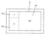
図6は、利用可能になったタッチパネル47のタッチ検出エリア区分を示す。液晶表示パネル46のタッチパネル47の左側を上下方向でほぼ3等分し、上側を上感応域(感応エリア)47aとし、下側を下感応エリア47bとする。上感応エリア47aと下感応エリア47bの間を、タッチ操作に感応しないブランクエリア47d(タッチしても無視されるエリア)とする。ブランクエリア47dは、操作状況に応じて、上感応エリア47a又は下感応エリア47bに合体される。 FIG. 6 shows the touch detection area section of the
タッチパネル47の残りの部分を決定エリア47cとする。決定エリア47cは、上感応エリア47a及び下感応エリア47bのほぼ2倍の横幅を具備する。The remaining part of the
好ましくは、液晶表示パネル46には、上感応エリア47a、下感応エリア47b及び決定エリア47cを視覚的に確認できるような文字又は画像を表示しておく。 Preferably, the liquid
上感応エリア47aは、メニュー表示の上への移動、又は上側の要素の選択に対応し、下感応エリア47bは、メニュー表示の下への移動、又は、上側の要素の選択に対応する。 The upper
例えば、図4に示すように、「メニュー」44aが選択されている状態で、ユーザが下感応エリア47bに1回触れることにより、「逆光補正」44bに変更されると共に、タッチパネル47のタッチ位置情報がシステム制御装置26を介してメモリ30に記憶される。システム制御装置26は、メモリ30に記憶されるタッチパネル47のタッチ位置情報に基づき、ビデオ制御装置38と連動して、図7に示すように、タッチパネルの下感応エリア47bを、ブランクエリア47dを加えた範囲に拡げる。これにより、下感応エリア47bの面積が2倍になる。For example, as shown in FIG. 4, when the “menu” 44 a is selected, the user touches the lower
ユーザが、もう一度、下感応エリア47bに触れると、システム制御装置26は、「逆光補正」44bから「アイリス調整」44cに変更し、同時に、タッチパネル47の位置情報に関するメモリ30の記憶を更新する。この段階で、ユーザがタッチパネル47の決定エリア47cに触れると、システム制御装置26は、EVF44の画面内に、図5に示すようなアイリス調整操作の画面を表示する。When the user touches the lower
このとき、上感応エリア47aは、EVF44の増加マーク44fに対応し、下感応エリア47bは、EVF44の減少マーク44gに対応する。即ち、システム制御装置26は、撮影者が上感応エリア47aをタッチしたときには、絞りを一段開く指示であると理解し、撮影者が下感応エリア47bをタッチしたときには、絞りを一段閉じる指示であると理解する。決定エリア47cの操作に応じて、システム制御装置26は、最終的に、指示された絞り値に絞りを制御する。 At this time, the upper
このように、本実施例では、タッチパネル47の下感応エリア47bの操作に対して、ブランクエリア47dを下感応エリア47bに含めることで下感応エリア47bの面積を倍増する。また、同様に、上感応エリア47aの操作に対して、ブランクエリア47dを上感応エリア47aに含めることで上感応エリア47aの面積を倍増する。 Thus, in this embodiment, the area of the lower
そのため、直前に上感応エリア47aをタッチし、引き続いて上を指示しようとしているにもかかわらず、操作面が見えないためブランクエリア47dをタッチした場合にも、確実に上方向を指示することができる。 Therefore, even if the upper
この様に、本実施例では、直前の操作状況に応じて、タッチパネルの感応域の面積を拡大縮小することにより、ブラインドタッチでも、適切に操作することができる。 As described above, in this embodiment, the area of the sensitive area of the touch panel is enlarged / reduced in accordance with the immediately preceding operation situation, so that an appropriate operation can be performed even with a blind touch.
図8は、今回のタッチ領域と前回のタッチ領域との組み合わせに対する、システム制御装置26の制御動作例を示す。 FIG. 8 shows a control operation example of the
タッチパネル47以外にも、連続する又は離散的な複数の感知点を具備する非接触センサ、例えば、静電式又は熱感知式等の近接センサを使ってもよい。Besides the
タッチパネル47が利用可能なとき、操作装置52からの各種操作(メニューボタン、逆光補正、エフェクトボタン等)を無効としても、有効のままでも、どちらでもよい。 When the
EVF44の画面内でメニューを左右に並べて配置したときのように、左右で選択するときには、タッチパネル47でも、タッチ域の下側に左右に並べて感応エリアを配置し、上下の選択に対して、図9に示したように、タッチ域の左側(又は右側)に上下に並べて感応エリアを配置するようにしてよい。即ち、表示画面上の操作マークの配置に応じて、タッチパネル47の感応域を同様に並べて配置し、前回の操作位置に応じて、何れかの感応域を拡大する。When selecting menus on the left and right, such as when the menus are arranged side by side in the
図8は、EVF44内でメニューを左右に並べて配置した画面例であり、図9は、図8に示すメニュー表示に対するタッチパネル47の感応域の配置を示す。図8に示す例では、「メニュー」144a、「逆光補正」144b、「アイリス調整」144c、「エフェクト」144d及び「戻る」144eが左右に並べて配置されている。 FIG. 8 shows an example of a screen in which menus are arranged side by side in the
図8に示すメニュー表示に対して、液晶表示パネル46のタッチパネル47の下側を左右方向でほぼ3等分し、左側を左感応エリア147eとし、右側を右感応エリア147fとする。左感応エリア147eと右感応エリア147fの間を、タッチ操作に感応しないブランクエリア147h(タッチしても無視されるエリア)とする。ブランクエリア147dは、ブランクエリア47dと同様に、操作状況に応じて、左感応エリア147e又は右感応エリア147fに合体される。 With respect to the menu display shown in FIG. 8, the lower side of the
タッチパネル47の残りの部分を決定エリア147gとする。決定エリア147gは、左感応エリア147e及び右感応エリア147fのほぼ2倍の縦幅を具備する。The remaining part of the
好ましくは、液晶表示パネル146には、左感応エリア147e、右感応エリア147f及び決定エリア147gを視覚的に確認できるような文字又は画像を表示しておく。 Preferably, the liquid crystal display panel 146 displays characters or images that allow the left
左感応エリア147eは、メニュー表示の左への移動、又は左側の要素の選択に対応し、右感応エリア147fは、メニュー表示の右への移動、又は、右側の要素の選択に対応する。 The left
例えば、図8に示すように、「メニュー」144aが選択されている状態で、ユーザが右感応エリア147fに1回触れることにより、「逆光補正」144bに変更されると共に、タッチパネル47のタッチ位置情報がシステム制御装置26を介してメモリ30に記憶される。システム制御装置26は、メモリ30に記憶されるタッチパネル47のタッチ位置情報に基づき、ビデオ制御装置38と連動して、図10に示すように、タッチパネルの右感応エリア147fを、ブランクエリア147hを加えた範囲に拡げる。これにより、右感応エリア147fの面積が2倍になる。For example, as shown in FIG. 8, when the “menu” 144a is selected, the user touches the right sensitive area 147f once to change to the “backlight correction” 144b and the touch position of the
ユーザが、もう一度、右感応エリア147fに触れると、システム制御装置26は、「逆光補正」144bから「アイリス調整」144cに変更し、同時に、タッチパネル47の位置情報に関するメモリ30の記憶を更新する。この段階で、ユーザがタッチパネル47の決定エリア147gに触れると、システム制御装置26は、EVF44の画面内に、図11に示すようなアイリス調整操作の画面を表示する。勿論、図5に示すような操作画面でも良いが、左右の操作と上下の操作が混在する例を説明するために、図11に示す操作画面を示す。When the user touches the right sensitive area 147f again, the
図11に示すような上下の操作画面に対し、システム制御装置26は、タッチパネルの感応域を図12に示すように、図6と同様に配置する。即ち、タッチパネル47の左側を上下方向でほぼ3等分し、上側を上感応エリア147aとし、下側を下感応エリア147bとする。上感応エリア147aと下感応エリア147bの間を、タッチ操作に感応しないブランクエリア147d(タッチしても無視されるエリア)とする。ブランクエリア147dは、操作状況に応じて、上感応エリア147a又は下感応エリア147bに合体される。For the upper and lower operation screens as shown in FIG. 11, the
タッチパネル47の残りの部分を決定エリア147cとする。決定エリア147cは、上感応エリア147a及び下感応エリア147bのほぼ2倍の横幅を具備する。 The remaining part of the
上感応エリア147aは、EVF44の増加マーク144fに対応し、下感応エリア147bは、EVF44の減少マーク144gに対応する。即ち、システム制御装置26は、撮影者が上感応エリア147aをタッチしたときには、絞りを一段開く指示であると理解し、撮影者が下感応エリア147bをタッチしたときには、絞りを一段閉じる指示であると理解する。また、下感応エリア147bの連続した操作に対してブランクエリア147dを下感応エリア147bに含めることで下感応エリア147bの面積を倍増し、同様に、上感応エリア147aの操作に対して、ブランクエリア147dを上感応エリア147aに含めることで上感応エリア147aの面積を倍増する。このように、直前の操作状況に応じて、タッチパネルの感応域の面積を拡大縮小することにより、ブラインドタッチでも、適切に操作することができる。決定エリア147cの操作に応じて、システム制御装置26は、最終的に、指示された絞り値に絞りを制御する。The upper
アイリス調整が終了し、図8に示す操作画面に戻った段階で、システム制御装置26は、タッチパネル47の感応域を図9に示す構成に戻す。 When the iris adjustment is completed and the operation screen shown in FIG. 8 is restored, the
直前に操作した感応エリアを拡大する実施例を説明したが、これらの実施例は、同じ感応エリアを連続して操作する可能性が高いケースに適している。例えば、上エリアタッチ後、ブランクエリアを上エリアに含めることで、前回のタッチ位置から少し下をタッチした場合に、下方向の指示になってしまうことを防止できる。これに対して、異なる感応エリアを選択する可能性が高いケースでは、逆に、非操作の感応エリアを拡大することで、良好な操作性を得ることができる。このケースでは、例えば、上エリアのタッチに対し、ブランクエリアを下エリアに加える。これにより、上方向の指示の後に下方向を指示したい場合に、誤ってブランクエリアをタッチしても、下エリアの指示と認識されるようになり、誤操作の可能性を低減できる。 Although the example which expands the sensitive area operated immediately before was described, these examples are suitable for the case where possibility that the same sensitive area will be operated continuously is high. For example, by including a blank area in the upper area after touching the upper area, it is possible to prevent a downward instruction when touching a little from the previous touch position. On the other hand, in a case where there is a high possibility of selecting a different sensitive area, conversely, it is possible to obtain good operability by expanding the non-operating sensitive area. In this case, for example, a blank area is added to the lower area for an upper area touch. Accordingly, when it is desired to instruct a downward direction after an upward instruction, even if the blank area is touched by mistake, the instruction is recognized as an instruction for the lower area, and the possibility of an erroneous operation can be reduced.
撮像装置に適用した実施例を説明したが、本発明は、モニタ画面を見つつ、タッチパネルを手探り状態で操作するような環境で使用する電子機器一般に適用して、有用な操作性を享受できるものである。例えば、顕微鏡観察下で何かの操作をするケースや、ヘッドマウントディスプレイで内容を観察しながら、手元のタッチパネルでメニュー操作する電子機器等が考えられる。 Although the embodiment applied to the imaging apparatus has been described, the present invention can be applied to general electronic devices used in an environment where the touch panel is operated in a groping state while watching the monitor screen, and can enjoy useful operability. It is. For example, a case where an operation is performed under microscope observation, an electronic device where a menu operation is performed with a touch panel at hand while the contents are observed with a head-mounted display, and the like can be considered.
10 撮像装置
12 撮影レンズ
14 レンズ駆動装置
16 撮像素子
18 タイミングジェネレータ(TG)
20 CDS/AGC回路
22 A/D変換器
24 カメラ信号処理装置
26 システム制御装置
28 メモリ制御装置
30 メモリ
32 記録再生装置
34 記録媒体
36 デジタルデータI/F
38 ビデオ制御装置
38a 検出装置
40 テープ記録再生装置
42 磁気テープ
44 電子ビューファインダ(EVF)
46 液晶表示パネル(LCD)
47 タッチパネル
48 回転ヒンジ
50 ライン入出力端子
52 操作装置
54 計時装置
52a シャッタボタン
52b 動画像撮影スイッチ
52c 停止スイッチ
52d 再生スイッチ
52e 視度調整スライダ
52f ズームスイッチ
52g モードダイヤルDESCRIPTION OF
20 CDS / AGC circuit 22 A /
38 Video control device
46 Liquid crystal display panel (LCD)
47
Claims (10)
Translated fromJapanese互いに重複しない位置に第1のエリアと第2のエリアを有する操作手段と、
前記第1のエリアが操作された場合に前記表示装置に表示された複数の項目のうちの選択されている項目を第1の方向に移動し、前記第2のエリアが操作された場合に前記選択されている項目を第2の方向に移動するように、前記表示装置に指示する表示制御手段と、
前記第1のエリアが操作された場合に前記第1のエリアの面積を拡大する操作制御手段とを備え、
前記操作制御手段は、拡大前の前記第1のエリアを含むように、前記表示装置に表示された複数の項目が並んでいる方向に対応した方向に前記第1のエリアの面積を拡大することを特徴とする操作デバイス。An operation device that selects any one of a plurality of items displayed side by side on a display device,
Operating means havinga first area toa second area in a position that does not overlapeach other physician,
When the first area is operated, the selected item of the plurality of items displayed on the display device is moved in the first direction, and when the second area is operated, Display control means for instructing the display device to move the selected item in the second direction;
Operation control means for enlarging the area of the first area when the first area is operated,
The operation control means enlarges the area of the first area in a direction corresponding to a direction in which a plurality of items displayed on the display device are arranged so as to include the first area before enlargement. Operation device characterized by.
互いに重複しない位置に第1のエリアと第2のエリアを有する操作手段と、
前記第1のエリアが操作された場合に前記表示装置に表示された複数の項目のうちの選択されている項目を第1の方向に移動し、前記第2のエリアが操作された場合に前記選択されている項目を第2の方向に移動するように、前記表示装置に指示する表示制御手段と、
前記第1のエリアが操作された場合に前記第2のエリアの面積を拡大する操作制御手段とを備え、
前記操作制御手段は、拡大前の前記第2のエリアを含むように、前記表示装置に表示された複数の項目が並んでいる方向に対応した方向に前記第2のエリアの面積を拡大することを特徴とする操作デバイス。An operation device that selects any one of a plurality of items displayed side by side on a display device,
Operating means havinga first area toa second area in a position that does not overlapeach other physician,
When the first area is operated, the selected item of the plurality of items displayed on the display device is moved in the first direction, and when the second area is operated, Display control means for instructing the display device to move the selected item in the second direction;
Operation control means for enlarging the area of the second area when the first area is operated,
The operation control means enlarges the area of the second area in a direction corresponding to a direction in which a plurality of items displayed on the display device are arranged so as to include the second area before enlargement. Operation device characterized by.
前記表示制御手段は、前記指示手段による前記選択項目の決定の指示に応じて前記選択項目に関する調整のための調整用画面を表示するように前記表示装置に指示し、The display control means instructs the display device to display an adjustment screen for adjustment related to the selection item according to an instruction to determine the selection item by the instruction means,
前記指示手段は、前記調整用画面が前記表示装置に表示された後で、前記第1のエリアまたは前記第2のエリアが操作された場合に、前記選択項目に関する調整を指示することを特徴とする請求項1または2に記載の操作デバイス。The instructing unit instructs adjustment regarding the selection item when the first area or the second area is operated after the adjustment screen is displayed on the display device. The operating device according to claim 1 or 2.
前記指示手段は、前記第3のエリアが操作された場合に前記選択項目の決定を指示することを特徴とする請求項3に記載の操作デバイス。BeforeSL operating meansincludes a thirdarea ofa position that does not overlap the first area and the secondarea,
It said instructing means, an operation device according to claim3, wherein theinstructing the determined selection item when the third area is operated.
互いに重複しない位置に第1のエリアと第2のエリアを有する操作手段における前記第1のエリアが操作された場合に前記表示装置に表示された複数の項目のうちの選択項目を第1の方向に移動し、前記第2のエリアが操作された場合に前記選択項目を第2の方向に移動するように、前記表示装置に指示し、When the first area in the operation means having the first area and the second area at a position that does not overlap with each other is operated, the selection item among the plurality of items displayed on the display device is changed to the first direction. Instructing the display device to move the selection item in the second direction when the second area is operated,
前記第1のエリアが操作された場合に、拡大前の前記第1のエリアを含むように、前記表示装置に表示された複数の項目が並んでいる方向に対応した方向に前記第1のエリアの面積を拡大することを特徴とする操作方法。When the first area is operated, the first area is in a direction corresponding to a direction in which a plurality of items displayed on the display device are arranged so as to include the first area before enlargement. The operation method characterized by enlarging the area.
互いに重複しない位置に第1のエリアと第2のエリアを有する操作手段における前記第1のエリアが操作された場合に前記表示装置に表示された複数の項目のうちの選択項目を第1の方向に移動し、前記第2のエリアが操作された場合に前記選択項目を第2の方向に移動するように、前記表示装置に指示し、When the first area in the operation means having the first area and the second area at a position that does not overlap with each other is operated, the selection item among the plurality of items displayed on the display device is changed to the first direction. Instructing the display device to move the selection item in the second direction when the second area is operated,
前記第1のエリアが操作された場合に、拡大前の前記第2のエリアを含むように、前記表示装置に表示された複数の項目が並んでいる方向に対応した方向に前記第2のエリアの面積を拡大することを特徴とする操作方法。When the first area is operated, the second area is in a direction corresponding to a direction in which a plurality of items displayed on the display device are arranged so as to include the second area before enlargement. The operation method characterized by enlarging the area.
前記第1のマークの表示位置に対応した位置に第1のエリアが配置され、前記第2のマークの表示位置に対応した位置に第2のエリアが配置され、前記第1のエリアと前記第2のエリアとが互いに重複しない位置に配置された操作手段と、A first area is disposed at a position corresponding to the display position of the first mark, a second area is disposed at a position corresponding to the display position of the second mark, and the first area and the first area Operating means arranged at a position where the two areas do not overlap each other;
前記第1のエリアが操作された場合に前記調整項目に関する増加方向への調整を指示し、前記第2のエリアが操作された場合に前記調整項目に関する減少方向への調整を指示する手段と、Means for instructing adjustment in the increasing direction with respect to the adjustment item when the first area is operated, and instructing adjustment in the decreasing direction with respect to the adjustment item when the second area is operated;
前記第1のエリアが操作された場合に前記第1のエリアの面積を拡大する操作制御手段とを備え、Operation control means for enlarging the area of the first area when the first area is operated,
前記操作制御手段は、拡大前の前記第1のエリアを含むように、前記表示装置に表示された前記第1のマークと前記第2のマークとが並んでいる方向に対応した方向に前記第1のエリアの面積を拡大することを特徴とする操作デバイス。The operation control means includes the first mark in a direction corresponding to a direction in which the first mark and the second mark displayed on the display device are arranged so as to include the first area before enlargement. An operation device that enlarges the area of one area.
前記第1のマークの表示位置に対応した位置に第1のエリアが配置され、前記第2のマークの表示位置に対応した位置に第2のエリアが配置され、前記第1のエリアと前記第2のエリアとが互いに重複しない位置に配置された操作手段と、A first area is disposed at a position corresponding to the display position of the first mark, a second area is disposed at a position corresponding to the display position of the second mark, and the first area and the first area Operating means arranged at a position where the two areas do not overlap each other;
前記第1のエリアが操作された場合に前記調整項目に関する増加方向への調整を指示し、前記第2のエリアが操作された場合に前記調整項目に関する減少方向への調整を指示する手段と、Means for instructing adjustment in the increasing direction with respect to the adjustment item when the first area is operated, and instructing adjustment in the decreasing direction with respect to the adjustment item when the second area is operated;
前記第2のエリアが操作された場合に前記第2のエリアの面積を拡大する操作制御手段とを備え、Operation control means for enlarging the area of the second area when the second area is operated,
前記操作制御手段は、拡大前の前記第2のエリアを含むように、前記表示装置に表示された前記第1のマークと前記第2のマークとが並んでいる方向に対応した方向に前記第2のエリアの面積を拡大することを特徴とする操作デバイス。The operation control means includes the first mark in a direction corresponding to a direction in which the first mark and the second mark displayed on the display device are arranged so as to include the second area before enlargement. 2. An operation device characterized by enlarging the area of the two areas.
前記第1のマークの表示位置に対応した位置に第1のエリアが配置され、前記第2のマークの表示位置に対応した位置に第2のエリアが配置され、前記第1のエリアと前記第2のエリアとが互いに重複しない位置に配置された操作手段における前記第1のエリアが操作された場合に前記調整項目に関する増加方向への調整を指示し、前記第2のエリアが操作された場合に前記調整項目に関する減少方向への調整を指示し、A first area is disposed at a position corresponding to the display position of the first mark, a second area is disposed at a position corresponding to the display position of the second mark, and the first area and the first area When the first area in the operating means arranged at a position where the two areas do not overlap with each other is operated, an adjustment in the increasing direction with respect to the adjustment item is instructed, and the second area is operated Instruct the adjustment to decrease in the adjustment item,
前記第1のエリアが操作された場合に、拡大前の前記第1のエリアを含むように、前記表示装置に表示された前記第1のマークと前記第2のマークとが並んでいる方向に対応した方向に前記第1のエリアの面積を拡大することを特徴とする操作方法。When the first area is operated, the first mark and the second mark displayed on the display device are arranged in a direction so as to include the first area before enlargement. An operation method characterized by enlarging the area of the first area in a corresponding direction.
前記第1のマークの表示位置に対応した位置に第1のエリアが配置され、前記第2のマークの表示位置に対応した位置に第2のエリアが配置され、前記第1のエリアと前記第2のエリアとが互いに重複しない位置に配置された操作手段における前記第1のエリアが操作された場合に前記調整項目に関する増加方向への調整を指示し、前記第2のエリアが操作された場合に前記調整項目に関する減少方向への調整を指示し、A first area is disposed at a position corresponding to the display position of the first mark, a second area is disposed at a position corresponding to the display position of the second mark, and the first area and the first area When the first area in the operating means arranged at a position where the two areas do not overlap with each other is operated, an adjustment in the increasing direction with respect to the adjustment item is instructed, and the second area is operated Instruct the adjustment to decrease in the adjustment item,
前記第2のエリアが操作された場合に、拡大前の前記第2のエリアを含むように、前記表示装置に表示された前記第1のマークと前記第2のマークとが並んでいる方向に対応した方向に前記第2のエリアの面積を拡大することを特徴とする操作方法。When the second area is operated, the first mark and the second mark displayed on the display device are arranged in a direction so as to include the second area before enlargement. An operation method characterized by enlarging the area of the second area in a corresponding direction.
Priority Applications (1)
| Application Number | Priority Date | Filing Date | Title |
|---|---|---|---|
| JP2006334063AJP4857097B2 (en) | 2006-12-12 | 2006-12-12 | Operation device and control method thereof |
Applications Claiming Priority (1)
| Application Number | Priority Date | Filing Date | Title |
|---|---|---|---|
| JP2006334063AJP4857097B2 (en) | 2006-12-12 | 2006-12-12 | Operation device and control method thereof |
Publications (3)
| Publication Number | Publication Date |
|---|---|
| JP2008146429A JP2008146429A (en) | 2008-06-26 |
| JP2008146429A5 JP2008146429A5 (en) | 2010-01-28 |
| JP4857097B2true JP4857097B2 (en) | 2012-01-18 |
Family
ID=39606529
Family Applications (1)
| Application Number | Title | Priority Date | Filing Date |
|---|---|---|---|
| JP2006334063AExpired - Fee RelatedJP4857097B2 (en) | 2006-12-12 | 2006-12-12 | Operation device and control method thereof |
Country Status (1)
| Country | Link |
|---|---|
| JP (1) | JP4857097B2 (en) |
Families Citing this family (8)
| Publication number | Priority date | Publication date | Assignee | Title |
|---|---|---|---|---|
| JP2010092270A (en)* | 2008-10-08 | 2010-04-22 | Nec Corp | Information processing terminal, information processing method, and program |
| US10705692B2 (en)* | 2009-05-21 | 2020-07-07 | Sony Interactive Entertainment Inc. | Continuous and dynamic scene decomposition for user interface |
| JP2011101184A (en)* | 2009-11-05 | 2011-05-19 | Sony Corp | Photographing device, and method and program for controlling photographing |
| JP6112819B2 (en)* | 2012-10-10 | 2017-04-12 | オリンパス株式会社 | Electronic device, driving method and program |
| US9760270B2 (en) | 2013-04-16 | 2017-09-12 | Honda Motor Co., Ltd. | Vehicular electronic device |
| JP5881657B2 (en)* | 2013-09-26 | 2016-03-09 | オリンパス株式会社 | Display device, imaging system, display method, and display program |
| JP5830564B2 (en)* | 2014-04-09 | 2015-12-09 | オリンパス株式会社 | Imaging apparatus and mode switching method in imaging apparatus |
| JP6017656B2 (en)* | 2015-10-22 | 2016-11-02 | オリンパス株式会社 | Imaging apparatus and mode switching method in imaging apparatus |
Family Cites Families (5)
| Publication number | Priority date | Publication date | Assignee | Title |
|---|---|---|---|---|
| JPH0436638A (en)* | 1990-06-01 | 1992-02-06 | Hitachi Ltd | Crevice corrosion monitoring method and equipment |
| JP4178484B2 (en)* | 1998-04-06 | 2008-11-12 | 富士フイルム株式会社 | Camera with monitor |
| JP4551507B2 (en)* | 1998-08-17 | 2010-09-29 | ソニー株式会社 | Input operation device and input operation method |
| JP2000155760A (en)* | 1998-11-19 | 2000-06-06 | Koonet:Kk | Portable collection and delivery operation assisting device, delivery information data distribution system, and recording medium |
| JP2005234958A (en)* | 2004-02-20 | 2005-09-02 | Nissan Motor Co Ltd | Touch panel device |
- 2006
- 2006-12-12JPJP2006334063Apatent/JP4857097B2/ennot_activeExpired - Fee Related
Also Published As
| Publication number | Publication date |
|---|---|
| JP2008146429A (en) | 2008-06-26 |
Similar Documents
| Publication | Publication Date | Title |
|---|---|---|
| JP4857097B2 (en) | Operation device and control method thereof | |
| JP5613005B2 (en) | camera | |
| JP6765956B2 (en) | Imaging control device and its control method | |
| KR101860571B1 (en) | Image processing apparatus, image capturing apparatus, image processing method, and non-transitory computer storage device | |
| JP4510713B2 (en) | Digital camera | |
| JP4655135B2 (en) | Imaging apparatus, imaging area display method, and imaging area display program | |
| JP6833506B2 (en) | Imaging device and its control method | |
| JP6833505B2 (en) | Imaging control device and its control method | |
| US20050204311A1 (en) | Photographing apparatus for displaying OSD menu and method thereof | |
| JP5995637B2 (en) | IMAGING DEVICE, IMAGING DEVICE CONTROL METHOD, PROGRAM, AND STORAGE MEDIUM | |
| JP2009077228A (en) | Imaging apparatus and control method thereof | |
| CN1777226B (en) | Apparatus and method for rotating image in digital camera | |
| JP2013021548A (en) | Image pickup device, image reproduction device, and program | |
| JP2009077226A (en) | Imaging apparatus, control method therefor, program, and storage medium storing program | |
| JP5506589B2 (en) | Imaging apparatus, control method therefor, program, and recording medium | |
| JP2016103666A (en) | Electronic apparatus and imaging device | |
| JP2003233368A (en) | Image display control device and method | |
| JP4504158B2 (en) | Camera, tracking device, tracking method, and tracking program | |
| JP5058133B2 (en) | Camera, camera display method and image display program | |
| JP5117356B2 (en) | Camera, camera display method and image display program | |
| JP2007028229A (en) | Photographing device | |
| JP2014225846A (en) | Imaging apparatus, control method and program thereof | |
| JP5930693B2 (en) | Movie recording apparatus and control method thereof | |
| JP5355347B2 (en) | Information processing apparatus and information processing apparatus control method | |
| JP2007336522A (en) | Imaging apparatus |
Legal Events
| Date | Code | Title | Description |
|---|---|---|---|
| A521 | Request for written amendment filed | Free format text:JAPANESE INTERMEDIATE CODE: A523 Effective date:20091204 | |
| A621 | Written request for application examination | Free format text:JAPANESE INTERMEDIATE CODE: A621 Effective date:20091204 | |
| A977 | Report on retrieval | Free format text:JAPANESE INTERMEDIATE CODE: A971007 Effective date:20110524 | |
| A131 | Notification of reasons for refusal | Free format text:JAPANESE INTERMEDIATE CODE: A131 Effective date:20110607 | |
| A521 | Request for written amendment filed | Free format text:JAPANESE INTERMEDIATE CODE: A523 Effective date:20110728 | |
| TRDD | Decision of grant or rejection written | ||
| A01 | Written decision to grant a patent or to grant a registration (utility model) | Free format text:JAPANESE INTERMEDIATE CODE: A01 Effective date:20111025 | |
| A01 | Written decision to grant a patent or to grant a registration (utility model) | Free format text:JAPANESE INTERMEDIATE CODE: A01 | |
| A61 | First payment of annual fees (during grant procedure) | Free format text:JAPANESE INTERMEDIATE CODE: A61 Effective date:20111031 | |
| FPAY | Renewal fee payment (event date is renewal date of database) | Free format text:PAYMENT UNTIL: 20141104 Year of fee payment:3 | |
| R151 | Written notification of patent or utility model registration | Ref document number:4857097 Country of ref document:JP Free format text:JAPANESE INTERMEDIATE CODE: R151 | |
| FPAY | Renewal fee payment (event date is renewal date of database) | Free format text:PAYMENT UNTIL: 20141104 Year of fee payment:3 | |
| RD03 | Notification of appointment of power of attorney | Free format text:JAPANESE INTERMEDIATE CODE: R3D03 | |
| LAPS | Cancellation because of no payment of annual fees |