JP4856260B2 - Electronics - Google Patents
ElectronicsDownload PDFInfo
- Publication number
- JP4856260B2 JP4856260B2JP2010111024AJP2010111024AJP4856260B2JP 4856260 B2JP4856260 B2JP 4856260B2JP 2010111024 AJP2010111024 AJP 2010111024AJP 2010111024 AJP2010111024 AJP 2010111024AJP 4856260 B2JP4856260 B2JP 4856260B2
- Authority
- JP
- Japan
- Prior art keywords
- support member
- housing
- wall
- antenna
- electronic device
- Prior art date
- Legal status (The legal status is an assumption and is not a legal conclusion. Google has not performed a legal analysis and makes no representation as to the accuracy of the status listed.)
- Expired - Fee Related
Links
Images


Classifications
- G—PHYSICS
- G06—COMPUTING OR CALCULATING; COUNTING
- G06F—ELECTRIC DIGITAL DATA PROCESSING
- G06F1/00—Details not covered by groups G06F3/00 - G06F13/00 and G06F21/00
- G06F1/16—Constructional details or arrangements
- G06F1/1613—Constructional details or arrangements for portable computers
- G06F1/1633—Constructional details or arrangements of portable computers not specific to the type of enclosures covered by groups G06F1/1615 - G06F1/1626
- G06F1/1656—Details related to functional adaptations of the enclosure, e.g. to provide protection against EMI, shock, water, or to host detachable peripherals like a mouse or removable expansions units like PCMCIA cards, or to provide access to internal components for maintenance or to removable storage supports like CDs or DVDs, or to mechanically mount accessories
- G—PHYSICS
- G06—COMPUTING OR CALCULATING; COUNTING
- G06F—ELECTRIC DIGITAL DATA PROCESSING
- G06F1/00—Details not covered by groups G06F3/00 - G06F13/00 and G06F21/00
- G06F1/16—Constructional details or arrangements
- G06F1/1613—Constructional details or arrangements for portable computers
- G06F1/1615—Constructional details or arrangements for portable computers with several enclosures having relative motions, each enclosure supporting at least one I/O or computing function
- G06F1/1616—Constructional details or arrangements for portable computers with several enclosures having relative motions, each enclosure supporting at least one I/O or computing function with folding flat displays, e.g. laptop computers or notebooks having a clamshell configuration, with body parts pivoting to an open position around an axis parallel to the plane they define in closed position
- H—ELECTRICITY
- H01—ELECTRIC ELEMENTS
- H01Q—ANTENNAS, i.e. RADIO AERIALS
- H01Q1/00—Details of, or arrangements associated with, antennas
- H01Q1/12—Supports; Mounting means
- H01Q1/22—Supports; Mounting means by structural association with other equipment or articles
- H01Q1/2258—Supports; Mounting means by structural association with other equipment or articles used with computer equipment
- H01Q1/2266—Supports; Mounting means by structural association with other equipment or articles used with computer equipment disposed inside the computer
- H—ELECTRICITY
- H01—ELECTRIC ELEMENTS
- H01Q—ANTENNAS, i.e. RADIO AERIALS
- H01Q1/00—Details of, or arrangements associated with, antennas
- H01Q1/36—Structural form of radiating elements, e.g. cone, spiral, umbrella; Particular materials used therewith
- H01Q1/38—Structural form of radiating elements, e.g. cone, spiral, umbrella; Particular materials used therewith formed by a conductive layer on an insulating support
Landscapes
- Engineering & Computer Science (AREA)
- Computer Hardware Design (AREA)
- General Engineering & Computer Science (AREA)
- Theoretical Computer Science (AREA)
- Physics & Mathematics (AREA)
- Human Computer Interaction (AREA)
- General Physics & Mathematics (AREA)
- Mathematical Physics (AREA)
- Support Of Aerials (AREA)
- Variable-Direction Aerials And Aerial Arrays (AREA)
Description
Translated fromJapanese本発明の実施形態は、電子機器に関する。 Embodiments described herein relate generally to an electronic apparatus.
従来、ディスプレイパネルが前面側に露出する状態で収容された筐体の後壁にアンテナが取り付けられた電子機器が知られている。 2. Description of the Related Art Conventionally, there is known an electronic device in which an antenna is attached to a rear wall of a housing that is accommodated with a display panel exposed to the front side.
この種の電子機器では、筐体の後壁にアンテナが取り付けられることで、筐体が組み立てにくくなったり分解しにくくなったりする等の不都合が生じる場合があった。 In this type of electronic device, there are cases in which the antenna is attached to the rear wall of the housing, which causes problems such as difficulty in assembling or disassembling the housing.
そこで、本発明の実施形態は、ディスプレイパネルが収容された筐体内にアンテナが装備されることによって不都合が生じるのをより抑制することが可能な電子機器を得ることを目的の一つとする。 Therefore, an embodiment of the present invention has an object to obtain an electronic device that can further suppress the occurrence of inconvenience caused by mounting an antenna in a housing in which a display panel is accommodated.
本発明の実施形態にかかる電子機器は、筐体と、支持部材と、突起部と、アンテナと、を備える。筐体は、壁を含む。筐体には、電子部品が収容される。支持部材は、電子部品と離間された位置で、筐体の壁に沿って該壁に固定される。突起部は、支持部材の長手方向に沿って該支持部材に設けられる。アンテナは、支持部材に固定される。An electronic device according to an embodiment of the present inventionincludes a housing, a support member, a protrusion, and an antenna. The housing includes a wall. An electronic component is accommodated in the housing. The support member is fixed to the wall along the wall of the housing at a position separated from the electronic component. The protrusion is provided on the support member along the longitudinal direction of the support member. The antenna is fixed to the support member .
以下、図面を参照して、本発明の実施形態について詳細に説明する。なお、以下では、便宜上、第二の本体部の幅方向(左右方向)をX方向、第二の本体部の先端方向をY方向、第二の本体部の厚さ方向をZ方向とする。X軸、Y軸、およびZ軸は、相互に直交する。 Hereinafter, embodiments of the present invention will be described in detail with reference to the drawings. In the following, for the sake of convenience, the width direction (left-right direction) of the second body portion is defined as the X direction, the tip direction of the second body portion is defined as the Y direction, and the thickness direction of the second body portion is defined as the Z direction. The X axis, the Y axis, and the Z axis are orthogonal to each other.
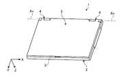
図1,2に示すように、本実施形態にかかる電子機器1は、所謂ノート型のパーソナルコンピュータとして構成されており、矩形状の扁平な第一の本体部2と、矩形状の扁平な第二の本体部3と、を備えている。これら第一の本体部2および第二の本体部3は、ヒンジ機構4を介して、回動軸Ax回りに図1に示す展開状態と図2に示す折り畳み状態との間で相対回動可能に、接続されている。 As shown in FIGS. 1 and 2, the electronic apparatus 1 according to the present embodiment is configured as a so-called notebook personal computer, and includes a rectangular flat first
第一の本体部2には、筐体2aの外面としての前面2b側に露出する状態で、入力操作部としてのキーボード5や、ポインティングデバイス6、クリックボタン7等が設けられている。一方、第二の本体部3には、筐体3aの外面としての前面3b側に露出する状態で、表示装置(電子部品)としてのディスプレイパネル8が設けられている。ディスプレイパネル8は、例えば、LCD(Liquid Crystal Display)として構成される。そして、電子機器1の展開状態では、キーボード5や、ポインティングデバイス6、クリックボタン7、ディスプレイパネル8等が露出して、ユーザが使用可能な状態となる。一方、折り畳み状態では、前面2b,3b同士が相互に近接した状態で対向して、キーボード5や、ポインティングデバイス6、クリックボタン7、ディスプレイパネル8等が、筐体2a,3aによって隠された状態となる。なお、図1では、キーボード5のキー5aは一部のみ図示されている。 The first
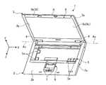
図1,2に示すように、第二の本体部3は、Z方向からの平面視ではX方向に長くY方向に短い長方形状を呈しているとともに、Z方向には薄い扁平な形状に構成されている。第二の本体部3の筐体3aは、図3に示すように、後面3cを形成する底壁3dと当該底壁3dの周縁部で突出する側壁3e1とを有する第一の分割体3Cと、前面3bを形成する天壁3fと当該天壁3fの周縁部で突出する側壁3e2とを有する第二の分割体3Mと、を備えている。第二の分割体3Mの天壁3fの中央部には、矩形状の開口部3gが形成されており、この開口部3gからディスプレイパネル8の表示画面8aが露出している。また、第一の分割体3Cおよび第二の分割体3Mの側壁3e1,3e2は相互に重なり合い、これら側壁3e,3e2によって筐体3aの側壁(周壁部)3eが形成されている。すなわち、第二の本体部3の外郭は、底壁3dや、側壁3e、天壁3f等によって構成されている。なお、筐体3aは、金属材料や合成樹脂材料等で構成することができる。 As shown in FIGS. 1 and 2, the second
そして、図3に示すように、第二の本体部3では、第一の分割体3Cと第二の分割体3Mとによって形成される外郭の内部に、ディスプレイパネル8と、アンテナユニット9とが収容されている。 And in the 2nd main-
ディスプレイパネル8は、Z方向から見た平面視では矩形状であり、かつ厚さ(Z方向の高さ)の比較的薄い扁平な外観を呈している。ディスプレイパネル8は、筐体3aのほぼ中央部に位置するように配置され、例えばディスプレイパネル8の四隅に設けられるブラケット部8bをねじ12等の固定具を用いて固定することによって、第一の分割体3Cに取り付けられる。なお、図3では、ディスプレイパネル8の本体部8cとブラケット部8bとが分けて示されているが、ディスプレイパネル8は、実際には、本体部8cにブラケット部8bを取り付けた状態で、第一の分割体3Cに取り付けられる。また、ブラケット部8bの一端部はヒンジ機構4に接続されている。 The
また、図3に示すように、ディスプレイパネル8の帯状かつ平面状の部品側面8dと筐体3aの側壁3eとの間、すなわち、筐体3a内のディスプレイパネル8(本体部8cまたはブラケット部8b)の部品側面8dの周囲には、細長い矩形枠状のケーブル配策領域Asが形成されている。このケーブル配策領域Asには、ケーブル(図示せず)が配策される。ケーブルは、場所によっては複数本(例えば3本)並行して配策される。ケーブルは、例えば、アンテナ11に接続されるアンテナケーブルや、カメラ(図示せず)に接続されるカメラケーブルである。 Further, as shown in FIG. 3, the display panel 8 (
また、図3に示すように、本実施形態では、第二の分割体3Mの天壁3f上に、側壁3e2(3e)と平行に間隔をあけて対向する突起部3hが設けられている。突起部3hは、ディスプレイパネル8の部品側面8dと筐体3aの側壁3eとの間に、これら部品側面8dおよび側壁3eと平行な姿勢で配置されている。また、突起部3hは、部品側面8dに沿って間欠的に複数箇所に配置されている。ケーブルは、列状に配置される複数の突起部3hと側壁3eとの間に配策される。すなわち、本実施形態では、突起部3hの列と側壁3eとによって、ケーブル配策領域Asが規定されている。また、突起部3hは、ディスプレイパネル8の部品側面8dに対向して設けられている。そして、ディスプレイパネル8が、慣性力の作用等で、筐体3a内で表示画面8aに沿う面内方向(すなわちXY平面に沿う方向)に相対移動して、突起部3hに当接した場合に、突起部3hは、そのディスプレイパネル8の当接によって傾倒して変形し、衝突エネルギを吸収する。すなわち、本実施形態では、突起部3hは、エネルギ吸収部としても機能し、ディスプレイパネル8の保護性を高めている。 As shown in FIG. 3, in the present embodiment, a
アンテナユニット9は、アンテナ支持部材10と、複数のアンテナ11(11A,11B)とを含んでいる。アンテナ11は、比較的小型で薄い基板やフィルム上に、素子や、電子部品、導体経路等(いずれも図示せず)を設けたものとして構成され、例えば、3G(3rd Generation,IMT-2000規格)用のアンテナや、無線LAN(Wireless Local Area Network)用のアンテナとして構成される。また、アンテナ11Aについては、折曲線11aで折り曲げて傾斜可能に構成されている。アンテナ11は、ケーブル配策領域Asで配策されるケーブル(図示せず)を介して、第一の本体部2内に収容された基板(図示せず)に実装された通信回路に接続されている。なお、各アンテナ11の先端側(Y方向先方側)の部分が主として通信機能を担う部分である。 The antenna unit 9 includes an
アンテナ支持部材10は、本実施形態では、第二の本体部3の筐体3aの先端側(Y方向先方側)の端縁3iに沿って略一定幅で延伸する帯板状に、形成されている。また、アンテナ支持部材10の、少なくともアンテナ11が取り付けられる部分(例えば後面10aの全体)は、導体であり、この導体の部分が、アンテナ11のグラウンドとして機能する。よって、アンテナ支持部材10は、例えば、帯板状の金属導体や、後面10a上に導体層(例えば、導体箔、導体膜、導体板等)が設けられた帯板状の絶縁体(例えば合成樹脂等)等として、構成することができる。そして、アンテナ支持部材10の導体部分を、第二の本体部3のグラウンドに電気的に接続するとともに、複数のアンテナ11のグラウンド電極(図示せず)に接続することで、第二の本体部3とアンテナ11との間でグラウンド電位が共通になり、ノイズの混入等の通信の不良を抑制することができる。 In the present embodiment, the
そして、アンテナ支持部材10は、図4〜6にも示すように、筐体3aの底壁3dとディスプレイパネル8の外面としての後面8eとの間に配置された帯板状のベース部10bと、ベース部10bに対して先端側(Y方向先方側)に配置された帯板状の傾斜部10cと、筐体3aの固定部3jに固定されるブラケット部10dと、を有している。図6に示すように、本実施形態では、アンテナ支持部材10の断面は、ベース部10bと傾斜部10cとで屈曲した形状となっており、屈曲しない直線的な形状である場合に比べて、アンテナ支持部材10の剛性が高い。また、ブラケット部10dは、ベース部10bの長手方向両端側(第二の本体部3の幅方向両側、X方向両側)かつ先端側(Y方向先方側)に、矩形状の領域として設けられている。ブラケット部10dには、取付用のねじ12が貫通する貫通部としての貫通孔10eが設けられている。 As shown in FIGS. 4 to 6, the
ベース部10bは、図6に示すように、底壁3dならびにディスプレイパネル8の後面8eと平行な姿勢で、それら底壁3dならびにディスプレイパネル8の双方と間隔をあけて配置されている。これにより、アンテナ支持部材10に取り付けられるアンテナ11も、底壁3dならびにディスプレイパネル8の双方から離間することになり、アンテナ11と底壁3dあるいはディスプレイパネル8とが近くに配置されることでアンテナ11の通信特性に影響が及ぶのを抑制することができる。また、仮に、アンテナ支持部材10がディスプレイパネル8の後面8eに当接した場合、第二の本体部3の組み立て作業時等に、アンテナ支持部材10から押されて、ディスプレイパネル8に何らかの悪影響が及ぶ可能性もある。この点、本実施形態では、アンテナ支持部材10のベース部10bおよび傾斜部10cの双方が、ディスプレイパネル8から離間しているため、ディスプレイパネル8がアンテナ支持部材10に押されるのを抑制することができる。 As shown in FIG. 6, the
傾斜部10cは、図3,4に示すように、アンテナ支持部材10の長手方向両側に形成された一対の切り込み10fでベース部10b(ブラケット部10d)側と分離され、図6にも示すように、切り込み10fの奥側の端部間を結ぶ折曲線10gで前方側(Z方向先方側)へ折り曲げられて、形成されている。すなわち、傾斜部10cは、図6に示すように、ベース部10bの先端側の端縁10hから先端側(Y方向先方側)へ向かうにつれて前方側へ向かっている。よって、アンテナ11Aは、図6に示すように、アンテナ支持部材10の折り曲げに沿って屈曲し、アンテナ11Aの先端部11bは、第二の本体部3の先端側で筐体3aの外郭としての底壁3d、側壁3e、および天壁3fで囲まれた空間Sの中央部に寄せて配置される。これにより、アンテナ11の先端部11bと筐体3aの外郭とが近くに配置されることでアンテナ11の通信特性に影響が及ぶのを、抑制することができる。なお、傾斜部10cのスペック(大きさ、角度等)は、アンテナ11の特性が適切となるように設定される。 As shown in FIGS. 3 and 4, the
ブラケット部10dは、図5に示すように、第一の分割体3Cに設けられた固定部3jとしてのボス部3kと第二の分割体3Mに設けられた固定部3jとしてのボス部3mとの間に、ディスプレイパネル8のブラケット部8bとともに挟持され、ねじ12によって筐体3aに取り付けられている。本実施形態では、第一の分割体3Cのボス部3kに雌ねじ部が設けられ、第二の分割体3Mに形成された貫通孔3nおよびブラケット部8b,10dに形成された貫通孔8f,10eを貫通したねじ12を、第二の分割体3M側から締め付けることで、第一の分割体3C、第二の分割体3M、ディスプレイパネル8、およびアンテナユニット9が、結合されている。なお、ねじ12のヘッド部12aは、貫通孔3nの開口端部に圧入されたプラグ13によって覆われて隠されている。 As shown in FIG. 5, the
アンテナ11は、アンテナ支持部材10に、接着剤や接着テープ等を用いて取り付けられている。上述したように、アンテナ11のグラウンド電極(図示せず)は、アンテナ支持部材10の導体部に電気的に接続される。よって、アンテナ11のアンテナ支持部材10への取り付けに際しては、導電性の接着剤や接着テープ等を用いるのが好適である。アンテナ11は、筐体3aに取り付けられたアンテナ支持部材10に取り付けてもよいし、アンテナ11をアンテナ支持部材10に取り付けたアンテナユニット9を筐体3aに取り付けてもよい。 The
以上の本実施形態では、電子機器1が、電子部品としてのディスプレイパネル8が収容された筐体3aと、筐体3aに固定された支持部材としてのアンテナ支持部材10と、アンテナ支持部材10に固定されたアンテナ11と、を備えている。よって、アンテナ11が筐体3aに直接固定された場合に比べて、アンテナ11の取り付けおよび取り外しをより容易に行うことができる。さらに、本実施形態では、一つのアンテナ支持部材10に複数のアンテナ11が取り付けられたため、アンテナ11の取り付けおよび取り外しをより一層容易に行うことができる。 In the present embodiment described above, the electronic apparatus 1 includes the
また、本実施形態では、アンテナ支持部材10が、ディスプレイパネル8の本体部8cの外面としての後面8eと間隔をあけて配置された。よって、ディスプレイパネル8が近接して配置されることによってアンテナ11の通信特性に影響が及ぶのを抑制することができる。 Further, in the present embodiment, the
また、本実施形態では、アンテナ支持部材10が、筐体3aの外郭(底壁3d、側壁3e、天壁3f等)に沿って配置され、当該外郭に固定された。よって、アンテナ支持部材10により外郭を補強し、筐体3aの剛性を高めることができる。 Further, in the present embodiment, the
また、本実施形態では、アンテナ支持部材10が、外郭としての一つの側壁3eの長手方向両端部間に亘って配置された。よって、アンテナ支持部材10により側壁3eを全体的に補強し、筐体3aの剛性をより一層高めることができる。 Moreover, in this embodiment, the
また、本実施形態では、アンテナ支持部材10が、屈曲した断面を有した。よって、アンテナ支持部材10の剛性を高めて、筐体3aの剛性をより一層高めることができる。 In the present embodiment, the
また、本実施形態では、筐体3aは、相互に間隔をあけて対向する天壁3fおよび底壁3dと、天壁3fおよび底壁3dを接続する側壁3eと、有し、アンテナ支持部材10は、天壁3fおよび底壁3dのうち一方としての底壁3dの近くに配置されるベース部10bと、ベース部10bに接続され側壁3eに近づくにつれて一方から遠ざかる方向へ伸びる傾斜部10cと、を有した。よって、アンテナ11を傾斜部10cに沿って、底壁3d、側壁3e、および天壁3fで囲まれた空間の中央部へ近づけて配置することができて、アンテナ11の通信特性に、底壁3d、側壁3e、および天壁3fの影響が及ぶのを抑制することができる。 In the present embodiment, the
また、本実施形態では、筐体3aが複数の分割体3M,3Cを有し、アンテナ支持部材10が、それら複数の分割体3M,3Cを固定する固定具としてのねじ12によって筐体3aに固定された。よって、分割体3M,3C同士を結合するねじとアンテナ支持部材10を筐体3aに固定するねじとを別個に設けた場合に比べて、部品点数を減らすことができる。また、組み立ての工程数を減らすこともできる。 Further, in the present embodiment, the
また、本実施形態では、電子部品が表示装置としてのディスプレイパネル8であり、筐体3aが、ディスプレイパネル8の後側を覆う第一の分割体3Cと、ディスプレイパネル8の表示画面8aを露出させた状態で当該ディスプレイパネル8の前側を覆う第二の分割体3Mと、を有し、アンテナ11のハーネス(図示せず)が第二の分割体3Mに固定された。よって、ディスプレイパネル8の後側を覆う第一の分割体3Cを比較的容易に着脱することができる。このような構成は、例えば、一旦組み立てられた電子機器1から第一の分割体3Cを取り外して、後面3cに、模様や、文字、画像等を印刷したり、シールやフィルム等を貼り付けたりする(加飾する)場合に、筐体3aから第一の分割体3Cを取り外しやすくなる。また、印刷のため第一の分割体3Cを印刷機等にセットする際に、第一の分割体3Cにアンテナ11やハーネスが付随して処理や作業に支障を来すという不都合を回避することができる。 In the present embodiment, the electronic component is the
また、本実施形態では、電子機器1の組み立てにあたり、作業者は、複数のアンテナ11をアンテナ支持部材10に一体化したアンテナユニット9を筐体3aに取り付けることができる。こうすることで、複数のアンテナ11の取り付けや取り外しをまとめて行うことができるので、取り付けや取り外しの手間を減らしやすくなる。 In the present embodiment, when assembling the electronic apparatus 1, an operator can attach the antenna unit 9 in which the plurality of
また、図7に示す変形例では、アンテナ支持部材10Aが、その長手方向(すなわちX方向)の両端部としてのブラケット部10dと傾斜部10cとを当該アンテナ支持部材10Aの長手方向に接続する屈曲部10iを有した。よって、アンテナ支持部材10Aの剛性をより一層高めることができて、アンテナ支持部材10Aによる筐体3aの補強効果をより一層高めることができる。 Further, in the modification shown in FIG. 7, the
また、図8に示す変形例では、アンテナ支持部材10Bが、その長手方向に沿って伸びる突起部10jを有した。突起部10jは、一例として、ベース部10bの幅方向中央部を前方側に一定幅で細長く凹ませて形成されている。突起部10jにより、アンテナ支持部材10Bの剛性をより一層高めることができ、アンテナ支持部材10Bによる筐体3aの補強効果をより一層高めることができる。なお、突起部は、アンテナ11の性能等に支障を来さない範囲で後方に突出させてもよい。また、突起部は、部分的に形成したり、間欠的に形成したり、複数形成したり、段差状に形成したりしてもよい。 In the modification shown in FIG. 8, the
また、図9に示す変形例では、アンテナ支持部材10Cに、表裏方向(前後方向)に貫通する貫通部としての貫通孔10kを設けた。これにより、アンテナ支持部材10Cをより軽量に構成することができる。貫通部は、切欠等として設けてもよいし、傾斜部10cに設けてもよい。また、貫通部によって、他の部品等との干渉を避けてもよい。 Further, in the modification shown in FIG. 9, the antenna support member 10C is provided with a through
以上、本発明の好適な実施形態について説明したが、本発明は上記実施形態には限定されず、種々の変形が可能である。例えば、本発明は、ノート型のパーソナルコンピュータ以外の電子機器としても実施することができる。また、筐体、支持部材、アンテナ、外郭、断面、突起部、ベース部、傾斜部、固定具、表示装置、第一の分割体、第二の分割体等のスペック(構造や、形状、大きさ、重量、数、材質、配置、位置等)は、適宜に変更して実施することができる。 The preferred embodiments of the present invention have been described above. However, the present invention is not limited to the above embodiments, and various modifications can be made. For example, the present invention can be implemented as an electronic device other than a notebook personal computer. In addition, the specifications (structure, shape, size, etc.) of the housing, support member, antenna, outline, cross section, protrusion, base, inclined part, fixture, display device, first divided body, second divided body, etc. The weight, number, material, arrangement, position, etc.) can be changed as appropriate.
上記実施形態によれば、ディスプレイパネルが収容された筐体内にアンテナが装備されることによって不都合が生じるのをより抑制することができる。 According to the above embodiment, it is possible to further suppress the occurrence of inconvenience due to the antenna being installed in the housing in which the display panel is accommodated.
1…電子機器、3C…第一の分割体、3M…第二の分割体、3a…筐体、3d…底壁(外郭)、3e,3e1,3e2…側壁(外郭)、3f…天壁(外郭)、8…ディスプレイパネル(電子部品、表示装置)、8a…表示画面、8c…本体部、8e…後面(外面)、10…アンテナ支持部材(支持部材)、10b…ベース部、10c…傾斜部、10d…ブラケット部(長手方向両端部)、10i…屈曲部、10j…突起部、12…ねじ(固定具)。 DESCRIPTION OF SYMBOLS 1 ... Electronic device, 3C ... 1st division body, 3M ... 2nd division body, 3a ... Case, 3d ... Bottom wall (outer wall), 3e, 3e1, 3e2 ... Side wall (outer wall), 3f ... Top wall ( Outer), 8 ... Display panel (electronic component, display device), 8a ... Display screen, 8c ... Main body, 8e ... Rear surface (outer surface), 10 ... Antenna support member (support member), 10b ... Base part, 10c ... Inclined Part, 10d ... bracket part (both ends in the longitudinal direction), 10i ... bent part, 10j ... projecting part, 12 ... screw (fixing tool).
Claims (11)
Translated fromJapanese前記電子部品と離間された位置で、前記筐体の壁に沿って該壁に固定された支持部材と、
前記支持部材の長手方向に沿って該支持部材に設けられた突起部と、
前記支持部材に固定されたアンテナと、
を備えた電子機器。A housingthat includes walls and contains electronic components;
A support member fixed tothe wall along the wall of the housingat a position separated from the electronic component ;
A protrusion provided on the support member along the longitudinal direction of the support member;
An antenna fixed to the support member;
Child equipmentpower witha.
前記支持部材は、前記天壁および前記底壁のうち一方の近くに配置されるベース部と、前記ベース部に接続され前記側壁に近づくにつれて前記一方から遠ざかる方向へ伸びる傾斜部と、を有した請求項1〜4のうちいずれか一つに記載の電子機器。The housing has a top wall and a bottom wall facing each otheras the wall with a space therebetween, and a side wall connecting the top wall and the bottom wall,
The support member includes a base portion disposed near one of the top wall and the bottom wall, and an inclined portion that is connected to the base portion and extends in a direction away from the one as the side wall is approached. the electronic device according to any one of請 Motomeko1-4was.
前記支持部材が、前記複数の分割体を固定する固定具によって前記筐体に固定された請求項1〜6のうちいずれか一つに記載の電子機器。The housing has a plurality of divided bodies;
It said support member is an electronic device according to any one of the請 Motomeko1-6fixed to the housing by a retainer that holds the plurality of divided bodies.
前記筐体が、前記表示装置の後側を覆う第一の分割体と、前記表示装置の表示画面を露出させた状態で当該表示装置の前側を覆う第二の分割体と、を有し、
前記アンテナのハーネスが前記第二の分割体に固定された請求項1〜7のうちいずれか一つに記載の電子機器。The electronic component is a display device;
The housing has a first divided body that covers the rear side of the display device, and a second divided body that covers the front side of the display device with the display screen of the display device exposed.
The electronic device according to any one of請 Motomeko1-7 harness of the antenna isfixed to the second split body.
前記第一の筐体とヒンジ部を介して回動可能に接続され、前記ヒンジ部から離間した二つの角部と、該二つの角部間に亘る壁部と、を有した第二の筐体と、A second housing having two corners that are pivotally connected to the first housing via a hinge part and spaced from the hinge part, and a wall part between the two corners. Body,
少なくとも一部が露出した状態で前記第二の筐体に収容された表示装置と、A display device housed in the second housing with at least a portion exposed;
前記第二の筐体内で前記二つの角部に両端支持され、前記二つの角部間で前記壁部および前記表示装置から離間した位置で前記壁部および前記表示装置に沿って延び、アンテナを支持した支持部材と、Both ends are supported by the two corners in the second casing, and extend along the wall and the display device at a position spaced from the wall and the display device between the two corners, A supported support member;
を備えた、電子機器。With electronic equipment.
Priority Applications (3)
| Application Number | Priority Date | Filing Date | Title |
|---|---|---|---|
| JP2010111024AJP4856260B2 (en) | 2010-05-13 | 2010-05-13 | Electronics |
| US13/045,378US20110279948A1 (en) | 2010-05-13 | 2011-03-10 | Electronic Device |
| US13/584,305US20120307475A1 (en) | 2010-05-13 | 2012-08-13 | Electronic Device |
Applications Claiming Priority (1)
| Application Number | Priority Date | Filing Date | Title |
|---|---|---|---|
| JP2010111024AJP4856260B2 (en) | 2010-05-13 | 2010-05-13 | Electronics |
Publications (2)
| Publication Number | Publication Date |
|---|---|
| JP2011239327A JP2011239327A (en) | 2011-11-24 |
| JP4856260B2true JP4856260B2 (en) | 2012-01-18 |
Family
ID=44911593
Family Applications (1)
| Application Number | Title | Priority Date | Filing Date |
|---|---|---|---|
| JP2010111024AExpired - Fee RelatedJP4856260B2 (en) | 2010-05-13 | 2010-05-13 | Electronics |
Country Status (2)
| Country | Link |
|---|---|
| US (2) | US20110279948A1 (en) |
| JP (1) | JP4856260B2 (en) |
Families Citing this family (7)
| Publication number | Priority date | Publication date | Assignee | Title |
|---|---|---|---|---|
| TW201311101A (en)* | 2011-08-22 | 2013-03-01 | Wistron Corp | Portable electronic module with back cover changing function |
| JP6415058B2 (en)* | 2013-02-19 | 2018-10-31 | キヤノン株式会社 | Image display device |
| DE102013214021A1 (en)* | 2013-07-17 | 2015-01-22 | Stabilo International Gmbh | power savings |
| KR102426365B1 (en)* | 2017-08-21 | 2022-07-29 | 삼성전자 주식회사 | Electronic device comprising antenna |
| JP7286255B2 (en)* | 2019-12-10 | 2023-06-05 | アルパイン株式会社 | Display device |
| EP4184712A4 (en)* | 2020-09-15 | 2024-01-10 | Samsung Electronics Co., Ltd. | Electronic apparatus including antenna structure |
| JP6864249B1 (en)* | 2020-10-30 | 2021-04-28 | 富士通クライアントコンピューティング株式会社 | Electronics |
Family Cites Families (9)
| Publication number | Priority date | Publication date | Assignee | Title |
|---|---|---|---|---|
| JP2000349526A (en)* | 1999-06-08 | 2000-12-15 | Hideo Suyama | Built-in antenna system |
| US7072690B2 (en)* | 2001-04-11 | 2006-07-04 | Lg Electronics Inc. | Multi-band antenna and notebook computer with built-in multi-band antenna |
| JP2004194218A (en)* | 2002-12-13 | 2004-07-08 | Matsushita Electric Ind Co Ltd | Antenna device and wireless device using the same |
| JP2004266491A (en)* | 2003-02-28 | 2004-09-24 | Denso Corp | Integrated antenna apparatus and its manufacturing method |
| JP2008028907A (en)* | 2006-07-25 | 2008-02-07 | Toshiba Corp | Wireless communication device, antenna and electronic device |
| JP4290746B2 (en)* | 2007-03-28 | 2009-07-08 | レノボ・シンガポール・プライベート・リミテッド | Portable computer and antenna distance setting mechanism |
| WO2009001411A1 (en)* | 2007-06-28 | 2008-12-31 | Fujitsu Limited | Antenna built in mobile phone, and mobile phone |
| JP2009059169A (en)* | 2007-08-31 | 2009-03-19 | Toshiba Corp | Electronics |
| JP2009231952A (en)* | 2008-03-19 | 2009-10-08 | Toshiba Corp | Information processing apparatus |
- 2010
- 2010-05-13JPJP2010111024Apatent/JP4856260B2/ennot_activeExpired - Fee Related
- 2011
- 2011-03-10USUS13/045,378patent/US20110279948A1/ennot_activeAbandoned
- 2012
- 2012-08-13USUS13/584,305patent/US20120307475A1/ennot_activeAbandoned
Also Published As
| Publication number | Publication date |
|---|---|
| JP2011239327A (en) | 2011-11-24 |
| US20120307475A1 (en) | 2012-12-06 |
| US20110279948A1 (en) | 2011-11-17 |
Similar Documents
| Publication | Publication Date | Title |
|---|---|---|
| JP4856260B2 (en) | Electronics | |
| JP4088180B2 (en) | Electronics | |
| JP6143560B2 (en) | Electronic equipment stand and electronic equipment | |
| JP5638484B2 (en) | Electronics | |
| JP2014232849A (en) | Stand for electronic apparatus, and electronic apparatus | |
| JP4357579B1 (en) | Electronics | |
| JP2011048732A (en) | Electronic apparatus | |
| JP2011114077A (en) | Electronic device | |
| US8040688B2 (en) | Circuit board unit and electronic device | |
| JP4920098B2 (en) | Mobile personal computers and electronic devices | |
| JP4892075B2 (en) | Electronics | |
| JP5417488B2 (en) | Electronics | |
| JP5518806B2 (en) | Electronics | |
| JP5050110B2 (en) | Electronics | |
| JP2013055166A (en) | Television receiver and electronic apparatus | |
| JP2022030431A (en) | Electronic device | |
| JP7244614B1 (en) | Electronics | |
| JP2010011405A (en) | Electronic apparatus | |
| JP4929405B1 (en) | Electronics | |
| JP2016050632A (en) | Hinge device and electronic equipment | |
| JP4783457B2 (en) | Electronics | |
| JP5606035B2 (en) | Noise reduction device | |
| JP6033603B2 (en) | Mobile device | |
| JP7303477B1 (en) | Electronics | |
| US9372506B2 (en) | Electronic device |
Legal Events
| Date | Code | Title | Description |
|---|---|---|---|
| TRDD | Decision of grant or rejection written | ||
| A01 | Written decision to grant a patent or to grant a registration (utility model) | Free format text:JAPANESE INTERMEDIATE CODE: A01 Effective date:20111004 | |
| A01 | Written decision to grant a patent or to grant a registration (utility model) | Free format text:JAPANESE INTERMEDIATE CODE: A01 | |
| A61 | First payment of annual fees (during grant procedure) | Free format text:JAPANESE INTERMEDIATE CODE: A61 Effective date:20111027 | |
| FPAY | Renewal fee payment (event date is renewal date of database) | Free format text:PAYMENT UNTIL: 20141104 Year of fee payment:3 | |
| FPAY | Renewal fee payment (event date is renewal date of database) | Free format text:PAYMENT UNTIL: 20141104 Year of fee payment:3 | |
| LAPS | Cancellation because of no payment of annual fees |