JP4855824B2 - Endoscope tip cover, endoscope device, and method of removing endoscope tip cover in endoscope device - Google Patents
Endoscope tip cover, endoscope device, and method of removing endoscope tip cover in endoscope deviceDownload PDFInfo
- Publication number
- JP4855824B2 JP4855824B2JP2006121209AJP2006121209AJP4855824B2JP 4855824 B2JP4855824 B2JP 4855824B2JP 2006121209 AJP2006121209 AJP 2006121209AJP 2006121209 AJP2006121209 AJP 2006121209AJP 4855824 B2JP4855824 B2JP 4855824B2
- Authority
- JP
- Japan
- Prior art keywords
- distal end
- cover
- tip
- endoscope
- main body
- Prior art date
- Legal status (The legal status is an assumption and is not a legal conclusion. Google has not performed a legal analysis and makes no representation as to the accuracy of the status listed.)
- Expired - Fee Related
Links
Images


Classifications
- A—HUMAN NECESSITIES
- A61—MEDICAL OR VETERINARY SCIENCE; HYGIENE
- A61B—DIAGNOSIS; SURGERY; IDENTIFICATION
- A61B1/00—Instruments for performing medical examinations of the interior of cavities or tubes of the body by visual or photographical inspection, e.g. endoscopes; Illuminating arrangements therefor
- A61B1/00142—Instruments for performing medical examinations of the interior of cavities or tubes of the body by visual or photographical inspection, e.g. endoscopes; Illuminating arrangements therefor with means for preventing contamination, e.g. by using a sanitary sheath
- A—HUMAN NECESSITIES
- A61—MEDICAL OR VETERINARY SCIENCE; HYGIENE
- A61B—DIAGNOSIS; SURGERY; IDENTIFICATION
- A61B1/00—Instruments for performing medical examinations of the interior of cavities or tubes of the body by visual or photographical inspection, e.g. endoscopes; Illuminating arrangements therefor
- A61B1/00064—Constructional details of the endoscope body
- A61B1/00071—Insertion part of the endoscope body
- A61B1/0008—Insertion part of the endoscope body characterised by distal tip features
- A61B1/00089—Hoods
- A—HUMAN NECESSITIES
- A61—MEDICAL OR VETERINARY SCIENCE; HYGIENE
- A61B—DIAGNOSIS; SURGERY; IDENTIFICATION
- A61B1/00—Instruments for performing medical examinations of the interior of cavities or tubes of the body by visual or photographical inspection, e.g. endoscopes; Illuminating arrangements therefor
- A61B1/00064—Constructional details of the endoscope body
- A61B1/00071—Insertion part of the endoscope body
- A61B1/0008—Insertion part of the endoscope body characterised by distal tip features
- A61B1/00101—Insertion part of the endoscope body characterised by distal tip features the distal tip features being detachable
Landscapes
- Health & Medical Sciences (AREA)
- Life Sciences & Earth Sciences (AREA)
- Surgery (AREA)
- Nuclear Medicine, Radiotherapy & Molecular Imaging (AREA)
- Biomedical Technology (AREA)
- Optics & Photonics (AREA)
- Pathology (AREA)
- Radiology & Medical Imaging (AREA)
- Biophysics (AREA)
- Engineering & Computer Science (AREA)
- Physics & Mathematics (AREA)
- Heart & Thoracic Surgery (AREA)
- Medical Informatics (AREA)
- Molecular Biology (AREA)
- Animal Behavior & Ethology (AREA)
- General Health & Medical Sciences (AREA)
- Public Health (AREA)
- Veterinary Medicine (AREA)
- Endoscopes (AREA)
Description
Translated fromJapanese本発明は、内視鏡の挿入部の先端部本体を被覆する内視鏡用先端カバー、内視鏡装置、及び内視鏡装置における内視鏡の先端カバーの取り外し方法に関する。The present invention is an endoscope Kagamiyo end cover for covering the distal end portion main body of the insertion portion of theendoscope, the endoscope apparatus, and a method of removing the distal end cover of the endoscopein the endoscope apparatus.
一般に内視鏡は、術者が把持して種々の操作を行う操作部と、挿入部とからなり、この挿入部は前記操作部から延設された可撓性を有する可撓管部と、この可撓管部の先端に連設され操作部の操作により左右又は及び上下方向に湾曲可能な湾曲部と、この湾曲部の先端に連設された硬性の先端部とを有して構成されている。 In general, an endoscope includes an operation unit that an operator holds and performs various operations, and an insertion unit, and the insertion unit includes a flexible tube portion that extends from the operation unit, and has flexibility. A bending portion that is provided continuously at the distal end of the flexible tube portion and can be bent in the left and right or up and down directions by operation of the operation portion, and a rigid distal end portion that is provided continuously at the distal end of the bending portion. ing.
前記先端部には、照明窓、観察窓、この観察窓を洗滌するノズル、各種処置具の導出口である鉗子口などが配設されている。この先端部は、先端部本体に絶縁や気密状態確保などの目的で先端カバーを装着して構成される。 An illumination window, an observation window, a nozzle that cleans the observation window, a forceps port that is a lead-out port for various treatment tools, and the like are disposed at the distal end portion. The distal end portion is configured by attaching a distal end cover to the distal end portion main body for the purpose of ensuring insulation and airtightness.
前記先端カバーは、先端部本体からの脱落を防止するため、内視鏡の先端部本体に接着剤により固定されていた。しかしながら、内視鏡は衛生管理上その使用後に洗滌する必要がある。特に先端部の洗浄を行う場合,例えば内視鏡の処置具挿通チャンネルは、先端カバーを取外せばその先端口を露出させることができるため洗滌が容易にできる。また,先端カバーを取外せば先端部本体内部の洗滌も容易にできる。 The distal end cover is fixed to the distal end main body of the endoscope with an adhesive to prevent the distal end cover from falling off from the distal end main body. However, the endoscope needs to be washed after use for hygiene management. In particular, when cleaning the distal end portion, for example, the treatment instrument insertion channel of the endoscope can be easily cleaned because the distal end opening can be exposed by removing the distal end cover. Also, if the tip cover is removed, the inside of the tip body can be easily cleaned.
そこで、従来より、先端カバーを着脱自在に構成した内視鏡が数多く提案がなされており、例えば、内視鏡を使用中には脱落を防止しつつ、使用後には簡単に取り外して廃棄することのできる先端キャップ(先端カバーに相当する)を備えた内視鏡が特許文献1によって開示されている。 Therefore, many endoscopes with a detachable tip cover have been proposed in the past.For example, the endoscope can be easily removed and discarded after use while preventing the endoscope from falling off during use. An endoscope having a distal end cap (corresponding to a distal end cover) that can be used is disclosed in
この特許文献1の内視鏡は、先端キャップの縁部から引き裂くときのガイドとなる引き裂きガイド手段としての引き裂きガイド用溝を先端キャップに形成するとともに、この引き裂き用ガイド用溝により先端キャップを引き裂くときのきっかけとなる引き裂ききっかけ手段として、先端キャップの縁部から工具を差し込むための工具差込み用溝を先端キャップの縁部の内側に設けて構成している。 The endoscope of this
特にこのような構成の内視鏡では、装着時は先端キャップを押し込むだけで確実に装着でき、取り外す際は先端キャップ自体を引き裂いて破壊することによって、先端キャップと先端部本体の係合部が解除されるため簡単に取り外すことができる。このため、先端キャップの再使用を防止し、毎症例新品の先端キャップを使わざるを得ないようにすることによって衛生を確保することができる。 In particular, an endoscope with such a configuration can be securely attached by simply pushing the tip cap when attached, and by tearing and destroying the tip cap itself when removing it, the engaging portion between the tip cap and the tip portion main body is Because it is released, it can be easily removed. For this reason, hygiene can be ensured by preventing reuse of the tip cap and having to use a new tip cap every case.
また、前記したように先端キャップが着脱自在の構成では、先端キャップ自体を引き裂いて破壊しなければ取り外せない構成とすれば、使用中の脱落を防止しやすくすることもできる。
しかしながら、前記特許文献1に記載の従来の内視鏡では、前記したように前記先端キャップの縁部に設けられた工具差込み用溝に工具、又は指を差し込んで先端キャップの基端側、つまり、湾曲部近傍から先端キャップ自体を引き裂いて取り外すため、湾曲部の外皮、又は軟性の可撓管部を傷つけ易く、水漏れなどの破損に起因してしまうといった虞れがある。 However, in the conventional endoscope described in
また、前記従来技術では、気密性が重要な先端キャップの基端側の縁部内側に、工具差込み用溝が設けられているので、気密性、及び先端部本体への絶縁性を考慮すると、十分に配慮されているものではなく、安全上好ましい構成であるとはいえない。 Further, in the prior art, since the tool insertion groove is provided in the inner edge of the proximal end of the distal end cap where air tightness is important, considering air tightness and insulation to the distal end body, It is not considered enough and it cannot be said that it is the structure preferable on safety.
そこで、本発明は前記問題点に鑑みてなされたもので、挿入部を構成する軟性の部材を傷つけることなく、先端カバーを引き裂いて破壊して先端部本体から先端カバーを取り外すことができるとともに、使用中の脱落を防止することができる内視鏡用先端カバー、内視鏡装置、及び内視鏡装置における内視鏡の先端カバーの取り外し方法を提供することを目的とする。Therefore, the present invention was made in view of the above problems, and without damaging the flexible member constituting the insertion portion, the tip cover can be torn and broken to remove the tip cover from the tip portion main body, endoscope Kagamiyo end cover which can be prevented from falling off duringuse, and an object thereof is to provide anendoscopeapparatus, and how to remove the end cover of the endoscopein the endoscope apparatus.
本発明の内視鏡先端カバーは、内視鏡の挿入部の先端側に設けられた先端部本体の外周部の少なくとも一部を被うカバー本体部と、前記先端部本体を挿通する開口部と、を有する先端カバーであって、前記カバー本体部の前記開口部の縁部から所定距離離間した位置に設けられた指掛け部と、前記指掛け部の近傍に配置され、前記カバー本体部の所定方向に沿って形成された塑性変形部と、前記塑性変形部の内周面側に設けられ、前記先端部本体を係止するための複数の係止部と、を有し、前記塑性変形部は、前記指掛け部を起点に塑性変形させることによって、前記係止部による前記先端部本体に対する係止状態を解除するための隙間を前記カバー本体部と前記先端部本体との間に形成するものであって、前記指掛け部を起点に変形される変形状態に応じて、複数の前記係止部の前記先端部本体に対する係止状態を順次解除することを特徴とする。An endoscope distal end cover according to the present invention includes a cover body portion that covers at least a part of the outer peripheral portion of the distal end body provided on the distal end side of the insertion portion of the endoscope, and an opening through which the distal end body is inserted. A finger cover provided at a position spaced a predetermined distance from an edge of the opening of the cover body, and a predetermined cover of the cover body. A plastic deformation portion formed along a direction, and aplurality of locking portions provided on an inner peripheral surface side of the plastic deformation portion for locking the tip portion main body, and the plastic deformation portionForming a gap between the cover main body portion and the distal end portion main body by plastically deforming from the finger-hanging portion torelease the locked state of the distal end portion main body by the locking portion. And deformed starting from the finger-hanging portion. Depending on the shape condition, characterized by sequentially releasing the locked state for a plurality of the distal end section body of the locking portion.
また、本発明の内視鏡装置は、前記内視鏡用先端カバーと、前記内視鏡用カバーが装着される、挿入部の先端側に硬質な先端部本体を有する内視鏡と、を具備している。The endoscopeapparatus according to the present invention includes theendoscope tip cover, and an endoscope having a hard tip portion body on the distal end side of the insertion portion, to which the endoscope cover is attached. It has.
さらに、本発明の内視鏡の先端カバーの取り外し方法は、前記内視鏡用先端カバーと、前記内視鏡用カバーが装着される、挿入部の先端側に硬質な先端部本体を有する内視鏡と、を具備した内視鏡装置における、前記内視鏡の先端カバーの取り外し方法であって、前記指掛け部を起点に前記塑性変形部を塑性変形させる塑性変形手順と、前記塑性変形手順により前記係止部による前記先端部本体に対する係止状態を解除する係止解除手順と、を含み、前記係止解除手順は、前記指掛け部を起点に塑性変形させることによって前記カバー本体と前記先端部本体との間に隙間を形成して前記係止部による前記先端部本体に対する係止状態を解除し、前記塑性変形手順は、前記指掛け部を起点に変形される前記塑性変形部の変形状態に応じて、複数の前記係止部の前記先端部本体に対する係止状態を順次解除することを特徴とする。Furthermore, the method for removing the distal end cover of the endoscope according to the present invention includes anendoscope distal end cover and an inner end having a rigid distal end main body on the distal end side of the insertion portionto which the endoscope cover is attached . An endoscopeapparatus comprising: an endoscope, and a method for removing a distal end cover of the endoscope, the plastic deformation procedure for plastically deforming the plastic deformation portion starting from the finger-hanging portion, and the plastic deformation procedure A lock release procedure for releasing the lock state of the lock portion with respect to the tip body by the lock portion, and the lock release procedureincludes plastic deformation of the cover body and the tip by causing the finger-hook portion to start. A clearance is formed between the main body and the locking portion to release the locking state with respect to the tip portion main body, and the plastic deformation procedure is a deformation state of the plastic deformation portion deformed starting from the finger-hanging portion. Depending on the multiple Characterized by sequentially releasing the locked state with respect to the distal end body of the locking portion.
本発明によれば、挿入部を構成する軟性の部材を傷つけることなく、先端カバーを引き裂いて破壊して先端部本体から先端カバーを取り外すことができるとともに、使用中の脱落を防止することができるといった利点がある。 According to the present invention, it is possible to remove the tip cover from the tip portion main body by tearing and breaking the tip cover without damaging the soft member constituting the insertion portion, and to prevent the tip cover from falling off during use. There are advantages such as.
以下、図面を参照して本発明の実施例を説明する。
(実施例1)
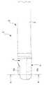
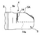
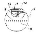
図1から図11は本発明の実施例1に係り、図1は実施例1に係る内視鏡の挿入部の先端部、及び先端カバーの構成を示す斜視図、図2は図1の挿入部の先端部、及び先端カバーをより上部方向から見た場合の斜視図、図3は先端カバーを先端部本体に装着した状態の挿入部、及び先端部の斜視図、図4は図3の挿入部、及び先端部の側面図、図5は先端部本体に先端カバーを装着する前の状態を示す一部破断した先端部本体、及び先端カバーの断面図、図6は先端部本体に先端カバーを装着し係止部によって係止状態にある先端部本体、及び先端カバーの断面図、図7は図4のA−A線断面図、図8から図11は内視鏡の先端カバーの取り外し動作を説明するための説明図である。尚、実施例1では、内視鏡1として、例えば側視型内視鏡を用いた実施例について説明するものとする。Embodiments of the present invention will be described below with reference to the drawings.
Example 1
1 to 11 relate to the first embodiment of the present invention, FIG. 1 is a perspective view showing the configuration of the distal end portion of the insertion portion and the distal end cover of the endoscope according to the first embodiment, and FIG. 2 is the insertion of FIG. FIG. 3 is a perspective view of the distal end portion and the distal end cover when viewed from the upper direction, FIG. 3 is a perspective view of the insertion portion and the distal end portion with the distal end cover mounted on the distal end portion main body, and FIG. 5 is a side view of the insertion portion and the distal end portion, FIG. 5 is a partially cutaway sectional view of the distal end portion main body and the distal end cover showing a state before the distal end cover is attached to the distal end portion main body, and FIG. FIG. 7 is a cross-sectional view of the distal end portion main body and the distal end cover which are attached by the locking portion and are locked by the locking portion, FIG. 7 is a cross-sectional view taken along the line AA of FIG. It is explanatory drawing for demonstrating removal operation | movement. In the first embodiment, an example in which a side-view type endoscope, for example, is used as the
図1に示すように、実施例1の側視型内視鏡(以下、単に内視鏡と称す)1は、術者が把持して種々の操作を行う操作部(図示せず)と、挿入部2とを有して構成されている。 挿入部2は、前記操作部(図示せず)から延設された可撓性を有する可撓管部(図示せず)と、この可撓管部の先端に連設され操作部の操作により左右又は及び上下方向に湾曲可能な湾曲部3と、この湾曲部3の先端に連設された硬性の先端部4と、この先端部4の先端部本体4Aに装着される内視鏡用先端カバー(以下、単に先端カバーと称す)5とを有して構成されている。 As shown in FIG. 1, a side-view endoscope (hereinafter simply referred to as an endoscope) 1 according to the first embodiment includes an operation unit (not shown) that is held by an operator and performs various operations. And an
先端部4は、内視鏡1の挿入部2の先端を構成するもので、内部には例えばステンレス鋼などの金属で構成された先端部本体4Aを有している。
この先端部本体4Aの側面には、観察対象物を照明するための照明光を照射する照明窓6と、観察対象物からの反射光を取入れる観察窓7と、この観察窓7を送気・送水等によって洗滌するための送気送水ノズル8とが配置されている。The
On the side surface of the tip portion
また、先端部本体4Aの中央近傍には、起立台等を配置するためのスペースである収容室4aが形成されている。この収容室4aに対向する先端部本体4Aの挿入部側には、各種処置具の導出口である鉗子口9が設けられている。 A storage chamber 4a, which is a space for arranging an upright stand or the like, is formed in the vicinity of the center of the
尚、図示はしないが、前記照明窓6には光伝送路であるライトガイドが接続され、前記観察窓7には観察光学系が接続されるようになっている。また、この観察光学系には、対物レンズなどを介して撮像素子であるCCD(Charge Coupled Device)が配置されており、このCCDは画像信号を抽出するための回路基板に接続される。そして、前記した図示しないライトガイド、対物レンズ、CCD及び回路基板は、前記先端部本体4Aに形成された収納部(図示せず)内に配置されるようになっている。 Although not shown, a light guide as an optical transmission path is connected to the
また、先端部本体4Aの湾曲部3側の基端部には、先端カバー5の内周面と接触して装着するための接続部4bが形成されている。この接続部4bは、例えば円弧形状に形成されている。 Further, a connecting
さらに、先端部本体4Aの側面には、先端カバー5と係止するための第1の係止溝10が形成されており、逆側の側面にも略同様の第3の係止溝12が形成されている。また、先端部本体4Aの前記収容室4aの下部方向の底面には、先端カバー5と係止するための第2の係止溝11が形成されている。尚、この第2の係止溝11は、開口部を形成している。 Furthermore, a
また、先端部本体4Aの第3の係止溝12には、図2に示すように、先端部4の挿入軸方向に延設されるガイド溝12aが設けられている。このガイド溝12aは、後述する先端カバー5を先端部本体4Aに装着する際にガイドするとともに、この先端カバー5の回転防止を図る機能を有している。 Further, as shown in FIG. 2, a guide groove 12 a extending in the insertion axis direction of the
前記構成の先端部本体4Aには、前記したように絶縁や気密状態確保などの目的で先端カバー5が装着される。この先端カバー5は、例えば柔軟性のある低密度ポリエチレン(LDPE)等の樹脂材を用いてカバー本体部を構成している。尚、この先端カバー5の材質は、低密度ポリエチレンに限定されることはなく、例えばポリスチレン樹脂等の他の合成樹脂やエラストマーを用いて構成しても良く、又はゴム材などを用いて構成しても良い。 As described above, the
先端カバー5は、図1、及び図2に示すように、その後端が開口している開口部5aを有し、この開口部5aから先端部本体4Aの先端が挿入され先端部本体4Aが被さるように構成されている。この開口部5a近傍の縁部の内周面には、テーパー状に形成されたテーパー部5bが設けられている。つまり、このテーパー部5bを設けたことによって、先端カバー5を先端部本体4Aの接続部4bに確実に密着させて装着することができるようになっている。 As shown in FIGS. 1 and 2, the
また、先端カバー5は、照明窓6、及び観察窓7などの配置面側が開口している開口部13を有し、この開口部13からは照明窓6、及び観察窓7が露出されるとともに、各種処置具も導出できるようになっている。 Further, the
本実施例では、先端カバー5と先端部本体4Aとの係止手段として、先端カバー5の両側側面部の内周面には、図1、図2、及び図7に示すように、突起形状の第1の係止部15、第3の係止部17がそれぞれ形成されている。また、先端カバー5の前側の内周面の下部にも、突起形状の第2の係止部16が形成されている。尚、前記第1〜第3の係止部15〜17は、係止部を構成している。 In this embodiment, as a locking means between the
前記先端カバー5を先端部本体4Aに装着する場合、術者は、図5に示すように、内視鏡1の先端部本体4Aの先端に先端カバー5を被せるように、先端部本体4Aのガイド溝12aにガイドされながら先端カバー5を装着させる。 When attaching the
すると、先端カバー5の第1の係止部15は、先端部本体4Aとの接触による押圧力により変形しながら先端部本体4Aの外周上を移動し、その後、図6に示すように、先端部本体4Aの第1の係止溝10に導かれてこの第1の係止溝10に係止される。 Then, the
同時に、逆側の側面部に配置された第3の係止部17は、図示はしないが同様に、先端部本体4Aとの接触による押圧力により変形しながら先端部本体4Aの外周上を移動し、その後、先端部本体4Aの第3の係止溝12に導かれてこの第3の係止溝12に係止される。 At the same time, the
また、先端カバー5の底面に配置された第2の係止部16についても同様に、先端部本体4Aとの接触による押圧力により変形しながら先端部本体4Aの底面の外周上を移動し、その後、先端部本体4Aの開口部を形成している第2の係止溝11に導かれてこの第2の係止溝11に係止される。 Similarly, the
この場合、第1の係止部15と第1の係止溝10とが係止されることによって、先端部本体4Aに対し先端カバー5の挿入軸方向を規制することができる。また、第3の係止部17と第3の係止溝12とが係止されることによって、前記同様に先端部本体4Aに対し先端カバー5の挿入軸方向を規制することができる。 In this case, when the
また、第2の係止部16と第2の係止溝11とが係止されることによって、前記同様に先端部本体4Aに対し先端カバー5の挿入軸方向を規制することができると同時に、先端部本体4Aに対し先端カバー5の挿入軸方向とは鉛直の方向(先端カバー5の外周方向)を規制することができるようになっている。 Further, by locking the
さらに、先端カバー5にはテーパー部5bが設けられているので、図6に示す装着完了状態では、先端カバー5は先端部本体4Aの接続部4bに確実に密着して装着される。
このような構成により、先端部本体4Aに先端カバー5が確実に係止されて装着することが可能である。先端カバー5を先端部本体4Aに装着した場合の挿入部2、及び先端部4の外観が図3、及び図4に示されている。また、図7は図4のA−A線断面図であり、図7においては先端部本体4Aの収容物を省略している。Further, since the
With such a configuration, the
次に、図1から図4を参照しながら、先端カバー5を先端部本体4Aから簡単に取り外すために改良された先端カバー5の具体的な構成について説明する。
図1から図3、及び図4に示すように、先端カバー5の開口部13の一部には、先端カバー5(カバー本体)の外周面に形成された段差部の少なくとも一部である指掛け部5Aが形成されている。この指掛け部5Aは、先端カバー5の縁部である開口部5aから所定距離離間した位置に配されるようになっている。Next, a specific configuration of the
As shown in FIG. 1 to FIG. 3 and FIG. 4, a finger hook which is at least a part of a step portion formed on the outer peripheral surface of the tip cover 5 (cover body) is formed on a part of the
具体的には、指掛け部5Aは、先端カバー5の開口部13を形成する縁部の一部であって、開口部13から露出する照明窓6、及び観察窓7などの配置側とは対向する側の縁部に形成されている。この指掛け部5Aは、例えば先端カバー5を先端部本体4Aから引き裂いて取り外す場合に術者の指によって把持する部分としての役割がある。尚、前記指掛け部5Aは必ずしも前記段差部の一部として形成しなくても良く、縁部の一部であれば良い。 Specifically, the finger-hanging
また、先端カバー5は、前記指掛け部5Aに隣接する所定の範囲に形成され、前記指掛け部5Aを起点に塑性変形することによって前記第1〜第3の係止部15〜17による係止状態を順次解除するための塑性変形部である薄肉部14、及び凹溝14aが設けられている。 Further, the
薄肉部14は、図1から図3、又は図4に示すように、先端カバー5の指掛け部5Aと開口部5aとの間の側面部に設けられており、例えば指掛け部5Aの開口部5a側の基端部から、先端部4の挿入軸方向とは鉛直な下方向に向けて所定距離形成されている。 As shown in FIG. 1 to FIG. 3 or FIG. 4, the thin-
そして、薄肉部14の下部の基端部、又はその近傍から、先端部4の挿入軸方向に向けて先端カバー5の側面部の内周面には、図1から図3に示すように、凹溝14aが形成されている。また、この凹溝14aは、さらに延設されるように、先端部4の挿入軸方向とは平行な水平方向に向けて前面部の内周面に形成されている(図9参照)。さらに、凹溝14aは、さらに延設されるように、先端部4の挿入軸方向に向けて逆側の側面部の内周面に形成されるようになっている(図4参照)。すなわち、前記凹溝14は、薄肉部14の基端部、又は基端部の近傍から先端カバー5の側面部、前面部、逆側の側面部にかけての全周にわたる内周面に形成されている。 And, as shown in FIGS. 1 to 3, on the inner peripheral surface of the side surface portion of the
尚、前記凹溝14aは、前記先端カバー5の内周面全周に設けなくても良く、前記薄肉部14の基端部、又はその基端部近傍から連接するように設けると共に、先端カバー5の内周面全周の内、一部、例えばこの薄肉部14が配置された先端カバー5の側面部の内周面、又は側面部の内周面の一部にかけて設けても良い。 The
このような構成により、先端カバー5は、指掛け部5A近傍に配置される薄肉部14が他の部分に対して肉厚が薄くなるため、この薄肉部14に沿って指掛け部5Aを指で把持しながら簡単に引き裂くことができる。 With such a configuration, the
また、前記凹溝14aが薄肉部14の基端部、又はその基端部近傍から設けられているので、術者がさらに指掛け部5Aを、先端部4の挿入軸方向(前方方向)に移動することにより、凹溝14aについても他の部分に対して肉厚が薄くなっているため、前記薄肉部14の引き裂き動作に連動して、前記同様に簡単に引き裂くことができる。 Further, since the
この場合、本実施例では、術者が凹溝14aに沿って先端部4の挿入軸方向に向けて先端カバー5を引き裂くことにより、まず最初に、第1の係止部15と第1の係止溝10との係止状態が解除され、その後、第2の係止部16と第2の係止溝11との係止状態が解除される。すなわち、この状態では、これら2つ係止部による規制が解除されているので、この状態でも十分に先端カバー5を先端部本体4Aから容易に取り外すことができる。 In this case, in this embodiment, the operator first tears the
そして、さらに術者が凹溝14aに沿って先端部4の挿入軸方向とは鉛直な水平方向に向けて先端カバー5を引き裂くことにより、第2の係止部15と第2の係止溝11との係止状態が完全に解除される。その後、さらに術者が凹溝14aに沿って先端部4の挿入軸方向方向に向けて先端カバー5を引き裂くことにより、第3の係止部17と第3の係止溝12との係止状態が解除される。これにより、先端カバー5は完全に引き裂かれて破壊された状態となるので、容易に先端部本体4Aから取り外すことができる。 Further, when the operator tears the
尚、本実施例において、塑性変形部として薄肉部14と凹溝14aを設けた構成について説明したが、これに限定されるものではなく、例えば先端カバー5の同じ位置に薄肉部14のみを設けて形成しても良く、又は凹溝14aのみを設けて構成しても良い。この場合、凹溝14aは、先端カバー5の内周面、又は外周面、又は内外周面が溝状に形成されたものであっても良い。いずれにしても、これら薄肉部14、及び凹溝14aは、その肉厚が他の部分より薄くなるように形成することが必要である。 In the present embodiment, the configuration in which the
また、前記薄肉部14の縁部の位置は、前記指掛け部5Aの基端側に配置したことについて説明したが、これに限定されるものではなく、例えば薄肉部14を引き裂くことによって第1の係止部15と第1の係止溝10との係止状態が解除される位置であれば、指掛け部5A内に設けても良い。 Moreover, although the position of the edge part of the said
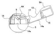
次に、図8から図11を参照しながら、本発明の内視鏡の先端カバー5の取り外し方法を説明する。図8は挿入部の先端本体に先端カバーが装着された状態の先端部の側面図、図9は図8の先端部を前方から見た場合の正面図、図10は術者の指で指掛け部を把持しながら先端カバーを引き裂いた状態の先端部の側面図、図11は図11の状態からさらに先端カバーを引き裂いた状態の先端部の正面図をそれぞれ示している。 Next, a method for removing the
いま、術者は、内視鏡1の使用後に、この内視鏡1の先端部4を構成する先端カバー5を取り外すものとする。このときの挿入部2の先端部4の外観が、図8、及び図9に示されている。 Now, it is assumed that the surgeon removes the
そして、術者は、図10に示すように、先端カバー5の指掛け部5Aを指で把持しながら、先端部4の挿入軸方向とは鉛直な下方向に向けて力を加える。すると、先端カバー5の指掛け部5A近傍には肉厚が他の部分よりも薄い薄肉部14が設けられているので、術者は、図10に示すように、この薄肉部14に沿って指掛け部5Aを指で把持しながら簡単に引き裂くことができる。 Then, as shown in FIG. 10, the surgeon applies a force in a downward direction perpendicular to the insertion axis direction of the
そして、術者は、さらに、指掛け部5Aを把持しながら、先端部4の挿入軸方向(図10に示す矢印A方向)に移動するように力を加える。すると、薄肉部14の基端部、又はその基端部近傍には前記凹溝14aが設けられているので、凹溝14aについても他の部分に対して肉厚が薄くなっているため、前記薄肉部14の引き裂き動作に連動して、前記同様に簡単に引き裂くことができる。 Then, the operator further applies a force so as to move in the insertion axis direction of the distal end portion 4 (the direction of arrow A shown in FIG. 10) while grasping the
この場合、本実施例では、術者が凹溝14aに沿って先端カバー5を引き裂くにつれて、第1〜第3の係止部15〜17と第1〜第3の係止溝10〜12との係止状態が順次解除される。 In this case, in this example, as the surgeon tears the
尚、図10に示す状態では、先端カバー5を側面部の凹溝14aに沿って引き裂いた状態であり、この場合、第1の係止部15と第1の係止溝10との係止状態が解除されることになる。 In the state shown in FIG. 10, the
その後、術者は、さらに前面部、逆側の側面部に配置された凹溝14aに沿って、先端カバー5を引き裂く。すると、先端カバー5は、図10に示す状態から図11に示すように前面部の凹溝14aに沿って引き裂かれた状態になると、さらに第2の係止部16と第2の係止溝11との係止状態が解除される。 Thereafter, the surgeon further tears the
すなわち、この状態においては、先端部本体4Aに対し先端カバー5の挿入軸方向の規制と、先端部本体4Aに対し先端カバー5の挿入軸方向とは鉛直の方向(先端カバー5の外周方向)の規制とを解除することができる。したがって、第1、及び第2の係止部15、16と、第1、及び第2の係止溝10、11との係止状態を解除すれば、先端カバー5を先端部本体4Aから取り外すことができる。 That is, in this state, the restriction in the insertion axis direction of the
そして、さらに、術者が先端カバー5の逆側の側面部(照明窓6、及び観察窓7などが配される側の側面部で、図4参照)の凹溝14aに沿って引き裂くと、図11に示すように、先端カバー5は、完全に凹溝14a全体が引き裂かれた状態になり、破壊された状態となる。この場合、最終的に第3の係止部17と第3の係止溝12との係止状態が解除される。 Further, when the surgeon tears along the
このことにより、先端カバー5は、凹溝14aの全体に渡って引き裂かれて破壊された状態となるので、術者の手によって先端部本体4Aから容易に取り外すことができる。つまり、先端カバー5は、湾曲部3近傍の開口部5aからではなく、上面の開口部13の一部を形成する指掛け部5Aを、器具を用いずに術者の指で把持しながら引き裂き破壊して取り外されるため、湾曲部3の外皮を傷つけることはない。 As a result, the
また、先端カバー5は、テーパー部5bによって先端部本体4Aの接続部4bに密着するように装着されるとともに、第1〜第3の係止部15〜17と第1〜第4の係止溝10〜12との係止によって確実に先端本体部4Aとに係止されるので、使用中に先端カバー5が先端本体部4Aから脱落することを完全に防止することもできる。 The
さらに、先端カバー5は引裂かれて破壊されているので、使用済であることを容易に判断でき、未使用のものと容易に区別することができる。これにより、使用済の先端カバー5を誤って挿着することを防止することができる。また、先端カバー5を使い捨てにすることができるので、常に新しい先端カバー5を挿着することができるので、内視鏡1をより衛生的に使用することができる。また先端カバー5自体の洗浄も不要となるので、内視鏡の洗浄作業も容易になる。 Furthermore, since the
さらに、また、先端カバー5を、先端部本体4Aに設けられたガイド溝12aに沿って装着するので、不用意に回転することはなく円滑に装着することができ、装着性の向上に大きく寄与する。 Furthermore, since the
尚、実施例1では、先端カバー5の塑性変形部(薄肉部14、及び凹溝14a)を、後述する変形例1、及び変形例2に示すように構成しても良い。このような変形例1、及び変形例2を図12から図15を参照しながら説明する。 In the first embodiment, the plastic deformation portion (the
図12、及び図13は実施例1の先端カバー5の塑性変形部の変形例1を示すもので、図12は先端カバーを装着した挿入部の先端部の外観構成を示す斜視図、図13は図12に示す状態から先端カバーを引き裂いた状態の先端部の外観構成を示す斜視図である。尚、図12、及び図13は実施例1の構成要素と同一の構成要素については同一の符号を付して説明を省略し、異なる部分のみを説明する。 12 and 13 show a first modification of the plastic deformation portion of the
図12に示すように、変形例1では、先端カバー50の構成は、実施例1と略同様であるが、塑性変形部を構成する薄肉部14に対向するようにさらにもうひとつの薄肉部14を先端カバー50の側面部に設けている。この新たに設けた薄肉部14は、指掛け部5Aの基端側から、他方の薄肉部14と平行となるように設けられている。
尚、前記2つの薄肉部14は、実施例1の凹溝14aと同じように内周面に設けた凹溝であっても良く、また、外周面、又は内外周面に設けた凹溝であっても良い。As shown in FIG. 12, in the first modification, the configuration of the
The two thin-
また、先端カバー50の前記2つの薄肉部14間の内周面には、先端部本体4Aに設けられた係止溝10Aと係止する係止部15Aが設けられている。先端カバー50が先端部本体4Aに装着した場合には、係止部15Aは先端部本体4Aに設けられた係止溝10Aと係止することによって、先端部本体4Aに対して先端部4の挿入軸方向、及びこの挿入軸方向とは鉛直な方向を規制することができるようになっている。 A locking
このような構成によれば、術者は、図13に示すように、先端カバー50の指掛け部5Aを指で把持しながら、先端部4の挿入軸方向とは鉛直な下方向に向けて力を加えることにより、肉厚が他の部分よりも薄い2つの薄肉部14が設けられているので、これら2つの薄肉部14に沿って指掛け部5Aを指で把持しながら簡単に引き裂くことができる。よって、簡単に先端カバー50を先端部本体4Aから取り外すことができる。 According to such a configuration, as shown in FIG. 13, the surgeon holds the
図14、及び図15は実施例1の先端カバー5の塑性変形部の変形例2を示すもので、図14通常の内視鏡の先端部に先端カバーを装着した場合の先端部の外観構成を示す斜視図、図15は図14に示す状態から先端カバーを引き裂いた状態の先端部の外観構成を示す斜視図である。尚、図14、及び図15は実施例1の構成要素と同一の構成要素については同一の符号を付して説明を省略し、異なる部分のみを説明する。 14 and 15 show a second modification of the plastic deformation portion of the
図14に示すように、変形例2では、実施例1で用いた側視内視鏡1に替えて通常の内視鏡1Aを用いている。周知のように、この内視鏡1Aの先端部4Bの先端面には、2つの照明窓6aと、これら2つの照明窓6a近傍に配される対物レンズなどの観察窓7aと、各種処置具の導出口である鉗子口9aとが設けられている。 As shown in FIG. 14, in the second modification, a
そして、この内視鏡1Aの先端部4Bには、この内視鏡1Aに対応した先端カバー51が装着されている。この先端カバー51は、実施例1と同様に変形部を構成する2つの薄肉部14と、指掛け部51Aとを有して構成されている。 A distal end cover 51 corresponding to the
指掛け部51Aは、実施例1の開口部13の一部ではなく、先端面に配された鉗子口9aの開口部の一部として構成されている。また、2つの薄肉部14は、指掛け部51の所定距離を幅として、鉗子口9aから、先端面、先端カバー51の側面部の後端側まで設けられている。 The
尚、2つの薄肉部14は、併設されているが、必ずしも併設せずともその幅を適宜替えて設けても良い。また、前記2つの薄肉部14は、実施例1の凹溝14aと同じように内周面に設けた凹溝であっても良い。 In addition, although the two
また、図示はしないが、先端カバー50の前記2つの薄肉部14間の内周面に、先端部本体4Bに設けられた係止溝と係止する係止部を設け、先端カバー51を先端部本体4Bに装着した場合には、係止部と先端部本体4Bに設けられた係止溝と係止することによって、先端部本体4Bに対して先端部4の挿入軸方向、及びこの挿入軸方向とは鉛直な方向を規制するようにしても良い。 Although not shown, a locking portion that locks the locking groove provided in the tip body 4B is provided on the inner peripheral surface between the two
このような構成によれば、術者は、図15に示すように、先端カバー51の指掛け部51Aを指で把持しながら、先端部4の挿入軸方向と平行な水平方向に向けて力を加えることにより、肉厚が他の部分よりも薄い2つの薄肉部14が設けられているので、これら2つの薄肉部14に沿って指掛け部51Aを指で把持しながら簡単に引き裂くことができる。よって、簡単に先端カバー51を先端部本体4Bから取り外すことができる。 According to such a configuration, as shown in FIG. 15, the surgeon applies a force toward a horizontal direction parallel to the insertion axis direction of the
尚、本発明に係る実施例1、及び変形例1、2においては、先端カバー5、50、51の塑性変形部は薄肉部14、及び凹溝14aとして構成した場合について説明したが、これに限定されるものではなく、例えば図16に示すようなV溝として構成しても良い。 In the first embodiment and the first and second modifications according to the present invention, the case where the plastic deformation portions of the tip covers 5, 50, 51 are configured as the
また、前記変形部は、図17に示すように、所定幅Lを有し、凹部の平面な底面の肉厚が薄肉である薄肉部14、又は凹溝14aを構成するようにしても良い。この場合、この薄肉部14、又は凹溝14aは、先端カバー5の取り外し時には引き裂かれるものではなく、図18に示すように、肉厚が薄肉である一部分が伸びることにより、隙間を形成することで、先端カバー5を簡単に取り外すことができるように構成しても良い。 In addition, as shown in FIG. 17, the deformable portion may constitute a
また、前記したように塑性変形部を構成する薄肉部14、又は凹溝14aは、先端カバー5の取り外し時には引き裂かれるものではなく、例えば、図19に示すように、先端カバー52の側面部上に設けた指掛け部5Aを囲むように、塑性変形する特性を備えた部材で構成される薄肉部14Aを設けて構成しても良い。勿論、この薄肉部14Aは、内周面に形成された凹溝14aであっても良い。尚、前記塑性変形する特性を備えた薄肉部14Aは、前記指掛け部5Aを囲むような所定範囲内に設けて構成しても良い。 Further, as described above, the thin-
この構成によれば、術者は、先端カバー52の指掛け部5Aを指でつまみながら、先端部4の周面から離れる方向に向けて力を加えることにより、塑性変形する特性を備えた薄肉部14Aが設けられているので、図20に示すように、指掛け部5Aを囲む薄肉部14A(又は、薄肉部14を用いて形成された部分)を引き裂くものではなく簡単に塑性変形することができる。よって、隙間が形成することにより簡単に先端カバー52を先端部本体から取り外すことができる。 According to this configuration, the surgeon applies a force toward the direction away from the peripheral surface of the
以上の実施例に記載した発明は、その実施例、及び変形例に限ることなく、その他、実施段階ではその要旨を逸脱しない範囲で種々の変形を実施し得ることが可能である。さらに、前記実施例には、種々の段階の発明が含まれており、開示される複数の構成要件における適宜な組合せにより種々の発明が抽出され得る。 The invention described in the above embodiments is not limited to the embodiments and modifications, and various modifications can be made without departing from the scope of the invention in the implementation stage. Further, the embodiments include inventions at various stages, and various inventions can be extracted by appropriately combining a plurality of disclosed constituent elements.
例えば、実施例に示される全構成要件から幾つかの構成要件が削除されても、発明が解決しようとする課題の欄で述べた課題が解決でき、発明の効果で述べられている効果が得られる場合には、この構成要件が削除された構成が発明として抽出され得る。 For example, even if some constituent elements are deleted from all the constituent elements shown in the embodiment, the problems described in the column of problems to be solved by the invention can be solved, and the effects described in the effects of the invention can be obtained. In such a case, a configuration in which this configuration requirement is deleted can be extracted as an invention.
1…内視鏡(側視内視鏡)
2…挿入部
3…湾曲部
4a…収容室
4b…接続部
4…先端部
4A…先端部本体
5a…開口部
5b…テーパー部
5…先端カバー
5A…指掛け部
6…照明窓
7…観察窓
8…送気送水ノズル
9…鉗子口
10…第1の係止溝
11…第2の係止溝
12a…ガイド溝
12…第3の係止溝
13…開口部
14a…凹溝
14…薄肉部
15…第1の係止部
16…第2の係止部
17…第3の係止部1. Endoscope (side view endoscope)
DESCRIPTION OF
Claims (7)
Translated fromJapanese前記カバー本体部の前記開口部の縁部から所定距離離間した位置に設けられた指掛け部と、
前記指掛け部の近傍に配置され、前記カバー本体部の所定方向に沿って形成された塑性変形部と、
前記塑性変形部の内周面側に設けられ、前記先端部本体を係止するための複数の係止部と、を有し、
前記塑性変形部は、前記指掛け部を起点に塑性変形させることによって、前記係止部による前記先端部本体に対する係止状態を解除するための隙間を前記カバー本体部と前記先端部本体との間に形成するものであって、前記指掛け部を起点に変形される変形状態に応じて、複数の前記係止部の前記先端部本体に対する係止状態を順次解除することを特徴とする内視鏡用先端カバー。A tip cover having a cover body portion covering at least a part of the outer peripheral portion of the tip portion main body provided on the tip side of the insertion portion of the endoscope, and an opening through which the tip portion body is inserted,
A finger hook provided at a position spaced a predetermined distance from an edge of the opening of the cover body;
A plastic deformation portion disposed in the vicinity of the finger-hanging portion and formed along a predetermined direction of the cover body portion;
Aplurality of locking portions provided on the inner peripheral surface side of the plastic deformation portion, for locking the tip portion main body,
The plastic deformation portion causesa gap between the cover main body portion and the front end portion main body to release a locking state with respect to the front end portion main body by the locking portion by plastically deforming with the finger-hanging portion as a starting point.An endoscopewhich is formed in the above-described manner andsequentially releases the locking state of the plurality of locking portions with respect to the distal end body according to a deformed state where the finger-hanging portion is used as a starting point. Tip cover.
前記内視鏡用カバーが装着される、挿入部の先端側に硬質な先端部本体を有する内視鏡と、
を具備したことを特徴とする内視鏡装置。An endoscope tip cover according to any one of claims 1 to 5,
An endoscope having a rigid distal end main body on the distal end side of the insertion portion, to which the endoscope cover is attached;
An endoscopeapparatus characterizedby comprising:
前記内視鏡用カバーが装着される、挿入部の先端側に硬質な先端部本体を有する内視鏡と、を具備した内視鏡装置における、前記内視鏡の先端カバーの取り外し方法であって、
前記指掛け部を起点に前記塑性変形部を塑性変形させる塑性変形手順と、
前記塑性変形手順により前記係止部による前記先端部本体に対する係止状態を解除する係止解除手順と、
を含み、
前記係止解除手順は、前記指掛け部を起点に塑性変形させることによって前記カバー本体と前記先端部本体との間に隙間を形成して前記係止部による前記先端部本体に対する係止状態を解除し、
前記塑性変形手順は、前記指掛け部を起点に変形される前記塑性変形部の変形状態に応じて、複数の前記係止部の前記先端部本体に対する係止状態を順次解除することを特徴とする内視鏡の先端カバーの取り外し方法。An endoscope tip cover according to any one of claims 1 to 5,
An endoscope apparatus comprising: an endoscope having a hard distal end main body on a distal end side of an insertion portion to which the endoscope cover is attached; and a method for removing the distal end cover of the endoscope. And
A plastic deformation procedure for plastically deforming the plastic deformation portion starting from the finger-hanging portion;
An unlocking procedure for releasing the locking state of the distal end portion body by the locking portion by the plastic deformation procedure,
Including
In the unlocking procedure, a clearance is formed between the cover main body and the distal end portion main body by plastically deforming from the finger hanging portion as a starting point, and the locked state of the distal end portion main body by the locking portion is released. And
The plastic deformation procedure sequentially releases the locking state of the plurality of locking portions with respect to the distal end body according to the deformation state of the plastic deformation portion that is deformed starting from the finger-hanging portion.How to remove the tip cover of the endoscope.
Priority Applications (6)
| Application Number | Priority Date | Filing Date | Title |
|---|---|---|---|
| JP2006121209AJP4855824B2 (en) | 2006-04-25 | 2006-04-25 | Endoscope tip cover, endoscope device, and method of removing endoscope tip cover in endoscope device |
| EP07007880AEP1849397B1 (en) | 2006-04-25 | 2007-04-18 | Endoscope distal end cover and endoscope including the same |
| DE602007007386TDE602007007386D1 (en) | 2006-04-25 | 2007-04-18 | Endoscope distal end cover and endoscope provided therewith |
| CNU2007201428271UCN201055370Y (en) | 2006-04-25 | 2007-04-23 | Front end cover for endoscope and endoscope using the same |
| CN2007101044685ACN101061940B (en) | 2006-04-25 | 2007-04-23 | Endoscope tip cover, endoscope using the tip cover, and method for removing the tip cover of the endoscope |
| US11/789,231US8038604B2 (en) | 2006-04-25 | 2007-04-24 | Endoscope distal end cover, endoscope including the same, and method for removing endoscope distal end cover |
Applications Claiming Priority (1)
| Application Number | Priority Date | Filing Date | Title |
|---|---|---|---|
| JP2006121209AJP4855824B2 (en) | 2006-04-25 | 2006-04-25 | Endoscope tip cover, endoscope device, and method of removing endoscope tip cover in endoscope device |
Publications (2)
| Publication Number | Publication Date |
|---|---|
| JP2007289434A JP2007289434A (en) | 2007-11-08 |
| JP4855824B2true JP4855824B2 (en) | 2012-01-18 |
Family
ID=38283014
Family Applications (1)
| Application Number | Title | Priority Date | Filing Date |
|---|---|---|---|
| JP2006121209AExpired - Fee RelatedJP4855824B2 (en) | 2006-04-25 | 2006-04-25 | Endoscope tip cover, endoscope device, and method of removing endoscope tip cover in endoscope device |
Country Status (5)
| Country | Link |
|---|---|
| US (1) | US8038604B2 (en) |
| EP (1) | EP1849397B1 (en) |
| JP (1) | JP4855824B2 (en) |
| CN (2) | CN201055370Y (en) |
| DE (1) | DE602007007386D1 (en) |
Cited By (5)
| Publication number | Priority date | Publication date | Assignee | Title |
|---|---|---|---|---|
| US10271715B2 (en) | 2015-07-15 | 2019-04-30 | Olympus Coporation | Distal end cover of endoscope and endoscope |
| US10820785B2 (en) | 2015-07-06 | 2020-11-03 | Olympus Corporation | Cover removal tool for endoscope |
| US11147433B2 (en) | 2016-12-02 | 2021-10-19 | Olympus Corporation | Distal end cover for endoscope |
| US11419489B2 (en) | 2018-01-31 | 2022-08-23 | Olympus Corporation | Cleaning tool for insertion instrument |
| US12089810B2 (en) | 2022-03-04 | 2024-09-17 | Olympus Medical Systems Corp. | Distal end cover and endoscope |
Families Citing this family (71)
| Publication number | Priority date | Publication date | Assignee | Title |
|---|---|---|---|---|
| JP4855824B2 (en)* | 2006-04-25 | 2012-01-18 | オリンパスメディカルシステムズ株式会社 | Endoscope tip cover, endoscope device, and method of removing endoscope tip cover in endoscope device |
| US9872609B2 (en) | 2009-06-18 | 2018-01-23 | Endochoice Innovation Center Ltd. | Multi-camera endoscope |
| US9713417B2 (en) | 2009-06-18 | 2017-07-25 | Endochoice, Inc. | Image capture assembly for use in a multi-viewing elements endoscope |
| US12137873B2 (en) | 2009-06-18 | 2024-11-12 | Endochoice, Inc. | Compact multi-viewing element endoscope system |
| US9492063B2 (en) | 2009-06-18 | 2016-11-15 | Endochoice Innovation Center Ltd. | Multi-viewing element endoscope |
| US9706903B2 (en) | 2009-06-18 | 2017-07-18 | Endochoice, Inc. | Multiple viewing elements endoscope system with modular imaging units |
| US9101287B2 (en) | 2011-03-07 | 2015-08-11 | Endochoice Innovation Center Ltd. | Multi camera endoscope assembly having multiple working channels |
| US9101268B2 (en) | 2009-06-18 | 2015-08-11 | Endochoice Innovation Center Ltd. | Multi-camera endoscope |
| WO2010146587A1 (en) | 2009-06-18 | 2010-12-23 | Peer Medical Ltd. | Multi-camera endoscope |
| US10165929B2 (en) | 2009-06-18 | 2019-01-01 | Endochoice, Inc. | Compact multi-viewing element endoscope system |
| US11864734B2 (en) | 2009-06-18 | 2024-01-09 | Endochoice, Inc. | Multi-camera endoscope |
| US9402533B2 (en) | 2011-03-07 | 2016-08-02 | Endochoice Innovation Center Ltd. | Endoscope circuit board assembly |
| US9901244B2 (en) | 2009-06-18 | 2018-02-27 | Endochoice, Inc. | Circuit board assembly of a multiple viewing elements endoscope |
| US11547275B2 (en) | 2009-06-18 | 2023-01-10 | Endochoice, Inc. | Compact multi-viewing element endoscope system |
| US8926502B2 (en) | 2011-03-07 | 2015-01-06 | Endochoice, Inc. | Multi camera endoscope having a side service channel |
| US11278190B2 (en) | 2009-06-18 | 2022-03-22 | Endochoice, Inc. | Multi-viewing element endoscope |
| US9642513B2 (en) | 2009-06-18 | 2017-05-09 | Endochoice Inc. | Compact multi-viewing element endoscope system |
| JP5389721B2 (en)* | 2010-03-31 | 2014-01-15 | 富士フイルム株式会社 | Endoscope hood |
| WO2011124149A1 (en)* | 2010-04-09 | 2011-10-13 | 姜守美 | Disposable protection assembly for endoscope |
| US12220105B2 (en) | 2010-06-16 | 2025-02-11 | Endochoice, Inc. | Circuit board assembly of a multiple viewing elements endoscope |
| EP2596738B1 (en) | 2010-09-10 | 2014-09-03 | Olympus Medical Systems Corp. | Endoscope |
| EP2618718B1 (en) | 2010-09-20 | 2020-04-15 | EndoChoice Innovation Center Ltd. | Multi-camera endoscope having fluid channels |
| US9560953B2 (en) | 2010-09-20 | 2017-02-07 | Endochoice, Inc. | Operational interface in a multi-viewing element endoscope |
| CN103403605A (en) | 2010-10-28 | 2013-11-20 | 恩多巧爱思创新中心有限公司 | Optical systems for multi-sensor endoscopes |
| US12204087B2 (en) | 2010-10-28 | 2025-01-21 | Endochoice, Inc. | Optical systems for multi-sensor endoscopes |
| CN107361721B (en) | 2010-12-09 | 2019-06-18 | 恩多巧爱思创新中心有限公司 | Flexible electronic circuit boards for multi-camera endoscopes |
| US11889986B2 (en) | 2010-12-09 | 2024-02-06 | Endochoice, Inc. | Flexible electronic circuit board for a multi-camera endoscope |
| US9320419B2 (en) | 2010-12-09 | 2016-04-26 | Endochoice Innovation Center Ltd. | Fluid channeling component of a multi-camera endoscope |
| EP2672878B1 (en)* | 2011-02-07 | 2017-11-22 | Endochoice Innovation Center Ltd. | Multi-element cover for a multi-camera endoscope |
| WO2013084561A1 (en)* | 2011-12-08 | 2013-06-13 | オリンパスメディカルシステムズ株式会社 | Endoscope |
| CA2798716A1 (en) | 2011-12-13 | 2013-06-13 | Peermedical Ltd. | Removable tip endoscope |
| EP2604172B1 (en) | 2011-12-13 | 2015-08-12 | EndoChoice Innovation Center Ltd. | Rotatable connector for an endoscope |
| US9560954B2 (en) | 2012-07-24 | 2017-02-07 | Endochoice, Inc. | Connector for use with endoscope |
| JP5683614B2 (en)* | 2013-01-08 | 2015-03-11 | 富士フイルム株式会社 | Ultrasound endoscope |
| JP5657843B1 (en)* | 2013-02-07 | 2015-01-21 | オリンパスメディカルシステムズ株式会社 | Endoscope operation unit structure |
| US9986899B2 (en) | 2013-03-28 | 2018-06-05 | Endochoice, Inc. | Manifold for a multiple viewing elements endoscope |
| US9993142B2 (en) | 2013-03-28 | 2018-06-12 | Endochoice, Inc. | Fluid distribution device for a multiple viewing elements endoscope |
| US10499794B2 (en) | 2013-05-09 | 2019-12-10 | Endochoice, Inc. | Operational interface in a multi-viewing element endoscope |
| US11234581B2 (en)* | 2014-05-02 | 2022-02-01 | Endochoice, Inc. | Elevator for directing medical tool |
| WO2015174445A1 (en)* | 2014-05-15 | 2015-11-19 | オリンパス株式会社 | Fixing mechanism and endoscope having fixing mechanism |
| WO2016021233A1 (en)* | 2014-08-06 | 2016-02-11 | オリンパス株式会社 | Endoscope |
| WO2016021234A1 (en)* | 2014-08-07 | 2016-02-11 | オリンパス株式会社 | Tip structure for endoscope |
| WO2016040128A1 (en)* | 2014-09-10 | 2016-03-17 | Intuitive Surgical Operations, Inc. | Devices, systems, and methods using mating catheter tips and tools |
| WO2016194450A1 (en)* | 2015-06-02 | 2016-12-08 | オリンパス株式会社 | Endoscope |
| JP6275337B2 (en)* | 2015-06-30 | 2018-02-07 | オリンパス株式会社 | Endoscope provided with insertion device and insertion device |
| DE102015113020B4 (en)* | 2015-08-07 | 2023-10-05 | Digital Endoscopy Gmbh | Endoscope head |
| JP6266194B2 (en)* | 2016-01-14 | 2018-01-24 | オリンパス株式会社 | Endoscope cover, endoscope and cover unit |
| JP6177487B1 (en)* | 2016-01-14 | 2017-08-09 | オリンパス株式会社 | Endoscope cover, endoscope, cover unit and endoscope unit |
| EP3403566A4 (en)* | 2016-01-14 | 2019-09-18 | Olympus Corporation | Endoscope cover, endoscope, cover unit, and endoscope unit |
| CN105662327A (en)* | 2016-01-29 | 2016-06-15 | 姜克让 | Jacketed endoscope |
| WO2017163675A1 (en)* | 2016-03-23 | 2017-09-28 | オリンパス株式会社 | Endoscope and endoscope system |
| US20190117045A1 (en)* | 2016-07-19 | 2019-04-25 | Hoya Corporation | Endoscope cap, endoscope and method of manufacturing endoscope cap |
| DE112017003629T5 (en)* | 2016-07-19 | 2019-04-11 | Hoya Corporation | Endoscope cap, endoscope and method of making an endoscope cap |
| JP6387479B2 (en)* | 2016-09-16 | 2018-09-05 | オリンパス株式会社 | Endoscope cover and endoscope |
| CN109715030B (en)* | 2016-10-14 | 2022-05-06 | Hoya株式会社 | Endoscope lens cap and sterilization method thereof |
| CN109788887B (en)* | 2016-10-14 | 2022-02-18 | Hoya株式会社 | Endoscope and lens cap for endoscope |
| JPWO2018070515A1 (en)* | 2016-10-14 | 2019-07-04 | Hoya株式会社 | Endoscope Cap, Elevator, Endoscope, Method of Removing Endoscope Cap, and Method of Manufacturing Endoscope Cap |
| CN109757097B (en)* | 2016-10-14 | 2022-02-18 | Hoya株式会社 | Stand and endoscope |
| JP6751151B2 (en) | 2016-10-14 | 2020-09-02 | Hoya株式会社 | Endoscope cap, endoscope and method for removing endoscope cap |
| CN107997732B (en)* | 2016-10-28 | 2020-10-16 | 杭州微视医疗科技有限公司 | Endoscope and have endoscope hose assembly of disposable sleeve |
| CN106691361B (en)* | 2017-01-19 | 2020-10-23 | 深圳开立生物医疗科技股份有限公司 | Endoscope headstock and endoscope |
| CN110381800B (en)* | 2017-03-31 | 2021-11-16 | 奥林巴斯株式会社 | Front end cover of endoscope |
| CN110475500B (en)* | 2017-04-11 | 2022-01-28 | 奥林巴斯株式会社 | Cap and endoscope system |
| USD870280S1 (en) | 2017-05-26 | 2019-12-17 | Medivators Inc. | Fitting for an endoscope device having protuberances |
| USD870281S1 (en) | 2017-05-26 | 2019-12-17 | Medivators Inc. | Fitting for an endoscope device having a tab |
| WO2019116637A1 (en)* | 2017-12-12 | 2019-06-20 | オリンパス株式会社 | Endoscope, distal end cover, and endoscope system |
| JP2020000679A (en)* | 2018-06-29 | 2020-01-09 | Hoya株式会社 | Endoscope cap |
| JP7545892B2 (en)* | 2018-07-06 | 2024-09-05 | Hoya株式会社 | Endoscopy |
| KR20250029943A (en)* | 2022-07-04 | 2025-03-05 | 마이크로스티어 엘티디 | Endoscope with shovel |
| CN116849589A (en)* | 2023-08-10 | 2023-10-10 | 深圳开立生物医疗科技股份有限公司 | Disposable head end cap and endoscope |
| WO2025178039A1 (en)* | 2024-02-22 | 2025-08-28 | オリンパスメディカルシステムズ株式会社 | Endoscope cover attachment system and endoscope cover attachment method |
Family Cites Families (13)
| Publication number | Priority date | Publication date | Assignee | Title |
|---|---|---|---|---|
| DE2952705C2 (en)* | 1979-12-29 | 1982-03-18 | Schott Glaswerke, 6500 Mainz | Optical glass with the optical position n ↓ D ↓ is 1.62 + - (1.5 times 10-2), V ↓ D ↓ is 59.5 + -1.0, with high chemical resistance and low tendency to crystallize based on the known system SiO ↓ 2 ↓ -B ↓ 2 ↓ O ↓ 3 ↓ -La ↓ 2 ↓ O ↓ 3 ↓ -SrO- |
| US4881810A (en)* | 1986-11-10 | 1989-11-21 | Olympus Optical Co., Ltd. | Endoscope with a removable cover member |
| US5104379A (en)* | 1989-04-03 | 1992-04-14 | Olympus Optical Co., Ltd. | Medical instrument and valve to be mounted on a mount piece of that instrument |
| JP3379821B2 (en)* | 1994-05-31 | 2003-02-24 | オリンパス光学工業株式会社 | Endoscope |
| JPH08140924A (en)* | 1994-11-16 | 1996-06-04 | Asahi Optical Co Ltd | End of endoscope |
| US5730701A (en)* | 1995-09-12 | 1998-03-24 | Olympus Optical Co., Ltd. | Endoscope |
| US5865726A (en)* | 1996-03-27 | 1999-02-02 | Asahi Kogaku Kogyo Kabushiki Kaisha | Front end structure of side-view type endoscope |
| US5860913A (en)* | 1996-05-16 | 1999-01-19 | Olympus Optical Co., Ltd. | Endoscope whose distal cover can be freely detachably attached to main distal part thereof with high positioning precision |
| JP3548333B2 (en)* | 1996-05-16 | 2004-07-28 | オリンパス株式会社 | Endoscope |
| JP2003102668A (en)* | 2001-09-28 | 2003-04-08 | Fuji Photo Optical Co Ltd | Tip cap for endoscope |
| JP3826045B2 (en)* | 2002-02-07 | 2006-09-27 | オリンパス株式会社 | Endoscope hood |
| JP4855824B2 (en)* | 2006-04-25 | 2012-01-18 | オリンパスメディカルシステムズ株式会社 | Endoscope tip cover, endoscope device, and method of removing endoscope tip cover in endoscope device |
| US8747304B2 (en)* | 2006-10-31 | 2014-06-10 | Ethicon Endo-Surgery, Inc. | Attachment apparatus for an endoscope |
- 2006
- 2006-04-25JPJP2006121209Apatent/JP4855824B2/ennot_activeExpired - Fee Related
- 2007
- 2007-04-18DEDE602007007386Tpatent/DE602007007386D1/enactiveActive
- 2007-04-18EPEP07007880Apatent/EP1849397B1/ennot_activeNot-in-force
- 2007-04-23CNCNU2007201428271Upatent/CN201055370Y/ennot_activeExpired - Fee Related
- 2007-04-23CNCN2007101044685Apatent/CN101061940B/ennot_activeExpired - Fee Related
- 2007-04-24USUS11/789,231patent/US8038604B2/ennot_activeExpired - Fee Related
Cited By (5)
| Publication number | Priority date | Publication date | Assignee | Title |
|---|---|---|---|---|
| US10820785B2 (en) | 2015-07-06 | 2020-11-03 | Olympus Corporation | Cover removal tool for endoscope |
| US10271715B2 (en) | 2015-07-15 | 2019-04-30 | Olympus Coporation | Distal end cover of endoscope and endoscope |
| US11147433B2 (en) | 2016-12-02 | 2021-10-19 | Olympus Corporation | Distal end cover for endoscope |
| US11419489B2 (en) | 2018-01-31 | 2022-08-23 | Olympus Corporation | Cleaning tool for insertion instrument |
| US12089810B2 (en) | 2022-03-04 | 2024-09-17 | Olympus Medical Systems Corp. | Distal end cover and endoscope |
Also Published As
| Publication number | Publication date |
|---|---|
| US20070246506A1 (en) | 2007-10-25 |
| JP2007289434A (en) | 2007-11-08 |
| EP1849397B1 (en) | 2010-06-30 |
| CN101061940B (en) | 2011-06-22 |
| EP1849397A1 (en) | 2007-10-31 |
| CN201055370Y (en) | 2008-05-07 |
| CN101061940A (en) | 2007-10-31 |
| DE602007007386D1 (en) | 2010-08-12 |
| US8038604B2 (en) | 2011-10-18 |
Similar Documents
| Publication | Publication Date | Title |
|---|---|---|
| JP4855824B2 (en) | Endoscope tip cover, endoscope device, and method of removing endoscope tip cover in endoscope device | |
| JP6099851B1 (en) | Endoscope tip cover and endoscope | |
| US6916284B2 (en) | Endoscope hood | |
| JP6188993B2 (en) | Endoscope cover removal jig and endoscope system | |
| JP6184657B1 (en) | Cover unit and endoscope unit | |
| JP6368888B1 (en) | Endoscope tip cover | |
| JP6387479B2 (en) | Endoscope cover and endoscope | |
| CN100584266C (en) | plug for endoscope | |
| JP6177487B1 (en) | Endoscope cover, endoscope, cover unit and endoscope unit | |
| JP6266194B2 (en) | Endoscope cover, endoscope and cover unit | |
| JP6165400B1 (en) | Endoscope system, cover removal tool | |
| JP2003102668A (en) | Tip cap for endoscope | |
| JP6756055B2 (en) | Endoscope hood removal jig and hood and hood removal jig set | |
| JP4986223B2 (en) | Endoscope tip cap and endoscope | |
| JP4594670B2 (en) | Endoscopic treatment tool stopper | |
| JP2019115564A (en) | Endoscope, raising base, cap for endoscope, attachment method of endoscope cap, and detachment method of endoscope cap | |
| JP2009219572A (en) | Hood for endoscope | |
| JP2019115562A (en) | Raising base, endoscope, and attachment method of raising base | |
| JP2008099745A (en) | Ultrasound endoscope balloon removal device | |
| JP4009599B2 (en) | Endoscopic treatment tool stopper | |
| JP3725849B2 (en) | Endoscope | |
| JP4184823B2 (en) | Endoscopic treatment tool | |
| JP2012200524A (en) | Plug body and endoscope | |
| JP3806546B2 (en) | Endoscope | |
| JP4280529B2 (en) | Endoscope tip cap and endoscope tip |
Legal Events
| Date | Code | Title | Description |
|---|---|---|---|
| A621 | Written request for application examination | Free format text:JAPANESE INTERMEDIATE CODE: A621 Effective date:20090219 | |
| A977 | Report on retrieval | Free format text:JAPANESE INTERMEDIATE CODE: A971007 Effective date:20110609 | |
| A131 | Notification of reasons for refusal | Free format text:JAPANESE INTERMEDIATE CODE: A131 Effective date:20110614 | |
| A521 | Request for written amendment filed | Free format text:JAPANESE INTERMEDIATE CODE: A523 Effective date:20110803 | |
| TRDD | Decision of grant or rejection written | ||
| A01 | Written decision to grant a patent or to grant a registration (utility model) | Free format text:JAPANESE INTERMEDIATE CODE: A01 Effective date:20111025 | |
| A01 | Written decision to grant a patent or to grant a registration (utility model) | Free format text:JAPANESE INTERMEDIATE CODE: A01 | |
| A61 | First payment of annual fees (during grant procedure) | Free format text:JAPANESE INTERMEDIATE CODE: A61 Effective date:20111027 | |
| FPAY | Renewal fee payment (event date is renewal date of database) | Free format text:PAYMENT UNTIL: 20141104 Year of fee payment:3 | |
| R151 | Written notification of patent or utility model registration | Ref document number:4855824 Country of ref document:JP Free format text:JAPANESE INTERMEDIATE CODE: R151 | |
| FPAY | Renewal fee payment (event date is renewal date of database) | Free format text:PAYMENT UNTIL: 20141104 Year of fee payment:3 | |
| S111 | Request for change of ownership or part of ownership | Free format text:JAPANESE INTERMEDIATE CODE: R313111 | |
| R350 | Written notification of registration of transfer | Free format text:JAPANESE INTERMEDIATE CODE: R350 | |
| S531 | Written request for registration of change of domicile | Free format text:JAPANESE INTERMEDIATE CODE: R313531 | |
| R350 | Written notification of registration of transfer | Free format text:JAPANESE INTERMEDIATE CODE: R350 | |
| R250 | Receipt of annual fees | Free format text:JAPANESE INTERMEDIATE CODE: R250 | |
| R250 | Receipt of annual fees | Free format text:JAPANESE INTERMEDIATE CODE: R250 | |
| R250 | Receipt of annual fees | Free format text:JAPANESE INTERMEDIATE CODE: R250 | |
| R250 | Receipt of annual fees | Free format text:JAPANESE INTERMEDIATE CODE: R250 | |
| R250 | Receipt of annual fees | Free format text:JAPANESE INTERMEDIATE CODE: R250 | |
| LAPS | Cancellation because of no payment of annual fees |