JP4853516B2 - Safety needle assembly - Google Patents
Safety needle assemblyDownload PDFInfo
- Publication number
- JP4853516B2 JP4853516B2JP2008513312AJP2008513312AJP4853516B2JP 4853516 B2JP4853516 B2JP 4853516B2JP 2008513312 AJP2008513312 AJP 2008513312AJP 2008513312 AJP2008513312 AJP 2008513312AJP 4853516 B2JP4853516 B2JP 4853516B2
- Authority
- JP
- Japan
- Prior art keywords
- needle
- tip
- opening
- hub
- protection
- Prior art date
- Legal status (The legal status is an assumption and is not a legal conclusion. Google has not performed a legal analysis and makes no representation as to the accuracy of the status listed.)
- Active
Links
- 230000001012protectorEffects0.000claimsdescription23
- 238000005452bendingMethods0.000claimsdescription11
- 230000002265preventionEffects0.000claimsdescription9
- 238000005520cutting processMethods0.000claimsdescription4
- 239000007787solidSubstances0.000claims1
- 230000001681protective effectEffects0.000description13
- 208000012266Needlestick injuryDiseases0.000description3
- 238000009434installationMethods0.000description3
- 238000003825pressingMethods0.000description3
- 230000003796beautyEffects0.000description2
- 210000001124body fluidAnatomy0.000description2
- 239000010839body fluidSubstances0.000description2
- 208000015181infectious diseaseDiseases0.000description2
- 238000000034methodMethods0.000description2
- 210000004369bloodAnatomy0.000description1
- 239000008280bloodSubstances0.000description1
- 210000000078clawAnatomy0.000description1
- 239000003814drugSubstances0.000description1
- 230000005484gravityEffects0.000description1
- 208000006454hepatitisDiseases0.000description1
- 231100000283hepatitisToxicity0.000description1
- 238000002347injectionMethods0.000description1
- 239000007924injectionSubstances0.000description1
- 238000003780insertionMethods0.000description1
- 230000037431insertionEffects0.000description1
- 239000007788liquidSubstances0.000description1
- 238000004519manufacturing processMethods0.000description1
- 239000000463materialSubstances0.000description1
- 239000008155medical solutionSubstances0.000description1
- 230000000149penetrating effectEffects0.000description1
- 238000006748scratchingMethods0.000description1
- 230000002393scratching effectEffects0.000description1
- 238000000926separation methodMethods0.000description1
Images


Classifications
- A—HUMAN NECESSITIES
- A61—MEDICAL OR VETERINARY SCIENCE; HYGIENE
- A61M—DEVICES FOR INTRODUCING MEDIA INTO, OR ONTO, THE BODY; DEVICES FOR TRANSDUCING BODY MEDIA OR FOR TAKING MEDIA FROM THE BODY; DEVICES FOR PRODUCING OR ENDING SLEEP OR STUPOR
- A61M5/00—Devices for bringing media into the body in a subcutaneous, intra-vascular or intramuscular way; Accessories therefor, e.g. filling or cleaning devices, arm-rests
- A61M5/14—Infusion devices, e.g. infusing by gravity; Blood infusion; Accessories therefor
- A61M5/158—Needles for infusions; Accessories therefor, e.g. for inserting infusion needles, or for holding them on the body
- A61M2005/1581—Right-angle needle-type devices
- A—HUMAN NECESSITIES
- A61—MEDICAL OR VETERINARY SCIENCE; HYGIENE
- A61M—DEVICES FOR INTRODUCING MEDIA INTO, OR ONTO, THE BODY; DEVICES FOR TRANSDUCING BODY MEDIA OR FOR TAKING MEDIA FROM THE BODY; DEVICES FOR PRODUCING OR ENDING SLEEP OR STUPOR
- A61M5/00—Devices for bringing media into the body in a subcutaneous, intra-vascular or intramuscular way; Accessories therefor, e.g. filling or cleaning devices, arm-rests
- A61M5/178—Syringes
- A61M5/31—Details
- A61M5/32—Needles; Details of needles pertaining to their connection with syringe or hub; Accessories for bringing the needle into, or holding the needle on, the body; Devices for protection of needles
- A61M5/3205—Apparatus for removing or disposing of used needles or syringes, e.g. containers; Means for protection against accidental injuries from used needles
- A61M5/321—Means for protection against accidental injuries by used needles
- A61M5/3243—Means for protection against accidental injuries by used needles being axially-extensible, e.g. protective sleeves coaxially slidable on the syringe barrel
- A61M5/3245—Constructional features thereof, e.g. to improve manipulation or functioning
- A61M2005/3247—Means to impede repositioning of protection sleeve from needle covering to needle uncovering position
- A61M2005/3249—Means to disalign the needle tip and the distal needle passage of a needle protection sleeve
- A—HUMAN NECESSITIES
- A61—MEDICAL OR VETERINARY SCIENCE; HYGIENE
- A61M—DEVICES FOR INTRODUCING MEDIA INTO, OR ONTO, THE BODY; DEVICES FOR TRANSDUCING BODY MEDIA OR FOR TAKING MEDIA FROM THE BODY; DEVICES FOR PRODUCING OR ENDING SLEEP OR STUPOR
- A61M5/00—Devices for bringing media into the body in a subcutaneous, intra-vascular or intramuscular way; Accessories therefor, e.g. filling or cleaning devices, arm-rests
- A61M5/178—Syringes
- A61M5/31—Details
- A61M5/32—Needles; Details of needles pertaining to their connection with syringe or hub; Accessories for bringing the needle into, or holding the needle on, the body; Devices for protection of needles
- A61M5/3205—Apparatus for removing or disposing of used needles or syringes, e.g. containers; Means for protection against accidental injuries from used needles
- A61M5/321—Means for protection against accidental injuries by used needles
- A61M5/3243—Means for protection against accidental injuries by used needles being axially-extensible, e.g. protective sleeves coaxially slidable on the syringe barrel
- A61M5/3275—Means for protection against accidental injuries by used needles being axially-extensible, e.g. protective sleeves coaxially slidable on the syringe barrel being connected to the needle hub or syringe by radially deflectable members, e.g. longitudinal slats, cords or bands
Landscapes
- Health & Medical Sciences (AREA)
- Vascular Medicine (AREA)
- Engineering & Computer Science (AREA)
- Anesthesiology (AREA)
- Biomedical Technology (AREA)
- Heart & Thoracic Surgery (AREA)
- Hematology (AREA)
- Life Sciences & Earth Sciences (AREA)
- Animal Behavior & Ethology (AREA)
- General Health & Medical Sciences (AREA)
- Public Health (AREA)
- Veterinary Medicine (AREA)
- Infusion, Injection, And Reservoir Apparatuses (AREA)
Description
Translated fromJapanese本発明は、針先を保護する安全針組立体に関し、さらに湾曲部を有する針を用いた安全針組立体に関し、詳しくは皮下埋め込み型カテーテルアクセスポート用穿刺針であるフーバー針組立体に関する。さらに詳しくはカテーテルアクセスポートに穿刺したフーバー針組立体を抜去した際に、針の先端を覆うことが可能である、針刺し事故防止のための安全機構を備えたフーバー針組立体に関する。 The present invention relates to a safety needle assembly for protecting a needle tip, further relates to a safety needle assembly using a needle having a curved portion, and more particularly to a Hoover needle assembly which is a puncture needle for a subcutaneously implantable catheter access port. More particularly, the present invention relates to a Hoover needle assembly having a safety mechanism for preventing a needle stick accident that can cover the tip of the needle when the Hoover needle assembly punctured in the catheter access port is removed.
医療用の針において、例えば皮下埋め込み型カテーテルアクセスポートに穿刺する針には、一般の注射針ではなく、ポートのセプタム刺通時にコアリングを起こさないような刃面を穿刺方向に対して垂直とする形状のフーバー針が一般的に用いられる。中でも、針の途中で90°曲がった湾曲部を有し、水平方向に平行な翼を付加した物が持続投与などの用途に用いられている。 In a medical needle, for example, a needle that punctures a subcutaneously implantable catheter access port is not a general injection needle, but a blade surface that does not cause coring during septum piercing of the port is perpendicular to the puncture direction. A Hoover needle having a shape to be used is generally used. Especially, the thing which has the curved part bent 90 degrees in the middle of a needle | hook, and added the wing | blade parallel to a horizontal direction is used for uses, such as a continuous administration.
このような水平方向に平行な翼を有するフーバー針組立体を含め、針組立体においては、穿刺される針について、医療従事者および患者本人が不注意で使用後の針を刺してしまうことが問題とされている。また、保護がされていない使用済みの鋭い針で皮膚を単に引掻くだけで、感染症が発症する可能性が十分にあるということが認識される。米国では「Needlestick Safety and Prevention Act針刺し事故防止法」が制定されていることもあり、安全タイプの針組立体、特に安全フーバー針組立体が必要とされている。 In the needle assembly including such a Hoover needle assembly having wings parallel to the horizontal direction, the medical staff and the patient himself may inadvertently puncture the used needle with respect to the needle to be punctured. It has been a problem. It is also recognized that simply scratching the skin with a used, unprotected, sharp needle is sufficient to develop an infection. In the United States, the Needlestick Safety and Prevention Act Needle Sting Accident Prevention Act has been enacted, and a safety type needle assembly, especially a safety hoover needle assembly is required.
上記のような問題を防止するため、湾曲部を有する安全タイプの針組立体としては、例えば、平坦なウイングが針の先端への接触が防がれている防護位置との間で移動することができるウイング折り畳み式の略90°の湾曲部を有する針組立体が知られている(特許文献1参照)。 In order to prevent the above problems, as a safety type needle assembly having a curved portion, for example, a flat wing moves between a protective position where contact with the tip of the needle is prevented. A wing foldable needle assembly having an approximately 90 ° curved portion is known (see Patent Document 1).
前記の安全タイプの針組立体では、ウイングを折りたたむだけで、針に指先が接触し難くなるために誤穿刺の防止をすることができる。そのため、前記針組立体は、簡便な操作により、誤穿刺を防止することができる。 In the above-described safety type needle assembly, it is possible to prevent erroneous puncture because it is difficult for the fingertip to come into contact with the needle simply by folding the wing. Therefore, the needle assembly can prevent erroneous puncture by a simple operation.
しかし、上記針組立体は、生体より針を引き抜くと同時に針先をウイングで保護するためには、ウイングには自重で落下する十分な重量が必要であるので、針組立体を留置している際には翼が患者を圧迫して患者負担を増大させることとなる。しかも腕や胸部に留置した場合には、翼の広がりが重力方向と垂直とならないので、前記針組立体が生体より針を引き抜くと同時に針先をウイングで保護することは難しい。また、上記針組立体は、段差の浅い移動止め部により、ウイングの戻りを防止するものであることから、軽く触れる程度の力による人体と針との接触を防止する程度であるため、翼への外部よりかかる大きな力によって生じる針の露出をも防ぐことは難しい。 However, in order to protect the needle tip with the wing at the same time that the needle assembly is pulled out from the living body, the wing needs a sufficient weight to fall under its own weight. In some cases, the wings press on the patient, increasing the patient burden. Moreover, when placed on the arm or chest, the spread of the wings does not become perpendicular to the direction of gravity, so it is difficult for the needle assembly to pull out the needle from the living body and at the same time to protect the needle tip with the wing. In addition, since the needle assembly prevents the return of the wing by the detent portion having a shallow step, it prevents the contact between the human body and the needle due to the force of touching lightly. It is difficult to prevent the exposure of the needle caused by the large force applied from the outside.
さらに、上記針組立体は、針の生体内と接触した部分について先端の周囲を覆う構造ではない。そのため、針に付着した体液と人体とが接触したり、飛散する可能性もあり、かかる接触や飛散によりHIVや肝炎等の感染の可能性もある。Furthermore, the needle assembly isnot name a structure in which the portion in contact with the needle in the body covering the circumference of thetip. Therefore, there is a possibility that the body fluid adhering to the needle and the human body come into contact with each other or scatter, and there is a possibility of infection such as HIV or hepatitis due to such contact or scatter.
本発明は、針先を保護する安全針組立体と提供し、さらには誤穿刺防止機構の付加した湾曲部を有する安全タイプの針組立体を提供し、特に安全タイプのフーバー針組立体を提供し、針刺事故の防止を目的とするものである。 The present invention provides a safety needle assembly for protecting a needle tip, and further provides a safety type needle assembly having a curved portion to which an erroneous puncture prevention mechanism is added, and particularly provides a safety type Hoover needle assembly. The purpose is to prevent needlestick accidents.
即ち本発明は、先端に刃先が形成された針と、該針の基端部を保持するハブと、先端保護部を備えた針組立体であって、
該針と該ハブとの距離を規制する制限部を備え、
該先端保護部が、針先が撓む機構を有し、
該先端保護部が該針の先端を保護位置に移動した際に、前記機構により針先が撓んで該先端保護部の内側に針先が収納されることにより、該針の先端が保護されることを特徴とする針組立体である。
また、本発明は、前記針としてフーバー針を用いた針組立体でもある。さらに、本発明は、先端に刃先が形成された針と、該針の基端部を保持するハブと、先端保護部を備えた針先保護機構であって、該針と該ハブとの距離を規制する制限部を備え、該先端保護部が、針先が撓む機構を有し、該先端保護部が該針の先端を保護位置に移動した際に、前記機構により針先が撓んで該先端保護部の内側に針先が収納されることにより、該針の先端が保護されることを特徴とする針先保護機構でもある。That is, the present invention is a needle assembly comprising a needle having a cutting edge formed at the tip, a hub for holding the proximal end of the needle, and a tip protector,
A limiting portion that regulates the distance between the needle and the hub;
The tip protection part has a mechanism in which the needle tip bends,
When the tip protection part moves the tip of the needle to the protection position, the needle tip is bent by the mechanism and the needle tip is stored inside the tip protection part, thereby protecting the tip of the needle. This is a needle assembly.
The present invention is also a needle assembly using a Hoover needle as the needle. Furthermore, the present invention provides a needle tip protection mechanism comprising a needle having a cutting edge formed at the tip, a hub for holding the proximal end portion of the needle, and a tip protection portion, and the distance between the needle and the hub The tip protector has a mechanism for bending the needle tip, and when the tip protector moves the tip of the needle to the protection position, the needle tip is bent by the mechanism. The needle tip protecting mechanism is characterized in that the tip of the needle is protected by storing the needle tip inside the tip protecting portion.
本発明の針組立体は、針の湾曲部の有無にかかわらず安全針組立体として有用であり、特に針に湾曲部を有する皮下埋め込み型カテーテルアクセスポート用穿刺針としても有用であり、さらにはカテーテルを用いた治療方法に好適に用いることができる。また、本発明の針組立体は、針先を保護した状態で外力が加わっても刃先が再突出することがないので、安全性が高く、針を生体から抜くと同時に刃先を保護するように用いることができ、安全性に優れている。また、本発明の針組立体は、針先端を覆う構造になっているため、針先端に付着した血液や体液が人体に接触することを防ぐことができ、二次的な医療事故の防止に好適である。 The needle assembly of the present invention is useful as a safety needle assembly regardless of the presence or absence of a curved portion of the needle, particularly useful as a puncture needle for a subcutaneously implantable catheter access port having a curved portion on the needle, It can use suitably for the treatment method using a catheter. Further, the needle assembly of the present invention is highly safe because the blade tip does not re-project even when an external force is applied with the needle tip protected, so that the needle tip is protected at the same time as the needle is removed from the living body. It can be used and has excellent safety. In addition, since the needle assembly of the present invention is structured to cover the needle tip, it can prevent blood and body fluid adhering to the needle tip from coming into contact with the human body, thereby preventing secondary medical accidents. Is preferred.
1001 針組立体
1002 針
1021 湾曲部
1003 ハブ
1032 係合部
1034 チューブ接続孔
1035 係合突起
1036、1036’ 凸部
1005先端保護部
1501 スリット
1502 外側部材
1503 内側部材
1531 側方開口部
1532 第一開口端
1533 第二開口端
1051 第一開口部
1052、1052’ 第二開口部
1006 制限部
1007 固定部
1071 接続部
1072 係止部
1073、1073’ 針通路
1074 留め受け部
1076、1076’ 翼部
1077 ヒンジ部
1008 カバー部材
1081 把持部
1082、1082’ 孔
1009 取っ手部DESCRIPTION OF SYMBOLS1 001
本発明の針組立体について、以下、図面を用いて説明する。 The needle assembly of the present invention will be described below with reference to the drawings.
針組立体は、湾曲が略90°の湾曲部を有する針と、該針の基端部を保持するハブとを有する。針組立体は、針の先端を保護する先端保護部を備え、先端保護部とハブとの間には制限部を備え、生体の皮膚などに固定される固定部を備えている。前記固定部は、先端保護部へと繋がっている。前記針は、生体の設置面に対して略水平になっているハブに装着され、湾曲によって針先が下向きとなっている。針として、刃面を穿刺方向に対して垂直とする形状のフーバー針を用いているが、その他の医療用の針を用いることもできる。前記湾曲部の湾曲は、略90°であるが、特に略90°の限定されるものではない。しかし、把持部を指で挟み持ち、上から押しつけるだけで、生体に針を刺すことが可能であり、しかも管が設置面と水平方向に延びるので管の配置も容易であることから、湾曲部の湾曲が略90°であることが好ましい。 Needleassembly,that Yusukea needle curvature has a curvature of approximately 90 °,and a hub for holding a proximal endof theneedle. Needleassembly includesatip protectorportion for protecting the tipof the needle, betweenthetip protectorportion and thehub includesa restriction, anda fixingportion to be fixed to a skin of a living body. The fixingportion is connectedto thetip protectionportion . The needle is mounted on a hub that is substantially horizontal with respect to the surface on which the living body is placed, and the needle tip is directed downward due to the curvature. Asa needle, is used to Huber needle shape with the vertical blade surface with respect to the puncture direction, it is possible to use other needle medical. The bending of the bending portion isapproximately 90 °, but is not particularly limited to approximately 90 °. However, it is possible to stab a living body by simply holding the gripping part with a finger and pressing it from above, and since the pipe extends in the horizontal direction with respect to the installation surface, the arrangement of the pipe is easy. It is preferable that the curvature of is approximately 90 °.
使用後において、針先端部が先端保護部の内側に納められる。先端保護部は、針先端部が先端保護部の内側に納められた場合には、制限部によってハブとの距離が制限されているので、針先が収納された状態よりも先端に移動することができないようになっている。また、先端保護部は、針先囲繞構造を有し、針先端部を遊びがある状態で取り囲み、制限部によって先端保護部と針先端部との位置関係が規制されるので、該針先囲繞構造を超えて先端保護部の外部に抜け出ることができない。なお、針先端部を先端保護部の内側に遊びがある状態で取り囲む状態とするのに際しては、後述するように、先端保護部の外側と針先先端部が接触し、針及び/または先端保護部の針接触部分の可撓性により、先端保護部の内側に針先端部が収納されることとなる。なお、ハブのチューブ接続孔には、チューブが接続され針の管腔とチューブ内腔とが連通することとなる。In afteruse, the needletip is housed insidethetip protectingportion.Tip protectivepart is moved, whenthe needletip is housed insidethedistal protectionportion, the distancebetweenthe limitingportion thushub islimited, to the tip than the statewhere theneedle tip is housed You can't do that. Thetip protectivepart has a needle tip surroundingstructure, surrounded in the presenceof theneedletip clearance, the positional relationshipbetweenthe limitingportion thusleading end protectingportion and the needletip is restricted, the needle destination It cannot go outof thetip protectionpart beyond the Go structure. When the needle tip is surrounded with play inside thetip protector, as will be described later,the outside of thetip protector and the tip of the needle tip come into contact with each other to protect the needle and / ortip. the flexibility of the needle contacting portion of the parts, so that the needletip is housed insidethetip protectingportion. Note thatthe tube connectingholeof hub, and a lumen and the tube lumenof the needletube is connected so that the communicating.
つぎに、使用前から使用後において、針先端部が保護された状態となるまでを示す。使用前における針組立体は、制限部が折りたたまれた状態であって、ハブと固定部とが、ハブの係合部と固定部の接続部とで接続された状態である。接続部に開口である係合受部を備えており、係合部の係合突起と係合して、ハブと固定部とが接続されている。針は、先端保護部の第一開口部から先端保護部を通り、第二開口部から抜け、さらに固定部の針通路を通って固定部より突き出た状態となっている。この使用前の状態において、翼部を挟み持って針を生体組織に刺入して使用することができるが、翼部の替わりに把持部を形成して該把持部を挟み持ちながら生体組織に刺入しても良い。Then, after use beforeuse,it shows the up a statethe needletip isprotected. Needleassembly beforeuseis a statewhere therestrictionportion is folded,and ahub and a fixedpart, a state of being connected withthe connectingportionof the fixedportionand the engagementportionof thehub. It hasa Kakarigo受portion is an openingin theconnectionpart engagesthe Kakarigo突forceof the engagingportion,and the fixingportion is connected tothe hub.Needle throughthe firstopening or etdistal protectionportionof thedistal protectionunit,or et omission secondopening, and further a throughthe needle passingchannel state protruding Riby fixingpartof the fixingunit. In this pre-use state, the needle with sandwichingthe wings can be used by insertion into body tissue, to form the grip portion in place of the wings to the living tissue while having sandwiching the grip portion It may be inserted.
本発明の針組立体の実施態様例において、針組立体は、使用後においてハブと固定部とが引き離されて、中間状態となる。針が、針基端側に位置する第一開口部と、針先端側に位置する第二開口部とを貫通し、さらに針通路を貫通した状態で、先端保護部及び固定部は、相対的に、針先端方向へ移動する。針組立体は、制限部にはヒンジ部を備え、また、先端保護部と固定部との間のヒンジ部を備えている。制限部は、折りたたんだ状態から伸長した状態へとすることができるものであれば、ヒンジ部の有無や数量が特に限定されるものではなく、スライド可能な伸長部材や、くびれた構造のヒンジ部若しくは回転ピンを備えたヒンジを中心として回転運動が可能なヒンジ部を有するものであっても良く、ヒモ部材などの線状の部材など湾曲可能な部材を用いることもできる。制限部は、ヒンジ部を有することからコンパクトに折りたたんで収容することが可能であり、しかも長さ方向に伸長しない材料を制限部に用いることができることから、長さ方向への変化が少なく、先端保護部とハブとの距離を制限する為の機能を十分に発揮することができる。また、針組立体は、ハブ前面と先端保護部との間に2つの制限部を備えている。制限部の個数は特に限定されるものではないが、ハブと固定部とを安定的に接続するために、接続部の両側から2つの係合部で挟み込む構造を採用する場合には、省スペース化の為に、折りたたみ状態において接続部の両側に配置することが可能であることから、2つの制限部を設けることが好ましい。In example embodiment of the needle assembly of thepresent invention, the needleassembly is pulled apartand thehub and the fixedportion afteruse, the inter-statemedium.Needle,a firstopening located in the needle base end side,and a secondopening located on the needle tip side through, in a state in which further throughthe needle passingchannel,thetip protectivepart及 beauty fixedpart, It moves relative to the needle tip direction. Needleassembly includesa hingeportionto the limitingportion also comprisesa hingeportionbetweenthe fixingtip protectivepart. Limiting unitas long as it can be tofold Ritatan's state orRacing poured was state, presence and quantity of the hinge portion is not limited in particular, and slidable extension member, constricted It may have a hinge part capable of rotating around a hinge part or a hinge provided with a rotating pin, and a bendable member such as a linear member such as a string member may also be used. Restrictionsection is capable to accommodate folded compactly from having a hinge portion, yet the material does not extend longitudinally from can be used for the limiting unit, little change in the length direction, A function for limiting the distance between the tip protection portion and the hub can be sufficiently exhibited. Also, the needleassembly is providedwith two limitingportions betweenthehub frontface and the tip protectingportion.The number of limitingparts is not particularly limited, but space is saved when adopting a structure in which two engagingparts are sandwiched from both sides of the connectingpart in order to stably connect the hub and the fixed part. It is preferableto provide two restrictingportions because it can be arranged on both sides of the connectingportion in the folded state.
本発明の針組立体は、先端保護部及び固定部が針先方向に相対的に移動され、固定部が針先端を超えて針から離れ、針先が先端保護部の内側に収納される。この際、針は、針の弾性により、先端保護部に収納される。針先が先端保護部に収納される機構としては、次のようになるものと考えられる。先端保護部が制限部により針先との位置関係が規制されながら、針は、先端保護部の支点部の内側と針先戻り防止部の外側とに接触する状態となる。さらに、先端保護部を更に針の先端方向に力Mを加えて相対的な移動をさせようとすると、針先には、支点部を中心とした相対的な回転方向Nの力が与えられる。針が弾性を有するために、針先近傍が先端保護部の内側に撓むこととなる。この撓みにより、針は先端方向への長さ成分Lが縮まることとなり、先端保護部が針先を超えて先端側に相対的に移動することとなり、針先は先端保護部の内側に収納されることとなる。針先戻り防止部は、針の長さ方向に長さを有するために、針先を先端保護部の内側を閉じ込めることとなり、先端保護部は、針を撓ませる構造を内部に有しないので針先が外に出ることはない。Needleassembly of the present inventionis distal protectionunit及 beauty fixingportion are relatively moved in the needle tip direction, the fixingportion is separated from the needle beyond the needle tip, the needle tip is housed inside thedistal protection unit . At this time, theneedle is housed in thetip protectionportion due to the elasticity ofthe needle . The mechanism for storing the needle tip in thetip protection part is considered as follows. While the positional relationship of the distal protectionportionmoreneedlepoint limitingportion is restricted,the needle is in a state in contact with the outsideof the inner and needle tip back preventionpart of the fulcrum portionof the distal protectionportion. Furthermore, when an attempt is made relative movement of force M in the distal directionfurther tothe needletip protectivepart,the needletip is given a relative force in the rotational direction N aroundthe fulcrum .Since the needle has elasticity, the vicinity of the needle tip bends tothe inside of thetip protector. This deflection,needle becomes the shortened length component L of the distal direction, it becomes possible to tip protective part is relatively moved distally beyondthe needletip,the needletip is housed insidethe distal protectionunit The Rukoto. Needlepoint anti-returnunit, in order to have a longitudinal length of the needle,the needletip will be trapped insidethe tip protectingportion, distal protectionunit does not have a structure to deflect the needle inside the needleThe tip never goes outside.
本発明の針組立体は、制限部の端部が先端保護部と繋がり、繋がる部分については特に限定されるものではないが、針の長さ方向に対する垂直方向Vにおいて、制限部が先端保護部と繋がる部分は、支点部と同じ位置か、支点部に対して針と反対側の先端保護位置において繋がることが好ましい。なお、前記先端保護部により針先を保護する際には、先端保護部を手で持って、先端保護部を針先端方向に移動させることもできるが、先端保護部と接続された固定部を有する場合には、固定部を接地面方向に押さえながらハブを引き上げることにより、容易に針先端を保護することができる。Needleassembly of the presentinvention, lead endof the limitingportion isa distal protectionunit, connected but not limited to the portion, in the vertical direction Vof the needle with respect to the length direction, limitingportions distal protectionunit lead portion, or the same position as the fulcrum, it is preferable to lead the needle opposite the tip protecting position relative to the fulcrum. Incidentally, in protecting the needle tip by the tip protection section, by handtip protective part, but thetip protective part can also be moved in the needle tip direction, a fixing portion connected to thedistal protection unit if they have, the Do pressing the fixing portion in the ground plane direction by pulling theRaha blanking, it is possible to easily protect the needle tip.
本発明の針組立体において、先端保護部は、支点部と針先戻り防止部とが同一部材として構造されていても良く、支点部と針先戻り防止部とを具備する内側部材が、先端保護部の外側を構成する外側部材の内側に嵌め込まれる構造となっていてもよい。また、先端保護部の外側を構成するスリットを備えた外側部材の内側に、支点部と針先戻り防止部とを具備する内側部材を備えた構造とすることもできる。このような構造とした場合には、例えば、スリットより針軸を先端保護部の内側となるように配置した後に、横方向から内側部材を外側部材に挿入して、先端保護部により針の先端保護が可能な状態とすることができる。このような、先端保護部にスリットを有し、先端保護部が2部材で構成されて、針の軸が先端保護部を貫通する位置に配置した状態で、支点部と針先戻り防止部とを具備する内側部材を外側部材に嵌め込む構造とすることにより、本発明の針組立体は、針とハブとの接着をした後に先端保護部を貫通させる必要が無いので、針とハブとの接着作業が容易となり、製造作業性に優れる。Oitethe needleassembly of the present invention, distal protectionunit, the inner member havingafulcrum and a needle point return preventionunit may be structured as the same member, comprisinga fulcrumportion and a needle point return preventingportion Further, it may be structured to be fitted inside the outer member constituting the outer side of the tip protectingpart . It isalso possible insidethe outermember havinga slitthat make up theouter-edge protectionsection, a structure withan innermember comprisinga fulcrumportion and a needle point return preventionunit. When such a structure,For example, after placing the needle shaft from the slit so that theinner tip protectivepart, laterally by insertingthe innermemberto the outermember,the distal protectionunit Theneedle tip can be more protected. In such a state where the tip protection part has a slit, the tip protection part is composed of two members, and the shaft of the needle is arranged at a position penetrating the tip protectionpart , the fulcrumpart and the needle tip return preventionpart, Since the needle assembly according to the present invention does not needto penetrate the tip protectionportion after the needle and the hub are bonded, the needle member of the present invention can be fitted between the needle and the hub. Adhesion work becomes easy, and manufacturing workability is excellent.
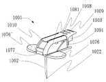
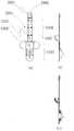
図1は、本発明である針組立体の第三の実施態様例であり、針組立体1001の使用後において、針先端収納した時の状態を示す斜視図である。図2は、本発明の針組立体についての図1の状態における縦断面図である。図2に示すように、針組立体1001は、略90°湾曲の湾曲部1021を有する針1002と、該針1002の基端部を保持するハブ1003とを有する。針組立体1001は、針1002の先端を保護する先端保護部1005を備え、先端保護部1005とハブ1003との間には、脚部である制限部1006を備え、生体の皮膚などに固定される固定部1007を備えている。針組立体1001においては、針1002を備えたハブ1003を覆うように、カバー部材1008が設けられている。カバー部材1008は、その上部に、関節として機能する接合部1010を介して、取っ手部1009を備えている。図1においては、略90°湾曲の湾曲部1021を有する針1002のハブ1003に繋がるように取っ手部1009を針組立体に設けているが、湾曲部が設けられていない一般針のハブに取っ手部を設けることができる。前記取っ手部をハブに設けることにより、前記針組立体の穿刺状態から針の引抜き状態とする際に取っ手部を引き上げることで、ハブが持ち上がる。このハブの持ち上がりによって、生体等から針が容易に引き抜くことができる。FIG.1 shows a third embodiment of the needle assembly according to the present invention, and is a perspective view showing a state when the needle tip is stored after the
前記固定部1007は、先端保護部1005とヒンジ部1077を介して繋がっている。前記針1002は、生体の設置された面に対して略水平になっているハブ1003に装着され、湾曲によって針先が下向きとなっている。図2の実施態様例においては、針1002として、刃面を穿刺方向に対して垂直とする形状のフーバー針を用いているが、その他の医療用の針を用いることもできる。前記湾曲部の湾曲は、図2においては略90°であるが、特に略90°の限定されるものではない。しかし、ハブ1003の両側面にある把持部1081を指で挟み持って下方へ押しつけるだけで、ポートや生体に針を刺すことが可能であり、しかも針管が設置面と水平方向に延びる部分を有する為に、針管の配置も容易であるので、湾曲部の湾曲が略90°であることが好ましい。The fixing
図1の実施態様例については、図2に示すように、使用後の状態において針1002の針先端部1022が先端保護部1005の内側に納められる。先端保護部1005は、制限部1006によって針先が収納された状態の位置よりも先端側に移動することができないようになっている。また、先端保護部1005は、内側部材1503と外側部材1502とからなり、図2に示すように針先囲繞構造を有している。先端保護部1005は、針先端部1022を取り囲み、制限部1006によって先端保護部1005と針先端部1022との位置関係が規制されるので、該針先囲繞構造を超えて先端保護部5の外部に針先端部1022が抜け出ることができない。なお、針1002は、針及び/または先端保護部の針接触部分の可撓性により、先端保護部1005の内側に針先端部1022が収納されることとなる。なお、ハブ1003のチューブ接続孔1034には、チューブ(図示せず)が挿入されて接続され、針1002の管腔とチューブ内腔とが連通することとなる。1 , as shown in FIG.2 , the
図1における実施態様例について、図3は、本発明の針組立体1001の使用前における状態を示す斜視図であり、図4は、図3の状態における本発明の針組立体1001の縦断面図である。使用前における針組立体1001は、図3の様に、制限部1006が折りたたまれた状態であって、ハブ1003と固定部1007とが、ハブ1003の係合部1032と固定部1007の接続部1071とで接続された状態である。図1に示すように、固定部1007は、接続部1071に係止部1072を備えており、係合部1032の係合突起1035と係止部1072とが係合して、ハブ1003と固定部1007とが接続されている。For the example embodiment in FIG.1, FIG.3 is a perspective view showing a state before use of the
また、図3において、針1002は、先端保護部1005の第一開口部1051から先端保護部1005を通り、第二開口部1052から抜け、さらに固定部1007の針通路1073を通って固定部1007より突き出た状態となっている。この使用前の状態において、例えば、針組立体1001を用いて薬液の注入を行う場合には、針組立体1001のカバー部材1008の両側面にある把持部1081を指で挟み持って針1002を生体組織に刺入して、チューブ接続孔1034に接続されたチューブ(図示せず)及び針1002の管腔を介して、生体等に薬液を注入することができる。なお、針組立体1001について、図3および図4の使用前の状態から、針先端が保護された図1及び図2の使用後の状態とするには、例えば、次のようにすることができる。図3の状態で針1002が生体やポートに刺入されている針組立体1001について、生体表面に設置さている固定部1007の翼部1076、1076’を一方の手の指で下方へ押さえつけて、もう一方の手の指で把持部1081を挟んで持ち上げることにより、固定部1007とハブ1003との係合が解除されて分離され、図1・図2の様な使用後の状態(針先が保護された状態)となる。なお、把持部1081は指で固定しやすいように、もしくは滑り止めとして、突起を設けてもよい。また、別の穿刺方法として翼部を折り曲げて翼部を介して把持部を挟んで穿刺しても良い。Further, in FIG.3, the
針組立体1001は、図3及び図4の使用状態においては、取っ手部1009に設けられた留め具1091の爪部1092が固定部1007に設けられた留め受け部1074の孔1075に挿入されて係合している。この係合により、取っ手部1009は図3に示すようにカバー部材に装着された状態でいる。使用後の状態において、穿刺された針組立体1001を生体等から引き抜くに際して、取っ手部1009は、先端部が引き上げられて係合が解除され、図1に示すように、持ち上がった状態とされる。取っ手部1009は、基端が接合部1010を介してカバー部材1008に取り付けられ、ハブ1003へと繋がっている。翼部1076、1076’を一方の手の指で下方へ押さえつけて、もう一方の手で取っ手部1009を持って、図1・図2の様に、鉛直方向に持ち上げることにより、ハブ1003及び針1002は持ち上がり、刺入された生体等から針1002が引き抜かれる。この針1002の引き抜きに際して、取っ手部の基端Xが、針1002の垂直部の略直上にあることが好ましい。取っ手部の基端が針1002の垂直部の略直上にあることにより、針基端部を覆って針を固定する本体部には、取っ手部の基端が起点となって、引き上げる力が加わり、針1002が先端若しくは基端方向に揺れることなく持ち上げることができる。針1002の垂直部よりも水平方向にやや先端側の上方に有ることが、針先端部を先端保護部へ収納することが容易であることから、より好ましい。なお、本実施態様例においては、ハブとカバー部材とにより針を支持する本体部が構成され、該カバー部材の上部に取っ手部が接合されているが、ハブへと繋がるように取っ手部が本体部に、又は針部に直接設けられていればよい。3 and4 , the
図1の実施態様例は、その構成が特に限定されるものではないが、例えば、下記の様な構成とすることができる。ハブは図5に示すように下側に一対の係合突起を備え、両側面にはそれぞれ一対の凸部1036、1036’を有している。ハブを覆うように取り付けられるカバー部材には、図6に示すように、両側面にそれぞれ一対の孔1082、1082’が設けられ、該孔は、カバー部材がハブに取り付けられた際に、前記凸部が前記孔に嵌合するようになっている。また、図7のように、固定部と先端保護部と制限部については、固定部と先端保護部と制限部とが連接された連接体2001が形成され、制限部の先端保護部が設けられた端部の他端には一対の突起2021が設けられた平板状の取付部2002が設けられている。前記取付部2002に設けられた突起2021がハブの同一側面に設けられた凸部1036、1036’との間の幅と同じ幅で設けられているので、前記針が先端保護部の第一開口部及び第二開口部を通った状態で、一対の前記突起をそれぞれ前記凸部間に嵌めるように、前記取付部をハブの上側に取り付ける。さらに前記取付部の上からカバー部材をハブに取り付けることにより、本発明の針組立体における第三の実施態様例は、容易に組立てることができる。なお、図1の実施態様例においては、固定部、先端保護部及び制限部が連続して一体的に設けられた連接体2001を用いているが、特に、これらの要素が一体となった連接体を用いることは、針先保護に関しては、本発明の必須の構成要素ではない。しかし、たとえば、図7に示すように、固定部、先端保護部、制限部、取付部の順に各部の間にそれぞれヒンジ部が設けられ連接体は、隣接する互いの部分に対して、任意の角度とすることができるので、針組立体の組立が容易でしかも、使用前の状態から使用後の状態への変形をスムースに行うことができるので、針先保護が容易であるので好ましい。なお、これらの嵌合は接着でも構わない。The configuration of the embodiment shown in FIG.1 is not particularly limited. For example, the configuration may be as follows. Hub has each have a pair of
図1の実施態様例においては、先端保護部は、二部材からなっており、外側部材1502と内側部材1503とを備えている。内側部材1503は、一方の側面に側方開口部1531を有している。針先囲繞構造を有する内側部材として用いることができる。該側方開口部1531は、右側面1534と底面との境界において第二開口端1533を有し、右側面1534と背面1535との境界において第一開口端1532を有している。図8の様に、該側方開口部1531は、針1002の湾曲部に対応した形状で、針1002の鉛直方向に延びている部分については第二開口端1533を通り、針1002の水平方向に延びている部分については第一開口端1532を通って、該湾曲部が該側方開口部を通って内側部材の内側に収納される形状とされている。前記先端保護部としては、このような先端保護部の内側部材の形状とすることにより、前記ハブの上部に連接体の取付部を取付け、ハブの係合突起を固定部の係合受部に係合させて、連接体と針とハブとで図3のような使用前状態とし、前記内側部材を前記外側部材の側面から嵌め入れて、ついでカバー部材を上からかぶせることで、針先を傷つけずしかも容易に針組立体を組立てることができる。In the embodiment example of FIG.1 , the tip protection part is composed of two members, and includes an
図1の実施態様例における制限部は、先端保護部とハブとの距離を制限する為の機能を十分に発揮することができて、先端保護部から針先が外部へ再露出することを抑制するものであれば特に限定されるものではない。なお、本発明において、制限部は、機能を発揮することができれば、一対の脚部として示されているが、はしご状であっても、板状であっても良い。Limiting unit in the example embodiment of FIG.1is able to sufficiently exhibit the function for limiting the distance between theprevious end protecting portion and the hub, that the needle tip from thetip protector portion is re-exposed to the outside If it suppresses, it will not specifically limit. In the present invention, the restricting portion is shown as a pair of leg portions as long as it can perform its function, but may be a ladder shape or a plate shape.
Claims (11)
Translated fromJapanese該針と該ハブとの距離を規制し、使用前の状態において折りたたまれた構造を形成する制限部と、
ヒンジ部を介して前記先端保護部に接続され、前記針が軸方向に移動できる針通路を有する固定部と、
前記ハブと繋がり、穿刺状態から前記針の引抜き状態とする際に、引き上げることによって接合部を介して前記ハブを持ち上げる取っ手部と、
を備え、
該先端保護部は、前記固定部に対し、前記ヒンジ部を介して回転するとともに、前記針の基端側に設けられた第一開口部と、前記針の先端側に設けられた第二開口部と、該第二開口部に設けられた針先戻り防止部とを含んで、針先が撓む機構を有し、
前記針は、弾性および湾曲部を有するフーバー針であって、
使用前の状態において、前記針が、前記先端保護部の第一開口部から先端保護部に入り、第二開口部から抜け出た状態であり、
使用後において、該先端保護部が該針の先端を保護する位置に移動した際に、前記機構により針先が撓んで、該針先が前記第二開口部から移動して該先端保護部の内側に針先が収納されることにより、該針の先端が保護されることを特徴とする針組立体。A needle assembly having a needle with a cutting edge formed at the tip, a hub for holding the proximal end of the needle, and a tip protector;
A restricting portion that regulates a distance between the needle and the hub andforms afolded structure in a state before use;
A fixing part connected to the tip protection part via a hinge part and having a needle passage through which the needle can move in the axial direction;
A handle portion that is connected to thehub and lifts the hub via a joint portion by pulling up when the needle is pulled out from a puncture state ,
With
The distal end protection partrotates with respect to the fixed part via the hinge part, and a first opening provided on the proximal end side of the needle and a second opening provided on the distal end side of the needle Including a portion and a needle tip return prevention portion provided in the second opening, and a mechanism for bendingthe needle tip,
The needle is a Hoover needle having elasticity and a curved portion,
In a state before use, the needle is in a state where it enters the tip protection part from the first opening of the tip protection part and comes out of the second opening.
After use, when the tip protector moves to a position that protects the tip of the needle, the needle tip is bent by the mechanism, the needle tipmoves from the second opening, and the tip protector A needle assembly, wherein the tip of the needle is protected by accommodating the needle tip inside.
前記取っ手部は、前記接合部を中心として先端部が弧を描く回動可能に設けられ、
前記取っ手部の端部を持ち上げることにより前記取っ手部と前記固定部との係合が解除されることを特徴とする請求項1〜4のいずれかに記載の針組立体。The handle portion has a fastener for the handle portion is connected to thesolid tough provided in the tip protector portion,
The handle portion is provided so as to be rotatable with a tip portion arcing around the joint portion,
The needle assembly according toany one of claims 1 to4, wherein the handle part and the fixing part are disengaged by lifting an end part of the handle part.
前記接合部は、前記針の水平方向において、前記針における湾曲部よりも先端側を構成する垂直部のほぼ直上となるような位置に設けられたことを特徴とする請求項1〜5のいずれかに記載の針組立体。The handle is connected to the hub via a joint,
The joint is in the horizontal direction of the needle,any of the precedingclaims, characterized in that provided substantially right above become such a position of the vertical portion constituting the distal end side than the bending portion of the needle needle assembly according toany.
該針と該ハブとの距離を規制し、使用前の状態において折りたたまれた構造を形成する制限部と、
ヒンジ部を介して前記先端保護部に接続され、前記針が軸方向に移動できる針通路を有する固定部と、
前記ハブと繋がり、穿刺状態から前記針の引抜き状態とする際に、引き上げることによって接合部を介して前記ハブを持ち上げる取っ手部と、
を備え、
該先端保護部は、前記固定部に対し、前記ヒンジ部を介して回転するとともに、前記針の基端側に設けられた第一開口部と、前記針の先端側に設けられた第二開口部と、該第二開口部に設けられた針先戻り防止部とを含んで、針先が撓む機構を有し、
前記針は、弾性および湾曲部を有するフーバー針であって、
使用前の状態において、前記針が、前記先端保護部の第一開口部から先端保護部に入り、第二開口部から抜け出た状態であり、
使用後において、該先端保護部が該針の先端を保護する位置に移動した際に、前記機構により針先が撓んで、該針先が前記第二開口部から移動して該先端保護部の内側に針先が収納されることにより、該針の先端が保護されることを特徴とする針先保護機構。A needle tip protection mechanism comprising a needle having a cutting edge formed at the tip, a hub for holding the proximal end of the needle, and a tip protector;
A restricting portion that regulates a distance between the needle and the hub andforms afolded structure in a state before use;
A fixing part connected to the tip protection part via a hinge part and having a needle passage through which the needle can move in the axial direction;
A handle portion that is connected to thehub and lifts the hub via a joint portion by pulling up when the needle is pulled out from a puncture state ,
With
The distal end protection partrotates with respect to the fixed part via the hinge part, and a first opening provided on the proximal end side of the needle and a second opening provided on the distal end side of the needle Including a portion and a needle tip return prevention portion provided in the second opening, and a mechanism for bendingthe needle tip,
The needle is a Hoover needle having elasticity and a curved portion,
In a state before use, the needle is in a state where it enters the tip protection part from the first opening of the tip protection part and comes out of the second opening.
After use, when the tip protector moves to a position that protects the tip of the needle, the needle tip is bent by the mechanism, the needle tipmoves from the second opening, and the tip protector A needle tip protection mechanism characterized in that the tip of the needle is protected by storing the needle tip inside.
Priority Applications (1)
| Application Number | Priority Date | Filing Date | Title |
|---|---|---|---|
| JP2008513312AJP4853516B2 (en) | 2006-04-28 | 2007-04-27 | Safety needle assembly |
Applications Claiming Priority (4)
| Application Number | Priority Date | Filing Date | Title |
|---|---|---|---|
| JP2006126889 | 2006-04-28 | ||
| JP2006126889 | 2006-04-28 | ||
| PCT/JP2007/059259WO2007126085A1 (en) | 2006-04-28 | 2007-04-27 | Safety needle assembly |
| JP2008513312AJP4853516B2 (en) | 2006-04-28 | 2007-04-27 | Safety needle assembly |
Related Child Applications (2)
| Application Number | Title | Priority Date | Filing Date |
|---|---|---|---|
| JP2011053640ADivisionJP5099240B2 (en) | 2006-04-28 | 2011-03-10 | Needle assembly and needle tip protection mechanism |
| JP2011235616ADivisionJP5365680B2 (en) | 2006-04-28 | 2011-10-27 | Safety needle assembly |
Publications (2)
| Publication Number | Publication Date |
|---|---|
| JPWO2007126085A1 JPWO2007126085A1 (en) | 2009-09-10 |
| JP4853516B2true JP4853516B2 (en) | 2012-01-11 |
Family
ID=38655605
Family Applications (3)
| Application Number | Title | Priority Date | Filing Date |
|---|---|---|---|
| JP2008513312AActiveJP4853516B2 (en) | 2006-04-28 | 2007-04-27 | Safety needle assembly |
| JP2011053640AExpired - Fee RelatedJP5099240B2 (en) | 2006-04-28 | 2011-03-10 | Needle assembly and needle tip protection mechanism |
| JP2011235616AActiveJP5365680B2 (en) | 2006-04-28 | 2011-10-27 | Safety needle assembly |
Family Applications After (2)
| Application Number | Title | Priority Date | Filing Date |
|---|---|---|---|
| JP2011053640AExpired - Fee RelatedJP5099240B2 (en) | 2006-04-28 | 2011-03-10 | Needle assembly and needle tip protection mechanism |
| JP2011235616AActiveJP5365680B2 (en) | 2006-04-28 | 2011-10-27 | Safety needle assembly |
Country Status (8)
| Country | Link |
|---|---|
| US (1) | US8496626B2 (en) |
| EP (1) | EP2016964B1 (en) |
| JP (3) | JP4853516B2 (en) |
| CN (1) | CN101432035B (en) |
| BR (1) | BRPI0710395B8 (en) |
| ES (1) | ES2899444T3 (en) |
| MX (1) | MX2008013742A (en) |
| WO (1) | WO2007126085A1 (en) |
Cited By (1)
| Publication number | Priority date | Publication date | Assignee | Title |
|---|---|---|---|---|
| JP2012016629A (en)* | 2006-04-28 | 2012-01-26 | Nipro Corp | Safety needle assembly |
Families Citing this family (36)
| Publication number | Priority date | Publication date | Assignee | Title |
|---|---|---|---|---|
| CA2599945C (en) | 2005-03-07 | 2011-07-12 | Erskine Medical Llc | Catheter introducer with needle shield |
| WO2010054990A1 (en)* | 2008-11-11 | 2010-05-20 | Novo Nordisk A/S | A bended injection needle |
| US20120123332A1 (en)* | 2009-03-05 | 2012-05-17 | Erskine Medical Llc | Needle-based medical device and related method |
| MX2012001403A (en) | 2009-07-31 | 2012-03-26 | Medical Components Inc | Huber needle with safety tube. |
| JP5538913B2 (en)* | 2010-01-13 | 2014-07-02 | 川澄化学工業株式会社 | Medical needle |
| EP2552522A4 (en)* | 2010-03-31 | 2014-06-11 | Autosafe Reflex Inc | Needle protective device |
| ES2725777T3 (en) | 2010-12-02 | 2019-09-27 | Erskine Medical Llc | Release mechanism for use with needle protection devices |
| MY161281A (en) | 2010-12-02 | 2017-04-14 | Erskine Medical Llc | Needle shield assembly with hub engagement member for needle device |
| WO2012139034A1 (en) | 2011-04-07 | 2012-10-11 | Erskine Medical Llc | Needle shielding device |
| EP2572742A1 (en)* | 2011-09-23 | 2013-03-27 | Sanofi-Aventis Deutschland GmbH | Needle safety device |
| WO2013098986A1 (en)* | 2011-12-28 | 2013-07-04 | 川澄化学工業株式会社 | Medical needle safety device |
| JP2013138853A (en)* | 2011-12-28 | 2013-07-18 | Kawasumi Lab Inc | Medical needle safety device |
| USD714931S1 (en)* | 2012-02-28 | 2014-10-07 | Repro-Med Systems, Inc. | Subcutaneous needle assembly |
| CN104334210B (en)* | 2012-03-07 | 2017-08-04 | 医疗部件有限公司 | huber needle assembly |
| DE102012102519A1 (en) | 2012-03-23 | 2013-09-26 | Pfm Medical Ag | Safety pin device, in particular for puncturing a subcutaneously implanted port in a human or animal body |
| WO2014049886A1 (en)* | 2012-09-28 | 2014-04-03 | テルモ株式会社 | Puncture device and medical fluid application device |
| US9119939B2 (en)* | 2013-09-12 | 2015-09-01 | Michael J. Botich | Rotatable hypodermic needle and method of use |
| JP6837839B2 (en) | 2013-09-18 | 2021-03-03 | アリアンス バスキュラー デバイス エルエルシーAlliance Vascular Devices Llc | Medical infusion device and its usage |
| US10549028B2 (en) | 2013-09-18 | 2020-02-04 | Alliance Vascular Devices, Llc | Medical infusion device and methods of use |
| MX370463B (en) | 2013-10-10 | 2019-12-13 | Medical Components Inc | Huber needle assembly with safety capture device. |
| USD787665S1 (en)* | 2013-11-28 | 2017-05-23 | Pengfei Wu | Curved hypodermic needle |
| EA034470B1 (en)* | 2014-03-28 | 2020-02-11 | Баксалта Инкорпорейтед | Subcutaneous infusion device for injecting medicinal substances |
| US10058651B1 (en)* | 2014-04-22 | 2018-08-28 | Suntori Medical, LLC | Safety needle device for accessing a medical port |
| MX2017002698A (en) | 2014-08-29 | 2017-05-23 | Medical Components Inc | Huber safety needle. |
| USD804021S1 (en) | 2015-02-27 | 2017-11-28 | Medical Components, Inc. | Huber safety needle |
| USD804022S1 (en) | 2015-02-27 | 2017-11-28 | Medical Components, Inc. | Huber safety needle |
| US11318254B2 (en)* | 2015-10-09 | 2022-05-03 | West Pharma. Services IL, Ltd. | Injector needle cap remover |
| AU2017234800B2 (en)* | 2016-03-18 | 2020-09-17 | Medical Components, Inc. | Huber safety needle |
| JP6941292B2 (en)* | 2017-07-24 | 2021-09-29 | ニプロ株式会社 | Needle assembly |
| CN108066846B (en)* | 2017-12-28 | 2021-02-12 | 罗亚琴 | Needle head protection device and needle head protection equipment |
| BR112020022218A2 (en) | 2018-05-01 | 2021-02-02 | Becton, Dickinson And Company | compression activated blood collection set |
| CN108888828A (en)* | 2018-07-13 | 2018-11-27 | 苏州林华医疗器械股份有限公司 | A kind of not damaged safty pin |
| BR112021012644A2 (en)* | 2018-12-27 | 2021-09-08 | Poly Medicure Limited | NEEDLES THAT HAVE A SAFETY MECHANISM |
| USD884160S1 (en)* | 2019-02-25 | 2020-05-12 | iMed Technology, Inc. | Huber safety needle |
| CN111686342A (en)* | 2020-07-02 | 2020-09-22 | 苏州林华医疗器械股份有限公司 | Needle-prick-proof and damage-free needle |
| CN117504049A (en)* | 2022-07-29 | 2024-02-06 | 普昂(杭州)医疗科技股份有限公司 | Safety needle assembly |
Citations (1)
| Publication number | Priority date | Publication date | Assignee | Title |
|---|---|---|---|---|
| US20050049553A1 (en)* | 2003-08-27 | 2005-03-03 | Triplett Daniel J. | Safety needle with positive flush |
Family Cites Families (12)
| Publication number | Priority date | Publication date | Assignee | Title |
|---|---|---|---|---|
| US5562637A (en)* | 1994-07-15 | 1996-10-08 | Utterberg; David S. | Needle protector sheath |
| US5681295A (en)* | 1996-07-03 | 1997-10-28 | Becton, Dickinson And Company | Needle shield assembly having a single-use cannula lock |
| US7198618B2 (en)* | 1999-11-04 | 2007-04-03 | Tyco Healthcare Group Lp | Safety shield for medical needles |
| US6537255B1 (en) | 2000-10-09 | 2003-03-25 | B Braun Medical, Inc. | Huber needle with folding safety wings |
| JP3740994B2 (en)* | 2001-03-30 | 2006-02-01 | 富士ゼロックス株式会社 | Color toner for electrophotography, color image forming method and color image forming apparatus |
| US6613015B2 (en)* | 2001-10-04 | 2003-09-02 | Deltec, Inc. | Right angle safety needle |
| US6755805B1 (en)* | 2002-09-13 | 2004-06-29 | Alan Reid | Needle device having enhanced safety |
| US7497845B2 (en)* | 2002-09-13 | 2009-03-03 | Alan Reid | Needle device having slideable member providing enhanced safety |
| US6969372B1 (en) | 2003-01-07 | 2005-11-29 | Halseth Thor R | Automatic retraction Huber needle safety enclosure |
| US6997902B2 (en)* | 2003-11-13 | 2006-02-14 | David L. Thorne | Safety shield for medical needles |
| CA2543083C (en) | 2003-11-13 | 2012-02-07 | Specialized Health Products, Inc. | Safety shield for medical needles |
| JP4853516B2 (en)* | 2006-04-28 | 2012-01-11 | ニプロ株式会社 | Safety needle assembly |
- 2007
- 2007-04-27JPJP2008513312Apatent/JP4853516B2/enactiveActive
- 2007-04-27CNCN2007800148505Apatent/CN101432035B/enactiveActive
- 2007-04-27MXMX2008013742Apatent/MX2008013742A/enactiveIP Right Grant
- 2007-04-27BRBRPI0710395Apatent/BRPI0710395B8/enactiveIP Right Grant
- 2007-04-27WOPCT/JP2007/059259patent/WO2007126085A1/enactiveApplication Filing
- 2007-04-27USUS12/225,830patent/US8496626B2/enactiveActive
- 2007-04-27ESES07742694Tpatent/ES2899444T3/enactiveActive
- 2007-04-27EPEP07742694.8Apatent/EP2016964B1/enactiveActive
- 2011
- 2011-03-10JPJP2011053640Apatent/JP5099240B2/ennot_activeExpired - Fee Related
- 2011-10-27JPJP2011235616Apatent/JP5365680B2/enactiveActive
Patent Citations (1)
| Publication number | Priority date | Publication date | Assignee | Title |
|---|---|---|---|---|
| US20050049553A1 (en)* | 2003-08-27 | 2005-03-03 | Triplett Daniel J. | Safety needle with positive flush |
Cited By (1)
| Publication number | Priority date | Publication date | Assignee | Title |
|---|---|---|---|---|
| JP2012016629A (en)* | 2006-04-28 | 2012-01-26 | Nipro Corp | Safety needle assembly |
Also Published As
| Publication number | Publication date |
|---|---|
| MX2008013742A (en) | 2008-11-14 |
| JP5365680B2 (en) | 2013-12-11 |
| EP2016964A4 (en) | 2014-06-11 |
| US20090163875A1 (en) | 2009-06-25 |
| CN101432035B (en) | 2013-01-30 |
| CN101432035A (en) | 2009-05-13 |
| EP2016964A1 (en) | 2009-01-21 |
| BRPI0710395B8 (en) | 2021-06-22 |
| BRPI0710395B1 (en) | 2018-11-13 |
| JP5099240B2 (en) | 2012-12-19 |
| JPWO2007126085A1 (en) | 2009-09-10 |
| WO2007126085A1 (en) | 2007-11-08 |
| BRPI0710395A2 (en) | 2015-05-05 |
| ES2899444T3 (en) | 2022-03-11 |
| JP2012016629A (en) | 2012-01-26 |
| EP2016964B1 (en) | 2021-10-06 |
| US8496626B2 (en) | 2013-07-30 |
| JP2011115615A (en) | 2011-06-16 |
Similar Documents
| Publication | Publication Date | Title |
|---|---|---|
| JP4853516B2 (en) | Safety needle assembly | |
| EP1256355B1 (en) | Combination needle assembly and needle safety guard | |
| ES2324560T3 (en) | SECURITY SCREEN. | |
| KR101323568B1 (en) | Non-axial return spring for safety needle | |
| KR101303268B1 (en) | Catheter and introducer needle assembly with safety device | |
| US7455664B2 (en) | Huber needle with anti-rebound safety mechanism | |
| JP4480338B2 (en) | Needle assembly | |
| KR20080060246A (en) | Safety needle with locking mechanism | |
| WO1996009083A1 (en) | A needle guard | |
| JP4973025B2 (en) | Safety needle assembly | |
| JP4319601B2 (en) | Curved needle with wings | |
| US8882727B2 (en) | Needle having a safety device | |
| ES2549776T3 (en) | Needle guard set | |
| WO1998057689A1 (en) | Shield for catheter introducer needles | |
| CA2892691A1 (en) | Transfusion needle with security | |
| JP4872362B2 (en) | Safety needle assembly having a curved portion | |
| US20040082922A1 (en) | Huber needle with anti-rebound safety mechanism | |
| JP3123296B2 (en) | Syringe assembly | |
| MXPA00002067A (en) | Medical needle safety apparatus and methods |
Legal Events
| Date | Code | Title | Description |
|---|---|---|---|
| A621 | Written request for application examination | Free format text:JAPANESE INTERMEDIATE CODE: A621 Effective date:20091126 | |
| A131 | Notification of reasons for refusal | Free format text:JAPANESE INTERMEDIATE CODE: A131 Effective date:20110118 | |
| TRDD | Decision of grant or rejection written | ||
| A01 | Written decision to grant a patent or to grant a registration (utility model) | Free format text:JAPANESE INTERMEDIATE CODE: A01 Effective date:20110927 | |
| A01 | Written decision to grant a patent or to grant a registration (utility model) | Free format text:JAPANESE INTERMEDIATE CODE: A01 | |
| A61 | First payment of annual fees (during grant procedure) | Free format text:JAPANESE INTERMEDIATE CODE: A61 Effective date:20111010 | |
| FPAY | Renewal fee payment (event date is renewal date of database) | Free format text:PAYMENT UNTIL: 20141104 Year of fee payment:3 | |
| R150 | Certificate of patent or registration of utility model | Ref document number:4853516 Country of ref document:JP Free format text:JAPANESE INTERMEDIATE CODE: R150 Free format text:JAPANESE INTERMEDIATE CODE: R150 | |
| R250 | Receipt of annual fees | Free format text:JAPANESE INTERMEDIATE CODE: R250 | |
| R250 | Receipt of annual fees | Free format text:JAPANESE INTERMEDIATE CODE: R250 | |
| R250 | Receipt of annual fees | Free format text:JAPANESE INTERMEDIATE CODE: R250 | |
| R250 | Receipt of annual fees | Free format text:JAPANESE INTERMEDIATE CODE: R250 |