JP4852091B2 - Gradient magnetic field coil apparatus, nuclear magnetic resonance imaging apparatus, and coil pattern design method - Google Patents
Gradient magnetic field coil apparatus, nuclear magnetic resonance imaging apparatus, and coil pattern design methodDownload PDFInfo
- Publication number
- JP4852091B2 JP4852091B2JP2008326130AJP2008326130AJP4852091B2JP 4852091 B2JP4852091 B2JP 4852091B2JP 2008326130 AJP2008326130 AJP 2008326130AJP 2008326130 AJP2008326130 AJP 2008326130AJP 4852091 B2JP4852091 B2JP 4852091B2
- Authority
- JP
- Japan
- Prior art keywords
- coil
- magnetic field
- gradient magnetic
- coil pattern
- line
- Prior art date
- Legal status (The legal status is an assumption and is not a legal conclusion. Google has not performed a legal analysis and makes no representation as to the accuracy of the status listed.)
- Active
Links
Images


Classifications
- G—PHYSICS
- G01—MEASURING; TESTING
- G01R—MEASURING ELECTRIC VARIABLES; MEASURING MAGNETIC VARIABLES
- G01R33/00—Arrangements or instruments for measuring magnetic variables
- G01R33/20—Arrangements or instruments for measuring magnetic variables involving magnetic resonance
- G01R33/28—Details of apparatus provided for in groups G01R33/44 - G01R33/64
- G01R33/38—Systems for generation, homogenisation or stabilisation of the main or gradient magnetic field
- G01R33/385—Systems for generation, homogenisation or stabilisation of the main or gradient magnetic field using gradient magnetic field coils
- A—HUMAN NECESSITIES
- A61—MEDICAL OR VETERINARY SCIENCE; HYGIENE
- A61B—DIAGNOSIS; SURGERY; IDENTIFICATION
- A61B5/00—Measuring for diagnostic purposes; Identification of persons
- A61B5/05—Detecting, measuring or recording for diagnosis by means of electric currents or magnetic fields; Measuring using microwaves or radio waves
- A61B5/055—Detecting, measuring or recording for diagnosis by means of electric currents or magnetic fields; Measuring using microwaves or radio waves involving electronic [EMR] or nuclear [NMR] magnetic resonance, e.g. magnetic resonance imaging
- G—PHYSICS
- G01—MEASURING; TESTING
- G01R—MEASURING ELECTRIC VARIABLES; MEASURING MAGNETIC VARIABLES
- G01R33/00—Arrangements or instruments for measuring magnetic variables
- G01R33/20—Arrangements or instruments for measuring magnetic variables involving magnetic resonance
- G01R33/28—Details of apparatus provided for in groups G01R33/44 - G01R33/64
- G01R33/38—Systems for generation, homogenisation or stabilisation of the main or gradient magnetic field
- G01R33/3806—Open magnet assemblies for improved access to the sample, e.g. C-type or U-type magnets
- G—PHYSICS
- G01—MEASURING; TESTING
- G01R—MEASURING ELECTRIC VARIABLES; MEASURING MAGNETIC VARIABLES
- G01R33/00—Arrangements or instruments for measuring magnetic variables
- G01R33/20—Arrangements or instruments for measuring magnetic variables involving magnetic resonance
- G01R33/28—Details of apparatus provided for in groups G01R33/44 - G01R33/64
- G01R33/38—Systems for generation, homogenisation or stabilisation of the main or gradient magnetic field
- G01R33/385—Systems for generation, homogenisation or stabilisation of the main or gradient magnetic field using gradient magnetic field coils
- G01R33/3854—Systems for generation, homogenisation or stabilisation of the main or gradient magnetic field using gradient magnetic field coils means for active and/or passive vibration damping or acoustical noise suppression in gradient magnet coil systems
Landscapes
- Physics & Mathematics (AREA)
- Health & Medical Sciences (AREA)
- Life Sciences & Earth Sciences (AREA)
- Condensed Matter Physics & Semiconductors (AREA)
- General Physics & Mathematics (AREA)
- Nuclear Medicine, Radiotherapy & Molecular Imaging (AREA)
- Engineering & Computer Science (AREA)
- Medical Informatics (AREA)
- Biophysics (AREA)
- Pathology (AREA)
- High Energy & Nuclear Physics (AREA)
- Biomedical Technology (AREA)
- Heart & Thoracic Surgery (AREA)
- Radiology & Medical Imaging (AREA)
- Molecular Biology (AREA)
- Surgery (AREA)
- Animal Behavior & Ethology (AREA)
- General Health & Medical Sciences (AREA)
- Public Health (AREA)
- Veterinary Medicine (AREA)
- Magnetic Resonance Imaging Apparatus (AREA)
Description
Translated fromJapanese本発明は、核磁気共鳴撮像(以下、MRIと称す)装置と、前記MRI装置に用いられる傾斜磁場コイル装置と、前記傾斜磁場コイル装置に備えられたコイルのコイルパターンの設計方法に関する。 The present invention relates to a nuclear magnetic resonance imaging (hereinafter referred to as MRI) apparatus, a gradient coil apparatus used in the MRI apparatus, and a method for designing a coil pattern of a coil provided in the gradient coil apparatus.
MRI装置は、均一な静磁場中に置かれた被検体に高周波パルスを照射したときに生じる核磁気共鳴現象を利用して、被検体の物理的、化学的性質を表す断面画像を得る装置であり、特に、医療用として用いられている。MRI装置は、主に、被検体が挿入される撮像領域に均一な静磁場を生成する静磁場コイル装置と、撮像領域に位置情報を付与するために空間的に磁場強度が傾斜勾配した傾斜磁場をパルス状に発生させる傾斜磁場コイル装置と、被検体に高周波パルスを照射するRFコイルと、被検体からの磁気共鳴信号を受信する受信コイルと、受信した磁気共鳴信号を処理して前記断面画像を表示するコンピュータシステムとを有している。 An MRI apparatus is a device that obtains a cross-sectional image representing the physical and chemical properties of a subject by utilizing a nuclear magnetic resonance phenomenon that occurs when a subject placed in a uniform static magnetic field is irradiated with a high-frequency pulse. In particular, it is used for medical purposes. The MRI apparatus mainly includes a static magnetic field coil device that generates a uniform static magnetic field in an imaging region into which a subject is inserted, and a gradient magnetic field in which the magnetic field strength is spatially inclined to give position information to the imaging region. , A gradient coil device for generating a pulse, an RF coil for irradiating a subject with a high frequency pulse, a receiving coil for receiving a magnetic resonance signal from the subject, and processing the received magnetic resonance signal to obtain the cross-sectional image And a computer system for displaying.
そして、MRI装置の性能向上のために、線形に磁場強度が傾斜勾配した傾斜磁場を発生させる傾斜磁場コイル装置が提案されている(特許文献1参照)。
従来の傾斜磁場コイル装置には、複雑なコイルパターンのコイルが設けられている。そのコイルパターンには、1つの面上に、複数の一箇所開いたループ形状の本線が、隣接する前記本線の内側になるように多重に配置され、隣接する前記本線間を接続する渡り線と、内側の前記本線から外側の前記本線の外側に引き出される戻り線とが、互いに、一部重なるように設けられている。 A conventional gradient magnetic field coil apparatus is provided with a coil having a complicated coil pattern. In the coil pattern, a plurality of loop-shaped main lines opened at one place on one surface are arranged in multiple so as to be inside the adjacent main lines, and connecting wires connecting the adjacent main lines; A return line drawn from the inner main line to the outer side of the outer main line is provided so as to partially overlap each other.
複数の本線を、一箇所開いたループ形状にして多重に配置し、隣接する前記本線間を渡り線で接続することで、多重の本線が連結した渦状のコイルパターンを形成している。そして、戻り線を設けることで、複数の本線に電流を流すことを可能にしている。しかし、従来の傾斜磁場コイル装置では、複数の本線にのみ電流が流れた場合に、線形の傾斜磁場が形成されるように設計されているので、電流が渡り線と戻り線に流れると、これにより誤差磁場が発生する。この誤差磁場は、静磁場コイル装置において渦電流を発生させ、この渦電流は断面画像を乱す磁場を撮像領域に形成する場合があった。 A plurality of main lines are formed in a loop shape opened at one place and arranged in a multiple manner, and the adjacent main lines are connected by a crossover line to form a spiral coil pattern in which the multiple main lines are connected. And by providing a return line, it is possible to flow current through a plurality of main lines. However, the conventional gradient coil apparatus is designed so that a linear gradient magnetic field is formed when current flows only on a plurality of main lines. Due to this, an error magnetic field is generated. This error magnetic field generates an eddy current in the static magnetic field coil device, and this eddy current may form a magnetic field that disturbs the cross-sectional image in the imaging region.
そこで、本発明の目的は、誤差磁場さらには渦電流の発生を抑制し、断面画像の画質を向上できる傾斜磁場コイル装置、MRI装置、および、コイルパターンの設計方法を提供することにある。 Accordingly, an object of the present invention is to provide a gradient magnetic field coil apparatus, an MRI apparatus, and a coil pattern design method capable of suppressing the generation of an error magnetic field and further an eddy current and improving the image quality of a cross-sectional image.
前記目的を達成するために、本発明は、MRI装置の撮像領域に線形な磁場分布を作る第1コイルと、前記第1コイルから前記撮像領域に均一な磁場分布を作る静磁場コイル装置への漏れ磁場を抑制する第2コイルとを備え、前記第1コイルと前記第2コイルの少なくともどちらか一方では、渦状のコイルパターンからの戻り線と交差する渡り線が前記コイルパターンとして谷と山を連ねたように下がって上がって又下がるように蛇行している傾斜磁場コイル装置であること、さらに、これを備えたMRI装置であることを特徴としている。In order to achieve the above object, the present invention provides a first coil that creates a linear magnetic field distribution in an imaging region of an MRI apparatus, and a static magnetic field coil device that creates a uniform magnetic field distribution from the first coil to the imaging region. and a second coil to suppress the leakage magnetic field,said at one least one of the first coil and the second coil,valleys and mountains connectingwire intersecting the return line from the coil pattern spiral isas the coil pattern The gradient magnetic field coil device is meanderingso as to go up and down as it is connected, and further, it is an MRI apparatus equipped with the same.
また、本発明では、前記コイルパターンへの給電線と前記戻り線とに交差する前記コイルパターンの一区間が凸形状に折り曲げられるように迂回していることが好ましい。In the presentinvention,it is preferable that a section of the coil pattern which intersects withthe return line and the feed line tothe coil pattern is divertedto be bent in a convex shape.
また、本発明は、MRI装置の撮像領域に線形な磁場分布を作る第1コイルと、前記第1コイルから前記撮像領域に均一な磁場分布を作る静磁場コイル装置への漏れ磁場を抑制する第2コイルの少なくともどちらか一方のコイルパターンの設計方法であって、予め用意された初期コイルパターンに基づいて、前記静磁場コイル装置へ入り込む誤差磁場を計算し、前記初期コイルパターンの渦状のコイルパターンからの戻り線と交差する渡り線上を流れ前記誤差磁場を打ち消す谷と山を連ねたような補正電流成分を計算し、前記補正電流成分に基づいて前記初期コイルパターンの前記渡り線を谷と山を連ねたように下がって上がって又下がり蛇行するように変形するコイルパターンの設計方法であることを特徴としている。さらに、このコイルパターンの設計方法を用いて設計され製造された前記第1コイルと前記第2コイルの少なくともどちらか一方を有する傾斜磁場コイル装置およびMRI装置であることを特徴としている。The present invention also provides a first coil that creates a linear magnetic field distribution in the imaging region of the MRI apparatus, and a first magnetic field that suppresses a leakage magnetic field from the first coil to the static magnetic field coil device that creates a uniform magnetic field distribution in the imaging region. A design method for a coil pattern of at least one of two coils, wherein an error magnetic field entering the static magnetic field coil device is calculated based on an initial coil pattern prepared in advance, and aspiral coil pattern of the initial coil patternA correction current component is calculated by connecting atrough and a mountainthat flow on the crossover line intersecting with the return line from the line and cancels the error magnetic field,and the crossover line of theinitial coil pattern isconverted into a trough and a peakbased on the correction current component. As described above, the coil pattern is designed to be deformed so as to go down and to meander down . Further, the magnetic field coil apparatus and the MRI apparatus have at least one of the first coil and the second coil designed and manufactured by using this coil pattern design method.
本発明によれば、誤差磁場さらには渦電流の発生を抑制し、断面画像の画質を向上できる傾斜磁場コイル装置、MRI装置、および、コイルパターンの設計方法を提供することができる。 According to the present invention, it is possible to provide a gradient magnetic field coil apparatus, an MRI apparatus, and a coil pattern design method capable of suppressing the generation of an error magnetic field and further an eddy current and improving the image quality of a cross-sectional image.
次に、本発明の実施形態について、適宜図面を参照しながら詳細に説明する。なお、各図において、共通する部分には同一の符号を付し重複した説明を省略する。 Next, embodiments of the present invention will be described in detail with reference to the drawings as appropriate. In each figure, common portions are denoted by the same reference numerals, and redundant description is omitted.
(第1の実施形態)
図1に、本発明の第1の実施形態に係るMRI(核磁気共鳴撮像)装置1の斜視図を示す。MRI装置1は静磁場7の向きが垂直方向である垂直磁場型MRI装置である。MRI装置1は、ベッド6に横たわった被検体5が挿入される撮像領域8に対して上下から挟むように配置され撮像領域8に均一な静磁場7を生成する上下一対の静磁場コイル装置2と、この上下一対の静磁場コイル装置2を離間して支持する連結柱17と、撮像領域8に位置情報を付与するために空間的に磁場強度が傾斜勾配した傾斜磁場をパルス状に発生させる傾斜磁場コイル装置3と、撮像領域8に挿入された被検体5に高周波パルスを照射するRFコイル4と、被検体5からの磁気共鳴信号を受信する受信コイル(図示省略)と、受信した磁気共鳴信号を処理して被検体5の断面画像を表示するコンピュータシステム(図示省略)とを有している。上下一対の静磁場コイル装置2と、傾斜磁場コイル装置3と、RFコイル4とは、対称軸10を共通の軸とする円板(円柱)形状をしている。被検体5は可動式のベッド6によって撮像領域8まで運ばれるが、上下一対の静磁場コイル装置2をつなぐのは細い連結柱17のみであるので、被検体5は周囲を見渡せ閉所感を軽減することができる。また、後記する説明の理解を容易にするために対称軸10と平行さらには一致する鉛直方向にz軸を設定し、水平方向で互いに直角になるようにx軸とy軸とを設定している。(First embodiment)
FIG. 1 shows a perspective view of an MRI (nuclear magnetic resonance imaging)
図2に、本発明の第1の実施形態に係るMRI装置1を対称軸10(z軸)を含むy−z平面で切断した断面図を示す。上下一対の静磁場コイル装置2には、上下一対の静磁場メインコイル2aと、上下一対の静磁場シールドコイル2bとが用いられている。上下一対の静磁場メインコイル2aと上下一対の静磁場シールドコイル2bはそれぞれ、前記対称軸10を共通の中心軸とする円環形状をしている。また、上下一対の静磁場メインコイル2aと上下一対の静磁場シールドコイル2bは、3層構造の容器内に収納されている。まず、一対の静磁場メインコイル2aと一対の静磁場シールドコイル2bは、冷媒の液体ヘリウム(He)と共に冷媒容器2e内に収容されている。冷媒容器2eは内部への熱輻射を遮断する熱輻射シールド2dに内包されている。そして、真空容器2cは、冷媒容器2e及び熱輻射シールド2dを収容しつつ、内部を真空に保持している。真空容器2cは、普通の室温の室内に配置されても、真空容器2c内が真空になっているので、室内の熱が伝導や対流で、冷媒容器2eに伝わることはない。また、熱輻射シールド2dは、室内の熱が輻射によって真空容器2cから冷媒容器2eに伝わることを抑制している。このため、一対の静磁場メインコイル2aと一対の静磁場シールドコイル2bは、冷媒の温度である極低温に安定して設定することができ、超伝導電磁石として機能させることができる。冷媒容器2eと、熱輻射シールド2dと、真空容器2cには、磁場による力が作用しないように非磁性の部材が用いられ、さらに、加工の容易性から非磁性の金属が用いられる。このため、冷媒容器2eと、熱輻射シールド2dと、真空容器2cには、電流、特に、渦電流が流れうる状況にある。 FIG. 2 shows a cross-sectional view of the
傾斜磁場コイル装置3も上下一対有し、上下一対の傾斜磁場コイル装置3は、撮像領域8を挟んで上下に配置されている。RFコイル4も上下一対有し、上下一対のRFコイル4は、撮像領域8を挟んで上下に配置されている。上下一対の上側の傾斜磁場コイル装置3は、上下一対の上側の静磁場コイル装置2と、上下一対の上側のRFコイル4の間で両者に近接して配置されている。同様に、上下一対の下側の傾斜磁場コイル装置3は、上下一対の下側の静磁場コイル装置2と、上下一対の下側のRFコイル4の間で両者に近接して配置されている。上下一対の傾斜磁場コイル装置3は、任意の方向に静磁場7と同じ方向の磁場強度が傾斜した傾斜磁場9をパルス状に発生させる。傾斜磁場コイル装置3は、x方向、y方向、z方向の3方向に独立な傾斜磁場9を、静磁場7に重ねて発生できるような機能を持っている。図2ではy方向に傾斜した傾斜磁場9を示している。 The gradient magnetic
図3に、上下一対の傾斜磁場コイル装置3の断面図を示す。傾斜磁場コイル装置3は、撮像領域8を挟んで上下に配置される上下一対の傾斜磁場コイルGCを有している。上下一対の傾斜磁場コイルGCは、撮像領域8を挟んで上下に配置される上下一対の傾斜磁場メインコイル(第1コイル)GMCと、撮像領域8を挟んで上下に配置される上下一対の傾斜磁場シールドコイル(第2コイル)GSCとを有している。上下一対の傾斜磁場シールドコイル(第2コイル)GSCの間に、上下一対で撮像領域8を挟ん状態の傾斜磁場メインコイルGMCが配置されている。上下一対の上側の傾斜磁場メインコイルGMCと、上下一対の上側の傾斜磁場シールドコイルGSCとは、支持部材3aを介して、互いに支持し合っている。同様に、上下一対の下側の傾斜磁場メインコイルGMCと、上下一対の下側の傾斜磁場シールドコイルGSCとは、支持部材3aを介して、互いに支持し合っている。そして、上下一対の上側の傾斜磁場コイル装置3、特に、上下一対の上側の傾斜磁場シールドコイルGSCは、上下一対の上側の静磁場コイル装置2、特に、上下一対の上側の真空容器2cに近接して配置されている。同様に、上下一対の下側の傾斜磁場コイル装置3、特に、上下一対の下側の傾斜磁場シールドコイルGSCは、上下一対の下側の静磁場コイル装置2、特に、上下一対の下側の真空容器2cに近接して配置されている。 FIG. 3 shows a cross-sectional view of a pair of upper and lower
上下一対の傾斜磁場メインコイルGMCは、x方向に線形に変化する傾斜磁場を作り撮像領域8を挟んで上下に配置される上下一対のx方向傾斜磁場メインコイルxGMCと、y方向に線形に変化する傾斜磁場を作り撮像領域8を挟んで上下に配置される上下一対のy方向傾斜磁場メインコイルyGMCと、z方向に線形に変化する傾斜磁場を作り撮像領域8を挟んで上下に配置される上下一対のz方向傾斜磁場メインコイルzGMCとを有している。x方向傾斜磁場メインコイルxGMCと、y方向傾斜磁場メインコイルyGMCと、z方向傾斜磁場メインコイルzGMCとは、それぞれが、1対の傾斜磁場コイル装置3毎に層(3層)をなし、この3層の傾斜磁場メインコイルxGMC、yGMC、zGMCが1対となり、対毎にこの3層がz方向に支持部材3aの絶縁層を挟んで積層されている。 The pair of upper and lower gradient magnetic field main coils GMC creates a gradient magnetic field that linearly changes in the x direction, and linearly changes in the y direction with a pair of upper and lower x direction gradient magnetic field main coils xGMC that are arranged above and below the
上下一対の傾斜磁場シールドコイルGSCは、x方向傾斜磁場メインコイルxGMCの形成する磁場が周囲に漏れるのを抑制し撮像領域8を挟んで上下に配置される上下一対のx方向傾斜磁場シールドコイルxGSCと、y方向傾斜磁場メインコイルyGMCの形成する磁場が周囲に漏れるのを抑制し撮像領域8を挟んで上下に配置される上下一対のy方向傾斜磁場シールドコイルyGSCと、z方向傾斜磁場メインコイルzGMCの形成する磁場が周囲に漏れるのを抑制し撮像領域8を挟んで上下に配置される上下一対のz方向傾斜磁場シールドコイルzGSCとを有している。x方向傾斜磁場シールドコイルxGSCと、y方向傾斜磁場シールドコイルyGSCと、z方向傾斜磁場シールドコイルzGSCとは、それぞれが、1対の傾斜磁場コイル装置3毎に層(3層)をなし、この3層の傾斜磁場シールドコイルxGSC、yGSC、zGSCが1対となり、対毎にこの3層がz方向に支持部材3aの絶縁層を挟んで積層されている。 The pair of upper and lower gradient magnetic field shield coils GSC suppresses the magnetic field formed by the x-direction gradient magnetic field main coil xGMC from leaking to the surroundings, and a pair of upper and lower x-direction gradient magnetic field shield coils xGSC are arranged above and below the imaging region 8 A pair of upper and lower y-direction gradient magnetic field shield coils yGSC which are arranged above and below the
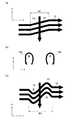
図4(a)に、y方向傾斜磁場メインコイルyGMCと、y方向傾斜磁場シールドコイルyGSCの配置図を示す。y方向傾斜磁場メインコイルyGMCは、z軸を中心軸とする2つ円板形状の層(図示省略)に、2つずつ計4つ配置されている。4つのy方向傾斜磁場メインコイルyGMCはそれぞれ、略半円形で渦巻状の扇型コイルであるが、渦巻きの形状の図示は省略し大まかな電流の方向のみを示している。4つのy方向傾斜磁場メインコイルyGMCは、2つずつに、x軸−y軸平面で分けられるとともにその平面に面対称の構造をしている。また、4つのy方向傾斜磁場メインコイルyGMCは、2つずつに、z軸−x軸平面で分けられるとともにその平面に面対称の構造をしている。なお、矢印は、コイルに流れる電流の向きを示しており、後記も同様である。 FIG. 4A shows a layout of the y-direction gradient magnetic field main coil yGMC and the y-direction gradient magnetic field shield coil yGSC. A total of four y-direction gradient magnetic field main coils yGMC are arranged in two disk-shaped layers (not shown) each having a z-axis as a central axis. Each of the four y-direction gradient magnetic field main coils yGMC is a substantially semicircular and spiral fan-shaped coil. However, the spiral shape is not shown, and only a rough current direction is shown. The four y-direction gradient magnetic field main coils yGMC are divided into two in the x-axis-y-axis plane and have a plane-symmetric structure on the plane. The four y-direction gradient magnetic field main coils yGMC are divided into z-axis and x-axis planes two by two and have a plane-symmetric structure on the planes. The arrow indicates the direction of the current flowing through the coil, and the same applies to the following.
y方向傾斜磁場シールドコイルyGSCは、z軸を中心軸とする2つの円板形状の層(図示省略)に、2つずつ計4つ配置されている。4つのy方向傾斜磁場シールドコイルyGSCはそれぞれ、略半円形で渦巻状の扇型コイルであり、対応するy方向傾斜磁場メインコイルyGMCを覆うように配置されている。なお、渦巻きの形状の図示は省略し大まかな電流の方向のみを示している。4つのy方向傾斜磁場シールドコイルyGSCは、2つずつに、x軸−y軸平面で分けられるとともにその平面に面対称の構造をしている。また、4つのy方向傾斜磁場シールドコイルyGSCは、2つずつに、z軸−x軸平面で分けられるとともにその平面に面対称の構造をしている。 A total of four y-direction gradient magnetic field shield coils yGSC are arranged in two disk-shaped layers (not shown) having the z-axis as the central axis. Each of the four y-direction gradient magnetic field shield coils yGSC is a substantially semicircular and spiral fan coil, and is disposed so as to cover the corresponding y-direction gradient magnetic field main coil yGMC. In addition, illustration of the shape of a spiral is abbreviate | omitted and only the direction of the rough electric current is shown. The four y-direction gradient magnetic field shield coils yGSC are divided by two on the x-axis-y-axis plane and have a plane-symmetric structure on the plane. The four y-direction gradient magnetic field shield coils yGSC are divided into two z-axis-x-axis planes and have a plane-symmetric structure on each plane.
図4(b)に、x方向傾斜磁場メインコイルxGMCと、x方向傾斜磁場シールドコイルxGSCの配置図を示す。x方向傾斜磁場メインコイルxGMCは、z軸を中心軸とする2つの円板形状の層(図示省略)に、2つずつ計4つ配置されている。4つのx方向傾斜磁場メインコイルxGMCはそれぞれ、略半円形で渦巻状の扇型コイルであるが、渦巻きの形状の図示は省略し大まかな電流の方向のみを示している。4つのx方向傾斜磁場メインコイルxGMCは、2つずつに、x軸−y軸平面で分けられるとともにその平面に面対称の構造をしている。また、4つのx方向傾斜磁場メインコイルxGMCは、2つずつに、y軸−z軸平面で分けられるとともにその平面に面対称の構造をしている。 FIG. 4B shows a layout of the x-direction gradient magnetic field main coil xGMC and the x-direction gradient magnetic field shield coil xGSC. A total of four x-direction gradient magnetic field main coils xGMC are arranged in two disk-shaped layers (not shown) each having a z-axis as a central axis. Each of the four x-direction gradient magnetic field main coils xGMC is a substantially semicircular and spiral fan-shaped coil, but the spiral shape is not shown, and only a rough current direction is shown. Each of the four x-direction gradient magnetic field main coils xGMC is divided into two planes on the x-axis-y-axis plane and has a plane-symmetric structure on the plane. In addition, the four x-direction gradient magnetic field main coils xGMC are divided by two on the y-axis-z-axis plane and have a plane-symmetric structure on the plane.
x方向傾斜磁場シールドコイルxGSCは、z軸を中心軸とする2つの円板形状の層(図示省略)に、2つずつ計4つ配置されている。4つのx方向傾斜磁場シールドコイルxGSCはそれぞれ、略半円形で渦巻状の扇型コイルであり、対応するx方向傾斜磁場メインコイルxGMCを覆うように配置されている。なお、渦巻きの形状の図示は省略し大まかな電流の方向のみを示している。4つのx方向傾斜磁場シールドコイルxGSCは、2つずつに、x軸−y軸平面で分けられるとともにその平面に面対称の構造をしている。また、4つのx方向傾斜磁場シールドコイルxGSCは、2つずつに、y軸−z軸平面で分けられとともにその平面に面対称の構造をしている。 A total of four x-direction gradient magnetic field shield coils xGSC are arranged in two disk-shaped layers (not shown) each having a z-axis as a central axis. Each of the four x-direction gradient magnetic field shield coils xGSC is a substantially semicircular and spiral fan-shaped coil, and is disposed so as to cover the corresponding x-direction gradient magnetic field main coil xGMC. In addition, illustration of the shape of a spiral is abbreviate | omitted and only the direction of the rough electric current is shown. The four x-direction gradient magnetic field shield coils xGSC are divided by two on the x-axis-y-axis plane and have a plane-symmetric structure on the plane. The four x-direction gradient magnetic field shield coils xGSC are divided by two on the y-axis-z axis plane and have a plane-symmetric structure on the plane.
図4(c)に、z方向傾斜磁場メインコイルzGMCと、z方向傾斜磁場シールドコイルzGSCの配置図を示す。z方向傾斜磁場メインコイルzGMCは、z軸を中心軸とする2つの円板形状の層(図示省略)に、1つずつ計2つ配置されている。2つのz方向傾斜磁場メインコイルzGMCは、円形状で渦巻状の円型コイルであるが、渦巻の図示は省略し大まかな電流の方向のみを示している。2つのz方向傾斜磁場メインコイルzGMCは、1つずつに、x軸−y軸平面で分けられるとともにその平面に面対称の構造をしている。 FIG. 4C shows a layout of the z-direction gradient magnetic field main coil zGMC and the z-direction gradient magnetic field shield coil zGSC. A total of two z-direction gradient magnetic field main coils zGMC are arranged one by one on two disk-shaped layers (not shown) having the z-axis as a central axis. The two z-direction gradient magnetic field main coils zGMC are circular and spiral circular coils, but the spiral is not shown and only the direction of a rough current is shown. The two z-direction gradient magnetic field main coils zGMC are divided one by one on the x-axis-y-axis plane and have a plane-symmetric structure on the plane.
z方向傾斜磁場シールドコイルzGSCは、z軸を中心軸とする2つの円板形状の層(図示省略)に、1つずつ計2つ配置されている。2つのz方向傾斜磁場シールドコイルzGSCは、円形状で渦巻状の円型コイルであり、対応するz方向傾斜磁場メインコイルzGMCを覆うように配置されている。なお、渦巻の図示は省略し大まかな電流の方向のみを示している。2つのz方向傾斜磁場シールドコイルzGSCは、1つずつに、x軸−y軸平面で分けられるとともにその平面に面対称の構造をしている。 A total of two z-direction gradient magnetic field shield coils zGSC are arranged on two disk-shaped layers (not shown) each having a z-axis as a central axis. The two z-direction gradient magnetic field shield coils zGSC are circular and spiral circular coils, and are arranged so as to cover the corresponding z-direction gradient magnetic field main coil zGMC. In addition, illustration of a spiral is abbreviate | omitted and only the direction of the rough electric current is shown. The two z-direction gradient magnetic field shield coils zGSC are divided one by one on the x-axis-y-axis plane and have a plane-symmetric structure on the plane.
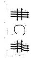
図5(a)に、y方向傾斜磁場シールドコイルyGSCのパターン図を示す。また、図5(b)は図5(a)のA−A方向の断面図であり、図5(c)は図5(a)のB−B方向の断面図である。y方向傾斜磁場シールドコイルyGSCのコイルパターンに対して、y方向傾斜磁場メインコイルyGMCは、少し大きさの小さい相似形のコイルパターンとなる。x方向傾斜磁場シールドコイルxGSCは、y方向傾斜磁場シールドコイルyGSCのコイルパターンを90度回転しただけの合同形のコイルパターンになる。y方向傾斜磁場メインコイルyGMCは、y方向傾斜磁場シールドコイルyGSCのコイルパターンを90度回転して少し大きさの小さい相似形のコイルパターンになる。 FIG. 5A shows a pattern diagram of the y-direction gradient magnetic field shield coil yGSC. 5B is a cross-sectional view in the AA direction in FIG. 5A, and FIG. 5C is a cross-sectional view in the BB direction in FIG. 5A. The y-direction gradient magnetic field main coil yGMC has a slightly smaller size than the coil pattern of the y-direction gradient magnetic field shield coil yGSC. The x-direction gradient magnetic field shield coil xGSC is a congruent coil pattern obtained by rotating the coil pattern of the y-direction gradient magnetic field shield coil yGSC by 90 degrees. The y-direction gradient magnetic field main coil yGMC rotates the coil pattern of the y-direction gradient magnetic field shield coil yGSC by 90 degrees to become a similar coil pattern with a small size.
図5(a)に示すように、y方向傾斜磁場シールドコイルyGSCは、1平面(コイル面)上に複数本の本線12を有している。複数本の本線12は、複数(図5(a)では3つずつ)の領域に分かれて配置されている。第1の領域では、本線12は、隣接する本線12の内側になるように4重(多重)に配置されている。第2の領域では、本線12は、隣接する本線12の内側になるように2重(多重)に配置されている。第3の領域では、本線12は、1重に配置されている。そして、各領域の本線12に給電する給電線11と、給電線11に沿って配置され給電線11で給電された本線12から電流を戻す戻り線13とが設けられている。給電線11と戻り線13が本線12を跨ぐ箇所を、本線12における補正区間15とし、この補正区間15では、本線12が前記コイル面上で凸形状に折り曲げられることで迂回している。これによれば、給電線11と戻り線13によって誤差磁場が発生しても、給電線11と戻り線13の近傍の補正区間15において凸形状に折り曲げられることで迂回した本線12によって発生する磁場によって、誤差磁場をキャンセルできるので、静磁場コイル装置2の真空容器2c等に生じる渦電流を抑制でき、断面画像の画質を向上できる。なお、補正区間15の幅W2は、給電線11と戻り線13の間隔より大きく設定されている。 As shown in FIG. 5A, the y-direction gradient magnetic field shield coil yGSC has a plurality of
第1の領域や、第2の領域で、2重や4重の多重に配置されている複数本の本線12は、それぞれ、U文字形状のような一箇所開いたループ形状をしている。このループ形状(U文字形状)内の開いた箇所は、一列に並べられ、この箇所において、渡り線14は、隣接する本線12間を接続している。この接続により、多重の本線12が連結した渦状のコイルパターンを構成している。なお、この箇所の幅、すなわち、後記する渡り線14が設置される幅(渡り幅)W1は、戻り線13の配線の線幅より広く設定されている。渡り線14は、戻り線13となす90度以下の角度が、隣接する本線12間を直線で結んだ場合の戻り線13となす90度以下の角度より小さくなるように蛇行している。戻り線13は、前記領域間を接続するだけでなく、多重に配置された内側の本線12から外側の本線12の外側に配線を引き出すためにも接続され、渡り線13に重なるように配置されている。これによれば、戻り線13によって誤差磁場が発生しても、戻り線13の近傍の大きな傾きを持った渡り線14によって発生する磁場によって、誤差磁場をキャンセルできるので、静磁場コイル装置2の真空容器2c等に生じる渦電流を抑制でき、断面画像の画質を向上できる。 A plurality of
図5(b)に示すように、戻り線13は、渡り線14と静磁場コイル装置2の真空容器2cの間に配置されている。すなわち、真空容器2cに対して、戻り線13の方が、渡り線14より近い位置に配置されている。真空容器2cの近くにある戻り線13によって真空容器2cに生じる誤差磁場の強度は大きくなりやすく、この大きな誤差磁場をキャンセルするために、真空容器2cから遠い渡り線14によって真空容器2cに大きな磁場を発生させるべく、渡り線14を、戻り線13となす90度以下の角度が、隣接する本線12間を直線で結んだ場合の戻り線13となす90度以下の角度より小さくなるように蛇行させている。 As shown in FIG. 5B, the
図5(c)に示すように、給電線11と戻り線13とは、本線12の補正区間15と、静磁場コイル装置2の真空容器2cの間に配置されている。すなわち、真空容器2cに対して、給電線11と戻り線13の方が、本線12の補正区間15より近い位置に配置されている。真空容器2cの近くにある給電線11と戻り線13によって真空容器2cに生じる誤差磁場の強度は大きくなりやすく、この大きな誤差磁場をキャンセルするために、真空容器2cから遠い本線12の補正区間15では、応じて真空容器2cに大きな磁場を発生させるべく、補正区間15での凸形状に折り曲げる程度を加減することになる。 As shown in FIG. 5C, the
図6に、本発明の第1の実施形態に係る傾斜磁場コイル装置3のy方向傾斜磁場シールドコイルyGSC等のコイルパターンの設計方法のフローチャートを示す。 FIG. 6 shows a flowchart of a method for designing a coil pattern such as the y-direction gradient magnetic field shield coil yGSC of the gradient magnetic
まず、ステップS1で、y方向傾斜磁場シールドコイルyGSC等の、特に、本線12の形状(配置位置を含む)を計算し、図7(a)に示すように、渡り線14を直線形状として本線12に配線(接続)し、初期GCコイルパターンを決定する。 First, in step S1, the shape of the main line 12 (including the arrangement position), such as the y-direction gradient magnetic field shield coil yGSC, is calculated, and as shown in FIG. 12 is connected (connected) to determine an initial GC coil pattern.
ステップS2で、初期GCコイルパターンを形成しているコイル面20を、図8に示すように、3角メッシュの有限要素で分割し、3角メッシュの有限要素で生成した傾斜磁場コイル補正電流計算モデルを作成する。なお、図8は参考のために示す図であり、実際の計算に用いる場合より大きな三角要素を描いている。 In step S2, the
ステップS3で、ステップS1で用意された初期GCコイルパターンに基づいて、静磁場コイル装置2等における誤差磁場を計算する。誤差磁場は、図7(b)に示すような、静磁場コイル装置2の真空容器2c等の導体面を貫通するような磁力線16を発生させるので、図10に示すように真空容器2c等の導体面に入る磁場の方向と大きさ(強度)19の分布を算出することで、誤差磁場を計算することができる。 In step S3, an error magnetic field in the static magnetic
ステップS4で、誤差磁場を打ち消す補正電流成分を、コイル面上に存在するように計算する。これにより、図9(a)に示すような初期GCコイルパターンの戻り線13と渡り線14に対して、渡り線14の存在するコイル面上に存在する、図9(b)に示すような補正電流成分18a、18bを算出することができる。 In step S4, a correction current component that cancels the error magnetic field is calculated so as to exist on the coil surface. As a result, as shown in FIG. 9B, the coil exists on the coil surface where the
より具体的には、まず、有限面要素の接点に電流ポテンシャルを与え、その電流ポテンシャルを要素に持つ電流ポテンシャル分布を示すベクトルTにより表現される電流が、導体面上の誤差磁場Bを打ち消すように電流ポテンシャル分布Tを決める。電流ポテンシャルの勾配と電流(コイル)面の法線のベクトル積で電流密度ベクトルが表現される。そして、この近似的な解法に特異値分解を応用する手法を利用することで、複雑でなく、また渦電流の発生を抑え磁場の精度を改善することができる打消電流成分の電流ポテンシャルTを求めることができる。 More specifically, first, a current potential is applied to a contact of a finite surface element, and a current expressed by a vector T indicating a current potential distribution having the current potential as an element cancels the error magnetic field B on the conductor surface. A current potential distribution T is determined. The current density vector is expressed by the vector product of the gradient of the current potential and the normal of the current (coil) surface. Then, by using a technique that applies singular value decomposition to this approximate solution, a current potential T of a cancellation current component that is not complicated and that can suppress the generation of eddy currents and improve the accuracy of the magnetic field is obtained. be able to.
この方法で打消電流成分に対応する電流ポテンシャル分布Tが決まれば、次に導体(コイル)位置の変位分を計算する。導体間の距離dと導体の電流Icから、Ic/dは電流ポテンシャルの勾配と等価である。従って、補正電流成分の電流ポテンシャルTはT/(勾配)で導体位置の変位に換算できる。また、初期GCコイルパターンが電流ポテンシャル計算値T0を元に決まっていれば、導体(コイル)位置の変位分は、式T/▽T0で計算できる。 If the current potential distribution T corresponding to the cancellation current component is determined by this method, the displacement of the conductor (coil) position is then calculated. From the distance d between conductors and the conductor current Ic, Ic / d is equivalent to the gradient of the current potential. Therefore, the current potential T of the correction current component can be converted into the displacement of the conductor position by T / (gradient). If the initial GC coil pattern is determined based on the current potential calculation value T0, the displacement of the conductor (coil) position can be calculated by the equation T / TT0.
なお、補正電流成分の計算には、後記の文献で報告されている手法を用いることができる。その文献は、M. ABE, T. NAKAYAMA, S. OKAMURA, K. MATSUOKA , “A new technique to optimize coil winding path for the arbitrarily distributed magnetic field and application to a helical confinement system”, Phys. Plasmas. Vol.10 No.4 (2003)1022.である。 In addition, the method reported by the postscript can be used for calculation of a correction | amendment electric current component. The literature is M. ABE, T. NAKAYAMA, S. OKAMURA, K. MATSUOKA, “A new technique to optimize coil winding path for the arbitrarily distributed magnetic field and application to a helical confinement system”, Phys. Plasmas. Vol. 10 No.4 (2003) 1022.
ステップS5で、補正電流成分に基づいて初期GCコイルパターンを変形する。補正電流成分を初期GCコイルパターンに沿う電流成分に追加し、変形された電流成分を、図5(a)に示すようにy方向傾斜磁場シールドコイルyGSCのコイルパターンとして、修正GCコイルパターンを完成させることができる。具体的には、図9(a)に示す渡り線14に沿う電流成分に対して、図9(b)に示す補正電流成分18a、18bを追加・合成し、図9(c)に示すように戻り線13となす90度以下の角度が、隣接する本線12間を直線で結んだ場合の戻り線13となす90度以下の角度より小さくなるように蛇行した渡り線14に変更している。 In step S5, the initial GC coil pattern is deformed based on the correction current component. The corrected current component is added to the current component along the initial GC coil pattern, and the modified current component is used as the coil pattern of the y-direction gradient magnetic field shield coil yGSC as shown in FIG. Can be made. Specifically, correction
図11に、初期GCコイルパターンの渡り線14aと、修正GCコイルパターンの渡り線14とを重ねて示している。これより、渡り線14は、戻り線13と重なっている領域において、戻り線13となす90度以下の角度が、隣接する本線12間を直線で結んだ場合(14a)の戻り線13となす90度以下の角度より小さくなるように蛇行している。なお、初期GCコイルパターンと修正GCコイルパターンの渡り線14と本線12として、電流重心の流れを表示している。修正前後で電流(コイル)パターンは、図11の中央の戻り線13の図下側では、磁気モーメントが小さくなるように補正(渡り線14と渡り線14aで囲む面積が小さく補正)され、上側では磁気モーメントが大きくなるように補正されている。 In FIG. 11, the connecting
前記では、導体幅から、また元になる電流ポテンシャル計算結果から、電流ポテンシャルの勾配を求め、補正電流成分に相当する導体(コイル)位置の変位量を計算する方法を述べたが、これに限らず、図11に関連して述べたように、磁気モーメントを考えて補正する方法もある。電流ポテンシャルの面積積分値が磁気モーメントであるので、この積分をコイル面の1ターンもしくは数ターンを代表する領域毎に行い、該当のターンが囲む領域の面積と電流積が、変更すべき磁気モーメントの大きさになるように導体(コイル)位置の変位量の大きさを決めていく。いずれの補正方法でも効果は同じであり、修正GCコイルパターンは近接導電面の渦電流発生を極小とするコイルパターンとなる。 In the above, the method of obtaining the gradient of the current potential from the conductor width and from the original current potential calculation result and calculating the displacement amount of the conductor (coil) position corresponding to the correction current component has been described. First, as described with reference to FIG. 11, there is a method for correcting the magnetic moment. Since the integral value of the area of the current potential is the magnetic moment, this integration is performed for each region that represents one or several turns of the coil surface, and the area and current product of the region surrounded by the corresponding turn change the magnetic moment to be changed. The amount of displacement of the conductor (coil) position is determined so that the size becomes. The effect is the same in either correction method, and the modified GC coil pattern is a coil pattern that minimizes the generation of eddy currents on the adjacent conductive surface.
次に、図12を用いて、渡り線14が無くて、給電線11と戻り線13が往復電流を流しているところを、本線12が横切っている場合の、本線12の修正例について説明する。コイルパターンの設計方法のフローチャートに沿って説明すると、ステップS2までは、前記と同様に実施することができる。 Next, with reference to FIG. 12, a description will be given of a modification example of the
ステップS3で、ステップS1で用意された初期GCコイルパターンに基づいて、静磁場コイル装置2等における誤差磁場を計算する。初期GCコイルパターンでは、図12(a)に示すように、給電線11と戻り線13が往復電流を流しているところを、本線12が横切っている。 In step S3, an error magnetic field in the static magnetic
ステップS4で、誤差磁場を打ち消す補正電流成分を、コイル面上に存在するように計算する。これにより、図12(a)に示すような初期GCコイルパターンの給電線11と戻り線13と本線12に対して、本線12の存在するコイル面上に、図12(b)に示すような補正電流成分21を算出することができる。 In step S4, a correction current component that cancels the error magnetic field is calculated so as to exist on the coil surface. As a result, as shown in FIG. 12B, on the coil surface where the
ステップS5で、図12(a)に示す本線12に対して、図12(b)に示す補正電流成分21を追加・合成し、図12(c)に示すように補正区間15において凸形状に折り曲げられることで迂回する本線12に変更している。このような修正GCコイルパターンによっても、渦電流を発生させる誤差磁場を小さくすることができる。 In step S5, the correction
このように、第1の実施形態によれば、傾斜磁場コイルの設計において、真空容器2c等の近接導電面を貫く誤差磁場を弱くでき、渦電流の発生を抑制できるので、鮮明な診断画像を提供できる。また渦電流の発生を抑えることで、渦電流によって発生する振動も軽減できる。 Thus, according to the first embodiment, in the design of the gradient magnetic field coil, the error magnetic field penetrating through the adjacent conductive surface such as the
(第2の実施形態)
図13(a)に、本発明の第2の実施形態に係る傾斜磁場コイル装置のy方向傾斜磁場シールドコイル等の戻り線13と渡り線14の周辺のパターン図を示し、図13(b)にその周辺の戻り線13と渡り線14の断面図を示す。第2の実施形態が、第1の実施形態と異なる点は、図13(b)に示すように、戻り線13が、渡り線14を挟んで真空容器2c等の反対側に配置されている点である。これにより、真空容器2c等に対して、戻り線13の方が、渡り線14より遠い位置に配置されている。真空容器2cの遠くにある戻り線13によって真空容器2cに生じる誤差磁場の強度は小さく、この小さな誤差磁場をキャンセルするために、真空容器2cから近い渡り線14によって真空容器2cに応じた小さな磁場を発生させればよいので、渡り線14を、戻り線13となす90度以下の角度が、隣接する本線12間を直線で結んだ場合の戻り線13となす90度以下の角度より小さくなるように蛇行させる必要は無い。そして、第2の実施形態では、小さな誤差磁場をキャンセルするために、隣接する本線12間を直線状の渡り線14で接続し、渡り幅W3を可変にすることで、渡り線14の傾きを調整している。(Second Embodiment)
FIG. 13A shows a pattern diagram around the
図14に、第1の実施形態で説明したコイルパターンの設計方法を、第2の実施形態でも同様に実施した結果を示す。図14の(a)〜(d)は、戻り線13と渡り線14によって発生する真空容器(導体物)2c上の誤差磁場の方向と大きさの分布図であり、図14(a)は戻り線13の幅W4に対する渡り幅W3の比が4倍の場合であり、図14(b)は幅W4に対する渡り幅W3の比が6倍の場合であり、図14(c)は幅W4に対する渡り幅W3の比が8倍の場合であり、図14(d)は幅W4に対する渡り幅W3の比が10倍の場合である。誤差磁場のz方向の大きさが、真空容器(導体物)2c上の全領域にわたって小さい程、渦電流は発生し難いと考えられる。誤差磁場のz方向の大きさが全領域にわたって最も小さくなるのは、比が8倍前後の場合であり、その比より大きくなる程誤差磁場のz方向の大きさは大きくなり、その比より小さくなる程誤差磁場のz方向の大きさは大きくなった。そこで、比が4倍以上10倍以下であれば、概ね誤差磁場のz方向の大きさは全領域にわたって小さく抑えられることがわかった。これによれば、渦電流の発生も抑制できるので、断面画像の画質を向上することができる。 FIG. 14 shows the results of the coil pattern design method described in the first embodiment, which is similarly performed in the second embodiment. 14A to 14D are distribution diagrams of the direction and magnitude of the error magnetic field on the vacuum vessel (conductor) 2c generated by the
1 磁気共鳴イメージング(MRI)装置
2 静磁場コイル装置
2a 静磁場コイル(静磁場メインコイル)
2b 静磁場コイル(静磁場シールドコイル)
2c 容器(真空容器、導体物)
2d 熱輻射シールド
2e 冷媒容器
3 傾斜磁場コイル装置
4 RFコイル
5 被検体(患者)
6 ベッド
7 静磁場の向き
8 撮像領域(中央領域)
9 傾斜磁場
10 対称軸
11 給電線
12 本線
13 戻り線
14 渡り線
15 補正線
16 磁力線
17 連結柱
18a、18b 補正電流
19 磁場の方向と大きさ
20 コイル面
21 補正電流
GMC 傾斜磁場メインコイル
xGMC x方向傾斜磁場メインコイル
yGMC y方向傾斜磁場メインコイル
zGMC z方向傾斜磁場メインコイル
GSC 傾斜磁場シールドコイル
xGSC x方向傾斜磁場シールドコイル
yGSC y方向傾斜磁場シールドコイル
zGSC z方向傾斜磁場シールドコイル
W1、W3 渡り幅
W2 戻り線幅DESCRIPTION OF
2b Static magnetic field coil (static magnetic field shield coil)
2c Container (vacuum container, conductor)
2d
6
DESCRIPTION OF SYMBOLS 9 Gradient
Claims (9)
Translated fromJapanese前記第1コイルから前記撮像領域に均一な磁場分布を作る静磁場コイル装置への漏れ磁場を抑制する第2コイルとを備え、
前記第1コイルと前記第2コイルの少なくともどちらか一方では、渦状のコイルパターンからの戻り線と交差する渡り線が前記コイルパターンとして谷と山を連ねたように下がって上がって又下がるように蛇行していることを特徴とする傾斜磁場コイル装置。A first coil that creates a linear magnetic field distribution in the imaging region of the nuclear magnetic resonance imaging apparatus;
A second coil that suppresses a leakage magnetic field from the first coil to the static magnetic field coil device that creates a uniform magnetic field distribution in the imaging region;
Wherein while at least one of the first coil and the second coil,so connectingwire intersecting the return line from the coil pattern spiraldrops or up down as had been valleys and mountains as the coil pattern A gradient coil device characterized by meandering.
前記傾斜磁場コイル装置に近接して配置され、前記撮像領域に均一な静磁場を生成する静磁場コイル装置とを備えたことを特徴とする核磁気共鳴撮像装置。The gradient magnetic field coil device according toclaim 1or 2 ,
A nuclear magnetic resonance imaging apparatus comprising: a static magnetic field coil apparatus that is disposed in proximity to the gradient magnetic field coil apparatus and generates a uniform static magnetic field in the imaging region.
予め用意された初期コイルパターンに基づいて、前記静磁場コイル装置における誤差磁場を計算し、
前記初期コイルパターンの渦状のコイルパターンからの戻り線と交差する渡り線上を流れ前記誤差磁場を打ち消す谷と山を連ねたような補正電流成分を計算し、
前記補正電流成分に基づいて前記初期コイルパターンの前記渡り線を谷と山を連ねたように下がって上がって又下がり蛇行するように変形することを特徴とするコイルパターンの設計方法。A first coil that creates a linear magnetic field distribution in the imaging region of the nuclear magnetic resonance imaging apparatus, and a second coil that suppresses the leakage magnetic field from the first coil to the static magnetic field coil device that creates a uniform magnetic field distribution in the imaging region. A method for designing at least one of the coil patterns,
Based on the initial coil pattern prepared in advance, the error magnetic field in the static magnetic field coil device is calculated,
Calculatea correction current componentsuch as connecting a valley and a mountain thatflow on the crossing line intersecting the return line from the spiral coil pattern of the initial coil pattern and cancel the error magnetic field,
A method of designing a coil pattern, wherein the crossover wire of the initial coil patternis deformedso as to go up and down and meander down based on the correction current component.
前記初期コイルパターンと同一面上の電流ポテンシャル分布を計算することを特徴とする請求項5に記載のコイルパターンの設計方法。In calculating the correction current component,
6. The method of designing a coil pattern according to claim 5, wherein a current potential distribution on the same plane as the initial coil pattern is calculated.
前記第1コイルから前記撮像領域に均一な磁場分布を作る静磁場コイル装置への漏れ磁場を抑制する第2コイルとを備え、
前記第1コイルと前記第2コイルの少なくともどちらか一方では、渦状のコイルパターンからの戻り線と交差する渡り線が前記渡り線の両端の間で前記両端を結ぶ線分と交差するように蛇行していることを特徴とする傾斜磁場コイル装置。A first coil that creates a linear magnetic field distribution in the imaging region of the nuclear magnetic resonance imaging apparatus;
A second coil that suppresses a leakage magnetic field from the first coil to the static magnetic field coil device that creates a uniform magnetic field distribution in the imaging region;
At least one of the first coil and the second coil meandersso that the crossover that intersects the return line from the spiral coil pattern intersects thelinesegment that connects the both ends between the ends of the crossover A gradient magnetic field coil device characterized in that:
Priority Applications (2)
| Application Number | Priority Date | Filing Date | Title |
|---|---|---|---|
| JP2008326130AJP4852091B2 (en) | 2008-12-22 | 2008-12-22 | Gradient magnetic field coil apparatus, nuclear magnetic resonance imaging apparatus, and coil pattern design method |
| US12/644,470US8633698B2 (en) | 2008-12-22 | 2009-12-22 | Gradient coil device, magnetic resonance imaging device, and method of designing coil pattern |
Applications Claiming Priority (1)
| Application Number | Priority Date | Filing Date | Title |
|---|---|---|---|
| JP2008326130AJP4852091B2 (en) | 2008-12-22 | 2008-12-22 | Gradient magnetic field coil apparatus, nuclear magnetic resonance imaging apparatus, and coil pattern design method |
Related Child Applications (2)
| Application Number | Title | Priority Date | Filing Date |
|---|---|---|---|
| JP2011183283ADivisionJP5199426B2 (en) | 2011-08-25 | 2011-08-25 | Gradient magnetic field coil apparatus, nuclear magnetic resonance imaging apparatus, and coil pattern design method |
| JP2011183358ADivisionJP5373014B2 (en) | 2011-08-25 | 2011-08-25 | Gradient magnetic field coil apparatus, nuclear magnetic resonance imaging apparatus, and coil pattern design method |
Publications (2)
| Publication Number | Publication Date |
|---|---|
| JP2010142586A JP2010142586A (en) | 2010-07-01 |
| JP4852091B2true JP4852091B2 (en) | 2012-01-11 |
Family
ID=42397164
Family Applications (1)
| Application Number | Title | Priority Date | Filing Date |
|---|---|---|---|
| JP2008326130AActiveJP4852091B2 (en) | 2008-12-22 | 2008-12-22 | Gradient magnetic field coil apparatus, nuclear magnetic resonance imaging apparatus, and coil pattern design method |
Country Status (2)
| Country | Link |
|---|---|
| US (1) | US8633698B2 (en) |
| JP (1) | JP4852091B2 (en) |
Cited By (1)
| Publication number | Priority date | Publication date | Assignee | Title |
|---|---|---|---|---|
| JP2011240164A (en)* | 2011-08-25 | 2011-12-01 | Hitachi Medical Corp | Gradient magnetic field coil device, nuclear magnetic resonance imaging device, and coil pattern design method |
Families Citing this family (6)
| Publication number | Priority date | Publication date | Assignee | Title |
|---|---|---|---|---|
| CN102665543B (en)* | 2009-11-27 | 2015-08-26 | 株式会社日立医疗器械 | The method for designing of gradient magnetic field coil, NMR imaging equipment and coil pattern |
| WO2014003126A1 (en) | 2012-06-27 | 2014-01-03 | 株式会社 日立メディコ | Gradient magnetic field coil device and magnetic resonance imaging device |
| JP6138600B2 (en)* | 2013-06-12 | 2017-05-31 | ジャパンスーパーコンダクタテクノロジー株式会社 | Magnetic field generator |
| BR112017004353A2 (en) | 2014-09-05 | 2017-12-05 | Hyperfine Res Inc | ferromagnetic magnification for magnetic resonance imaging |
| EP3564694A1 (en) | 2018-04-30 | 2019-11-06 | Koninklijke Philips N.V. | Gradient shield coil with meandering winding for a magnetic resonance imaging apparatus |
| JP7606353B2 (en)* | 2021-01-21 | 2024-12-25 | キヤノンメディカルシステムズ株式会社 | Magnetic resonance imaging equipment |
Family Cites Families (11)
| Publication number | Priority date | Publication date | Assignee | Title |
|---|---|---|---|---|
| FR2588997B1 (en)* | 1985-10-18 | 1987-11-20 | Thomson Cgr | PROCESS FOR PRODUCING A GRADIENT COIL AND COIL OBTAINED BY THIS PROCESS |
| JP2708661B2 (en) | 1992-04-30 | 1998-02-04 | 三菱電機株式会社 | Gradient magnetic field generator |
| JP3299308B2 (en)* | 1992-07-02 | 2002-07-08 | ジーイー横河メディカルシステム株式会社 | Gradient magnetic field coil unit, gradient magnetic field coil and MRI apparatus |
| JPH07194574A (en)* | 1993-12-29 | 1995-08-01 | Toshiba Corp | Magnetic resonance diagnostic device |
| DE4422781C1 (en)* | 1994-06-29 | 1996-02-01 | Siemens Ag | Actively screened planar gradient coil for pole plate magnets |
| US6144204A (en)* | 1997-11-28 | 2000-11-07 | Picker Nordstar Oy | Gradient coils for magnetic resonance meeting |
| JP3283242B2 (en)* | 1999-06-21 | 2002-05-20 | ジーイー横河メディカルシステム株式会社 | Gradient coil manufacturing method, gradient coil and MRI apparatus |
| JP2001353137A (en)* | 2001-03-27 | 2001-12-25 | Ge Yokogawa Medical Systems Ltd | Method for manufacturing gradient magnetic field coil |
| FR2888670B1 (en)* | 2005-07-18 | 2009-11-20 | Centre Nat Rech Scient | AUTOMATIC COAXIAL IMPEDANCE ADAPTER |
| JP5308017B2 (en) | 2007-12-17 | 2013-10-09 | 八千代工業株式会社 | Steel plate cleaning equipment |
| US7932722B2 (en)* | 2009-04-27 | 2011-04-26 | General Electric Company | Transversely folded gradient coil |
- 2008
- 2008-12-22JPJP2008326130Apatent/JP4852091B2/enactiveActive
- 2009
- 2009-12-22USUS12/644,470patent/US8633698B2/enactiveActive
Cited By (1)
| Publication number | Priority date | Publication date | Assignee | Title |
|---|---|---|---|---|
| JP2011240164A (en)* | 2011-08-25 | 2011-12-01 | Hitachi Medical Corp | Gradient magnetic field coil device, nuclear magnetic resonance imaging device, and coil pattern design method |
Also Published As
| Publication number | Publication date |
|---|---|
| US8633698B2 (en) | 2014-01-21 |
| JP2010142586A (en) | 2010-07-01 |
| US20100194393A1 (en) | 2010-08-05 |
Similar Documents
| Publication | Publication Date | Title |
|---|---|---|
| JP5695241B2 (en) | Gradient magnetic field coil and nuclear magnetic resonance imaging apparatus | |
| JP4852091B2 (en) | Gradient magnetic field coil apparatus, nuclear magnetic resonance imaging apparatus, and coil pattern design method | |
| JP5352092B2 (en) | Gradient magnetic field coil apparatus and magnetic resonance imaging apparatus | |
| US7932722B2 (en) | Transversely folded gradient coil | |
| CN102481116B (en) | Gradient magnetic field coil and magnetic resonance imaging device | |
| JP5199426B2 (en) | Gradient magnetic field coil apparatus, nuclear magnetic resonance imaging apparatus, and coil pattern design method | |
| US7427908B1 (en) | Magnetic shimming configuration with optimized turn geometry and electrical circuitry | |
| JP5373014B2 (en) | Gradient magnetic field coil apparatus, nuclear magnetic resonance imaging apparatus, and coil pattern design method | |
| JP5204813B2 (en) | Gradient magnetic field coil and magnetic resonance imaging apparatus | |
| JP5202491B2 (en) | Magnetic resonance imaging system | |
| JP6039896B2 (en) | Electromagnet device and shim coil manufacturing method | |
| JP5848824B2 (en) | Gradient magnetic field coil apparatus and magnetic resonance imaging apparatus | |
| JP5819215B2 (en) | Gradient magnetic field coil and magnetic resonance imaging apparatus | |
| JP5128369B2 (en) | Magnetic resonance imaging system | |
| JP2010263955A (en) | Gradient coil unit | |
| JP4852053B2 (en) | Magnetic resonance imaging system | |
| JP2010284184A (en) | Magnetic resonance imaging apparatus | |
| JP5901561B2 (en) | Magnetic resonance imaging system | |
| JP2012016524A (en) | Magnetic resonance imaging apparatus |
Legal Events
| Date | Code | Title | Description |
|---|---|---|---|
| A621 | Written request for application examination | Free format text:JAPANESE INTERMEDIATE CODE: A621 Effective date:20101126 | |
| A131 | Notification of reasons for refusal | Free format text:JAPANESE INTERMEDIATE CODE: A131 Effective date:20110125 | |
| A02 | Decision of refusal | Free format text:JAPANESE INTERMEDIATE CODE: A02 Effective date:20110705 | |
| AA91 | Notification that invitation to amend document was cancelled | Free format text:JAPANESE INTERMEDIATE CODE: A971091 Effective date:20110802 | |
| A521 | Request for written amendment filed | Free format text:JAPANESE INTERMEDIATE CODE: A523 Effective date:20110825 | |
| TRDD | Decision of grant or rejection written | ||
| A01 | Written decision to grant a patent or to grant a registration (utility model) | Free format text:JAPANESE INTERMEDIATE CODE: A01 Effective date:20111004 | |
| A01 | Written decision to grant a patent or to grant a registration (utility model) | Free format text:JAPANESE INTERMEDIATE CODE: A01 | |
| A61 | First payment of annual fees (during grant procedure) | Free format text:JAPANESE INTERMEDIATE CODE: A61 Effective date:20111021 | |
| R150 | Certificate of patent or registration of utility model | Ref document number:4852091 Country of ref document:JP Free format text:JAPANESE INTERMEDIATE CODE: R150 Free format text:JAPANESE INTERMEDIATE CODE: R150 | |
| FPAY | Renewal fee payment (event date is renewal date of database) | Free format text:PAYMENT UNTIL: 20141028 Year of fee payment:3 | |
| S111 | Request for change of ownership or part of ownership | Free format text:JAPANESE INTERMEDIATE CODE: R313111 | |
| S533 | Written request for registration of change of name | Free format text:JAPANESE INTERMEDIATE CODE: R313533 | |
| R350 | Written notification of registration of transfer | Free format text:JAPANESE INTERMEDIATE CODE: R350 | |
| R250 | Receipt of annual fees | Free format text:JAPANESE INTERMEDIATE CODE: R250 | |
| S111 | Request for change of ownership or part of ownership | Free format text:JAPANESE INTERMEDIATE CODE: R313111 | |
| R350 | Written notification of registration of transfer | Free format text:JAPANESE INTERMEDIATE CODE: R350 | |
| R250 | Receipt of annual fees | Free format text:JAPANESE INTERMEDIATE CODE: R250 | |
| R250 | Receipt of annual fees | Free format text:JAPANESE INTERMEDIATE CODE: R250 | |
| S111 | Request for change of ownership or part of ownership | Free format text:JAPANESE INTERMEDIATE CODE: R313111 | |
| R350 | Written notification of registration of transfer | Free format text:JAPANESE INTERMEDIATE CODE: R350 | |
| R250 | Receipt of annual fees | Free format text:JAPANESE INTERMEDIATE CODE: R250 | |
| R250 | Receipt of annual fees | Free format text:JAPANESE INTERMEDIATE CODE: R250 |