JP4851091B2 - Graphite product used for gas diffusion layer for PEM fuel cell, method for forming the graphite product, and base material used for gas diffusion layer for PEM fuel cell - Google Patents
Graphite product used for gas diffusion layer for PEM fuel cell, method for forming the graphite product, and base material used for gas diffusion layer for PEM fuel cellDownload PDFInfo
- Publication number
- JP4851091B2 JP4851091B2JP2004541781AJP2004541781AJP4851091B2JP 4851091 B2JP4851091 B2JP 4851091B2JP 2004541781 AJP2004541781 AJP 2004541781AJP 2004541781 AJP2004541781 AJP 2004541781AJP 4851091 B2JP4851091 B2JP 4851091B2
- Authority
- JP
- Japan
- Prior art keywords
- sheet
- groove
- graphite
- expanded graphite
- graphite particles
- Prior art date
- Legal status (The legal status is an assumption and is not a legal conclusion. Google has not performed a legal analysis and makes no representation as to the accuracy of the status listed.)
- Expired - Fee Related
Links
Images


Classifications
- H—ELECTRICITY
- H01—ELECTRIC ELEMENTS
- H01M—PROCESSES OR MEANS, e.g. BATTERIES, FOR THE DIRECT CONVERSION OF CHEMICAL ENERGY INTO ELECTRICAL ENERGY
- H01M8/00—Fuel cells; Manufacture thereof
- H01M8/02—Details
- H01M8/0202—Collectors; Separators, e.g. bipolar separators; Interconnectors
- H01M8/023—Porous and characterised by the material
- H01M8/0234—Carbonaceous material
- H—ELECTRICITY
- H01—ELECTRIC ELEMENTS
- H01M—PROCESSES OR MEANS, e.g. BATTERIES, FOR THE DIRECT CONVERSION OF CHEMICAL ENERGY INTO ELECTRICAL ENERGY
- H01M4/00—Electrodes
- H01M4/86—Inert electrodes with catalytic activity, e.g. for fuel cells
- H01M4/96—Carbon-based electrodes
- H—ELECTRICITY
- H01—ELECTRIC ELEMENTS
- H01M—PROCESSES OR MEANS, e.g. BATTERIES, FOR THE DIRECT CONVERSION OF CHEMICAL ENERGY INTO ELECTRICAL ENERGY
- H01M4/00—Electrodes
- H01M4/86—Inert electrodes with catalytic activity, e.g. for fuel cells
- H01M4/8605—Porous electrodes
- H—ELECTRICITY
- H01—ELECTRIC ELEMENTS
- H01M—PROCESSES OR MEANS, e.g. BATTERIES, FOR THE DIRECT CONVERSION OF CHEMICAL ENERGY INTO ELECTRICAL ENERGY
- H01M4/00—Electrodes
- H01M4/86—Inert electrodes with catalytic activity, e.g. for fuel cells
- H01M4/88—Processes of manufacture
- H01M4/8803—Supports for the deposition of the catalytic active composition
- H01M4/881—Electrolytic membranes
- H—ELECTRICITY
- H01—ELECTRIC ELEMENTS
- H01M—PROCESSES OR MEANS, e.g. BATTERIES, FOR THE DIRECT CONVERSION OF CHEMICAL ENERGY INTO ELECTRICAL ENERGY
- H01M4/00—Electrodes
- H01M4/86—Inert electrodes with catalytic activity, e.g. for fuel cells
- H01M4/94—Non-porous diffusion electrodes, e.g. palladium membranes, ion exchange membranes
- H—ELECTRICITY
- H01—ELECTRIC ELEMENTS
- H01M—PROCESSES OR MEANS, e.g. BATTERIES, FOR THE DIRECT CONVERSION OF CHEMICAL ENERGY INTO ELECTRICAL ENERGY
- H01M8/00—Fuel cells; Manufacture thereof
- H01M8/02—Details
- H—ELECTRICITY
- H01—ELECTRIC ELEMENTS
- H01M—PROCESSES OR MEANS, e.g. BATTERIES, FOR THE DIRECT CONVERSION OF CHEMICAL ENERGY INTO ELECTRICAL ENERGY
- H01M8/00—Fuel cells; Manufacture thereof
- H01M8/02—Details
- H01M8/0202—Collectors; Separators, e.g. bipolar separators; Interconnectors
- H01M8/023—Porous and characterised by the material
- H01M8/0241—Composites
- H01M8/0245—Composites in the form of layered or coated products
- H—ELECTRICITY
- H01—ELECTRIC ELEMENTS
- H01M—PROCESSES OR MEANS, e.g. BATTERIES, FOR THE DIRECT CONVERSION OF CHEMICAL ENERGY INTO ELECTRICAL ENERGY
- H01M8/00—Fuel cells; Manufacture thereof
- H01M8/02—Details
- H01M8/0202—Collectors; Separators, e.g. bipolar separators; Interconnectors
- H01M8/0247—Collectors; Separators, e.g. bipolar separators; Interconnectors characterised by the form
- H—ELECTRICITY
- H01—ELECTRIC ELEMENTS
- H01M—PROCESSES OR MEANS, e.g. BATTERIES, FOR THE DIRECT CONVERSION OF CHEMICAL ENERGY INTO ELECTRICAL ENERGY
- H01M8/00—Fuel cells; Manufacture thereof
- H01M8/02—Details
- H01M8/0202—Collectors; Separators, e.g. bipolar separators; Interconnectors
- H01M8/0258—Collectors; Separators, e.g. bipolar separators; Interconnectors characterised by the configuration of channels, e.g. by the flow field of the reactant or coolant
- H01M8/026—Collectors; Separators, e.g. bipolar separators; Interconnectors characterised by the configuration of channels, e.g. by the flow field of the reactant or coolant characterised by grooves, e.g. their pitch or depth
- H—ELECTRICITY
- H01—ELECTRIC ELEMENTS
- H01M—PROCESSES OR MEANS, e.g. BATTERIES, FOR THE DIRECT CONVERSION OF CHEMICAL ENERGY INTO ELECTRICAL ENERGY
- H01M8/00—Fuel cells; Manufacture thereof
- H01M8/02—Details
- H01M8/0202—Collectors; Separators, e.g. bipolar separators; Interconnectors
- H01M8/0258—Collectors; Separators, e.g. bipolar separators; Interconnectors characterised by the configuration of channels, e.g. by the flow field of the reactant or coolant
- H01M8/0263—Collectors; Separators, e.g. bipolar separators; Interconnectors characterised by the configuration of channels, e.g. by the flow field of the reactant or coolant having meandering or serpentine paths
- H—ELECTRICITY
- H01—ELECTRIC ELEMENTS
- H01M—PROCESSES OR MEANS, e.g. BATTERIES, FOR THE DIRECT CONVERSION OF CHEMICAL ENERGY INTO ELECTRICAL ENERGY
- H01M8/00—Fuel cells; Manufacture thereof
- H01M8/04—Auxiliary arrangements, e.g. for control of pressure or for circulation of fluids
- H01M8/04007—Auxiliary arrangements, e.g. for control of pressure or for circulation of fluids related to heat exchange
- H01M8/04067—Heat exchange or temperature measuring elements, thermal insulation, e.g. heat pipes, heat pumps, fins
- H01M8/04074—Heat exchange unit structures specially adapted for fuel cell
- H—ELECTRICITY
- H01—ELECTRIC ELEMENTS
- H01M—PROCESSES OR MEANS, e.g. BATTERIES, FOR THE DIRECT CONVERSION OF CHEMICAL ENERGY INTO ELECTRICAL ENERGY
- H01M8/00—Fuel cells; Manufacture thereof
- H01M8/10—Fuel cells with solid electrolytes
- H01M8/1004—Fuel cells with solid electrolytes characterised by membrane-electrode assemblies [MEA]
- H—ELECTRICITY
- H01—ELECTRIC ELEMENTS
- H01M—PROCESSES OR MEANS, e.g. BATTERIES, FOR THE DIRECT CONVERSION OF CHEMICAL ENERGY INTO ELECTRICAL ENERGY
- H01M8/00—Fuel cells; Manufacture thereof
- H01M8/10—Fuel cells with solid electrolytes
- H01M2008/1095—Fuel cells with polymeric electrolytes
- Y—GENERAL TAGGING OF NEW TECHNOLOGICAL DEVELOPMENTS; GENERAL TAGGING OF CROSS-SECTIONAL TECHNOLOGIES SPANNING OVER SEVERAL SECTIONS OF THE IPC; TECHNICAL SUBJECTS COVERED BY FORMER USPC CROSS-REFERENCE ART COLLECTIONS [XRACs] AND DIGESTS
- Y02—TECHNOLOGIES OR APPLICATIONS FOR MITIGATION OR ADAPTATION AGAINST CLIMATE CHANGE
- Y02E—REDUCTION OF GREENHOUSE GAS [GHG] EMISSIONS, RELATED TO ENERGY GENERATION, TRANSMISSION OR DISTRIBUTION
- Y02E60/00—Enabling technologies; Technologies with a potential or indirect contribution to GHG emissions mitigation
- Y02E60/30—Hydrogen technology
- Y02E60/50—Fuel cells
- Y—GENERAL TAGGING OF NEW TECHNOLOGICAL DEVELOPMENTS; GENERAL TAGGING OF CROSS-SECTIONAL TECHNOLOGIES SPANNING OVER SEVERAL SECTIONS OF THE IPC; TECHNICAL SUBJECTS COVERED BY FORMER USPC CROSS-REFERENCE ART COLLECTIONS [XRACs] AND DIGESTS
- Y02—TECHNOLOGIES OR APPLICATIONS FOR MITIGATION OR ADAPTATION AGAINST CLIMATE CHANGE
- Y02P—CLIMATE CHANGE MITIGATION TECHNOLOGIES IN THE PRODUCTION OR PROCESSING OF GOODS
- Y02P70/00—Climate change mitigation technologies in the production process for final industrial or consumer products
- Y02P70/50—Manufacturing or production processes characterised by the final manufactured product
- Y—GENERAL TAGGING OF NEW TECHNOLOGICAL DEVELOPMENTS; GENERAL TAGGING OF CROSS-SECTIONAL TECHNOLOGIES SPANNING OVER SEVERAL SECTIONS OF THE IPC; TECHNICAL SUBJECTS COVERED BY FORMER USPC CROSS-REFERENCE ART COLLECTIONS [XRACs] AND DIGESTS
- Y10—TECHNICAL SUBJECTS COVERED BY FORMER USPC
- Y10T—TECHNICAL SUBJECTS COVERED BY FORMER US CLASSIFICATION
- Y10T83/00—Cutting
- Y10T83/02—Other than completely through work thickness
- Y10T83/0304—Grooving
Landscapes
- Chemical & Material Sciences (AREA)
- Chemical Kinetics & Catalysis (AREA)
- Electrochemistry (AREA)
- General Chemical & Material Sciences (AREA)
- Engineering & Computer Science (AREA)
- Manufacturing & Machinery (AREA)
- Life Sciences & Earth Sciences (AREA)
- Sustainable Development (AREA)
- Sustainable Energy (AREA)
- Composite Materials (AREA)
- Fuel Cell (AREA)
- Carbon And Carbon Compounds (AREA)
Description
Translated fromJapanese本発明は、横断方向に流体透過性であり、熱的および電気的伝導性に関して高い等方性を有する溝付きのフレキシブルグラファイトシートから形成された製品に関する。本発明の製品は、PEM燃料電池用ガス拡散層に用いられる。The present invention relates to a product formed from a grooved flexible graphite sheet that is fluid permeable in thetransverse direction and has high isotropy with respect to thermal and electrical conductivity. The product of the present invention isused for a gas diffusion layer for aPEM fuel cell .
イオン交換メンブラン燃料電池、より詳しくはプロトン交換メンブラン(PEM)燃料電池、は、水素と空気中の酸素との化学反応により電気を発生する。燃料電池内では、アノードおよびカソードと呼ばれる電極が重合体電解質を取り囲み、一般的にメンブラン電極組立構造またはMEAと呼ばれるものを形成している。電極は、燃料電池のガス拡散層(またはGDL)としても機能することが多い。触媒材料が水素分子を刺激して水素原子に分裂させ、次いでメンブランにおいて、原子がそれぞれプロトンと電子に分裂する。電子は電気エネルギーとして利用される。プロトンは電解質を通して移行し、酸素および電子と結合し、水を形成する。 Ion exchange membrane fuel cells, and more particularly proton exchange membrane (PEM) fuel cells, generate electricity through a chemical reaction between hydrogen and oxygen in the air. Within the fuel cell, electrodes called anodes and cathodes surround the polymer electrolyte, forming what is commonly called a membrane electrode assembly or MEA. The electrode often functions as a gas diffusion layer (or GDL) of the fuel cell. The catalyst material stimulates the hydrogen molecules to split into hydrogen atoms, and then in the membrane, the atoms split into protons and electrons, respectively. Electrons are used as electrical energy. Protons migrate through the electrolyte and combine with oxygen and electrons to form water.
PEM燃料電池は、2個のフローフィールドプレート間に挟まれたメンブラン電極組立構造を包含する。従来、メンブラン電極組立構造は、不規則に配向した炭素繊維紙電極(アノードおよびカソード)からなり、触媒材料、特に白金または白金族金属、の薄い層を含み、これらの層は、電極間に配置されたプロトン交換メンブランのいずれかの側に結合した等方性炭素粒子、例えばランプブラック上に施されている。動作の際、燃料、特に水素、はフローフィールドプレートの一方にある通路を通ってアノードに流れ、そこで触媒が、水素の水素原子への、さらにはプロトンと電子への分裂を促進し、プロトンはメンブランを通過し、電子は外部負荷を通って流れる。空気は他方のフローフィールドプレート中にある通路を通ってカソードに流れ、そこで空気中の酸素が酸素原子に分裂し、その酸素原子がプロトン交換メンブランを通してプロトンと結合し、また回路を通して電子と結合し、組み合わされて水を形成する。メンブランは絶縁体なので、電子は外部の回路を通って移動し、そこで電気が使用され、カソードでプロトンと結合する。カソード側の空気流は、水素と酸素の組合せにより形成される水を除去する機構の一つである。その様な燃料電池が燃料電池積重構造中で組み合わされ、所望の電圧を供給する。 A PEM fuel cell includes a membrane electrode assembly sandwiched between two flow field plates. Traditionally, membrane electrode assemblies consist of randomly oriented carbon fiber paper electrodes (anode and cathode) and include thin layers of catalytic material, particularly platinum or platinum group metals, which are disposed between the electrodes. Applied to isotropic carbon particles, such as lamp black, bonded to either side of the proton exchange membrane. In operation, fuel, in particular hydrogen, flows through a passage in one of the flow field plates to the anode, where the catalyst promotes the splitting of hydrogen into hydrogen atoms, and further into protons and electrons, Passing through the membrane, electrons flow through an external load. Air flows through the passage in the other flow field plate to the cathode, where oxygen in the air splits into oxygen atoms that combine with protons through the proton exchange membrane and through the circuit with electrons. , Combined to form water. Since the membrane is an insulator, the electrons travel through an external circuit where electricity is used and combines with protons at the cathode. The cathode-side air flow is one mechanism for removing water formed by a combination of hydrogen and oxygen. Such fuel cells are combined in a fuel cell stack structure to provide the desired voltage.
通路を備えたグラファイトシートをPEM燃料電池用ガス拡散層の形成に使用できることが開示されているが、これらの通路は、好ましくは側面が平滑で、フレキシブルグラファイトシートの対向する平行な表面間を通り、圧縮された膨脹性グラファイトの壁により分離されている。米国特許第6,413,671号でMercuri、WeberおよびWarddripにより開示されているように(この開示は、本願明細書に包含される)、これらの通路は、フレキシブルグラファイト中に、複数の箇所で、機械的圧縮衝撃により形成でき、例えば突出した頭部を切り取った突起を有するローラーを使用して形成することができる。そのパターンは、通路を通る流体の流れを、所望により制御する、最適化する、または最大にするために工夫することができる。例えば、フレキシブルグラファイトシート中に形成されたパターンにより、上記のように通路を選択的に配置することも、あるいは通路密度または通路形状を変化させ、例えば使用時の、または他の目的のために、流れを抑制または最少に抑え、電極の表面に沿って流体圧力を等化することもできる。例えば、公開国際特許出願第WO02/41421A1号(MercuriおよびKrassowski)が参照される。 Although it is disclosed that graphite sheets with passages can be used to form a gas diffusion layer for PEM fuel cells, these passages are preferably smooth on the sides and pass between opposing parallel surfaces of the flexible graphite sheet. , Separated by a wall of compressed expandable graphite. As disclosed by Mercuri, Weber and Warddrip in US Pat. No. 6,413,671 (the disclosure of which is included herein), these passageways are located at multiple points in the flexible graphite. , Can be formed by mechanical compression impact, for example, using a roller having a protrusion cut out of the protruding head. The pattern can be devised to control, optimize, or maximize the fluid flow through the passage as desired. For example, the pattern formed in the flexible graphite sheet may selectively arrange the passages as described above, or may change the passage density or passage shape, for example in use or for other purposes. It is also possible to suppress or minimize flow and equalize fluid pressure along the surface of the electrode. Reference is made, for example, to published international patent application WO 02/41421 A1 (Mercuri and Krassowski).
フローフィールドプレート(以下、「FFP」という)の形成に使用する材料中に連続的な反応物流動溝を形成するのに、圧縮力も使用できる。典型的には、エンボス加工工具を使用し、グラファイトシートを圧縮し、シート中に溝をエンボス加工する。GDLと異なり、FFP中の溝は、対向する一表面から、FFPを通って、第二表面に伸びていない。典型的には、これらの溝はFFPの一方の表面上にある。 Compressive force can also be used to form a continuous reactant flow groove in the material used to form the flow field plate (hereinafter “FFP”). Typically, an embossing tool is used to compress the graphite sheet and emboss the grooves in the sheet. Unlike GDL, the grooves in the FFP do not extend from one opposing surface through the FFP to the second surface. Typically, these grooves are on one surface of the FFP.
グラファイトは、炭素原子の六角形配列または網目の層平面から形成されている。これらの、六角形に配置された炭素原子の層平面は、実質的に平らであり、実質的に互いに平行で等間隔になるように配向または配列されている。実質的に平らで、平行で、等間隔の炭素原子のシートまたは層は、通常、基底面と呼ばれ、一つに連結または結合されており、それらの群がクリスタライトに配置されている。高度に秩序付けられたグラファイトは、かなりの大きさのクリスタライトからなり、それらのクリスタライトは、相互に高度に整列または配向しており、十分に秩序付けられた炭素層を有する。つまり、高度に秩序付けられたグラファイトは、高度の選択的クリスタライト配向を有する。グラファイトは、それらの固有の構造のために異方性を有し、従って、方向性が高い多くの特性、例えば熱的および電気的伝導性および流体拡散性、を示すか、または有する。手短に言うと、グラファイトは炭素のラミネート構造、すなわち弱いファンデルワールス力により一つに接合された炭素原子の重なり合った層または薄片からなる構造として特徴付けることができる。グラファイト構造を考える時、2つの軸または方向、すなわち「c」軸または方向および「a」軸または方向、を表示する。簡単にするために、「c」軸または方向は炭素層に対して直角の方向と考えることができる。「a」軸または方向は炭素層に対して平行の方向または「c」方向に対して直角の方向と考えることができる。フレキシブルのグラファイトシートを製造するのに最も適した天然グラファイトは、非常に高度の配向を有する。 Graphite is formed from a hexagonal array of carbon atoms or a layer plane of a mesh. The layer planes of these hexagonally arranged carbon atoms are substantially flat and are oriented or arranged to be substantially parallel to each other and equally spaced. Substantially flat, parallel, equally spaced sheets or layers of carbon atoms, usually referred to as the basal plane, are connected or bonded together and their groups are arranged in crystallites. Highly ordered graphite consists of considerable size of crystallites, which are highly aligned or oriented with respect to each other and have a well-ordered carbon layer. That is, highly ordered graphite has a highly selective crystallite orientation. Graphite has anisotropy due to their inherent structure and therefore exhibits or has many properties that are highly directional, such as thermal and electrical conductivity and fluid diffusivity. Briefly, graphite can be characterized as a carbon laminate structure, ie, a structure consisting of overlapping layers or flakes of carbon atoms joined together by weak van der Waals forces. When considering a graphite structure, two axes or directions are displayed: a “c” axis or direction and an “a” axis or direction. For simplicity, the “c” axis or direction can be considered as the direction perpendicular to the carbon layer. The “a” axis or direction can be considered a direction parallel to the carbon layer or a direction perpendicular to the “c” direction. Natural graphite, which is most suitable for producing flexible graphite sheets, has a very high degree of orientation.
上記の様に、炭素原子の平行な層を一つに保持している結合力は弱いファンデルワールス力だけである。グラファイトを処理し、重なり合った炭素層または薄片間の間隔を十分に広げ、その層に対して直角の方向、すなわち「c」方向に大きく拡張し、膨張した、または膨れあがったグラファイト構造を形成することができ、その際、炭素層の薄層特性は実質的に維持されている。 As mentioned above, the weak Van der Waals force is the only binding force that holds one parallel layer of carbon atoms. Treats the graphite to sufficiently widen the spacing between the overlapping carbon layers or flakes and greatly expands in a direction perpendicular to the layers, i.e. in the "c" direction, to form an expanded or expanded graphite structure. In this case, the thin layer properties of the carbon layer are substantially maintained.
膨張した、より詳しくは、最終的な厚さ、つまり「c」方向寸法が本来の「c」方向寸法の約80倍以上にも膨張したグラファイトフレークを、結合剤を使用せずに形成し、膨張したグラファイトの凝集性の、または一体化されたシート、例えばウェブ、紙、細片、テープ、等を製造することができる。最終的な厚さ、つまり「c」方向寸法が本来の「c」方向寸法の約80倍以上にも膨張したグラファイト粒子を、一体化されたフレキシブルのシートに、結合剤を使用せずに圧縮により形成することは、大きく膨張したグラファイト粒子間に達成される優れた機械的なかみ合わせ力または凝集性により、可能であると考えられる。 Expanded, more specifically, forming graphite flakes that have expanded to a final thickness, ie, a “c” dimension that is about 80 times greater than the original “c” dimension, without the use of a binder; Cohesive or integrated sheets of expanded graphite can be produced, such as webs, papers, strips, tapes, and the like. The final thickness, that is, the “c” dimension is expanded to about 80 times the original “c” dimension, and the graphite particles are compressed into an integrated flexible sheet without using a binder. Is believed to be possible due to the excellent mechanical interlocking force or cohesiveness achieved between highly expanded graphite particles.
シート材料は、膨張グラファイト粒子およびグラファイト層が、非常に大きな圧縮、例えばロールプレス加工、により得られるシートの対向面に対して実質的に平行に配向しているために、フレキシブルに加えて、上記の様に、熱的および電気的な伝導性および流体拡散性に関して、出発材料である天然グラファイトに匹敵する高度の異方性を有することも分かっている。この様にして製造されたシート材料は、フレキシブル性に優れ、良好な強度を有し、非常に高度に配向している。 In addition to flexibility, the sheet material has the above-mentioned because expanded graphite particles and graphite layers are oriented substantially parallel to the opposing surface of the sheet obtained by very large compression, such as roll pressing. Thus, it has also been found that it has a high degree of anisotropy comparable to the starting natural graphite with respect to thermal and electrical conductivity and fluid diffusivity. The sheet material thus produced is excellent in flexibility, has good strength, and is highly oriented.
簡潔に述べると、フレキシブルで、結合剤を含まない、異方性のグラファイトシート材料、例えばウェブ、紙、細片、テープ、ホイル、マット、等の製造方法は、予め決められた負荷の下で、結合剤の不存在下で、「c」方向寸法が本来の粒子の約80倍以上にも膨張したグラファイト粒子を圧縮または圧迫し、実質的に平らで、フレキシブルで、一体化されたグラファイトシートを形成することを含んでなる。膨張したグラファイト粒子は、一般的に外観がウォーム状である、または細長く、圧縮された後、圧縮永久ひずみを維持し、シートの対向する主表面と整列している。シート材料の密度および厚さは、圧縮の程度を制御することにより変えることができる。シート材料の密度は約5ポンド/立方フィート〜約125ポンド/立方フィートである。フレキシブルのグラファイトシート材料は、グラファイト粒子がシートの対向する平行な主要表面に対して平行に整列しているために、かなりの程度の異方性を示し、異方性の程度は、シート材料をロールプレス加工し、密度を増加することにより増加する。ロールプレス加工した異方性シート材料では、厚さ、すなわち、対向する平行なシート表面に対して直角の方向は「c」方向を含んでなり、長さおよび幅に沿った、すなわち対向する主要表面に沿った、または平行な方向は、「a」方向を含んでなり、シートの熱的、電気的および流体拡散性は、「c」および「a」方向で非常に大きく、数等級異なっている。 Briefly, the method of manufacturing flexible, binder-free, anisotropic graphite sheet materials, such as webs, papers, strips, tapes, foils, mats, etc., is subject to predetermined loads. In the absence of a binder, compresses or compresses graphite particles whose "c" dimension has expanded to about 80 times or more than the original particles, and is a substantially flat, flexible, integrated graphite sheet Forming. Expanded graphite particles are generally worm-like in appearance or elongated, and after being compressed, maintain compression set and are aligned with the opposing major surfaces of the sheet. The density and thickness of the sheet material can be varied by controlling the degree of compression. The density of the sheet material is from about 5 pounds / cubic foot to about 125 pounds / cubic foot. Flexible graphite sheet material exhibits a considerable degree of anisotropy because the graphite particles are aligned parallel to the opposing parallel major surfaces of the sheet, and the degree of anisotropy Increased by roll pressing and increasing density. In roll-pressed anisotropic sheet material, the thickness, ie, the direction perpendicular to the opposing parallel sheet surface, comprises the “c” direction and is along the length and width, ie, the opposing main The direction along or parallel to the surface comprises the “a” direction, and the thermal, electrical and fluid diffusivity of the sheet is very large in the “c” and “a” directions, differing by several grades. Yes.
本発明は、対向する第一表面および第二表面を有するシート状の膨脹グラファイト粒子の圧縮材料を含む、PEM燃料電池用ガス拡散層に用いる、グラファイト製品であって、前記シート状の膨脹グラファイト粒子の圧縮材料には、前記第一表面と前記第二表面との間を貫通する複数の流体通路が設けられ、そして、前記第一表面および前記第二表面の一方に、前記シート状の膨脹グラファイト粒子の圧縮材料内で前記複数の流体通路に通じる上が開いた溝(open top groove)(「開溝」ともいう。)が形成されていることを特徴とするグラファイト製品を提供する。 上が開いた溝は、一連の相互接続シート「床」(溝床)およびシート「ランド」または「壁」(溝壁)を含んでなり、これらが共同でシート表面の少なくとも一方に沿って溝を形成する。The present invention relates to a graphite product for use in a gas diffusion layer for a PEM fuel cell, comprising a compressed material of sheet-like expanded graphite particles having a first surface and a second surface, the sheet-like expanded graphite particles. The compressed material is provided with a plurality of fluid passages penetrating between the first surface and the second surface, and the sheet-like expanded graphite is provided on one of the first surface and the second surface. Provided is a graphite product characterized in that an open top groove (also referred to as "open groove") is formed in the compressed material of the particles, which leads to the plurality of fluid passages. Groove topis opened, comprises a series of interconnected sheet "floor"(Mizoyuka) and seat "land" or "wall"(the groove wall), they along at least one surface of the sheet joint groove Form.
シートの対向する第一および第二表面の間を貫通する流体通路(「横断型流体通路」(transverse fluid channel)とも呼ぶ。)は、シーの表面に機械的な衝撃を作用させ、複数の予め決められた位置でグラファイトを移動させ、第一および第二の対向する表面に開口部を有する通路を与えることにより形成するのが有利である。特別な実施態様では、平行な対向する表面の一方にある流体通路開口部が、他方の対向する表面にあるそれぞれの開口部よりも小さいので、小さな通路開口部を有する対向表面と接触する加圧流体がそれぞれの通路に入る初期速度は、それぞれの通路から出る流体の速度よりも大きい、すなわちガス出口速度が遅くなる。同様に、大きな通路開口部を有する対向表面と接触する加圧流体は、より高いガス出口速度を有する。流体通路を形成したシートに、その対向表面の一方で機械的な衝撃をさらに作用させ、シート中でグラファイトを移動させ、製品の表面に好ましくは連続的な、複数の流体通路と相互接続する、上が開いた溝を形成する。機械的な衝撃は、成形、プレス加工、またはエンボス加工により与えることができる。上が開いた溝は、彫刻またはエッチング技術によって形成することもできる。しかし、以下に説明する理由から、流体通路を形成した後で、シート中に溝を形成するのが最も有利である。A fluid passage(also referred to as a “transverse fluid channel”) thatpasses between the opposing first and second surfaces of the sheet causes a mechanical shock to act on the surface of the sea, and a plurality of pre- It is advantageous to form the graphite by moving it in place and providing a passage with openings in the first and second opposing surfaces. In a special embodiment, the pressure in contact with the opposing surface having a small passage opening, since thefluid passage openings on one of the parallel opposing surfaces are smaller than the respective openings on the other opposing surface The initial velocity at which the fluid enters each passage is greater than the velocity of the fluid exiting each passage, i.e., the gas outlet velocity is slower. Similarly, pressurized fluid that contacts an opposing surface with a large passage opening has a higher gas outlet velocity.Subjecting the sheet forming thefluid passageway to a mechanical shock on one of its opposing surfaces to move the graphite in the sheet and interconnect with a plurality of fluid passages, preferably continuous to the surface of the product; An upper groove is formed. The mechanical impact can be applied by molding, pressing, or embossing. An open top groove can also be formed by engraving or etching techniques. However, for reasons explained below, it is most advantageous to form grooves in the sheet after forming thefluid passages.
本発明の製品は、一体的なガス拡散素子を有する電気化学的燃料電池用の、流体透過性の、例えばガス拡散電極を形成するための基材として有用である。本発明により、溝を形成した表面のためのカバー部品も提供するが、この部品は、ロールプレス加工およびカレンダー加工した異方性フレキシブルグラファイトの形態にあり、以下に記載する電気化学的燃料電池におけるガス拡散電極の熱移動性能を強化する。 The product of the present invention is useful as a substrate for forming fluid permeable, eg gas diffusion electrodes, for electrochemical fuel cells having an integral gas diffusion element. The present invention also provides a cover part for the grooved surface, which part is in the form of roll-pressed and calendered anisotropic flexible graphite, in the electrochemical fuel cell described below. Strengthen heat transfer performance of gas diffusion electrode.
グラファイトは、平らな層状平面で共有結合した原子を含んでなり、平面間で弱く結合した結晶形態の炭素である。グラファイトの粒子、例えば天然グラファイトフレーク、を、インターカレート(intercalant)、例えば硫酸および硝酸の溶液、で処理することにより、グラファイトの結晶構造が反応し、グラファイトとインターカレートの化合物を形成する。処理したグラファイト粒子を、以下、「インターカレーション処理されたグラファイトの粒子」と呼ぶ。高温にさらすことにより、グラファイト中のインターカレートが揮発し、インターカレーション処理されたグラファイトの粒子を「c」方向で、すなわちグラファイトの結晶平面に対して直角の方向で、アコーディオン状に、その本来の体積の約80倍以上もの寸法で膨張させる。剥離されたグラファイト粒子は、細長い外観を呈するので、一般的にウォームと呼ばれる。これらのウォームを一緒に圧迫し、フレキシブルのシートを形成することができるが、これらのシートは、本来のグラファイトフレークと異なり、様々な形状に成形および裁断し、機械的な衝撃で変形させることにより、小さな通路開口部を形成することができる。Graphite is a crystalline form of carbon comprising atoms covalently bonded in flat layered planes and weakly bonded between the planes. By treating graphite particles, such as natural graphite flakes, with an intercalant, such as a solution of sulfuric acid and nitric acid, the crystal structure of the graphite reacts to form a compound of graphite and intercalate. The treated graphite particles are hereinafter referred to as “intercalated graphite particles”. Upon exposure to high temperatures, the intercalate in the graphite volatilizes and the intercalated graphite particles are accordionally oriented in the “c” direction, ie perpendicular to the crystal plane of the graphite. It is inflated to a size of about 80 times or more than the original volume. Since the exfoliated graphite particles have an elongated appearance, they are generally called worms. These worms can be pressed together to form flexible sheets, but unlike the original graphite flakes, these sheets can be molded and cut into various shapes and deformed by mechanical impact. Smallpassage openings can be formed.
本発明で使用するのに好適なフレキシブルシート用のグラファイト出発材料としては、有機および無機酸ならびにハロゲンでインターカレーション処理し、次いで加熱した時に膨脹することができるグラファイト化度の高い炭素質材料がある。これらのグラファイト化度の高い炭素質材料は、最も好ましくは約1.0のグラファイト化度を有する。本発明で使用する用語「グラファイト化度」は、式
本発明で使用するフレキシブルシート用のグラファイト出発材料は、出発材料の結晶構造が必要なグラファイト化度を維持し、剥離可能である限り、非炭素成分を含むことができる。一般的に、結晶構造が必要なグラファイト化度を有し、剥離可能である炭素含有材料はすべて、本発明で使用するのに好適である。その様なグラファイトは、好ましくは灰分が20重量%未満である。より好ましくは、本発明で使用するグラファイトは、純度が少なくとも約94%である。最も好ましい実施態様、例えば燃料電池用途向け、では、使用するグラファイトの純度が少なくとも約99%である。 The graphite starting material for the flexible sheet used in the present invention can contain non-carbon components as long as the crystal structure of the starting material maintains the required degree of graphitization and is peelable. In general, any carbon-containing material that has the required degree of graphitization and that can be peeled is suitable for use in the present invention. Such graphite preferably has an ash content of less than 20% by weight. More preferably, the graphite used in the present invention has a purity of at least about 94%. In the most preferred embodiments, such as for fuel cell applications, the purity of the graphite used is at least about 99%.
グラファイトシートを製造する一般的な方法は、Shaneらの米国特許第3,404,061号(この開示は本願明細書に包含される)に記載されている。Shaneらの方法の典型的な実施では、例えば硝酸および硫酸の混合物を、好ましくはグラファイトフレーク100重量部あたりインターカレート溶液約20〜約300重量部(pph)のレベルで含む溶液中にフレークを分散させることにより、天然グラファイトフレークをインターカレーション処理する。インターカレーション溶液は、この分野で公知の酸化剤および一種以上のインターカレーション剤を含むことができる。例としては、酸化剤および酸化性混合物を含む溶液、例えば硝酸、塩素酸カリウム、クロム酸、過マンガン酸カリウム、クロム酸カリウム、二クロム酸カリウム、過塩素酸等、または混合物、例えば、濃硝酸と塩素酸塩、クロム酸とリン酸、硫酸と硝酸、または強有機酸の混合物、例えばトリフルオロ酢酸、および有機酸に可溶な強酸化剤、を含む溶液が挙げられる。あるいは、電位を利用してグラファイトの酸化を引き起こすこともできる。電解酸化を利用してグラファイト結晶中に導入することができる化学種は、硫酸ならびに他の酸を含む。 A general method for producing graphite sheets is described in US Pat. No. 3,404,061 to Shane et al., The disclosure of which is incorporated herein. In a typical implementation of the Shane et al. Method, flakes are included in a solution comprising, for example, a mixture of nitric acid and sulfuric acid, preferably at a level of about 20 to about 300 parts by weight (pph) of intercalating solution per 100 parts by weight of graphite flakes. By dispersing, natural graphite flakes are intercalated. The intercalation solution can contain an oxidizing agent and one or more intercalating agents known in the art. Examples include solutions containing oxidizing agents and oxidizing mixtures such as nitric acid, potassium chlorate, chromic acid, potassium permanganate, potassium chromate, potassium dichromate, perchloric acid, etc., or mixtures such as concentrated nitric acid And chlorates, chromic acid and phosphoric acid, sulfuric acid and nitric acid, or a mixture of strong organic acids, such as trifluoroacetic acid, and strong oxidizing agents soluble in organic acids. Alternatively, the oxidation of graphite can be caused by using an electric potential. Chemical species that can be introduced into graphite crystals using electrolytic oxidation include sulfuric acid as well as other acids.
好ましい実施態様においては、インターカレーション剤は、硫酸、または硫酸およびリン酸、と酸化剤、例えば硝酸、過塩素酸酸、クロム酸、過マンガン酸カリウム、過酸化水素、ヨウ素酸または過ヨウ素酸、等、との混合物の溶液である。あまり好ましくはないが、インターカレーション溶液は、金属ハロゲン化物、例えば塩化第二鉄、および硫酸と混合した塩化第二鉄、またはハロゲン化物、例えば臭素と硫酸の溶液として、または臭素の有機溶剤溶液として、臭素を含むこともできる。 In a preferred embodiment, the intercalating agent is sulfuric acid or sulfuric acid and phosphoric acid, and an oxidizing agent such as nitric acid, perchloric acid, chromic acid, potassium permanganate, hydrogen peroxide, iodic acid or periodic acid. , And so on. Although less preferred, the intercalation solution is a metal halide, such as ferric chloride, and ferric chloride mixed with sulfuric acid, or a halide, such as a solution of bromine and sulfuric acid, or an organic solvent solution of bromine. As well as bromine.
インターカレーション溶液の量は、約20〜約150pph、より典型的には約50〜約120pphである。フレークをインターカレーション処理した後、過剰の溶液はすべてフレークから排出し、フレークを水洗する。あるいは、インターカレーション溶液の量を、約10〜約50pphに制限することができ、これによって、ここにその開示を参考として含める米国特許第4,895,713号に開示されている様に、洗浄工程を無くすことができる。 The amount of intercalation solution is about 20 to about 150 pph, more typically about 50 to about 120 pph. After the flakes are intercalated, any excess solution is drained from the flakes and the flakes are washed with water. Alternatively, the amount of intercalation solution can be limited to about 10 to about 50 pph, such as disclosed in US Pat. No. 4,895,713, the disclosure of which is hereby incorporated by reference, The cleaning process can be eliminated.
インターカレーション溶液で処理したグラファイトフレークの粒子は、所望により、例えば混合により、アルコール、糖、アルデヒドおよびエステルから選択された、温度25℃〜125℃で酸化性インターカレーション溶液の表面被膜と反応し得る還元剤と接触させることができる。好適な、具体的な有機試剤としては、ヘキサデカノール、オクタデカノール、1−オクタノール、2−オクタノール、デシルアルコール、1,10デカンジオール、デシルアルデヒド、1−プロパノール、1,3−プロパンジオール、エチレングリコール、ポリプロピレングリコール、デキストロース、フルクトース、ラクトース、スクロース、ジャガイモデンプン、エチレングリコールモノステアレート、ジエチレングリコールジベンゾエート、プロピレングリコールモノステアレート、グリセロールモノステアレート、ジメチルオキシレート、ジエチルオキシレート、メチルホルメート、エチルホルメート、アスコルビン酸およびリグニンに由来する化合物、例えばリグノ硫酸ナトリウムがある。有機還元剤の量は、グラファイトフレーク粒子の約0.5〜4重量%であるのが好適である。 The particles of graphite flake treated with the intercalation solution react with the surface coating of the oxidative intercalation solution at a temperature between 25 ° C. and 125 ° C., if desired, for example by mixing, selected from alcohols, sugars, aldehydes and esters. Can be contacted with a reducing agent that can be used. Suitable specific organic reagents include hexadecanol, octadecanol, 1-octanol, 2-octanol, decyl alcohol, 1,10 decanediol, decylaldehyde, 1-propanol, 1,3-propanediol, Ethylene glycol, polypropylene glycol, dextrose, fructose, lactose, sucrose, potato starch, ethylene glycol monostearate, diethylene glycol dibenzoate, propylene glycol monostearate, glycerol monostearate, dimethyloxylate, diethyloxylate, methyl formate, There are compounds derived from ethyl formate, ascorbic acid and lignin, such as sodium lignosulfate. The amount of organic reducing agent is preferably about 0.5-4% by weight of the graphite flake particles.
インターカレーションの前、最中または直後に膨脹助剤を塗布することによっても改良することができる。これらの改良には、剥離温度の低下および膨脹体積(「ウォーム体積」とも呼ばれる)の増加が含まれる。本明細書における膨脹助剤は、膨脹の改良を達成できるように、インターカレーション溶液に十分に可溶な有機材料が有利である。より詳しくは、好ましくは炭素、水素および酸素だけを含む、この種の有機材料を使用するとよい。カルボン酸が特に効果的であることが分かっている。膨脹助剤として有用な、好適なカルボン酸は、少なくとも一個の炭素原子、好ましくは約15個までの炭素原子を有し、インターカレーション溶液中に、剥離の一つ以上の特徴を大きく改善するのに有効な量で溶解し得る、芳香族、脂肪族または環状脂肪族、直鎖状または分岐鎖状の、飽和および不飽和モノカルボン酸、ジカルボン酸およびポリカルボン酸から選択される。有機膨脹助剤のインターカレーション溶液に対する溶解度を改良するために、好適な有機溶剤を使用することができる。 Improvements can also be made by applying an expansion aid before, during or immediately after intercalation. These improvements include lowering the exfoliation temperature and increasing the expansion volume (also referred to as “warm volume”). The expansion aid herein is advantageously an organic material that is sufficiently soluble in the intercalation solution so that an improvement in expansion can be achieved. More particularly, this type of organic material, preferably containing only carbon, hydrogen and oxygen, may be used. Carboxylic acids have been found to be particularly effective. Suitable carboxylic acids useful as expansion aids have at least one carbon atom, preferably up to about 15 carbon atoms, and greatly improve one or more characteristics of exfoliation in an intercalation solution. Selected from aromatic, aliphatic or cycloaliphatic, linear or branched, saturated and unsaturated monocarboxylic acids, dicarboxylic acids and polycarboxylic acids which can be dissolved in effective amounts. Any suitable organic solvent can be used to improve the solubility of the organic expansion aid in the intercalation solution.
飽和脂肪族カルボン酸の代表例は、例えば式H(CH2)nCOOH(nは0〜約5の数である)を有する酸であり、ギ酸、酢酸、プロピオン酸、酪酸、ペンタン酸、ヘキサン酸、等を包含する。カルボン酸の代わりに、酸無水物または反応性カルボン酸誘導体、例えばアルキルエステル、も使用できる。アルキルエステルの代表例は、ギ酸メチルおよびギ酸エチルである。硫酸、硝酸および他の公知の水性インターカレートは、ギ酸を最終的に水および二酸化炭素に分解する能力を有する。このため、ギ酸および他の敏感な膨脹助剤をグラファイトフレークと接触させた後で、水性インターカレートにフレークを浸漬するのが有利である。ジカルボン酸の代表例は、2〜12個の炭素原子を有する脂肪族ジカルボン酸、特にシュウ酸、フマル酸、マロン酸、マレイン酸、コハク酸、グルタル酸、アジピン酸、1,5−ペンタンジカルボン酸、1,6−ヘキサンジカルボン酸、1,10−デカンジカルボン酸、シクロヘキサン−1,4−ジカルボン酸および芳香族ジカルボン酸、例えばフタル酸またはテレフタル酸である。アルキルエステルの代表例は、シュウ酸ジメチルおよびシュウ酸ジエチルである。環状脂肪族酸の代表例は、シクロヘキサンカルボン酸であり、芳香族カルボン酸の代表例は、安息香酸、ナフトエ酸、アントラニル酸、p−アミノ安息香酸、サリチル酸、o−、m−およびp−トリル酸、メトキシおよびエトキシ安息香酸、アセトアセタミド安息香酸およびアセトアミド安息香酸、フェニル酢酸およびナフトエ酸である。ヒドロキシ芳香族酸の代表例は、ヒドロキシ安息香酸、3−ヒドロキシ−1−ナフトエ酸、3−ヒドロキシ−2−ナフトエ酸、4−ヒドロキシ−2−ナフトエ酸、5−ヒドロキシ−1−ナフトエ酸、5−ヒドロキシ−2−ナフトエ酸、6−ヒドロキシ−2−ナフトエ酸および7−ヒドロキシ−2−ナフトエ酸である。ポリカルボン酸の中ではクエン酸が特記される。Representative examples of saturated aliphatic carboxylic acids are acids having the formula H (CH2 )n COOH (where n is a number from 0 to about 5), formic acid, acetic acid, propionic acid, butyric acid, pentanoic acid, hexane Acids, etc. Instead of carboxylic acids, acid anhydrides or reactive carboxylic acid derivatives such as alkyl esters can also be used. Representative examples of alkyl esters are methyl formate and ethyl formate. Sulfuric acid, nitric acid and other known aqueous intercalates have the ability to ultimately decompose formic acid into water and carbon dioxide. For this reason, it is advantageous to immerse the flakes in an aqueous intercalate after contacting formic acid and other sensitive expansion aids with the graphite flakes. Representative examples of dicarboxylic acids are aliphatic dicarboxylic acids having 2 to 12 carbon atoms, especially oxalic acid, fumaric acid, malonic acid, maleic acid, succinic acid, glutaric acid, adipic acid, 1,5-pentanedicarboxylic acid. 1,6-hexanedicarboxylic acid, 1,10-decanedicarboxylic acid, cyclohexane-1,4-dicarboxylic acid and aromatic dicarboxylic acids such as phthalic acid or terephthalic acid. Representative examples of alkyl esters are dimethyl oxalate and diethyl oxalate. Typical examples of cycloaliphatic acids are cyclohexane carboxylic acids, and typical examples of aromatic carboxylic acids are benzoic acid, naphthoic acid, anthranilic acid, p-aminobenzoic acid, salicylic acid, o-, m- and p-tolyl. Acids, methoxy and ethoxybenzoic acid, acetoacetamide benzoic acid and acetamide benzoic acid, phenylacetic acid and naphthoic acid. Representative examples of hydroxy aromatic acids are hydroxybenzoic acid, 3-hydroxy-1-naphthoic acid, 3-hydroxy-2-naphthoic acid, 4-hydroxy-2-naphthoic acid, 5-hydroxy-1-naphthoic acid, 5 -Hydroxy-2-naphthoic acid, 6-hydroxy-2-naphthoic acid and 7-hydroxy-2-naphthoic acid. Of the polycarboxylic acids, citric acid is specifically mentioned.
インターカレーション溶液は、水性であり、剥離を強化するのに有効な量、好ましくは約1〜10%の膨脹助剤を含む。膨脹助剤をグラファイトフレークと、インターカレーション水溶液中に浸漬する前または後に接触させる実施態様では、膨脹助剤をグラファイトと、典型的にはグラファイトフレークの約0.2〜約10重量%の量で、好適な手段、例えばV−ブレンダー、により、混合することができる。 The intercalation solution is aqueous and contains an effective amount to enhance exfoliation, preferably about 1-10% expansion aid. In embodiments in which the expansion aid is contacted with the graphite flakes before or after immersion in the intercalation aqueous solution, the expansion aid is in an amount of about 0.2 to about 10% by weight of the graphite and typically the graphite flakes. And can be mixed by suitable means such as a V-blender.
グラファイトフレークをインターカレーション処理し、インターカレート被覆した、インターカレーション処理したグラファイトフレークを有機還元剤と混合した後、その混合物を温度25〜125℃にさらし、還元剤とインターカレート被覆の反応を促進する。加熱期間は約20時間までであり、上記範囲中の高い温度では、より短く、例えば少なくとも約10分間である。高い温度では、1時間半以下、例えば10〜25分間のオーダーの時間でよい。 After the graphite flakes are intercalated and intercalated coated, the intercalated graphite flakes are mixed with an organic reducing agent, and then the mixture is exposed to a temperature of 25-125 ° C. to reduce the reducing agent and intercalating coating. Promote the reaction. The heating period is up to about 20 hours, with higher temperatures in the above range being shorter, for example at least about 10 minutes. At high temperatures, it may be on the order of one and a half hours, for example on the order of 10-25 minutes.
このように処理したグラファイト粒子は、「インターカレーション処理されたグラファイト」と呼ばれることがある。高温、例えば少なくとも約160℃、特に約700℃〜約1200℃以上の温度、にさらすことにより、インターカレーション処理されたグラファイトの粒子は、c−方向で、すなわち構成するグラファイト粒子の結晶面に対して直角の方向で、アコーディオン状に、その本来の体積の約80〜1000倍以上にも膨張する。膨脹した、すなわち剥離されたグラファイト粒子は、細長い外観を呈するので、一般的にウォームと呼ばれる。これらのウォームを一緒に圧縮し、フレキシブルのシートを形成することができるが、これらのシートは、本来のグラファイトフレークと異なり、様々な形状に成形および裁断し、以下に説明する様に、機械的衝撃を加えて変形させることにより、小さな通路開口部を形成することができる。The graphite particles treated in this way are sometimes referred to as “intercalated graphite”. By exposure to high temperatures, for example at least about 160 ° C., in particular temperatures of from about 700 ° C. to about 1200 ° C. or more, the intercalated graphite particles are in the c-direction, ie on the crystal plane of the constituent graphite particles. It expands to about 80 to 1000 times or more of its original volume in an accordion shape in a direction perpendicular to it. Expanded or exfoliated graphite particles are generally called worms because they exhibit an elongated appearance. These worms can be compressed together to form flexible sheets, but these sheets, unlike the original graphite flakes, can be molded and cut into various shapes and, as described below, mechanical By deforming by applying an impact, a smallpassage opening can be formed.
フレキシブルグラファイトシートおよびホイルは、凝集性であり、良好な取扱強度を有し、例えばロールプレス加工により、厚さ約0.075mm〜3.75mmおよび典型的な密度約0.1〜1.5グラム/立方センチメートル(g/cc)に効果的に圧縮される。米国特許第5,902,762号(ここに参考として含める)に開示されている様に、約1.5〜30重量%のセラミック添加剤をインターカレーション加工したグラファイトフレークと混合し、最終的なフレキシブルグラファイト製品の樹脂含浸性を高めることができる。これらの添加剤は、長さ約0.15〜1.5ミリメートルのセラミック繊維粒子を含む。粒子の幅は約0.04〜0.004mmが好適である。セラミック繊維粒子は、グラファイトに対して非反応性で非粘着性であり、約1100℃までの、好ましくは約1400℃以上の温度で安定している。好適なセラミック繊維粒子は、細断した石英ガラス繊維、炭素およびグラファイト繊維、ジルコニア、窒化ホウ素、炭化ケイ素およびマグネシア繊維、天然鉱物繊維、例えばメタケイ酸カルシウム繊維、ケイ酸カルシウムアルミニウム繊維、酸化アルミニウム繊維、等から形成される。 Flexible graphite sheets and foils are cohesive and have good handling strength, for example, by roll pressing, a thickness of about 0.075 mm to 3.75 mm and a typical density of about 0.1 to 1.5 grams. / Effectively compressed to cubic centimeters (g / cc). As disclosed in US Pat. No. 5,902,762 (included here by reference), about 1.5-30 wt% ceramic additive is mixed with intercalated graphite flakes and finally The resin impregnation property of a flexible graphite product can be improved. These additives include ceramic fiber particles about 0.15 to 1.5 millimeters in length. The width of the particles is preferably about 0.04 to 0.004 mm. The ceramic fiber particles are non-reactive and non-sticky to graphite and are stable at temperatures up to about 1100 ° C, preferably above about 1400 ° C. Suitable ceramic fiber particles include chopped quartz glass fibers, carbon and graphite fibers, zirconia, boron nitride, silicon carbide and magnesia fibers, natural mineral fibers such as calcium metasilicate fibers, calcium aluminum silicate fibers, aluminum oxide fibers, Etc. are formed.
フレキシブルグラファイトシートは、場合により、樹脂で処理するのが有利であり、吸収された樹脂は、硬化後、フレキシブルグラファイトシートの耐湿性および取扱強度、すなわち剛性、を高めると共に、シートの形状を「固定する」。好適な樹脂含有量は、好ましくは少なくとも5重量%、より好ましくは約10〜35重量%であり、約60重量%までが好適である。本発明の実施に特に有用であることが分かっている樹脂としては、アクリル、エポキシおよびフェノールを基剤とする樹脂系、フッ素系重合体、またはそれらの混合物がある。好適なエポキシ樹脂系には、ジグリシジルエーテルまたはビスフェノールA(DGEBA)を基剤とする系、および他の多官能性樹脂系があり、使用できるフェノール系樹脂としては、レゾールおよびノボラックフェノール系がある。所望により、フレキシブルグラファイトは、樹脂に加えて、または樹脂の代わりに、繊維および/または塩を含浸させることができる。 In some cases, the flexible graphite sheet is advantageously treated with a resin, and the absorbed resin, after curing, increases the moisture resistance and handling strength, i.e., rigidity, of the flexible graphite sheet and "fixes" the shape of the sheet. To do. " A suitable resin content is preferably at least 5% by weight, more preferably about 10-35% by weight, with up to about 60% by weight being preferred. Resins that have been found to be particularly useful in the practice of the present invention include acrylic, epoxy and phenol-based resin systems, fluoropolymers, or mixtures thereof. Suitable epoxy resin systems include those based on diglycidyl ether or bisphenol A (DGEBA), and other multifunctional resin systems, which can be used include resole and novolak phenol systems. . If desired, the flexible graphite can be impregnated with fibers and / or salts in addition to or in place of the resin.
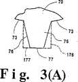
図1および図2に関して、フレキシブルグラファイトシートの形態にある膨脹グラファイト粒子の圧縮材料を10で示す。フレキシブルグラファイトシート10は、通路20を備えており、この通路は、好ましくは図5および8の67で示すような平滑な側面を有し、フレキシブルグラファイトシート10の平行な対向する表面30、40の間を通っている。通路20は、好ましくは対向する表面の一方30に開口部50を有し、その開口部50は、反対側の表面40にある開口部60よりも大きい。通路20は、図2(A)、2(B)、2(C)で20’〜20'''で示すような異なった構造を有することができ、これらの構造は、図1(A)および2(A)、2(B)、2(C)で75、175、275、375で示すような異なった形状の、平らな末端を有する突起部品を使用して形成され、これらの突起部品は、金属、例えば鋼、から形成され、図3に示す衝撃装置のプレス加工ローラー70と一体化され、そこから伸びている。77、177、277、377で示す突起部品の平滑で平らな末端、およびローラー70の平滑な座面73、およびローラー72の平滑な座面78(あるいは平らな金属板79)が、フレキシブルグラファイトシート中のグラファイトを確実に変形し、移動させる、すなわち通路形成衝撃により、粗い、または雑な縁部または破片は生じないのが好ましい。好ましい突起部品は、圧縮ローラー70から遠ざかる方向で断面が減少して行き、シートの、最初に衝撃を受ける側で、大きな通路開口部を与える。通路開口部60を取り囲んで平滑な、障害にならない表面63が形成されることにより、流体は、(67で)平滑な側面を有する通路20の中に、およびその通路を通って自由に流れることができる。 With reference to FIGS. 1 and 2, a compressed material of expanded graphite particles in the form of a flexible graphite sheet is indicated at 10. The
好ましい実施態様では、対向する表面の一方にある開口部が反対側の表面にある通路開口部より、例えば面積で1〜200倍大きく、76、276、376で示すような、側面が収束する突起部品を使用することにより、得られる。通路20は、フレキシブルグラファイトシート10中に複数の予め決められた位置で、シート10中の予め決められた位置における機械的衝撃により、図3に示すような機構を使用して形成するが、この機構は、一対の鋼製ローラー70、72を含んでなり、ローラーの一方が、先端を切り取った、すなわち平らな末端を有するプリズム形突起75を有し、この突起がフレキシブルグラファイトシート10の表面30に衝撃を与え、グラファイトを移動させ、シート10に貫通し、開いた通路20を形成する。実際には、両方のローラー70、72が「重なり合っていない」突起を備えることができ、平滑な表面を有するローラー72の代わりに、79で示す平らな金属板を使用することもできる。図4は、フレキシブルグラファイトシート110の拡大図であり、圧縮された膨脹グラファイト粒子80の典型的な、対向表面130、140に対して実質的に平行な配向を示す。膨脹グラファイト粒子80のこの配向により、フレキシブルグラファイトシートにおける特性の異方性が得られ、シートの導電性および熱的伝導性が、対向する表面130、140に対して横方向(「c」方向)で、対向する表面130、140に対して平行な方向(「a」方向)よりも実質的に低くなる。フレキシブルグラファイトシート10に衝撃を与えて通路20を形成する際、図3に示すように、平らな末端を有する(77で)突起75が移動し、ローラー70の平滑な表面73に突き当たる時に、グラファイトを押し退け、図5の800で示すように、膨脹グラファイト粒子80の平行な配向をかき乱し、変形させる。通路20に隣接するこの区域800は、平行な配向が斜めの、平行ではない配向にかき乱されている様子を示し、これは100X以上の拡大で光学的に観察することができる。その結果、押し退けられたグラファイトは、図5に示すように、ローラー70の隣接する突起75の側面76および平滑な表面73により「ダイ成形」されている。これによってフレキシブルグラファイトシート10の異方性が低下し、対向する表面30、40に対して横方向で電気的および熱的伝導性が増加する。同様の効果は、円錐台形の、および側面が平行で末端が平らな釘形の突起275および175でも達成される。 In a preferred embodiment, the opening on one of the opposing surfaces is 1 to 200 times larger in area than the passage opening on the opposite surface, such as 76, 276, 376, with converging sides. It is obtained by using parts. The
有利なことに、図9および10に示すように、グラファイトシート10の縁部には、孔を開けなくてもよい。つまり、シート10の縁部には通路20を形成せず、密封目的のために比較的にガス不透過性の縁部を与えることができる。通路20を形成しない縁部の量は、厳密でなくてよいが、シート10の縁部から内側に好ましくは少なくとも約5%、より好ましくは少なくとも約10%、は通路20を持たない。 Advantageously, as shown in FIGS. 9 and 10, the edges of the
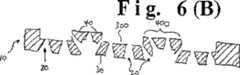
本発明の実施では、図6および6(A)に関して、図1に示すように横断型流体通路20を有するガス透過性のフレキシブルグラファイトシート10は、その上側表面30に連続的な上が開いた溝300、流体入口303および流体出口305を備え、ガス拡散電極610を構成する。図6(B)は、開溝300が反対側の表面40に形成されている配置を示す。本発明の溝300は、堅い金属ダイを、図2に示す型のフレキシブルグラファイトシート材料、すなわち流体通路20が表面30と表面40の間に通っているフレキシブルグラファイトシート、の上に押し付けることにより形成される。好ましい実施態様では、ダイが、ダイと接触する表面に、溝床310および溝ランドまたは壁320により形成される連続的な開いた溝300を形成する。しかし、別の実施態様では、溝300は、いずれかの特定のパターン、例えば効率または他の特徴を最適化するために通路20と共同するように設計されたパターン、で形成することができる。厚さが0.006インチ〜0.125インチのフレキシブルグラファイトのシートでは、深さが0.003インチ〜0.115インチであり、床310の幅が0.020インチ〜0.250インチであり、幅0.010インチ〜0.060インチの壁320により分離された溝300が好適である。In the practice of the present invention, with reference to FIGS. 6 and 6A, a gas permeable
重要なのは、通路20を形成した後のシート10中に開溝300を形成すると、シート10は、図6(A)および6(B)に示すように、断面が「コルゲート状」または波形になることである。つまり、壁320は、中空ではなく、逆「u」字形にほぼ等しくなる。従って、通路20は、溝床310でシート10を通して伸びるだけではなく、図に示すように、壁320の表面全体でシート10の一方の表面から他方の表面にも伸びることができる。このようにして、ガス、例えば燃料電池燃料または酸素、の自由流動が促進され、ガスが露出される触媒/メンブランの有効表面積が増大する。その上、通路20は、シート10の面に対して様々な角度で壁320を通って伸びるので、壁320の「内側」に向かう通路20を通って流れるガスの乱流が強化され、燃料電池の反応を促進することができる。 Importantly, when an
図7および8に示す装置は、フレキシブルグラファイト610の溝を形成したガス透過性物体と、フレキシブルグラファイトカバー部品310の組合せの形態にある電極630である。 The apparatus shown in FIGS. 7 and 8 is an
図7および8に示すカバー部品330は、比較的高い密度、例えば0.9〜1.5g/ccにロール圧縮およびカレンダー加工した薄いフレキシブルグラファイトシート(0.003インチ〜0.010インチ)である。ロール圧縮およびカレンダー加工したシート310は、熱伝導率に関して異方性の程度が常に高い。フレキシブルグラファイトシートの面における方向(「a」方向)における熱伝導率は、典型的にはフレキシブルグラファイトシートを通した方向(「c」方向)における熱伝導率の30〜70倍である。その結果、図9、10、10(A)に示す燃料電池500で、例えば触媒603で電流のために発生した熱は、ガス拡散電極610を通り、接触している連続的なフレキシブルグラファイトシートカバー部品310に伝えられ、次いでグラファイトシート310の対向表面311、314に対して平行に、この方向(「a」)における高い熱伝導率のために、フレキシブルグラファイトシートカバー部品310の縁部312に急速に伝えられ、そこで熱は対流により容易に放散される。これによって、燃料電池の積重構造中に冷却用のセルまたは部品を組み込む必要性が最少に抑えられる。 The cover component 330 shown in FIGS. 7 and 8 is a thin flexible graphite sheet (0.003 inch to 0.010 inch) that has been roll compressed and calendered to a relatively high density, eg, 0.9 to 1.5 g / cc. . Roll compressed and
フレキシブルグラファイトシートカバー部品310とガス拡散電極610との間に最適な結合を達成するには、グラファイトシートカバー部品330に熱硬化性樹脂を含浸させ(例えば性フェノール系樹脂のアルコール溶液に浸漬することにより)、次いで樹脂含有フレキシブルグラファイトシート30を、ガス拡散電極610の溝形成した表面30または40の隆起した部分400と接触するように配置し、加熱して樹脂を硬化させ、溝形成した表面のランド400で結合部410を形成する。これは、樹脂含浸したカバー部品310を平らな金属表面上に置き、ガス拡散電極610を樹脂含浸したカバー部品310に軽く押し付けながら、樹脂を硬化させ、結合させるのに十分な温度、典型的には170℃〜400℃、にカバー部品310を加熱することにより都合良く達成される。あるいは、ガス拡散層のダイ形成した溝形成表面の隆起した部分400に類似の樹脂を塗布し、上記のように配置したカバー部品を硬化させることにより結合させることもできる。 In order to achieve optimum bonding between the flexible graphite
図9、図10および図10(A)は、電気化学的Fuel Cell 500の基本的部品を図式的に示すが、より完全な詳細は、それぞれここに参考として含める米国特許第4,988,583号および第5,300,370号およびPCTWO95/16287号(1995年6月15日)に開示されている。 FIGS. 9, 10 and 10A schematically illustrate the basic components of an
図9、図10および図10(A)に関して、全体的に500で示す燃料電池は、プラスチック、例えば固体重合体イオン交換メンブラン550触媒、表面601、603で塗布された、例えば図10(A)に示すように白金600を塗布された触媒、および有孔の表面に溝形成されたフレキシブルグラファイトシート610を、カバー部品310との組合せで含んでなる。加圧された燃料がガス拡散電極610の溝300を通して循環され、加圧された酸化体がガス拡散電極1610の溝1300を通して循環される。作動の際、ガス拡散電極610はアノードになり、ガス拡散電極1610はカソードになり、その結果、電位、すなわち電圧がアノード610とカソード1610との間に発生する。上記の電気化学的燃料電池は、上記の米国特許第5,300,370号に記載されているように、他の燃料電池と燃料電池積重構造中に組み合わされて電流を発生し、所望のレベルの電力を供給する。 9, 10 and 10A, a fuel cell, generally designated 500, is coated with plastic, eg, a solid polymer
燃料電池500の作動では、電極610、1610は、イオン交換メンブランに隣接する燃料および酸化体流体、例えば水素および酸素、に対して多孔質であり、これらの成分を表面溝300および通路20から容易に通過させ、図10(A)に示すような触媒600と接触させ、水素に由来するプロトンを、イオン交換メンブラン550を通して移動させる。本発明のガス透過性電極610、1610では、横方向の通路20が、電極610、1610の表面溝300、1300に隣接して配置されているので、加圧されたガスが表面溝300、1300から中を通り、通路20から外に出て、触媒600と接触する。 In operation of the
本発明では、通路に隣接する厚さが約0.003インチ〜0.015インチであり、密度が約0.5〜1.5グラム/立方センチメートルであるフレキシブルグラファイトシートに対して、好ましい通路密度(または数)は約1000〜3000通路/平方インチである。より好ましくは、通路密度は少なくとも約1200、最も好ましくは少なくとも約2300である。好ましい通路サイズは、大きい方と小さい方の通路開口部の面積比が約50:1〜150:1であり、上が開いた溝の幅が好ましくは約0.020〜0.125であり、シートの厚さの少なくとも約半分である。 In the present invention, for a flexible graphite sheet having a thickness adjacent to the passage of about 0.003 inches to 0.015 inches and a density of about 0.5 to 1.5 grams per cubic centimeter, the preferred passage density ( Or number) is about 1000 to 3000 passages per square inch. More preferably, the passage density is at least about 1200, most preferably at least about 2300. A preferred passage size is that the area ratio of the larger and smaller passage openings is about 50: 1 to 150: 1, and the width of the open groove is preferably about 0.020 to 0.125, At least about half the thickness of the sheet.
燃料電池で使用した場合の本発明の他の利点は、電極周辺部における放熱性が高いことであり、これによって電池中における冷却部品の必要性が最少に抑えられると共に、比較的薄い電極が得られ、一方または両方のフローフィールドプレートの必要性が無くなることである。 Another advantage of the present invention when used in a fuel cell is high heat dissipation at the periphery of the electrode, which minimizes the need for cooling components in the cell and provides a relatively thin electrode. The need for one or both flow field plates is eliminated.
上記の説明は、当業者が本発明を実施し得ることを意図している。この説明を読むことにより当業者が自明の可能な変形や修正のすべてを詳細に説明することは意図していない。しかしながら、そのような修正および変形のすべては、請求項により規定される本発明の範囲内に入る。状況が特に反対のことを示していない限り、請求項は、記載する部品および工程を、本発明が意図する目的に有効であるあらゆる配置または順序を包含する。 The above description is intended to enable one skilled in the art to practice the invention. It is not intended to be a detailed description of all possible variations and modifications obvious to those skilled in the art upon reading this description. However, all such modifications and variations fall within the scope of the invention as defined by the claims. Unless the context indicates otherwise, the claims include the arrangement and order of the parts and steps described which are valid for the purposes intended by the present invention.
Claims (19)
Translated fromJapanese前記シート状の膨脹グラファイト粒子の圧縮材料には、前記第一表面と前記第二表面との間を貫通する複数の流体通路が設けられ、
前記第一表面および前記第二表面の一方に、前記シート状の膨脹グラファイト粒子の圧縮材料内で前記複数の流体通路に通じる開溝が形成され、
前記開溝が、溝床と、溝壁と、を有し、そして、
前記シート状の膨脹グラファイト粒子の圧縮材料には、前記溝壁を通って伸びる流体通路が設けられている
ことを特徴とするグラファイト製品。A graphite product for use in a gas diffusion layer for a PEM fuel cell, comprising a compressed material of sheet-like expanded graphite particles having opposing first and second surfaces,
The compressed material of the sheet-like expanded graphite particles is provided with a plurality of fluid passages penetrating between the first surface and the second surface,
One of the first surface and the second surface is formed with open grooves that communicate with the plurality of fluid passages in the compressed material of the sheet-like expanded graphite particles,
The open groove has a groove floor and a groove wall; and
The graphite product, wherein the compressed material of the sheet-like expanded graphite particles is provided with a fluid passage extending through the groove wall .
(ii)前記開溝が形成された前記表面に結合されて前記開溝のカバーとして用いられるフレキシブルグラファイトのシートと、
を備えた、PEM燃料電池用ガス拡散層に用いる基材であって、
前記開溝が、前記シート状の膨脹グラファイト粒子の圧縮材料内で前記複数の流体通路に通じ、
前記開溝が、溝床と、溝壁と、を有し、そして、
前記シート状の膨脹グラファイト粒子の圧縮材料には、前記溝壁を通って伸びる流体通路が設けられている
ことを特徴とする基材。(i) formed on one of the first surface and the second surface facing each other, a plurality of fluid passages penetrating between the first surface and the second surface, and the first surface and the second surface A compressed material of sheet-like expanded graphite particles having an open groove;
(ii) a sheet of flexible graphite that is used as a cover for the groove by being bonded to the surface on which the groove is formed;
A base material used for a gas diffusion layer for a PEM fuel cell, comprising:
The open grooves communicate with the plurality of fluid passages in the compressed material of the sheet-like expanded graphite particles;
The open groove has a groove floor and a groove wall; and
The base material, wherein the compressed material of the sheet-like expanded graphite particles is provided with a fluid passage extending through the groove wall .
対向する第一表面および第二表面を有するシート状の膨脹グラファイト粒子の圧縮材料を用意するステップと、
前記シート状の膨脹グラファイト粒子の圧縮材料に前記第一表面と前記第二表面との間を貫通する複数の流体通路を形成するステップと、
前記第一表面および前記第二表面の一方に、前記シート状の膨脹グラファイト粒子の圧縮材料内で前記複数の流体通路に通じる開溝を形成するステップと、を含み、
前記開溝が、溝床と、溝壁と、を有し、そして、
前記シート状の膨脹グラファイト粒子の圧縮材料には、前記溝壁を通って伸びる流体通路が設けられている
ことを特徴とする方法。A method of forming a graphite product used for a gas diffusion layer for a PEM fuel cell,
Providing a compressed material of sheet-like expanded graphite particles having opposing first and second surfaces;
Forming a plurality of fluid passages penetrating between the first surface and the second surface in the compressed material of the sheet-like expanded graphite particles;
One of said first surface and said second surface,viewed including the steps of: forming a open groove communicating with the plurality of fluid passages within the compacted material of the sheet-like expanded graphiteparticles,
The open groove has a groove floor and a groove wall; and
A method, wherein the compressed material of the sheet-like expanded graphite particles is provided with a fluid passage extending through the groove wall .
Applications Claiming Priority (3)
| Application Number | Priority Date | Filing Date | Title |
|---|---|---|---|
| US10/260,748US20040072055A1 (en) | 2000-04-14 | 2002-09-30 | Graphite article useful as a fuel cell component substrate |
| US10/260,748 | 2002-09-30 | ||
| PCT/US2003/030513WO2004031497A2 (en) | 2002-09-30 | 2003-09-26 | Graphite article useful as a fuel cell component substrate |
Publications (2)
| Publication Number | Publication Date |
|---|---|
| JP2006501621A JP2006501621A (en) | 2006-01-12 |
| JP4851091B2true JP4851091B2 (en) | 2012-01-11 |
Family
ID=32068198
Family Applications (1)
| Application Number | Title | Priority Date | Filing Date |
|---|---|---|---|
| JP2004541781AExpired - Fee RelatedJP4851091B2 (en) | 2002-09-30 | 2003-09-26 | Graphite product used for gas diffusion layer for PEM fuel cell, method for forming the graphite product, and base material used for gas diffusion layer for PEM fuel cell |
Country Status (8)
| Country | Link |
|---|---|
| US (1) | US20040072055A1 (en) |
| EP (1) | EP1546475A4 (en) |
| JP (1) | JP4851091B2 (en) |
| KR (1) | KR101178305B1 (en) |
| CN (1) | CN100438137C (en) |
| AU (1) | AU2003276993A1 (en) |
| CA (1) | CA2499499A1 (en) |
| WO (1) | WO2004031497A2 (en) |
Families Citing this family (17)
| Publication number | Priority date | Publication date | Assignee | Title |
|---|---|---|---|---|
| EP1562245A4 (en)* | 2002-11-05 | 2007-09-12 | Shishiai Kk | Fuel cell coolant |
| AU2003248060A1 (en) | 2003-07-11 | 2005-01-28 | Shishiai-Kabushikigaisha | Cooling fluid composition for fuel battery |
| JP2005327613A (en)* | 2004-05-14 | 2005-11-24 | Aisin Seiki Co Ltd | Fuel cell |
| JP4168047B2 (en)* | 2005-08-16 | 2008-10-22 | 日本ピラー工業株式会社 | Heat transfer sheet and method of manufacturing heat transfer sheet |
| EP1791203B1 (en) | 2005-11-29 | 2010-05-19 | Samsung SDI Co., Ltd. | Direct Oxidation Fuel Cell |
| KR100728789B1 (en) | 2005-11-29 | 2007-06-19 | 삼성에스디아이 주식회사 | Direct oxidation fuel cell |
| KR100728122B1 (en) | 2005-11-29 | 2007-06-13 | 삼성에스디아이 주식회사 | Direct oxidation fuel cell |
| EP2357695B1 (en)* | 2009-10-13 | 2015-08-12 | Panasonic Intellectual Property Management Co., Ltd. | Fuel cell and method for manufacturing same |
| US9048468B2 (en)* | 2010-09-17 | 2015-06-02 | GM Global Technology Operations LLC | Method for forming channels on diffusion media for a membrane humidifier |
| JP5907441B2 (en)* | 2012-04-06 | 2016-04-26 | 日産自動車株式会社 | Fuel cell |
| US9706684B2 (en) | 2013-12-26 | 2017-07-11 | Terrella Energy Systems Ltd. | Exfoliated graphite materials and composite materials and devices for thermal management |
| US9700968B2 (en) | 2013-12-26 | 2017-07-11 | Terrella Energy Systems Ltd. | Apparatus and methods for processing exfoliated graphite materials |
| US20150311540A1 (en)* | 2014-04-29 | 2015-10-29 | Energyor Technologies Inc. | Method for producing fluid flow field plates |
| WO2016051633A1 (en)* | 2014-09-29 | 2016-04-07 | パナソニックIpマネジメント株式会社 | Gas diffusion layer for fuel cell, fuel cell, and formation method for gas diffusion layer for fuel cell |
| CN105134720A (en)* | 2015-08-25 | 2015-12-09 | 江苏神州碳制品有限公司 | Graphite plate bonding technology |
| US11840013B2 (en) | 2018-02-27 | 2023-12-12 | Matthews International Corporation | Graphite materials and devices with surface micro-texturing |
| CN112959725B (en)* | 2021-02-02 | 2022-09-06 | 上海神力科技有限公司 | Roll forming method of flexible graphite polar plate of fuel cell |
Family Cites Families (22)
| Publication number | Priority date | Publication date | Assignee | Title |
|---|---|---|---|---|
| GB991581A (en)* | 1962-03-21 | 1965-05-12 | High Temperature Materials Inc | Expanded pyrolytic graphite and process for producing the same |
| US4649091A (en)* | 1982-06-23 | 1987-03-10 | United Technologies Corporation | Fuel cell battery with improved membrane cooling |
| US4895713A (en)* | 1987-08-31 | 1990-01-23 | Union Carbide Corporation | Intercalation of graphite |
| US4988583A (en)* | 1989-08-30 | 1991-01-29 | Her Majesty The Queen As Represented By The Minister Of National Defence Of Her Majesty's Canadian Government | Novel fuel cell fluid flow field plate |
| US5300376A (en)* | 1992-09-15 | 1994-04-05 | The United States Of America As Represented By The Secretary Of The Army | Highly conductive electrolyte for use in an ambient temperature rechargeable lithium battery and ambient temperature rechargeable lithium battery including said electrolyte |
| US5300370A (en)* | 1992-11-13 | 1994-04-05 | Ballard Power Systems Inc. | Laminated fluid flow field assembly for electrochemical fuel cells |
| US5527363A (en)* | 1993-12-10 | 1996-06-18 | Ballard Power Systems Inc. | Method of fabricating an embossed fluid flow field plate |
| US6242124B1 (en)* | 1995-07-05 | 2001-06-05 | Nisshinbo Industries, Inc. | Separator for polymer electrolyte fuel cells and processes for production thereof |
| FR2754740B1 (en)* | 1996-10-21 | 1998-12-04 | Elf Aquitaine | ACTIVE COMPOSITE WITH LAMINATED STRUCTURE COMPRISING AN ACTIVE AGENT IN THE FORM OF GRANULES |
| US5902762A (en)* | 1997-04-04 | 1999-05-11 | Ucar Carbon Technology Corporation | Flexible graphite composite |
| US5885728A (en)* | 1997-04-04 | 1999-03-23 | Ucar Carbon Technology Corporation | Flexible graphite composite |
| US5976726A (en)* | 1997-05-01 | 1999-11-02 | Ballard Power Systems Inc. | Electrochemical cell with fluid distribution layer having integral sealing capability |
| US5976727A (en)* | 1997-09-19 | 1999-11-02 | Ucar Carbon Technology Corporation | Electrically conductive seal for fuel cell elements |
| JP2922492B1 (en)* | 1998-03-16 | 1999-07-26 | 日本ピラー工業株式会社 | Filter member and filter using the same |
| WO1999063610A1 (en)* | 1998-06-02 | 1999-12-09 | Matsushita Electric Industrial Co., Ltd. | Polymer electrolyte fuel cell and method of manufacture thereof |
| US6037074A (en)* | 1998-07-07 | 2000-03-14 | Ucar Carbon Technology Corporation | Flexible graphite composite for use in the form of a fuel cell flow field plate |
| US6087034A (en)* | 1998-07-09 | 2000-07-11 | Ucar Graph-Tech Inc. | Flexible graphite composite |
| JP2001118587A (en)* | 1999-10-15 | 2001-04-27 | Toshiba Corp | Polymer electrolyte fuel cell and method of operating the same |
| US6413671B1 (en)* | 2000-04-10 | 2002-07-02 | Gaftech Inc. | Flexible graphite article and fuel cell electrode with enhanced electrical and thermal conductivity |
| JP3616787B2 (en)* | 2000-04-14 | 2005-02-02 | 三興コントロール株式会社 | Fuel cell stack separator and method of manufacturing the same |
| BR0017203B1 (en)* | 2000-04-14 | 2013-03-05 | graphite article and electrode for fuel electrochemical cell. | |
| US6566004B1 (en)* | 2000-08-31 | 2003-05-20 | General Motors Corporation | Fuel cell with variable porosity gas distribution layers |
- 2002
- 2002-09-30USUS10/260,748patent/US20040072055A1/ennot_activeAbandoned
- 2003
- 2003-09-26CNCNB038234092Apatent/CN100438137C/ennot_activeExpired - Fee Related
- 2003-09-26CACA002499499Apatent/CA2499499A1/ennot_activeAbandoned
- 2003-09-26WOPCT/US2003/030513patent/WO2004031497A2/enactiveApplication Filing
- 2003-09-26EPEP03799294Apatent/EP1546475A4/ennot_activeWithdrawn
- 2003-09-26AUAU2003276993Apatent/AU2003276993A1/ennot_activeAbandoned
- 2003-09-26JPJP2004541781Apatent/JP4851091B2/ennot_activeExpired - Fee Related
- 2003-09-26KRKR1020057005413Apatent/KR101178305B1/ennot_activeExpired - Fee Related
Also Published As
| Publication number | Publication date |
|---|---|
| US20040072055A1 (en) | 2004-04-15 |
| KR101178305B1 (en) | 2012-08-29 |
| CN1689176A (en) | 2005-10-26 |
| WO2004031497A3 (en) | 2004-06-17 |
| KR20050056219A (en) | 2005-06-14 |
| AU2003276993A8 (en) | 2004-04-23 |
| WO2004031497A2 (en) | 2004-04-15 |
| EP1546475A2 (en) | 2005-06-29 |
| EP1546475A4 (en) | 2007-12-05 |
| CA2499499A1 (en) | 2004-04-15 |
| AU2003276993A1 (en) | 2004-04-23 |
| CN100438137C (en) | 2008-11-26 |
| JP2006501621A (en) | 2006-01-12 |
Similar Documents
| Publication | Publication Date | Title |
|---|---|---|
| US6673289B2 (en) | Manufacture of materials from graphite particles | |
| KR101009500B1 (en) | Heat spreader for flexible graphite flooring | |
| JP4851091B2 (en) | Graphite product used for gas diffusion layer for PEM fuel cell, method for forming the graphite product, and base material used for gas diffusion layer for PEM fuel cell | |
| US20020164483A1 (en) | Graphite article having predetermined anisotropic characteristics and process therefor | |
| US6521369B1 (en) | Flooding-reducing fuel cell electrode | |
| JP2007525341A (en) | Treatment and method of flexible graphite material | |
| US6902841B2 (en) | Hydrophobic fuel cell electrode | |
| US6503652B2 (en) | Fuel cell assembly method with selective catalyst loading | |
| US20030025234A1 (en) | Hydrophobic fuel cell component | |
| US6613252B2 (en) | Molding of materials from graphite particles | |
| JP2005531905A (en) | Bipolar plate assembly | |
| US20030108731A1 (en) | Molding of fluid permeable flexible graphite components for fuel cells | |
| US6716381B2 (en) | Process for preparing embossed flexible graphite article | |
| US7241409B2 (en) | Gas permeable flexible graphite sheet material and process therefor | |
| US20050104243A1 (en) | Method of forming impressions in a flexible graphite material | |
| US7341781B2 (en) | Material useful for preparing embossed flexible graphite article | |
| JP2007516080A (en) | Method for improving adhesion of coating to flexible graphite material | |
| TW592968B (en) | Material and process useful for preparing embossed flexible graphite article |
Legal Events
| Date | Code | Title | Description |
|---|---|---|---|
| A621 | Written request for application examination | Free format text:JAPANESE INTERMEDIATE CODE: A621 Effective date:20060925 | |
| A711 | Notification of change in applicant | Free format text:JAPANESE INTERMEDIATE CODE: A712 Effective date:20080529 | |
| A131 | Notification of reasons for refusal | Free format text:JAPANESE INTERMEDIATE CODE: A131 Effective date:20100323 | |
| A521 | Request for written amendment filed | Free format text:JAPANESE INTERMEDIATE CODE: A523 Effective date:20100603 | |
| A131 | Notification of reasons for refusal | Free format text:JAPANESE INTERMEDIATE CODE: A131 Effective date:20101207 | |
| A601 | Written request for extension of time | Free format text:JAPANESE INTERMEDIATE CODE: A601 Effective date:20110307 | |
| A602 | Written permission of extension of time | Free format text:JAPANESE INTERMEDIATE CODE: A602 Effective date:20110325 | |
| A521 | Request for written amendment filed | Free format text:JAPANESE INTERMEDIATE CODE: A523 Effective date:20110404 | |
| TRDD | Decision of grant or rejection written | ||
| A01 | Written decision to grant a patent or to grant a registration (utility model) | Free format text:JAPANESE INTERMEDIATE CODE: A01 Effective date:20111018 | |
| A01 | Written decision to grant a patent or to grant a registration (utility model) | Free format text:JAPANESE INTERMEDIATE CODE: A01 | |
| A61 | First payment of annual fees (during grant procedure) | Free format text:JAPANESE INTERMEDIATE CODE: A61 Effective date:20111020 | |
| R150 | Certificate of patent or registration of utility model | Free format text:JAPANESE INTERMEDIATE CODE: R150 | |
| FPAY | Renewal fee payment (event date is renewal date of database) | Free format text:PAYMENT UNTIL: 20141028 Year of fee payment:3 | |
| LAPS | Cancellation because of no payment of annual fees |