JP4850907B2 - Device for treating spinal stenosis - Google Patents
Device for treating spinal stenosisDownload PDFInfo
- Publication number
- JP4850907B2 JP4850907B2JP2008525260AJP2008525260AJP4850907B2JP 4850907 B2JP4850907 B2JP 4850907B2JP 2008525260 AJP2008525260 AJP 2008525260AJP 2008525260 AJP2008525260 AJP 2008525260AJP 4850907 B2JP4850907 B2JP 4850907B2
- Authority
- JP
- Japan
- Prior art keywords
- maintenance member
- maintenance
- main body
- body end
- body structure
- Prior art date
- Legal status (The legal status is an assumption and is not a legal conclusion. Google has not performed a legal analysis and makes no representation as to the accuracy of the status listed.)
- Active
Links
- 208000005198spinal stenosisDiseases0.000titleclaimsdescription10
- 238000000034methodMethods0.000claimsdescription135
- 230000008569processEffects0.000claimsdescription122
- 239000007943implantSubstances0.000claimsdescription62
- 239000000463materialSubstances0.000claimsdescription52
- 238000003780insertionMethods0.000claimsdescription36
- 230000037431insertionEffects0.000claimsdescription36
- 230000007246mechanismEffects0.000claimsdescription24
- 239000000470constituentSubstances0.000claimsdescription8
- 238000012423maintenanceMethods0.000claims88
- 238000000926separation methodMethods0.000description21
- 210000004872soft tissueAnatomy0.000description9
- 230000036961partial effectEffects0.000description8
- 210000001519tissueAnatomy0.000description7
- 229910052751metalInorganic materials0.000description6
- 239000002184metalSubstances0.000description6
- 210000003205muscleAnatomy0.000description5
- 230000000452restraining effectEffects0.000description5
- 208000031481Pathologic ConstrictionDiseases0.000description4
- 210000003484anatomyAnatomy0.000description4
- 239000000919ceramicSubstances0.000description4
- 239000003550markerSubstances0.000description4
- 150000002739metalsChemical class0.000description4
- 230000036262stenosisEffects0.000description4
- 208000037804stenosisDiseases0.000description4
- 238000012986modificationMethods0.000description3
- 230000004048modificationEffects0.000description3
- 230000002093peripheral effectEffects0.000description3
- 239000004033plasticSubstances0.000description3
- 229920003023plasticPolymers0.000description3
- 229920000642polymerPolymers0.000description3
- 238000001356surgical procedureMethods0.000description3
- 230000000007visual effectEffects0.000description3
- 0C(*1)[C@@]2C1CCCC2Chemical compoundC(*1)[C@@]2C1CCCC20.000description2
- RTAQQCXQSZGOHL-UHFFFAOYSA-NTitaniumChemical compound[Ti]RTAQQCXQSZGOHL-UHFFFAOYSA-N0.000description2
- 229910045601alloyInorganic materials0.000description2
- 239000000956alloySubstances0.000description2
- 229910052782aluminiumInorganic materials0.000description2
- XAGFODPZIPBFFR-UHFFFAOYSA-NaluminiumChemical compound[Al]XAGFODPZIPBFFR-UHFFFAOYSA-N0.000description2
- 238000005452bendingMethods0.000description2
- 239000000560biocompatible materialSubstances0.000description2
- 210000000988bone and boneAnatomy0.000description2
- 239000002131composite materialSubstances0.000description2
- 229920001971elastomerPolymers0.000description2
- 230000001747exhibiting effectEffects0.000description2
- 230000006870functionEffects0.000description2
- 238000009434installationMethods0.000description2
- 239000005060rubberSubstances0.000description2
- 239000010935stainless steelSubstances0.000description2
- 229910001220stainless steelInorganic materials0.000description2
- 238000006467substitution reactionMethods0.000description2
- 229910052719titaniumInorganic materials0.000description2
- 239000010936titaniumSubstances0.000description2
- FRVDNDJAEGZTAU-UHFFFAOYSA-NC(C1C2)C(C3)C11C2C=C3C1Chemical compoundC(C1C2)C(C3)C11C2C=C3C1FRVDNDJAEGZTAU-UHFFFAOYSA-N0.000description1
- 208000007623LordosisDiseases0.000description1
- 208000027418Wounds and injuryDiseases0.000description1
- 238000007792additionMethods0.000description1
- 238000006073displacement reactionMethods0.000description1
- 238000002224dissectionMethods0.000description1
- 230000007613environmental effectEffects0.000description1
- 210000003195fasciaAnatomy0.000description1
- 208000014674injuryDiseases0.000description1
- 239000004816latexSubstances0.000description1
- 229920000126latexPolymers0.000description1
- 210000003041ligamentAnatomy0.000description1
- 230000000670limiting effectEffects0.000description1
- 230000014759maintenance of locationEffects0.000description1
- 230000013011matingEffects0.000description1
- 230000004220muscle functionEffects0.000description1
- 229920000515polycarbonatePolymers0.000description1
- 239000004417polycarbonateSubstances0.000description1
- 229920001692polycarbonate urethanePolymers0.000description1
- 238000011084recoveryMethods0.000description1
- 230000002829reductive effectEffects0.000description1
- 230000004044responseEffects0.000description1
- 230000000717retained effectEffects0.000description1
- 230000000087stabilizing effectEffects0.000description1
- 230000001954sterilising effectEffects0.000description1
- 238000004659sterilization and disinfectionMethods0.000description1
- 230000008733traumaEffects0.000description1
- 239000011800void materialSubstances0.000description1
Images


Classifications
- A—HUMAN NECESSITIES
- A61—MEDICAL OR VETERINARY SCIENCE; HYGIENE
- A61B—DIAGNOSIS; SURGERY; IDENTIFICATION
- A61B17/00—Surgical instruments, devices or methods
- A61B17/56—Surgical instruments or methods for treatment of bones or joints; Devices specially adapted therefor
- A61B17/58—Surgical instruments or methods for treatment of bones or joints; Devices specially adapted therefor for osteosynthesis, e.g. bone plates, screws or setting implements
- A61B17/68—Internal fixation devices, including fasteners and spinal fixators, even if a part thereof projects from the skin
- A61B17/70—Spinal positioners or stabilisers, e.g. stabilisers comprising fluid filler in an implant
- A61B17/7062—Devices acting on, attached to, or simulating the effect of, vertebral processes, vertebral facets or ribs ; Tools for such devices
- A61B17/7065—Devices with changeable shape, e.g. collapsible or having retractable arms to aid implantation; Tools therefor
- A—HUMAN NECESSITIES
- A61—MEDICAL OR VETERINARY SCIENCE; HYGIENE
- A61B—DIAGNOSIS; SURGERY; IDENTIFICATION
- A61B17/00—Surgical instruments, devices or methods
- A61B17/56—Surgical instruments or methods for treatment of bones or joints; Devices specially adapted therefor
- A61B17/58—Surgical instruments or methods for treatment of bones or joints; Devices specially adapted therefor for osteosynthesis, e.g. bone plates, screws or setting implements
- A61B17/68—Internal fixation devices, including fasteners and spinal fixators, even if a part thereof projects from the skin
- A61B17/84—Fasteners therefor or fasteners being internal fixation devices
- A61B17/846—Nails or pins, i.e. anchors without movable parts, holding by friction only, with or without structured surface
- A61B17/848—Kirschner wires, i.e. thin, long nails
- A—HUMAN NECESSITIES
- A61—MEDICAL OR VETERINARY SCIENCE; HYGIENE
- A61B—DIAGNOSIS; SURGERY; IDENTIFICATION
- A61B17/00—Surgical instruments, devices or methods
- A61B17/56—Surgical instruments or methods for treatment of bones or joints; Devices specially adapted therefor
- A61B17/58—Surgical instruments or methods for treatment of bones or joints; Devices specially adapted therefor for osteosynthesis, e.g. bone plates, screws or setting implements
- A61B17/88—Osteosynthesis instruments; Methods or means for implanting or extracting internal or external fixation devices
- A61B17/8897—Guide wires or guide pins
Landscapes
- Health & Medical Sciences (AREA)
- Orthopedic Medicine & Surgery (AREA)
- Life Sciences & Earth Sciences (AREA)
- Neurology (AREA)
- Surgery (AREA)
- Heart & Thoracic Surgery (AREA)
- Engineering & Computer Science (AREA)
- Biomedical Technology (AREA)
- Nuclear Medicine, Radiotherapy & Molecular Imaging (AREA)
- Medical Informatics (AREA)
- Molecular Biology (AREA)
- Animal Behavior & Ethology (AREA)
- General Health & Medical Sciences (AREA)
- Public Health (AREA)
- Veterinary Medicine (AREA)
- Prostheses (AREA)
Description
Translated fromJapanese本発明は被検体の脊柱を安定化する装置および方法に関するものであり、特に、互いに隣接し合う椎骨間に挿入する移植片に関するものである。 The present invention relates to an apparatus and method for stabilizing a spinal column of a subject, and more particularly to an implant that is inserted between adjacent vertebrae.
被検体の椎骨は棘突起として知られている後方に突出した部分を有している。脊柱が屈曲することで、互いに隣接し合う椎骨の棘突起は互いに向かって移動させられる。これは、脊柱管や脊柱孔の内部の空間を窄ませ、従って、痛みの原因となることがある。このような狭窄は、狭窄症(ステノーシス)として知られており、互いに隣接し合う棘突起相互の間の空間に移植片を利用することにより治療することができる。 The subject's vertebra has a posterior projecting portion known as a spinous process. As the spine is bent, the spinous processes of adjacent vertebrae are moved toward each other. This constricts the space inside the spinal canal and spinal foramen and can therefore cause pain. Such stenosis is known as stenosis and can be treated by using an implant in the space between adjacent spinous processes.
或る現行の移植片は複数の別個の部材片から作成されており、これら部材片は脊柱の両側から挿入する必要があるうえに、背位アプローチでは被検体にかなり幅広の開口部を設けるのに、左右の胸腰筋膜を両方とも切開するばかりか、多裂筋をそれぞれの付着部から剥ぎ取る必要があった。互いに隣接し合う椎骨の棘突起間に挿入する移植片でも、観血を最小限に抑えたアプローチで1個の切開部から挿入することができるとともに、椎体間の適所に堅固に保持することができる移植片を提供するのが望ましい。 Some current implants are made from a number of separate pieces that need to be inserted from both sides of the spine, and the dorsal approach provides a fairly wide opening in the subject. In addition, both the left and right thoracolumbar fascias had to be incised, and the multifidus had to be stripped from their respective attachments. Even implants that are inserted between adjacent spinous processes of vertebrae can be inserted through a single incision with a minimal invasive approach and should be firmly held in place between the vertebral bodies. It would be desirable to provide a graft that can be used.
本発明の装置は、第1端部と、第2端部と、前記第1端部と前記第2端部との間に位置するスリーブとを有する本体部を備えている。この装置の寸法および形状は、2個の互いに隣接し合う椎体の棘突起間に嵌合するように設定されている。スリーブは、複数の互いに異なる特性の(例えば、弾性係数が互いに異なる)素材で作られている単体部材片であってもよいし、または、そのような素材から作成された多数の構成部材を含んでいてもよい。この装置は、少なくとも2個の保持部材を有しており、これら保持部材は本体部に設置されるとともに、配備位置と後退位置との間で移動することができる。この装置はまた、第1端部および第2端部に接続することができるコネクタを有している。 The apparatus of the present invention includes a main body having a first end, a second end, and a sleeve positioned between the first end and the second end. The size and shape of this device is set to fit between the spinous processes of two adjacent vertebral bodies. The sleeve may be a single piece made of a plurality of materials having different characteristics (eg, having different elastic moduli), or may include a number of components made from such materials. You may go out. This apparatus has at least two holding members, and these holding members are installed on the main body and can move between a deployed position and a retracted position. The device also has a connector that can be connected to the first end and the second end.
作動器具(例えば、ネジ回し)を使って上述のコネクタを回転させることができる。コネクタを回転させることで第1端部と第2端部を互いに向けて移動させることができる。第1端部と第2端部が互いに向けて移動すると、保持部材が本体部から出て散開配備される。配備位置にくると、保持部材は本体部から外方向に張り出し、1個の椎骨の少なくとも1本の棘突起の両側に設置される。好ましい実施形態では、この装置には4個の保持部材が設けられており、互いに隣接し合う椎骨の2本の棘突起の両側に係合することができる。このような保持部材は移植片を脊柱に対して適所に保持することができる。 An actuator (eg, a screwdriver) can be used to rotate the connector described above. The first end and the second end can be moved toward each other by rotating the connector. When the first end and the second end move toward each other, the holding member comes out of the main body and is spread apart. When in the deployed position, the retaining member extends outwardly from the body and is placed on either side of at least one spinous process of one vertebra. In a preferred embodiment, the device is provided with four retaining members that can engage both sides of two spinous processes of adjacent vertebrae. Such a holding member can hold the graft in place against the spinal column.
代替の実施形態では、この装置は、第1端部と、第2端部と、前記第1端部と前記第2端部との間に設置することのできるスリーブとが設けられた本体部を備えている。第1端部は、そこを起点に細長い部材が延びており、2個以上の保持部材がこの第1端部と細長い部材に作動自在に付随するようになっている。好ましい実施形態では、2個の保持部材が第1端部に旋回自在に接続され、また別な2個の保持部材が細長い部材に旋回自在に接続される。コネクタは両端部に設置されて、コネクタの回転で両端部を互いに向けて引き寄せることができるようになっている。第2端部には1個以上の開口部が設けられており、これらの開口部に保持部材が通される。両端部が一緒に移動すると、細長い部材に接続されている保持部材が開口部を通って移動して第2端部の中に入り、本体部から離れるほうに張り出す。更に、第1端部に接続されている保持部材が移動してスリーブを押圧し、本体部から離れる方に張り出す。本体部と第1端部および第2端部は、互いに隣接し合う椎骨の棘突起がこれらホルダーの間に設置されるように載置される。また別な実施形態では、少なくとも1個の保持部材が(保持部材は2個であるのが好ましいが)両端部の各々に旋回自在に接続される。両端部が一緒に移動すると、保持部材が移動してスリーブを押圧し、本体部から離れる方向張り出す。 In an alternative embodiment, the device comprises a body portion provided with a first end, a second end, and a sleeve that can be placed between the first end and the second end. It has. An elongated member extends from the first end portion, and two or more holding members are operatively associated with the first end portion and the elongated member. In a preferred embodiment, two holding members are pivotally connected to the first end, and another two holding members are pivotally connected to the elongated member. The connectors are installed at both ends, and both ends can be drawn toward each other by the rotation of the connector. The second end portion is provided with one or more openings, and the holding member is passed through these openings. When both ends move together, the holding member connected to the elongated member moves through the opening and enters the second end and projects away from the body. Further, the holding member connected to the first end moves, presses the sleeve, and protrudes away from the main body. The main body portion, the first end portion, and the second end portion are placed such that the spinous processes of vertebrae adjacent to each other are placed between these holders. In another embodiment, at least one holding member (preferably two holding members) is pivotally connected to each of both ends. When both end portions move together, the holding member moves to press the sleeve, and protrudes away from the main body portion.
脊柱管狭窄症を治療する装置は、2個の互いに隣接し合う椎骨の棘突起間に嵌合するよう構成された移植片本体構造部と、この本体構造部に作動可能に付随する少なくとも2個の保持部材と、2個の保持部材を後退位置から、2個の互いに隣接し合う椎骨のうちの一方の棘突起すなわち第1の棘突起の傍で本体構造部から外方向に張り出す配備位置に移動させるように作動するシフト機構とを備えている。このシフト機構はネジである。シフト機構は本体構造部の内側に含まれる。本体構造部には第1端部および第2端部が設けられており、2個の保持部材は、配備位置にくると、本体構造部の両端から張り出し、または、本体構造部の互いに隣接し合う端部から張り出す。 An apparatus for treating spinal canal stenosis includes a graft body structure configured to fit between spinous processes of two adjacent vertebrae, and at least two operatively associated with the body structure And a deployment position in which the two holding members project outwardly from the body structure by the spinous process of one of the two adjacent vertebrae, ie, the first spinous process, from the retracted position. And a shift mechanism that operates so as to be moved. This shift mechanism is a screw. The shift mechanism is included inside the main body structure. The main body structure portion is provided with a first end portion and a second end portion, and the two holding members project from both ends of the main body structure portion or are adjacent to each other in the main body structure portion when in the deployed position. Overhang from the mating end.
更に、この装置の第3の保持部材および第4の保持部材は本体構造部に作動可能に付随しており、シフト機構は第3の保持部材および第4の保持部材をそれぞれの後退位置から、2個の互いに隣接し合う椎骨の他方の棘突起すなわち第2の棘突起の両側で本体構造部から外方向に張り出す配備位置まで駆動するように作動する。シフト機構は、軸線沿いに長手の細長いコネクタが本体構造部の内側に取付けられており、本体構造部の第1端部および第2端部は軸線沿いに互いに離隔されている。シフト機構は本体構造部の第1端部および第2端部が軸上で互いに向けて移動するように作動して、少なくとも2個の保持部材は、第1端部と第2端部の影響を受けて、両端部が軸上で互いに向かう方向に移動させられると、後退位置から配備位置へ移動する。保持部材は蝶番部材(ヒンジ)によって第1端部に取付けられる。少なくとも1個の保持部材が第1端部に固定され、第1端部と一緒に軸線方向に移動するとともに、第1端部が軸上を第2端部に向けて移動すると、第2端部に関して軸線方向に滑動する。第2端部は偏向して一方の保持部材を案内して後退位置から配備位置へ移動させるよう構成されている。 Further, the third holding member and the fourth holding member of the apparatus are operatively associated with the main body structure, and the shift mechanism moves the third holding member and the fourth holding member from their retracted positions. Actuating to drive a deployment position that projects outwardly from the body structure on either side of the other spinous process of the two adjacent vertebrae, the second spinous process. In the shift mechanism, a long and narrow connector along the axis is attached to the inside of the main body structure, and the first end and the second end of the main body structure are separated from each other along the axis. The shift mechanism operates so that the first end and the second end of the main body structure portion move toward each other on the shaft, and at least two holding members are affected by the first end and the second end. In response, when both ends are moved in a direction toward each other on the axis, the retracted position moves to the deployed position. The holding member is attached to the first end by a hinge member (hinge). When at least one holding member is fixed to the first end and moves in the axial direction together with the first end, and the first end moves on the axis toward the second end, the second end Slide axially with respect to the part. The second end is configured to deflect and guide one holding member to move from the retracted position to the deployed position.
保持部材は、第1端部と第2端部の間で延びるワイヤである。少なくとも1個の保持部材のワイヤは概ねU字型であり、両端が自由端になっている。自由端は第1端部に固定されて、第1端部が第2端部に相対的に軸線方向に移動すると、第1端部と一緒に移動するのが好ましい。第1端部および第2端部は各々に、ワイヤを偏向させるカムメンが設けられている。シフト機構は、長手方向軸線に沿う長手の細長いコネクタと、第1方向に第1端部とネジ結合するスクリューネジと、その反対方向に延びて第2方向に第2端部とネジ結合するスクリューネジとを備えている。 The holding member is a wire extending between the first end and the second end. The wire of the at least one holding member is generally U-shaped, and both ends are free ends. Preferably, the free end is fixed to the first end and moves together with the first end when the first end moves axially relative to the second end. Each of the first end and the second end is provided with a cammen for deflecting the wire. The shift mechanism includes a long and slender connector along the longitudinal axis, a screw screw that is screw-coupled to the first end in the first direction, and a screw that is screwed to the second end in the second direction. With screws.
本体部構造は第1端部と第2端部の間で軸上に配置されるスリーブを更に有している。スリーブは、2個の互いに隣接し合う椎骨の棘突起から付与される力を受けて、第1端部および第2端部に相対的に回転することができる。スリーブはまた、2個の互いに隣接し合う椎骨の棘突起から付与される力を受けて偏向することもできる。スリーブには両端部と、この両端部よりは厚みが大きい中間部がと設けられている。スリーブは、或る弾性係数を有している素材から形成された第1スリーブ部材と、これとは異なる弾性係数を有している素材から形成された第2スリーブ部材とを有している。シフト機構は、保持部材を配備位置から後退位置へ引っ込めるよう作動する。 The body structure further includes a sleeve disposed on the shaft between the first end and the second end. The sleeve can rotate relative to the first end and the second end under the force applied from the spinous processes of two adjacent vertebrae. The sleeve can also deflect under the force applied from the spinous processes of two adjacent vertebrae. The sleeve is provided with both end portions and an intermediate portion having a thickness larger than both end portions. The sleeve includes a first sleeve member formed from a material having a certain elastic coefficient and a second sleeve member formed from a material having a different elastic coefficient. The shift mechanism operates to retract the retaining member from the deployed position to the retracted position.
本体構造部には第1端部および第2端部が設けられており、シフト機構は、長手方向軸線に沿う長手の細長いコネクタと、外側スクリューネジが設けられた少なくとも1個の部分とを有しており、コネクタは回転するような構成になっている。第1端部および第2端部は各々に内側ネジが設けられて、細長いコネクタに取付けられる。保持部材は各々が、両端が自由端になった概ねU字型のワイヤを含んでおり、第1の保持部材の2つの自由端は本体構造部の第1端部に固定されており、第2の保持部材の2つの自由端は本体構造部の第2端部に固定されている。コネクタを第1の方向に回転させると、第1端部および第2端部はコネクタに沿って軸線方向に移動して緊密に近づき、両方の保持部材をコネクタの軸線に関して或る角度に配備する。 The body structure is provided with a first end and a second end, and the shift mechanism has a long and narrow connector along the longitudinal axis and at least one portion provided with an outer screw screw. The connector is configured to rotate. The first end and the second end are each provided with an inner screw and attached to the elongated connector. Each holding member includes a generally U-shaped wire with both ends being free ends, and the two free ends of the first holding member are fixed to the first end of the main body structure portion. Two free ends of the two holding members are fixed to the second end of the main body structure. When the connector is rotated in the first direction, the first end and the second end move axially along the connector and come closer together, deploying both retaining members at an angle with respect to the connector axis. .
また別な実施形態では、移植片は、本体構造部と少なくとも2個の保持部材とを備えており、本体構造部は2個の互いに隣接し合う椎骨の棘突起間に設置される構成の長手方向軸線に沿う長尺部を有しているとともに、2個の互いに隣接し合う椎骨の棘突起から付与される力を受けて移動する構成の周辺中間部を有しており、保持部材はその構成が、保持部材が軸線と概ね整列する後退位置から、保持部材が本体構造部から外へ軸線に関して或る角度で全体的に張り出して椎骨の棘突起の傍の部位に入り込む配備位置へ移動するよう設定されている。本体構造部の周辺中間部は、2個の互いに隣接し合う椎骨の棘突起から付与される力を受けると、保持部材に相対的に回転する構成にされている。脊柱移植片は、第1端部および第2端部を更に備えており、第1端部は2個の旋回接続部が設けられている張出部を有しており、第2端部は2個のガイド窓が設けられている。少なくとも2個の保持部材には近位端および遠位端が設けられており、保持部材は各々の遠位端が旋回接続部に旋回自在に接続されており、少なくとも2個の保持部材は寸法と形状が、両方の端部が互いに向けて移動すると、保持部材の近位端がガイド窓の中を通過するように設定されている。脊柱移植片は、遠位端および近位端が設けられている第3の保持部材と第4の保持部材を更に備えており、移植片の第1端部には2個の旋回接続部が設けられており、第3の保持部材および第4の保持部材の各々の遠位端は第1端部の旋回接続部に旋回自在に接続されている。 In another embodiment, the implant includes a body structure and at least two retaining members, the body structure being configured to be positioned between the spinous processes of two adjacent vertebrae. And a peripheral intermediate portion configured to move by receiving a force applied from spinous processes of two adjacent vertebrae having a long portion along the directional axis. The configuration moves from a retracted position where the retaining member is generally aligned with the axis to a deployed position where the retaining member generally protrudes out of the body structure at an angle relative to the axis and enters a site adjacent to the spinal process of the vertebra. It is set as follows. The peripheral intermediate portion of the main body structure portion is configured to rotate relative to the holding member when receiving a force applied from the spinous processes of two adjacent vertebrae. The spinal implant further comprises a first end and a second end, the first end having an overhang provided with two pivot connections, the second end being Two guide windows are provided. The at least two retaining members are provided with a proximal end and a distal end, the retaining members being pivotally connected at their distal ends to the pivot connection, wherein the at least two retaining members are dimensioned. And the shape is set so that the proximal end of the retaining member passes through the guide window when both ends move towards each other. The spinal implant further includes a third retaining member and a fourth retaining member provided with a distal end and a proximal end, and two pivot connections are provided at the first end of the graft. And a distal end of each of the third holding member and the fourth holding member is pivotally connected to the pivot connection of the first end.
脊柱移植片は或るシステムの一部であり、そのシステムは、本体構造部が2個の互いに隣接し合う椎骨の棘突起間に配置されるとシフト機構を作動して保持部材を後退位置から配備位置へ駆動する構成のネジ回しを有している。 A spinal implant is part of a system that operates a shift mechanism to move the retaining member from the retracted position when the body structure is positioned between the spinous processes of two adjacent vertebrae. It has a screwdriver configured to drive to the deployed position.
椎骨の空隙を維持するシステムが提供されるが、このシステムは、2個の互いに隣接し合う椎骨の棘突起間に設置される構成になっている本体構造部を備えているとともに、配備位置にある場合には2個の互いに隣接し合う椎骨の一方の棘突起すなわち第1の棘突起の傍で本体構造部から外に張出す構成の少なくとも2個の保持部材と、移植片本体構造部を受け入れる構成の管材を更に備えており、管材には少なくとも1個の開口部が設けられていて、この開口部を通して保持部材を配備位置まで移動させることができる。保持部材のための開口部はスロットであってもよい。管材は先細り部が設けられており、先細り部の構成は、柔組織を拡張させるとともに2個の互いに隣接し合う椎骨の棘突起を離隔させるように設定されている。保持部材のための開口部は、管材の先細り部の中を通って延びている。管材は視覚マーカーを更に有しており、この視覚マーカーは管材の両側で開口部から片寄せされた位置にあり、管材が回転してその開口部が保持部材の配備位置に対して所定の配向を取る位置までくると、視覚マーカーが互いに相対的に所定の配向に移動するように図っている。 A system for maintaining a vertebral void is provided, the system comprising a body structure configured to be placed between two adjacent spinous processes of a vertebra and in a deployed position. In some cases, at least two retaining members configured to project out of the body structure near one spinous process of the two adjacent vertebrae, ie, the first spinous process, and a graft body structure The tube is further provided with a receiving structure, and the tube is provided with at least one opening through which the holding member can be moved to the deployed position. The opening for the holding member may be a slot. The tube is provided with a tapered portion, and the configuration of the tapered portion is set so as to expand the soft tissue and separate the spinous processes of two adjacent vertebrae. An opening for the retaining member extends through the tapered portion of the tubing. The tube further has a visual marker, the visual marker is in a position offset from the opening on both sides of the tube, and the tube rotates so that the opening is in a predetermined orientation relative to the deployment position of the holding member. The visual markers are moved relative to each other in a predetermined orientation.
脊柱管狭窄症治療のキットが提供されるが、このキットは、複数の異なる寸法の脊柱移植片を含んでおり、移植片の各々が、2個の互いに隣接し合う椎骨の棘突起間に嵌合する構成の移植片本体構造部と、この本体構造部に作動可能に付随している少なくとも2個の保持部材と、保持部材を後退位置から、2個の互いに隣接し合う椎骨の一方の棘突起すなわち第1の棘突起の傍で本体構造部から外方向に張り出す配備位置まで移動させるように作動するシフト機構とを有している。キットは、2個の互いに隣接し合う椎骨の棘突起を離隔させるよう構成された複数の互いに異なる寸法の管材を、大きいほうの管材の各々がその次に大きい管材の上に被さって受け入れられるようにして備え、管材は各々が、小さいほうの管材のどれであれ、他の管材から取出されてしまうと、残った管材によって設けられている通路を通って脊柱移植片のうちの対応するものが滑動することができる寸法に設定されている。管材は、大きいほうの管材がその次に大きい管材の上を移動するのを制限する構成にされて、管材が一緒に入れ子になっている時に管材の内側端部どうしが所定の態様で重なり合うようにするのが好ましい。大きいほうの管材は各々が制止部材を有しており、この制止部材は移動することでその次に大きい管材と当接するような構成になっている。大きいほうの管材は各々が、偏向することにより、それぞれの制止部材がその次に大きい管材との当接から外れる状態になるよう構成されている。大きいほうの管材は各々に設けられているスロットが管材の対向部を定めており、これら対向部は管の内側方向に偏向することができる。 A kit for treating spinal stenosis is provided, the kit including a plurality of different sized spinal implants, each of which fits between the spinous processes of two adjacent vertebrae. A graft body structure configured to mate, at least two retaining members operatively associated with the body structure, and one spine of two adjacent vertebrae from the retracted position And a shift mechanism that operates to move to a deployed position that projects outwardly from the body structure near the process or first spinous process. The kit accepts a plurality of differently sized tubes configured to separate two adjacent vertebral spinous processes with each of the larger tubes overlying the next larger tube. As each tube is taken out of the other tube, whichever is smaller, the corresponding one of the spinal implants passes through the passage provided by the remaining tube. It is set to a dimension that can slide. The tubing is configured to restrict the larger tubing from moving over the next larger tubing so that the inner ends of the tubing overlap in a predetermined manner when the tubing is nested together. Is preferable. Each of the larger pipe members has a restraining member, and this restraining member is configured to come into contact with the next largest tubular member by moving. Each of the larger tubes is configured to be deflected so that the respective restraining member is released from contact with the next larger tube. In the larger pipe material, the slots provided in the respective pipes define the opposed parts of the pipe material, and these opposed parts can be deflected in the inner direction of the pipe.
一実施形態では、脊柱移植片を挿入するための複数の器具を含んでいるキットまたはシステムは、移植片の本体構造部が管材の内側端部まで滑動する構成にされた通路が設けられている管材と、本体構造部に係合し、管材の中を本体構造部に移動させ、管材に係合してその内側端部において本体構造部の移動を制約するよう構成された移植片ホルダーとを備えている。移植片ホルダーは、管材の外側で本体構造部に取付けられたり、管材の内側端部の内部で本体構造部から切り離されたりする構成になっているのが好ましい。管材は複数の多様な寸法の管材のうちの1つであり、これら多様な寸法の管材は各々がその内側端部まで同じ寸法の移植片本体構造部が滑動するような構成になっているが、移植片ホルダーは単体装置であって、本体構造部の各々と個別に係合する構成になっていることで多様な寸法の管材のうちの寸法の一致するものの中を各本体構造部に移動させるとともに、多様な寸法の管材の各々と個別に係合することで本体構造部が管材の内側端部の位置で移動するのを制限している。 In one embodiment, a kit or system including a plurality of instruments for inserting a spinal implant is provided with a passage configured to slide the body structure of the implant to the inner end of the tubing. A tube and a graft holder configured to engage the body structure, move through the tube to the body structure, engage the tube and restrict movement of the body structure at an inner end thereof; I have. It is preferable that the graft holder is configured to be attached to the main body structure portion outside the tube material or to be separated from the main body structure portion inside the inner end portion of the tube material. The tube material is one of a plurality of tube sizes of various sizes, and each of the tube materials of various sizes is configured such that the graft body structure portion of the same size slides to the inner end portion thereof. The graft holder is a unitary device that is configured to engage with each of the main body structure parts individually, so that it moves to each main body structure part among the pipes of various dimensions that have the same dimensions. In addition, the body structure portion is restricted from moving at the position of the inner end portion of the pipe member by individually engaging each of the pipe members having various dimensions.
外科手術器具または移植片を保持する装置は、近位端および遠位端が設けられているとともに内部に通路が設置されている本体部と、上記通路に設置された器具係合装置とを備えており、器具係合装置には少なくとも2本のピンが互いに相関的に移動することができるように設けられて、両者の間に外科手術用器具を保持するようになっている。外科手術器具または移植片を保持する装置はノブを更に備えており、このノブは上述の少なくとも2本のピンと作動可能に関与して、ノブを移動させることでこれら少なくとも2本のピンを相対的に移動させるようになっており、少なくとも1本のピンに少なくとも1個の畝状部が設けられて、外科手術用器具の少なくとも1本のスロットに嵌合するようになっている。ノブはロック機構を有しており、この機構は本体部と相関的に回転自在で、上述の2本のピンの位置を互いに相対的に固定するようになっている。ピンは、ノブが本体部の遠位端に向けて押されると、互いから離隔する方向に移動することができ、また、これら2本のピンはバネが装填されており、ノブが解放されると、ピンが互いに向けて移動するようになっている。 An apparatus for holding a surgical instrument or a graft includes a main body portion provided with a proximal end and a distal end and having a passage disposed therein, and an instrument engaging device disposed in the passage. The instrument engaging device is provided with at least two pins so as to be able to move relative to each other so as to hold the surgical instrument between them. The surgical instrument or device for holding the implant further comprises a knob, which is operatively associated with the at least two pins described above and moving the knob relative to the at least two pins. The at least one pin is provided with at least one hook-like portion and is adapted to fit into at least one slot of the surgical instrument. The knob has a lock mechanism, which is rotatable in correlation with the main body, and fixes the positions of the two pins relative to each other. The pins can move away from each other when the knob is pushed toward the distal end of the body, and the two pins are spring loaded and the knob is released. And the pins move towards each other.
脊柱管狭窄症を治療する方法も本発明により提案されており、この方法は、(i)第1端部、第2端部、および、これら第1端部と第2端部の間に位置する中間部が設けられた本体構造部と、これら両端部に作動可能に付随しているとともに本体構造部の内部で後退位置に設置されている少なくとも2個の保持部材と、上記第1端部および上記第2端部に作動可能に接続するコネクタとを有している移植片を設ける段階と、(ii)互いに隣接し合う椎骨の棘突起相互の間に移植片を挿入する段階と、(iii)コネクタを作動させて両端部を互いに相対的に移動させ、保持部材を後退位置と配備位置との間で移動させるようにした段階とを含んでおり、配備位置では保持部材は本体構造部から外方向に張り出すとともに、少なくとも1本の棘突起と係合する。 A method of treating spinal stenosis has also been proposed by the present invention, comprising: (i) a first end, a second end, and a position between the first and second ends. A main body structure portion provided with an intermediate portion, at least two holding members that are operatively attached to both end portions and installed in a retracted position inside the main body structure portion, and the first end portion And (ii) inserting the graft between the spinous processes of adjacent vertebrae; and (ii) providing a graft having a connector operably connected to the second end; and iii) actuating the connector to move both ends relative to each other to move the holding member between the retracted position and the deployed position, wherein the holding member is the body structure portion. And at least one spinous process To engage.
脊柱管狭窄症を治療する代替の方法は、(i)第1端部および第2端部が設けられている本体構造部と、これら両端部に作動可能に付随しているとともに本体構造部の内部で後退位置に設置されている少なくとも2個の保持部材と、上記第1端部および上記第2端部に作動可能に接続するコネクタとを有している移植片を設ける段階と、(ii)体内に挿入するのに適した少なくとも1個の拡張器と少なくとも1本の管材を設ける段階とを含み、少なくとも1本の管材の中には通路が設けられており、(iii)体内の互いに隣接し合う棘突起の間に上記少なくとも1個の拡張器を挿入する段階と、(iv)上記少なくとも1個の拡張器の上を伝わせて上記少なくとも1本の管材を挿入する段階と、(v)体内から上記少なくとも1個の拡張器を取出し、上記少なくとも1本の管材を互いに隣接し合う棘突起相互の間に残存させる段階と、(vi)上記少なくとも1本の管材の中を通して互いに隣接し合う棘突起相互の間に移植片を挿入する段階と、(vii)コネクタを作動させて上記両端部を互いに相対的に移動させ、保持部材を後退位置と配備位置との間で移動させるようにした段階とを含んでおり、配備位置では保持部材は本体構造部から外方向に張り出す。この方法は、ガイドワイヤを体内に挿入する段階を更に含んでいることもある。この方法は、少なくとも1個の拡張器と少なくとも1本の管材をガイドワイヤの上に設置する段階を更に含んでいることもある。上記少なくとも1個の拡張器を横方向に体内に挿入する上記段階は、互いに隣接し合う棘突起を離隔させる段階を含んでいる。これに代わる例として、少なくとも1本の管材を少なくとも1個の拡張器の上に被せるように横方向に体内に挿入する段階は、棘突起をそれ以上は離隔させることができない。少なくとも1本の管材の中に移植片を挿入する段階は、移植片を横方向に体内に挿入する段階を含んでいるとよい。 An alternative method of treating spinal stenosis is (i) a body structure provided with a first end and a second end, and operatively associated with both ends and of the body structure Providing an implant having at least two retaining members disposed therein in a retracted position and a connector operatively connected to the first end and the second end; (ii) Providing at least one dilator suitable for insertion into the body and providing at least one tube, wherein a passage is provided in the at least one tube, and (iii) each other in the body Inserting the at least one dilator between adjacent spinous processes; and (iv) inserting the at least one tube material over the at least one dilator; v) Remove at least one dilator from the body Leaving the at least one tube between adjacent spinous processes; and (vi) inserting a graft between the adjacent spinous processes through the at least one tube. And (vii) actuating the connector to move the two ends relative to each other to move the holding member between the retracted position and the deployed position. The member projects outward from the main body structure. The method may further include inserting a guide wire into the body. The method may further include placing at least one dilator and at least one tubing over the guidewire. The step of inserting the at least one dilator laterally into the body includes separating adjacent spinous processes. As an alternative, the step of inserting the tube laterally with at least one tube over at least one dilator cannot further separate the spinous processes. Inserting the graft into the at least one tube may include inserting the graft laterally into the body.
棘離隔装置を挿入する1つの方法として、患者の体側に切開部を設けることができる。この切開部を通して、互いに隣接し合う棘突起の間にガイドワイヤが挿入される。ガイドワイヤには延長部が作動可能に接続されており、ワイヤの長尺部を延長することができる。拡張器はガイドワイヤの上を伝って挿入させることができるとともに、組織を押しやって棘突起を離隔させることができる。その後、小さい管材から順番に拡張器の上に被せるように設置され、組織を拡張させるとともに、互いに隣接し合う棘突起を更に離隔させる。最大の管材が適所に設置されてしまうと、拡張器と残余の小さい管材が体内から取出されて、最大の管材だけを適所に残存させる。移植片ホルダーが棘離隔装置に伸延形状すなわち細長く伸びた形状で取り付けられ、椎骨と椎骨の間の管材を下ったところに装置を挿入するために利用される。作動器具が移植片ホルダーの中に設置されるとともに、コネクタに係合する。作動危惧が回転動作中も移植片ホルダーは静止状態に保たれる。このようにして、棘離隔装置の両端部は互いに向けて移動することができ、保持部材は本体部から外に出て管材に設けられたスロットを通って配備される。保持部材が配備されてしまい、尚且つ、装置が互いに隣接し合う棘突起同士の間に設置されてしまうと、移植片ホルダー、作動器具、および、外側管材は体内から取出される。 One way to insert the spinal separation device is to make an incision on the patient's body side. Through this incision, a guide wire is inserted between adjacent spinous processes. An extension portion is operably connected to the guide wire, and the long portion of the wire can be extended. The dilator can be inserted over the guide wire and can push tissue away from the spinous process. Thereafter, the tubes are placed on the dilator in order from a small tube material to expand the tissue and further separate the adjacent spinous processes. Once the largest tubing is in place, the dilator and the remaining small tubing are removed from the body, leaving only the largest tubing in place. A graft holder is attached to the spinal separation device in a distracted or elongated shape and is used to insert the device down the tubing between the vertebrae. An actuating instrument is placed in the graft holder and engages the connector. The graft holder is kept stationary even when the operation risk is rotating. In this way, both ends of the spinal separation device can move toward each other, and the holding member is deployed out of the main body and through a slot provided in the tubing. Once the retaining member has been deployed and the device has been placed between adjacent spinous processes, the graft holder, actuator, and outer tubing are removed from the body.
棘離隔装置と、その使用および挿入の方法が添付の具体的な図面により詳細に例示されている。棘離隔装置と、その作動および使用の方法は、添付の図面を参照することにより一層良好に理解することができるが、これら図面を通して、同一構成部材を同一参照番号で示している。図面は、棘離隔装置の構造、動作、および、使用方法を例示している具体例にすぎず、更に、或る特徴が単独で利用することができること、または、他の特徴と組み合わせて利用することができることを例示した具体例にすぎず、本発明を例示の実施形態に限定するべきではない。 The spinal separation device and its method of use and insertion are illustrated in detail in the accompanying specific drawings. The spinal separation device and its method of operation and use can be better understood with reference to the accompanying drawings, wherein like components are designated with like reference numerals throughout the drawings. The drawings are merely examples illustrating the structure, operation, and method of use of the spinal separation device, and that certain features can be utilized alone or in combination with other features. It is merely an illustration of what can be done and the present invention should not be limited to the illustrated embodiments.
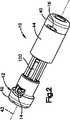
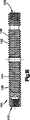
図1に例示されているように、本発明の装置10は、ここでは棘離隔装置と呼称されており、本体部12と、第1組の保持部材14、16と、第2組の保持部材18、20とを備えている。本体部12は、スリーブ44と、第1端部40と、第2端部42とを有している。第1端部40および第2端部42は、スリーブ44と相対的に移動することができる。しかしながら、本発明の多様な構成要素に対して多数の修正と代用が行えること、また、図で例示され説明されている実施形態は具体例にすぎないことを当業者なら認識するものと理解するべきである。 As illustrated in FIG. 1, the
装置10は、例えば、脊柱管狭窄症を治療する目的で、互いに隣接し合う椎骨28と椎骨30のそれぞれの棘突起の間に設置される。棘離隔装置10は1組の移植片10または複数の移植片10を含むキットから構成された単体部材であってもよいが、このような移植片は、複数の患者の互いに異なる解剖学的構造を考慮して多様な寸法を有している。装置10は本件では脊柱管狭窄症治療と関連して使用されるものと説明されているが、この装置は体内の別な部位に使用されてもよく、具体例としては、脊椎において脊椎各部の相互間の空隙を占有する場合が挙げられるが、椎骨での使用が望ましいことを、当業者なら容易に認識するだろう。従って、位置選定、外科手術処置、または、その両方をいかなる様式であれ限定するものと解釈するべきではない。 The
第1端部40、第2端部42、および、スリーブ44はどのような形状であってもよいが、例えば、丸型、楕円、多角形などが含まれる。更に、保持部材14、16、18、20は、椎体(例えば、棘突起)が1対の保持部材14と保持部材16の間、および、また別な1対の保持部材18と保持部材20の間に設置される限り、または、これら対を成す保持部材によって保持される限り、真直ぐ、凹状、凸状、或いは、それ以外の形状であってもよい。本体部12は、第1端部40、第2端部42、および、スリーブ44のほかに、保持部材14、16、18、20、または、これらの各種組合せを含んでおり、何であれ好適な素材から作成されているとよいが、この素材は生体適合性素材であるのが好ましく、具体例としては、金属(例えば、ステンレス鋼、チタン、アルミニウム、2種類以上の金属の合金)、可塑材、重合体、ラバー、セラミック、天然体組織(例えば、骨など)、または、複合材(すなわち、2種類以上の素材から作成される)などが挙げられる。装置10の構成要素を作成するために利用される素材を決定する場合には、多様な要因が考慮されることになるが、例えば、殺菌耐性、そこに加えられる力に対する耐性、重量耐性、耐久性、装置10を把持する能力のうちでも、特に、ラテックス製手袋を使用して把持する能力などが含まれるが、これらに限定されない。保持部材14、16、18、20に関して、保持部材14、16、18、20の弾性的かつ可塑的な屈曲性、変形自在性、または、その両方の他にも、変形後の形状維持能力も上述の要因に含まれることがある。装置10の本体部12、これ以外の構成部材、または、その両方が放射線透過性であってもよいし、放射線不透過性であってもよい。本体部12またはそれ以外の各種構成部材が放射線透過性である実施形態では、放射線不透過性マーカー(図示せず)は、本体部12またはそれ以外の各種構成部材に組み込まれてもよいし、または、取付けられてもよい。放射線不透過性マーカーは、患者の解剖学的構造に対して本体部12、または、それ以外の各種構成部材を医者が適切に整列させるのを支援することができる。 The
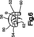
保持部材14、16、18、20は互いに類似した寸法および形状に設定することができ、更に、スリーブ44、第1部分40、および、第2部分42の中に通され、または、これらの下を通過する。図4から図6に例示されているように、保持部材14、16、18、20は各々が、例えば、ワイヤ50のような細長い構造体である。ワイヤ50はゲージが、約0.254mm(約0.01インチ)と約2.54mm(約0.1インチ)の間である。更に、ワイヤ50は、保持部材14、16、18、20に形成される前の長さが、約25.4mm(約1.0インチ)から約254mm(約10インチ)の間である。ワイヤ50は略U字型で、湾曲部56とアーム52、54が設けられており、アームは湾曲部56から伸び出している。湾曲部56は、図4、図5、および、図6に例示されているように、2平面以上の平面で湾曲または屈曲している。図4に例示されているように、湾曲部56の曲率半径R1は、例えば、約2.54mm(約0.1インチ)から約25.4mm(約1.0インチ)の間であり、約2.54mm(約0.1インチ)から約12.7mm(約0.5インチ)の間であるのがより好ましく、約3.81mm(約0.15インチ)から約5.08mm(約0.2インチ)の間であるのが最も好ましい。図5に例示されているように、湾曲部56の曲率半径は、例えば、約0.254mm(約0.01インチ)から約25.4mm(約1.0インチ)の間であり、約1.27mm(約0.05インチ)から約12.7mm(約0.5インチ)の間であるのがより好ましく、約1.27mm(約0.05インチ)から約2.54mm(約0.1インチ)の間であるのが最も好ましい。 The retaining
更に、図4および図6に例示されているように、アーム52の端部60はアーム52に対して第1の方向に角度θ(例えば、約90度)で屈曲しているとよい。アーム54の端部62は第2の方向に屈曲しているとよいが、第2の方向は第1の方向と同じ方向でも異なる方向でもよく、アーム54に対して角度α(例えば、約90度)を成しているとよい。一実施形態では、端部62はアーム52に向かって角度θ(例えば、約15度)で屈曲していてもよい(図6を参照のこと)。端部60と端部62は、アーム50、52に対して約90度とはそれぞれに異なる角度で屈曲していてもよいし、または、全く屈曲していなくてもよい。保持部材14、18は各々が、その端部60、62が端部42に作動可能に接続されており、保持部材16、20は各々が、その端部60、62が端部40に作動可能に接続されている。更に、保持部材14、16、18、20は各々が、その湾曲部56が端部40、42と滑動自在に関与し、これら端部によって維持され、これら端部によって案内され、または、これら端部に接続されている。 Furthermore, as illustrated in FIGS. 4 and 6, the
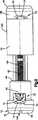
図7および図8に例示されているように、第1端部40は端部キャップ64と内側部66を備えており、その各々は形状が略円筒状であり、また、その両方が軸線43を中心としている。内側部66の端部68が端部キャップ64の内側の溝69に受け入れられた結果、内側部66と端部キャップ64は一緒に接続される。端部68は形状が円錐状であるが、端部68が端部キャップ64に保持される限り、円錐状以外の形状も採用することができることを当業者なら認識するだろう。 As illustrated in FIGS. 7 and 8, the
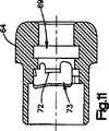
図10および図11に例示されているように、端部キャップ64には第1カム面および第2カム面が設けられており、第1の歯72および第2の歯72はカム面70に近接した位置にくる。カム面70の傾斜角度βは、例えば、約90度から約160度の間であり、約100度から約135度の間であるのがより好ましく、約105度から約115度の間であるのが最も好ましい。歯72およびカム面70は端部キャップ64の正反対位置で互いに対向する開口部73の内側に配置される。 As illustrated in FIGS. 10 and 11, the
更に、図12、図13、および、図14に例示されているように、内側部分66には第1上位スロット76および第2上位スロット78がそれぞれ設けられている。第1上位スロット76の端部の切欠き80はスロット76に対して、例えば約90度の角度λを成して(例えば、下向きの角度で)延びており、第2上位スロット78の端部の切欠き82はスロット78に対して、例えば約15度の角度μを成して(例えば、上向きで、尚且つ、第1上位スロット76に向かう角度で)延びている。切欠き80のスロット76に対する角度は、保持部材14、16、18、20の端部60の角度θと一致している。切欠き82のスロット78に対する角度は、保持部材14、16、18、20の端部62の角度θと一致している。内側部分66には第1下位スロット84および第2下位スロット86も設けられており、これらのスロットには切欠き88および切欠き90がそれぞれ設けられている。第1下位スロット84の端部の切欠き88はスロット84に対して、例えば約15度の角度σを成して(例えば、切欠き88は下向きに角度付けされて第2下位スロット86から離れる方に向かって)延びており、第2下位スロット86の端部の切欠き90はスロット86に対して、例えば約90度の角度ρを成して(例えば、上向きの角度で)延びている。切欠き88のスロット84に対する角度は保持部材14、16、18、20の端部62の角度θと一致している。切欠き90のスロット86に対する角度は保持部材14、16、18、20の端部60の角度θと一致している。 Furthermore, as illustrated in FIGS. 12, 13, and 14, the
図15および図16に例示されているように、保持部材14、16は、配備位置または未配備位置に置かれた時に、それぞれの少なくとも一部が互いの傍で、尚且つ、概ね本体部12の内側に設置される。図16に例示されているように、保持部材14、16のアーム52、54は、第1端部40の内側部分66の第1上位スロット76および第2上位スロット78に受け入れられる。保持部材14の端部60および端部62(図17)が第1端部40の第1上位スロット76の端部の切欠き80および第2上位スロット78の端部の切欠き82にそれぞれに受け入れられた結果、保持部材14は第1端部40に関して固定される。保持部材16の湾曲部56は第1端部40の端部キャップ64のカム面70(図7)に隣接して設置され、尚且つ、歯72を取り巻く位置に設置された結果、保持部材16は第1端部40の端部キャップ64に相関的に滑動することができるようになる。保持部材14、16のアーム52、54は第2端部42の内側部分66の第1上位スロット76および第2上位スロット78に受け入れられる。保持部材16の端部60、62が第2端部42の第1上位スロット76の端部の切欠き80および第2上位スロット78の端部の切欠き82にそれぞれに受け入れられた結果、保持部材16は第2端部42に相関的に固定される。保持部材14の湾曲部56が第2端部42の端部キャップ64のカム面70に隣接して設置され、尚且つ、歯72を取り巻いて設置された結果、保持部材14は第2端部42の端部キャップ64に相関的に滑動することができるようになる。 As illustrated in FIGS. 15 and 16, the retaining
同様に、保持部材18、20は、配備位置または未配備位置に置かれた時に、それぞれの少なくとも一部が互いの傍で、尚且つ、概ね本体部12の内側に設置される。図16に例示されているように、保持部材18、20のアーム52、54は、第1端部40の内側部分66の第1上位スロット84および第2上位スロット86に受け入れられる。保持部材18の端部60および端部62(図17)が第1端部40の第1上位スロット86の端部の切欠き90および第2上位スロット84の端部の切欠き88にそれぞれに受け入れられた結果、保持部材18は第1端部40に関して固定される。保持部材20の湾曲部56は第1端部40の端部キャップ64のカム面70(図7)に隣接して設置され、尚且つ、歯72を取り巻く位置に設置された結果、保持部材20は第1端部40の端部キャップ64に相関的に滑動することができるようになる。保持部材18、20のアーム52、54は第2端部42の内側部分66の第1上位スロット86および第2上位スロット84に受け入れられる。保持部材16の端部60、62が第2端部42の第1上位スロット86の端部の切欠き90および第2上位スロット84の端部の切欠き88にそれぞれに受け入れられた結果、保持部材20は第2端部42に相関的に固定される。保持部材18の湾曲部56が第2端部42の端部キャップ64のカム面70に隣接して設置され、尚且つ、歯72を取り巻いて設置された結果、保持部材18は第2端部42の端部キャップ64に相関的に滑動することができるようになる。 Similarly, when the holding
図7から図9に例示されているように、第2端部42の端部キャップ64および内側部分66は第1端部40の端部キャップ64および内側部分66と同一である。本体部12の内側では、保持部材14、16は概ね互いの傍らに設置される。保持部材14、16のアーム52、54は内側部分66の第1上位スロット76および第2上位スロット78に受け入れられる。保持部材16の端部60および端部62(図17)は第1上位スロット76の端部の切欠き80および第2上位スロット78の端部の切欠き82のそれぞれに受け入れられる。保持部材14の湾曲部56は端部キャップ64のカム面70(図8)に隣接して設置され、尚且つ、歯72を取り巻いて設置される。同様に、保持部材18、20は概ね互いの傍で本体部12の中に設置される。保持部材18、12のアーム52、54は内側部分66の第1下位スロット84および第2下位スロット86に受け入れられる。保持部材20の端部60および端部62は、第1下位スロット86の端部の切欠き90および第2下位スロット84の端部の切欠き88にそれぞれに受け入れられる。保持部材18の湾曲部56は端部キャップ64のカム面70に隣接して設置され、尚且つ、歯72を取り巻いて設置される。 As illustrated in FIGS. 7 to 9, the
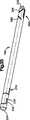
コネクタ100は本体部12の端部40と端部42の間で軸線43に沿って延びている。図18に例示されているように、コネクタ100には外側ねじ部が設けられているとともに、区分102および区分104が設けられている。区分102および区分104は各々に作動器具(例えば、図36の作動器具184)を受け入れる陥凹部105が設けられている。陥凹部105には把持面が設けられており、これは作動器具の対応する把持面に係合する(例えば、陥凹部105は形状が多角形である)。区分102にはねじ部106が、また、区分104にはねじ部108がそれぞれに設けられており、これらねじ部はコネクタ100の周囲で互いに反対の向きに延びている(例えば、区分102には右手ネジ106が設けられており、区分104には左手ネジ108が設けられている)。図7および図9に例示されているように、コネクタ100のねじ部106、108は本体部12の端部40、42の内側部分66の対応する内側ねじ部114とねじ結合する。このような構成により、内側部分66に相関的にコネクタ100を回転させると、端部40、42はコネクタ100に沿って軸線方向に互いに向かう方向に移動し、または、互いから離れる方向に移動する。 The
2つの端部40、42が軸線方向に互いに向かって移動すると、保持部材14、16、18、20が端部40、42に関して移動する。保持部材14、16、18、20は、それぞれの端部60、62の取付け先である端部キャップ64および内側部分66と一緒に移動する。端部40が移動すると、第1端部40の端部キャップ64に固定されている保持部材14、18も移動し、保持部材14、18の湾曲部56は第2端部42の端部キャップ64のカム面70に強く押し当てられる。同様に、端部42が移動すると、第2端部42の端部キャップ64に固定されている保持部材16、20も移動し、保持部材16、20の湾曲部56は第1端部42の端部キャップ64のカム面70に強く押し当てられる。カム面70が湾曲部56を案内するため、保持部材16、20は第1端部40の端部キャップ64に設けられた開口部73を通って外へ移動し、保持部材14、18は第2端部42の端部キャップ64に設けられた開口部73を通って外へ移動する。より詳細に説明すると、本体構造部12の端部40および端部42が引き続き軸線方向に互いに向かって移動すると、保持部材ワイヤ50のアーム52、54も開口部73を通って外へ移動する。アーム52およびアーム54がカム面70を押圧して外方向に滑動すると、アーム52、54は偏向される(例えば、弧状経路または真直ぐな経路に沿って)。保持部材14、16、18、20は予め屈曲しているため、端部40、42から外へ張り出してしまえば、屈曲形状を取り戻すことができるようになっている(例えば、保持部材14、16、18、20は形状記憶特性を有している)。これに代わる例として、保持部材14、16、18、20は、本体部12から外へ移動すると変形される(弾性により、または、可塑性により)。保持部材14、16、18、20は、端部40、42から外へ張り出すと、配備位置で棘突起の周囲に隣接して配置され、斯くして図1に例示されているように、保持部材14、16、18、20は、装置を適所に保持し、すなわち、互いに隣接し合う棘突起の間に装置を維持するのを助けることができる。配備位置では、保持部材14、16、18、20は長さL1(図1)だけ本体部から離れて張り出すが、この長さL1は、例えば、約5.08mm(約0.2インチ)から約50.8mm(2.0インチ)の間であり、約7.62mm(約0.3インチ)から約25.4mm(1.0インチ)の間であるのがより好ましく、約10.16mm(約0.4インチ)から約15.24mm(約0.6インチ)の間であるのが最も好ましい。更に、配備位置では、保持部材14、16、18、20は互いに隣接し合う保持部材14と16、および、保持部材18と20の間の寸法がD2(図1)であり、この寸法はスリーブ44(図19)の長さL2と実質的に同一である。寸法D2は、例えば、短くとも約2.54mm(約0.1インチ)から約50.8mm(2.0インチ)の間であり、約5.08mm(約0.2インチ)から約25.4mm(1.0インチ)の間であるのがより好ましく、約10.16mm(約0.4インチ)から約12.7mm(約0.5インチ)の間であるのが最も好ましい。更に、保持部材14、16、18、20は本体部12の中まで後退することができる。 As the two ends 40, 42 move toward each other in the axial direction, the holding
スリーブ44は、図1に例示されているように、互いに隣接し合う棘突起の間の適所に本体部12を保持するのを助けることもできる。図2の伸張形状では、スリーブ44は移植片の残りの各部(例えば、端部40、42および保持部材14、16、18、20)に相関的に軸線方向および回転方向に自由に移動することができる。図3の収縮形状では、スリーブ44は端部40と端部42の間に捕獲され、軸線43を中心として軸線方向に移動するのを阻止される。一実施形態では、スリーブ44はコネクタ100に関して固定されているため、スリーブ44はコネクタ100に相関的に軸線方向に移動することができないようになっている。しかし、スリーブ44は、端部40、42ばかりか保持部材14、16、18、20に対しても同様に相関的に、自由に回転することができる。棘の屈曲、または、それ以外の運動のせいで棘突起24、26がスリーブ44に回転力を付与した場合、そのような力は移植片10の残りの部分に相関的にスリーブ44を回転させることにより散逸させることができる。このような構成により、スリーブ44から保持部材14、16、18、20に回転力を伝達するのが阻止されることで、保持部材14、16、18、20が不所望な回転をするのを防ぎ、これら保持部材が変位するのを防ぎ、または、その両方を阻止するのを助けることができるようになる。 The
図19に例示されているようにスリーブ44はその外側面120の直径がDであり、この直径はスリーブの長尺に沿って均一である(例えば、スリーブの外形は円筒状である)。例えば、この直径は約2.54mm(約0.1インチ)から約25.4mm(約1.0インチ)の間であり、約3.81mm(約0.15インチ)から約20.32mm(約0.8インチ)の間であるのがより好ましく、約5.969mm(約0.235インチ)から約16.002mm(約0.63インチ)の間であるのが最も好ましい。スリーブの厚さTは、例えば、約0.254mm(約0.01インチ)から約3.81mm(約0.15インチ)の間であり、約0.508mm(約0.02インチ)から約1.778mm(約0.07インチ)の間であるのがより好ましく、約0.889mm(約0.035)インチから約1.27mm(約0.05インチ)の間であるのが最も好ましい。図8に例示されているように、端部40、42の端部キャップ64の直径は、直径Dと実質的に同じ長さである。スリーブ44の内側面122の外形(例えば、凹状の輪郭)は放射方向外向きに湾曲しているとよい。内側面122はスリーブ44の先細り中間部124を画定しており、この中間部はスリーブ44の両端の部分126に比べて厚みが小さくなっている。このような構成はスリーブ44の中間部126の可撓性を高めることができるため、スリーブ44は、棘突起24、26から力が付与されると、放射方向内向きに偏向させることができるようになる。 As illustrated in FIG. 19, the
実施形態によってはスリーブ44が不必要となる場合があることに、注目するべきである。例えば、図7Aおよび図7Bに例示されているように、第1端部40には張出し壁部40aが設けられている。移植片が収縮形状になると、張出し壁部40aは互いに隣接し合う棘突起の間に設置される。代替の実施形態では、図7Cおよび図7Dに例示されているように、第1端部40および第2端部42には張出し壁部40a、40bがそれぞれ設けられている。移植片が収縮形状になると、張出し壁部40a、42aは互いに隣接し合う棘突起の間に設置することができるようになる。 It should be noted that in some embodiments, the
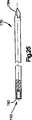
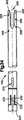
使用に際し、本体部12は互いに隣接し合う椎骨28、30(図1に概略的に例示されている)の棘突起24と棘突起26の間の空間23に挿入される。本体部12は、図2に例示されているような、第1の伸張形状を呈している。このような形状の時、本体部12の長さL(図7)は、例えば、約3.81mm(約0.15インチ)から約127mm(約5.0インチ)の間であり、約12.7mm(約0.5インチ)から約50.8mm(約2.0インチの間であるのがより好ましく、約30.48mm(約1.2インチ)から約35.56mm(約1.4インチ)の間であるのが最も好ましい。第1の伸張形状では、本体部12の端部40、42は長手方向軸線の方向の中心軸線43に沿って互いから離隔されている。スリーブ44は端部40と端部42の間に位置している。この伸張形状では、保持部材14、16、18、20は、後退位置すなわち未配備位置に設置されているため、概ね本体部12の内側に位置している。このような構成により、本体部は脊椎の側面から棘突起24と棘突起26の間に挿入することができる(例えば、横挿入)。棘離隔装置10が棘突起24と棘突起26の間に設置されてしまうと、本体部12は、図3に例示されているような第2の収縮形状まで移動させられる。これを達成するために、端部40、42が軸線方向に互いに向けて移動させられる。収縮形状では、本体部12の長さL(図7)は、例えば、約1.27mm(約0.05インチ)から約50.8mm(約2.0インチ)の間であり、約12.7mm(約0.5インチ)から約38.1mm(約1.5インチ)の間であるのがより好ましく、約17.78mm(約0.7インチ)から約22.86mm(約0.9インチ)の間であるのが最も好ましい。端部40および端部42が互いに向かって移動すると、保持部材14、16、18、20は後退位置から図3の配備位置へ本体部12から外に移動させられる。配備位置では、保持部材14、16は本体部12から外に張出し、尚且つ、椎骨28の棘突起24の両側に位置する。保持部材18、20は本体部12から外に張出し、尚且つ、椎骨30の棘突起26の両側に位置する。このように配置すると、本体部12は互いに隣接し合う棘突起24と棘突起26の間に所望の空隙を維持するのを助けるよう機能する。更に、保持部材14、16、18、20は脊椎、その周囲の柔組織、または、その両方に関して本体部12を適所に保持するのを助けるよう機能する。 In use, the
例えば、移植片ホルダー140、ガイドワイヤ170、拡張器176、挿入管180、182、作動器具184、取出し器具290などのような多様な器具を使って、移植片10を挿入し、取出し、または、その両方を実施することができる。以下で説明する各種器具は移植片10と併用することができるが、本件に記載されている器具の代用として各種器具をどれだけ利用してもよいことを当業者なら容易に認識するだろう。 For example, the
図22から図24の移植片ホルダー140は細長い茎状部142およびハンドル144を備えている。細長い茎状部142は中空で(例えば、管状で)、ハンドル144から伸張し、遠位端143が設けられている。操舵輪148がハンドル144に設置されている。シャフト146は、中空であってもよいが、茎状部142の中を通って延びており、尚且つ、操舵輪148に作動可能に接続されているため、操舵輪148を回転させた結果として、茎状部142に相対的にシャフト146を回転させることができる。図24に例示されているように、シャフト146の遠位端143は茎状部142の開放端150から突出しており、更に、ねじ部152が設けられている。1対の突出部154は、互いに正反対位置で対向しており(一方のみが図14に例示されている)、シャフト146の近位で茎状部142の開放端150から軸線方向外向きに突出している。或る実施形態では、1個以上の突出部154が採用されている。 The
移植片ホルダー140は第1端部40または第2端部42に係合し、挿入器具として使用されて、移植片10を脊椎の側面から据付け位置の中へ移動させることができるようになっている。図20および図21に例示されているように、第1端部40、第2端部42、または、これら両端部40、42の端部キャップ64には外側端部132に1対のスロット130が設けられている。しかしながら、端部40、42には1個以上のスロット130が設けられており、これらスロットが茎状部142の1個以上の突出部154と嵌合することに注目するべきである。更に、第1端部40、第2端部42、または、これら両端部40、42には内側ねじ部134が設けられており、ねじ部は外側端部132から軸線方向内側寄りに延びている。シャフト146のねじ部152は第1端部40または第2端部42のねじ部134にねじ結合する。その後、操舵輪148を回転させることでホルダー140を引き出し、その結果として、ホルダー140の突出部(1個または複数個)154を第1端部40または第2端部42に向けて引き寄せることになるため、突出部(1個または複数個)154は第1端部40または第2端部42のスロット130(1個または複数個)の中に挿入される。端部40、42およびホルダー140をこのように構成することにより、端部40、42および保持部材14、16、18、20が軸線43を中心としてホルダー140に相関的に回転することを阻止することができる。 The
棘離隔装置10は、例えば、脊椎への横挿入アプローチを利用することで、本体部に挿入することができる。患者の体側に切開部が設けられる。図25に例示されているようなガイドワイヤ170が切開部を通して挿入される。ガイドワイヤ170の遠位端194は先鋭にされて、柔組織を刺し通すのに役立つようにしている。ガイドワイヤ170の近位端190には、例えば、端ぐり機で設けた穴の内側にねじ部を切ったカウンターボア192などのような、ねじ嵌合部が設けられている。医者はガイドワイヤ170を直接的に把持するようにしてもよいし、または、ホルダー172を使ってガイドワイヤ170を保持するようにしてもよい。ホルダー172はハンドル172、通路195、および、ネジ196のような締め部材であって、通路195と交差するものを備えている。ガイドワイヤ170は、ネジ196を締めることにより、通路195の適所で固定することができる。ガイドワイヤ170は、本体部に挿入される前または本体部に挿入された後で、ホルダー172に取付けられる。大抵の場合、ガイドワイヤ170は、互いに隣接し合う棘突起24と棘突起26の間の空隙23の中までガイドワイヤ170の遠位端194を医者が伸張させるのに十分な長さを有している。しかしながら、場合によっては、医者は、延長部174を使って、ガイドワイヤ170の長さを伸ばすことが必要となることがある。 The
延長部174は、遠位端200および近位端202が設けられている細長い部材(例えば、ロッドまたはバー)であってもよい。遠位端204にはねじ嵌合部204が設けられており、ねじ嵌合部はねじ部の形態を呈している。遠位端204は、延長部174の残余の部分と比較して、直径が減じられている。延長部174のねじ嵌合部204はガイドワイヤ170の近位部190に設けられたカウンターボア192の中にねじ込まれる。 The
ガイドワイヤ170が体内の適所に置かれた後で、拡張器176はガイドワイヤ170、延長部174(使用されている場合のみ)、または、その両方に被せて設置され、更に、ガイドワイヤ170、延長部174、または、その両方に沿って拡張器176を滑動させることにより、脊椎に向けて移動させられる。図28に例示されているように、拡張器176は中空の管状構造体であり、その中を通路205が通っている。拡張器176の遠位端208には先細り面206が設けられている。拡張器176の先細り面206が棘突起22と棘突起24の間の空隙23に向けて移動させ、更にその中にまで移動させると、先細り端206が柔組織を拡張させることができるようになる。ピン210が近位端212の付近の通路205の中まで延びて入る。図29に例示されているように、拡張器176はガイドワイヤ170、延長部174、または、その両方に被せるように設置されて、ピン210がガイドワイヤ170の近位端190に係合するまで、延長部174の近位端202に係合するまで、または、その両方に係合するまで移動させられる。拡張器176の長さはガイドワイヤ170の長さと相関関係があるため、先細り面206が棘突起24と棘突起26の間の空隙23に到達した後は、拡張器176に設けられたピン210がガイドワイヤ170の近位端190に当接して、拡張器176が移動するのを阻止する。1個以上の連続する拡張器が拡張器176に被せて設置されたうえで使用され、皮膚から椎骨まで組織を貫く開口部を拡張することができるようにしている点に注目するべきである。 After
拡張器176が体内に設置された後で、管材180および管材182は拡張器176に被せて設置される。管材180および管材182は、寸法(例えば、直径、面積、または、その両方)が互いに異なる1組の管材の一部であって、多様な患者の解剖学的構造に適合するように図ってもよい。例えば、管材の直径、面積、または、その両方は約2.54mm(約0.1インチ)から約25.4mm(約1.0インチの間であり、約3.81mm(約0.15インチ)から約20.32mm(約0.8インチ)の間であるのがより好ましく、約6.35mm(約0.25インチ)から約16.51mm(約0.65インチの間であるのが最も好ましい。管材は、組織を離隔するばかりか、互いに隣接し合う椎骨の棘突起と棘突起の間の空隙を伸延させるためにも利用される。図30から図32の管材180は形状が図33から図35の管材182に類似している。管材180は管材182よりも直径が小さく、短い。1組の管材のうちの全部の管材が、管材180、182も含めて、円筒状であり、直径の大きい管材がその次に直径が大きい管材の上に被せてぴったり合う寸法に設定されている。このようにして、1組の管材は全部が同心状態で一緒に入れ子にすることができる。これに加えて、幾つもの管材が多様な寸法の装置10に対応している。このような管材の形状は、管材の内径が棘離隔装置10の外径Dに緊密に一致するように設定されている。管材をこのような形状にすることにより、棘離隔装置10が図2の伸張形状になった時にも、装置10が対応する管の中を密着しながらもスムーズに滑動することができるようになる。管材には2個のスロット260も設けられており、これらのスロットにより後段で説明するように保持部材14、16、18、20を管材の中に配備することができるようにしている。他の実施形態では、管材には1個のスロット260が設けられている。 After the
使用にあたり、医者はまず、例えば図30に例示されている管材180などのような、第1寸法D1の管材を選択する。他の管材と同様に、管材180には先細り遠位端220が設けられている。医者はガイドワイヤ170、拡張器176、または、これらの両方(すなわち、図29の組立体:アセンブリ)の上に被せて管材180を移動させ、管材180を拡張器176に沿ってその遠位端208に向けて動かす。管材180の先細り遠位部220は、棘突起24と棘突起26の間の空隙23の中まで移動すると、柔組織を拡張させるばかりか、棘突起24、26を互いに離隔することができるようになる。更に、或る管材の上に次に大きい寸法の管材を連続して被せて移動させることにより、拡張と伸延(離隔)を達成することができる。このようなプロセスは、例えば図33の管材182のような最後の最外殻管材によって拡張と伸延(離隔)が完了するまで繰り返される(すなわち、互いに隣接し合う棘突起が所望の距離だけ分離されるまで、拡張と伸延(離隔)が継続する)。互いに隣接し合う椎骨と椎骨の間に管材を適切に設置するのを支援するために、管材には少なくとも1対の表示スロット266が設けられている。表示スロット266は軸線方向に管材の遠位端262から離隔され、互いに正反対位置で対向する。表示スロット262は、図30および図33に例示されている図面位置から管材180、182を観た場合は互いに重なり合っており、互いに関して或る角度に配向されている。例えば、図30または図33に例示されている配向の管材を観た場合は、表示スロット266は互いに90度を成しているため、それぞれが重なり合うX線画像はXの文字を形成する。このような構成を利用することにより、X線で視認する際に各種形状を生成することができる。図30および図33の実施形態に例示されているように、管材180、182のスロット266より近位にまた別な対の表示スロット268を設けてもよい。これら対を成した表示スロット266、268により、医者は、脊柱の背面から見たX線図にX字型の画像が形成されるまで管材を回転させるとよい。X字型画像が見えるようになると、管材、とりわけ、スロット266が正確に配向されて、その中に保持部材14、16、18、20が配備される準備ができたことが分かる。 In use, the physician first selects a tubing of a first dimension D1, such as
図33で分かるように、管材には各々の近位端224にノブ222が設けられており、このノブが管材を貫く通路の中で内側寄りに突出している。径の大きい管材がその次に大きい径の管材の上に被せて設置されると、大きい方の径の管材に設けられているノブ222が移動により小さい方の管材の最遠位端224と当接する。このような構成にすることにより、大きい方の管材が小さい方の管材の上に被さって移動するのを制限した結果、互いに同心の複数管材の先細り遠位端220が棘突起24と棘突起26の間の同じ位置で重なり合う。 As can be seen in FIG. 33, the tubing is provided with a
管材は各々の近位端224に1対のスロット230が設けられている。2本のスロット230は互いに対向し合う1対の部分232を線引き区分けしており、このような部分232は偏向させることができる。部分232は軸線方向にノブ222と整列させることができるが、ノブ222から軸線方向に短い距離だけ離隔されているとよい。小さい方の管材(例えば、管材180)を最外殻の管材182から取出すのに、医者はノブ222とは反対の位置224aに位置で(例えば、ノブから約180度の位置で)ノブ222に近づく方向に(例えば、最外殻の管材182の長手方向軸線に直交する方向に)近位端224を押すとよい。スロット230により、ノブ222および部分232を含む、管材182の近位端224を図30に例示されているように上向きに偏向させることができるようになり、その結果、内側にある互いに同心の複数の管材を全部一緒に最外殻の管材182から取出すことができる。ガイドワイヤ174および拡張器176も、最外殻の管材182から取出すことができる。管材182が棘突起24と棘突起26の間に設置された状態で、医者は最外殻管材182の内側寸法に一致する寸法の装置10を選択する。次に、医者は選択した装置10を移植片ホルダー140に取付けてから、管材182の中で装置10を棘突起24、26に向けて移動させ、両棘突起の間に入れる。移植片10の長手方向軸線が移植片ホルダー140の長手方向軸線と整列して一致するように、移植片10が移植片ホルダーに接続されているのが好ましい。 The tubing is provided with a pair of
最外殻管材の最近位部224がホルダー140の階段状部分250(図22および図23)に嵌合するまで、移植片ホルダー140が管材182の中に挿入される。階段状部分250の寸法は、段差の各々が1組の管材(例えば、管材180、182)のうちの1本の内側寸法に一致するように設定されている。階段状部分250の段差は各々に切欠き252が設けられており、対応する管材に設けられたノブ222を受け入れるようになっている。このような構成により、互いに隣接し合う棘突起24、26の間の適切な位置に移植片を設置するのは元より(すなわち、階段状部分250が制止部材として作用し、管材の中で装置10が遠過ぎる位置まで挿入されることがないようにするのは元より)、保持部材14、16、18、20をスロット260と整列させるのを(すなわち、切欠き252にノブ222を設置することで回転によって不整列になるのを阻止するのを)助けることができるようになる。 The
拡張器を挿入している間、拡張管材、挿入管材、または、その両方は、柔組織、傷組織、または、靭帯が原因で生じる実質的な抵抗に遭遇する。時には、ハンマーを使用してでも、これらの器具の挿入を制御することができるようにすることが必要になることがある。各種器具を挿入することに対する抵抗により、これらの器具の外径が小さすぎて医者の手で適切に握ることができない場合には、体内に器具を挿入するのが一層困難になる。図35Aに例示されているように、ハンドル600を使って握り面を向上させて、例えば、
拡張器176および管材180、182を挿入することができる。これに加えて、ハンドルにハンマーで打つ面を設けて、器具に損傷を生じることなく、器具を体内に挿入するようにしてもよい。ハンドル600またはその各部は、例えば、重合体、金属、または、セラミックから作成することができる。While inserting the dilator, the expansion tubing, insertion tubing, or both encounter substantial resistance caused by soft tissue, wound tissue, or ligaments. Sometimes it may be necessary to be able to control the insertion of these instruments even using a hammer. Resistance to inserting various instruments makes it more difficult to insert instruments into the body if the outer diameter of these instruments is too small to be properly grasped by the physician's hand. As illustrated in FIG. 35A, the
A
ハンドル600の形状は、多様な寸法の各種器具にハンドル600が適合するように設定される。例えば、ハンドル600は、約8 mmから約18 mmの間の面積または直径の各種器具に係合するように設計されていてもよい。ハンドル600には人間工学的に成形された本体部601と多様な寸法の器具を把持する係合機構とが設けられている。係合機構は平行な鉗子に類似していてもよい。図35Bおよび図35Cに例示されているように、係合機構は複数の突起部602を有しており、これらが器具の外側面に係合して器具を把持するようにしてもよい。少なくとも1本の突起部602に1本以上の畝状部604が設けられており、器具に係合するようにしてもよい。ハンドル600が管材180、182と併用される実施形態では、畝状部604は管材180、182の1本以上のスロット270に嵌合する。畝状部604がスロット270に嵌合することにより、管材180、182は軸線を中心として回転運動するのが阻止され、また、軸線に直交する方向に直線運動(すなわち、管材の軸線から離れる方向に直線運動する)のも阻止される。 The shape of the
ノブ610の運動により、複数の突起部602は互いに相関運動する(例えば、互いに向かって移動するか、または、互いから離れる方向に移動する)。ノブ610はキャップ620とロック機構630を有しており、これらにはねじ部が切られている。キャップ620は、医者がハンマーを使ってキャップ620に衝撃を加えるような設計になっているとよい。例えば、キャップ620は、ハンマー打ちの衝撃時のピーク荷重を低減することができる素材(例えば、重合体、金属、セラミックなど)から作成されているとよい。キャップ620がハンドル600の軸線Aに沿って移動することで、突起部602を互いに相対運動させることができる。キャップ620は、遠位端603に向かって前方に押されると開き、それにより、本体部601の中に器具を挿入することができるようになっている。突起部602はバネが装填されて、キャップ620を緩めると突起部602閉じるようになっていることにより、器具(例えば、管材180、182)と係合する。突起部602が思いがけず開いたり、器具から離脱したり、または、その両方が起こるのを回避するために、ロック機構630はハンドル600の本体部601に係合するまで回転させられる。突起部602を移動させてロックする上記以外の手段も想起されることが分かる。更に、ハンドル600を脊椎器具と併用するという文脈で説明してきたが、ハンドル600の寸法および形状は上記以外の各種器具と係合して、体内、または、体表のどこでも別な部位に各種処置を施すように設定されていてもよい。 The movement of the
装置10およびホルダー140が適所(すなわち、管材182の遠位端220)に置かれると、図36に例示されているような作動器具184(例えば、ネジ回し)がホルダー140の中空シャフト146の中に挿入される。これに代わる例として、ホルダー140、作動器具184、および、装置10は、体内への設置前に全部一緒に組付けられてから単体として体内に挿入されるとよい。作動器具184の係合部254がコネクタ100の陥凹部105に受け入れられてしまうまで、器具184はホルダー140の中に挿入される。次いで、ホルダー140が適所に保持されている状態で、器具184を回転させる。器具184によりコネクタ100が回転させられるが、ホルダー140が端部40、42が回転運動するのを阻止する。このようにして、端部40、42は軸線43に沿って互いに向かって軸線方向に移動する。端部40、42が互いに向けて移動すると、保持部材14、16、18、20が本体部12から外へ出て配備され、互いに隣接し合う棘突起24、26を取り巻いて設置される。保持部材14、16、18、20が棘突起をきつく把持するまで、または、棘突起に堅固に係合するまで、端部40、42を互いに向けて移動させることにより、装置10を適所に保持することができる点に注目するべきである。保持部材14、16、18、20が完全に配備位置に設置された時の端部40から端部42までの距離は、保持部材14、16、18、20の少なくとも一部が棘突起に係合した時のこれら保持部材の長さL1で決まる。保持部材14、16、18、20の長さL1は、棘突起の幅W(図1)で決まる。 When the
保持部材14、16、18、20は管材のスロット260を通って本体部12から外に出て配備される。スロット260は管材の各々の最遠位端262から近位端224に向けて軸線方向に延びている。スロット260は互いに正反対位置で対向しており、それらの形状は、保持部材14、16、18、20が棘突起を取り巻いて配備された後で、管材182が装置10の上に被さって移動するように(例えば、装置10の一部に被さり一部を露出させた状態で滑動するように)設定されている。管材の近位端224の付近の1対のスロット270は覗き窓として機能し、これにより、操作者はスロット260を(延いては、保持部材14、16、18、20を)頭尾方向に整列させることができるようになる。 The retaining
保持部材14、16、18、20が配備されて装置10が適所に置かれた状態で、器具184がホルダーから引き出される。ホルダー140は操舵輪148を回転させることにより装置から切り離される。その後、ホルダー140が管材182から引き出される。次に、管材182は患者から取出され、装置10を互いに隣接し合う棘突起24と棘突起26の間に残存させる。 With the retaining
図37に例示されているように、取出し器具290を使って保持部材14、16、18、20を本体部12の中に後退させ、本体部から装置10を取出すことができる。取出し器具280は、近位端292と2つの別個の係合部294、296が設けられている細長い部材(例えば、ロッド)である。近位部292の寸法と形状は、ハンドル、ドリル、または、これ以外の、回転運動を付与することができる何か別な装置と係合するように設定されている。第1の係合部296にはねじ部298が切られており、器具290を端部64の開放外側端132(図21)に挿入することができるようになっている。第2の係合部294の寸法および形状は(例えば、多角形または六角形でもよい)コネクタ100の陥凹部105(図18)に係合するように設定されている。 As illustrated in FIG. 37, the
脊椎から棘離隔装置10を除去するために、医者は脊椎への横挿入アプローチを採用する。患者の体側に切開部が設けられ、器具290の第2係合部294が陥凹部105に挿入されるまで、器具290を体内に挿入する。器具290はガイドワイヤ170、延長部174、または、その両方の適所で使用される。拡張器176は器具290の上を伝って挿入される。小さい管材から順に、管材180、182などの管材が拡張器176に被せて挿入され、互いに隣接し合う棘突起24と棘突起26の間の空隙23に入れられる。最外殻の管材182を設置することにより拡張と伸延(離隔)が完了すると、管材、拡張器176、または、その両方が管材182から取出される。 To remove the
次に、器具290およびコネクタ100が回転させられて、本体部12の端部40、42を互いから軸線方向に離れる方向に駆動する。本体部12が図3の収縮形状から図2の伸張形状まで移動すると、保持部材14、16、18、20が配備位置から後退位置まで本体部の中に引き戻される。端部42がコネクタ100の隣接する端部に向けて軸線方向に移動すると、第1係合部296のネジ298が端部42の内側部分66の内側ネジ114(図7および図9)にねじ結合する。このような構成により、器具290は移植片ホルダー140の取付けによく似た態様で装置10に係合させられる。次に、ロッド290を使って、管材182を通して棘離隔装置10を引っ張ることができる。 Next, the
図38から図40は、脊柱管狭窄症を治療するための移植片のまた別な実施形態を例示している。装置300は、多様な解剖学的構造に適合する多様な寸法の1組の移植片の一部である。本体部302は、上述の据付装置を使用することにより、1対の互いに隣接し合う棘突起24と棘突起26(図1)の間に据付を行うのに適した構成になっている。本体部302は第1端部304および第2端部306を有しており、長手方向軸線307に中心が置かれている。スリーブ308は本体部302の2つの端部304、306の間で軸線方向と回転方向に自由に移動することができる。 FIGS. 38 through 40 illustrate another embodiment of an implant for treating spinal stenosis. The
第1端部304はベース310を有しており、この部分は、概ね丸天井型である。茎状部312はベース310から軸線方向に突出している。茎状部312はどのような形状であってもよいが、例えば、円筒状である。第1蝶番部320は第1保持部材322をベース310に作動可能に接続することができる。蝶番部320は旋回軸線323を有しており、この軸線は本体部302の長手方向軸線307と直交している。第1蝶番320は、第1保持部材322が旋回または回転する際の中心となるピンを備えている。第2保持部材326は第2蝶番部328によって茎状部312に作動可能に接続されており、この蝶番部の旋回軸線329は第1の旋回軸線323と平行である。第2蝶番部328は、第2保持部材326が旋回または回転する際の中心となるピンを備えている。第3保持部材340は第3蝶番部344によって、また、第4保持部材342は第4蝶番部346によって、それぞれに、ベース310および茎状部312に作動可能に接続される。蝶番部344は軸線347を有しており、蝶番部346は軸線349を有しており、これら軸線は互いに平行である。 The
装置300は、装置10のコネクタ100に実質的に類似している内側コネクタ(図示せず)を有している。従って、移植片300のコネクタの2つの部分には反対方向のねじ部が切られており、これら2つの部分は各々が端部304および端部306とねじ結合する。軸線307を中心としたコネクタの回転の結果として、端部304、306が互いに向かって軸線方向に移動する。第1端部302に設けられた開口部350は作動器具(例えば、ネジ回し)の接近路となってコネクタに係合することができるようにすることで、本体部302は図38および図39の伸張形状から図40の収縮形状に移すことができる。
端部304、306が軸線方向に一緒に移動させられると、第1保持部材322および第3保持部材340はスリーブ308の面352に接触し、スリーブ308は移動するにつれて第1保持部材322と第3保持部材340を軸線307から離れる外向きに押す。更に、第2端部306が内向きに移動すると、第2保持部材326および第4保持部材342が移動し、すなわち、押されて、第2端部306の開口部355の内側に位置するカム面354を圧迫する。このようにして、保持部材326、342は軸線307から外向きに移動する。従って、保持部材322、326、340、342は後退位置から配備位置まで旋回運動し、これら保持部材は互いに隣接し合う棘突起24と棘突起26の両側に位置するようになる。スリーブ308は、図1に例示されているスリーブ44と同じ態様で、棘突起24、26から力が付与されると回転し、偏向し、または、その両方を行うことができるようになる。 When the
図41は、脊柱管狭窄症を治療するための装置の更に別の実施形態を例示している。装置400は本体部432、上位保持部材402、404、および、下位保持部材406、408を有している。本体部432は第1端部410、第2端部412、および、これら両端部の間に位置するスリーブ450を有している。上位保持部材402は第1端部410に設けられた蝶番部414によって、また、上位保持部材404は第2端部412に設けられた蝶番部416によって旋回自在に接続されている。蝶番部414の旋回軸線417と蝶番部416の旋回軸線419は互いに平行である。下位保持部材406は第1端部410に設けられた蝶番部424によって、下位保持部材408は第2端部412に設けられた蝶番426によって旋回自在に接続されている。蝶番部424の旋回軸線427と蝶番部426の旋回軸線429は互いに平行であるとともに、旋回軸線417、419にも平行である。4本の旋回軸線417、419、427、429の全部が本体部432の長軸中央軸線431に直交する。 FIG. 41 illustrates yet another embodiment of a device for treating spinal stenosis. The
選択された寸法の本体部432は、上述の据付装置を使って、互いに隣接し合う棘突起24と棘突起26(図1)の間に据付けることができる。作動器具(例えば、ネジ回し)は、適所に置かれた後で、第1端部410に設けられた接近用開口部440の中に挿入され、本体部432の内側でコネクタ(図示せず)を作動させる。2個の端部410、412を軸線方向に引き寄せるために、コネクタ100と同様に、図41のコネクタが回転させられる。伸張形状では、保持部材402、404、406、408が軸線431に実質的に平行に設置される。2個の端部410、412が引き寄せられると、保持部材402、404、406、408はスリーブ450の両端の面446を押圧するように移動させられる。図41に例示されているように、これにより、保持部材402、404、406、408は後退位置から配備位置まで旋回させられ、配備位置では、保持装置402、404、406、408は軸線431と本体部432から外向きに張り出す。収縮形状では、保持部材402、404、406.408は互いに隣接し合う棘突起24と棘突起26の間の空隙23の内側に配備され、そこに装置400を保持することができるようになる。更に、スリーブ450は、互いに隣接し合う棘突起24と棘突起26から力が付与されると、装置400の残余の部分(例えば、端部410、412)に相関的に回転し、偏向し、または、その両方を行うことができるようになる。 A
図42、図43、および、図44は、上述のスリーブ44、308、450の代替の実施形態を例示している。図42に例示されているように、スリーブ500は内側構成部材510および外側構成部材512を有している。外側構成部材512は端部514、516を有している。壁部分518は、円筒状であるが、端部514と端部516の間で軸線方向に延びている。内側構成部材510は外側構成部材512の内側で軸線方向および回転方向に捕捉される。内側構成部材は円筒状の壁を含んでおり、この壁の厚さは外側構成部材512の周囲壁部分518の厚さよりも実質的に大きい。 42, 43, and 44 illustrate alternative embodiments of the
スリーブ500の内側構成部材510は外側構成部材512を形成するために使用されている素材に比べて多様な特性を有している素材から形成される。例えば、内側構成部材510は外側構成部材512と比べて弾性係数の低い素材から形成されている。外側構成部材512に対してより剛性の高い素材を使うことで、結果的にスリーブ500は互いに隣接し合う棘突起24、26(図1)の影響で磨耗耐性が高くなっている。更に、スリーブ500が全体が剛性の素材から形成されている場合には、外側構成部材512を作成するために使用することができる素材と同様に、内側構成部材510をより柔軟な素材から作成することで、スリーブ500の可撓性を高くすることができる。内側構成部材510および外側構成部材512は何であれ好適な素材から作成されるが、金属(例えば、ステンレス鋼、チタン、アルミニウム、2種類以上の金属の合金)、可塑材、ラバー、セラミック、天然体組織(例えば骨)、または、複合材(すなわち、2種類以上の素材を含んでいる)のような生体適合性素材であるのが好ましい。一実施形態では、スリーブの外側構成部材512はポリカーボネートから作成されており、この素材は、内側構成部材510を作成するために使用されるポリカーボネートウレタンよりも弾性係数が高い。 The
図43に例示されているように、スリーブ502の構成部材530は柔軟性と可撓性がより高い素材から形成されており、このような素材は構成部材532の周囲構造体の内側に完全に包含される。構成部材532は構成部材530の素材よりも剛性の高い素材から形成されている。更に、図44のスリーブ504では、外側構成部材540は内側構成部材542の素材よりも弾性係数が低い素材から作成されている。柔軟性がより高い外側構成部材の素材は、結果として、スリーブ504を押圧する位置にある互いに隣接し合う棘突起24、26に対する磨耗性が少なくて済む。 As illustrated in FIG. 43, the
或る処置では、横挿入アプローチを採用して体内に器具を挿入することができる。横挿入アプローチでは、器具は患者の体側を通して挿入される(例えば、経皮通路は棘突起に実質的に直交する配向にされるか、または、棘突起と棘突起の間を通る軸線と整列状態になる)。横挿入アプローチにより、棘突起間離隔装置の挿入に採用される標準的な背面挿入アプローチに比べて、柔組織に対する外傷を少なくすることができる。これは、横挿入アプローチが小さな皮膚切開部を設けることと筋肉およびそれ以外の柔組織を鈍切開することしか必要としないという事実の成果である。一方で、標準的な背面挿入アプローチでは、皮膚切開部をより大きく設け、棘突起から筋肉を剥がすことが必要となる。筋肉剥離により術後に相当な痛みが生じ、筋肉の適切な機能を損なう恐れがある。筋肉を鈍切開すれば術後の痛みも無視できるほどであり、筋肉機能も保護することができる。よって、横挿入アプローチは回復期間の短縮を見込むことができ、患者は外科手術の当日に退院することができる。他の処置では、背面挿入・横挿入アプローチを採用して器具を体内に挿入するようにしている。 In some procedures, a lateral insertion approach can be employed to insert the instrument into the body. In a lateral insertion approach, the instrument is inserted through the patient's body (eg, the percutaneous passage is oriented substantially perpendicular to the spinous process or aligned with an axis passing between the spinous process and the spinous process. become). The transverse insertion approach can reduce trauma to the soft tissue compared to the standard dorsal insertion approach employed to insert the interspinous process separation device. This is a result of the fact that the lateral insertion approach requires only a small skin incision and blunt dissection of muscle and other soft tissue. On the other hand, the standard dorsal insertion approach requires a larger skin incision and stripping the muscle from the spinous process. Muscle stripping can cause considerable pain after surgery and can impair the proper functioning of the muscle. If the muscle is bluntly incised, the pain after the operation can be ignored, and the muscle function can be protected. Thus, the transverse insertion approach can allow for a shorter recovery period and the patient can be discharged on the day of surgery. Other procedures employ a dorsal / lateral insertion approach to insert the instrument into the body.
横方向の挿入処置を実施するために、患者は所望レベルで所望量だけ脊椎前弯姿勢を緩和する態様で(すなわち、棘突起間空隙を広げる態様で)身を置く。これは、平伏姿勢の患者が胸部を水平方向に向け、両脚を床に向けて傾斜させることで達成される。側面視野における移植片位置は、小さい皮膚切開部の中にガイドワイヤを通して棘突起間空隙に挿入することにより事前設定することができる。この段階はX線制御の支援で実施される。ガイドワイヤの先端部は移植片の今後の位置を示している。或る処置では、より長いガイドワイヤを使うことが必要となる。ガイドワイヤは延長ワイヤを取付けることによって延長することができる。この延長部により、医者は、1個以上の拡張器176、180、182、または、それ以外の器具が体内に導入された状態のままで、ガイドワイヤを保持することができるようになる。 To perform the lateral insertion procedure, the patient is placed in a manner that relaxes the lordosis posture by the desired amount at the desired level (ie, in a manner that widens the interspinous space). This is accomplished by a patient in a prone posture tilting the chest horizontally with both legs facing the floor. The implant position in the side view can be pre-set by inserting the guide wire through a small skin incision and into the interspinous space. This stage is carried out with the support of X-ray control. The tip of the guide wire indicates the future position of the implant. Some procedures require the use of longer guidewires. The guide wire can be extended by attaching an extension wire. This extension allows the physician to hold the guidewire while one or
移植片の挿入用の通路は、柔組織を段階的に拡張することによって準備される。ガイドワイヤの上を伝って第1の拡張器176を導入した後で、拡張管材176の外径が棘突起に触れるようになるまで、または、わずかに棘突起を離隔させるまで、面積すなわち直径を増大させた(例えば、増分が2mmの)拡張管材176を追従させることによって達成される。最後の拡張管材の外径が、使用されている棘離隔装置、移植片、または、その両方の直径と同じになるとよい。1本以上の挿入管材、例えば、管材180、182が棘突起間で最後にして最大の拡張器に被せるように設置されても、棘突起をそれ以上に離隔することはない。このような挿入管は棘突起間に移植片を挿入する通路を設ける。最外殻の挿入管を適所に置いた状態で、ガイドワイヤ拡張器、それ以外の挿入管(1本または複数本)、または、その両方が、例えば、延長ワイヤを引張ることにより体内から取出される。
これで、最外殻の挿入管の内径部分が空く。A passageway for insertion of the graft is prepared by gradually expanding the soft tissue. After introducing the
As a result, the inner diameter portion of the outermost insertion tube becomes empty.
その後、移植片ホルダーを使って、棘突起間離隔装置、移植片、または、その両方が挿入管を通して挿入される。移植片ホルダーには制止部材が設けられており、この制止部材で移植片の正確な挿入深さと正確な配向を確実にすることができる。移植片が棘突起と棘突起の間に設置されてしまうと、ネジ回しのような駆動機構(作動器具)を使って、移植片が棘突起の両側に配備される。移植片が完全に配備された状態で、挿入管とネジ回しを使って移植片ホルダーが切り離され、体内から取出される。最終的に、切開部は縫合により閉じられる。 Thereafter, using the graft holder, the interspinous process separation device, the graft, or both are inserted through the insertion tube. The graft holder is provided with a restraining member, which can ensure the correct insertion depth and orientation of the graft. Once the implant has been placed between the spinous processes, the implant is deployed on both sides of the spinous processes using a drive mechanism (actuator) such as a screwdriver. With the graft fully deployed, the graft holder is detached and removed from the body using an insertion tube and screwdriver. Finally, the incision is closed with sutures.
前述の説明と添付の図面は本発明の好ましい実施形態を例示しているが、添付の特許請求の範囲に規定されている本発明の真髄および範囲から逸脱せずに、多様な追加、修正、および、代用を本件に施すことができることが分かる。特に、本発明は前段までに記載されたものとは異なる特殊な形状、構造、配置、規模で具体化することができるとともに、前段までに記載されたものとは異なる要素、素材、および、構成部材を使って具体化することができ、尚且つ、本発明の真髄すなわち本質的特性から逸脱しないことは、当業者には明瞭である。本発明は構造、配置、規模、素材、および、構成部材の多様な修正と併用することができ、併用できないとしても、本発明を実施するにあたって利用することができるが、このような多様な修正は特殊な環境および手術要件に特に適するものでありながら、尚且つ、本発明の原理から逸脱しないことを、当業者なら認識するだろう。これに加えて、本件に記載されている特性は、単独で採用されてもよいし、他の特性と組合わせて採用されてもよい。よって、ここに開示されている実施形態は、あらゆる点で例示にすぎず、制約するものではないと見なすべきであり、本発明の範囲は添付の特許請求の範囲に示されている通りであって、前段までの説明に限定されるものではない。 While the foregoing description and accompanying drawings illustrate preferred embodiments of the present invention, various additions, modifications, and changes may be made without departing from the spirit and scope of the invention as defined in the appended claims. And it can be seen that substitutions can be made to this case. In particular, the present invention can be embodied in a special shape, structure, arrangement, and scale different from those described up to the previous stage, and elements, materials, and configurations different from those described up to the previous stage. It will be clear to those skilled in the art that the material can be embodied using components and still not depart from the essence or essential characteristics of the present invention. The present invention can be used in combination with various modifications of the structure, arrangement, scale, material, and components, and even if it cannot be used together, it can be used to implement the present invention. Those skilled in the art will recognize that while is particularly suited to special environmental and surgical requirements, yet does not depart from the principles of the present invention. In addition to this, the characteristics described in this case may be employed alone or in combination with other characteristics. Accordingly, the embodiments disclosed herein are to be considered in all respects only as illustrative and not restrictive, and the scope of the present invention is as set forth in the appended claims. Thus, the description is not limited to the previous description.
Claims (28)
Translated fromJapanese棘突起の間に嵌合する形状になっている移植片本体構造部を備え、
前記装置は、さらに、前記本体構造部に作動可能に付随する第1の維持部材、第2の維持部材、第3の維持部材、および、第4の維持部材を備え、
前記装置は、さらに、前記本体構造部の中に実質的に配置されたネジを備え、前記ネジは、前記第1の維持部材、前記第2の維持部材、前記第3の維持部材、および、前記第4の維持部材を後退位置から配備位置に移動させるように作動するようになっており、後退位置において、前記第1の維持部材と前記第2の維持部材は、互いに並んで、かつ、前記本体構造部のほぼ内部に配置され、前記第3の維持部材と前記第4の維持部材は、互いに並んで、かつ、前記本体構造部のほぼ内部に配置され、配備位置において、前記第1の維持部材と前記第3の維持部材は、棘突起の第1の側に隣接して前記移植片本体構造部から外に張出し、前記第2の維持部材と前記第4の維持部材は、棘突起の第2の側に隣接して前記移植片本体構造部から外に張出すようになっている、
ことを特徴とする装置。A device that can be inserted between two adjacent vertebral spinous processes through a lateral opening with a minimal insertion approach to treat spinal stenosis,
A graft body structure that is shaped to fit between the spinous processes;
The apparatus further includes a first maintenance member, a second maintenance member, a third maintenance member, and a fourth maintenance member operatively associated with the body structure.
The apparatus further comprises a screw substantially disposed within the body structure, wherein the screw includes the first maintenance member, the second maintenance member, the third maintenance member, and The fourth maintenance member is adapted to move from a retracted position to a deployed position, wherein in the retracted position, the first maintenance member and the second maintenance member are aligned with each other; and The third maintenance member and the fourth maintenance member are arranged substantially inside the main body structure portion, and are arranged side by side and almost inside the main body structure portion. The maintenance member and the third maintenance member project out of the graft body structure adjacent to the first side of the spinous process, and the second and fourth maintenance members are spines. Adjacent to the second side of the protrusion and out of the graft body structure So that the issue,
A device characterized by that.
長手方向軸線を有し、かつ、棘突起の間に配置される形状になっている移植片本体構造部を備え、前記本体構造部は、前記長手方向軸線にそって間隔を隔てた第1本体端部と第2本体端部とを備えており、
前記装置は、さらに、前記本体構造部に作動可能に付随する第1の維持部材、第2の維持部材、第3の維持部材、および、第4の維持部材を備え、
前記装置は、さらに、前記移植片本体構造部の中に配置された機構を備え、前記機構は、前記第1の維持部材、前記第2の維持部材、前記第3の維持部材、および、前記第4の維持部材を、前記軸線と整列される後退位置から配備位置に移動させるように作動するようになっており、前記第1の維持部材と前記第3の維持部材は、前記軸線と或る角度を成して棘突起の第1の側のそばに延び、前記第2の維持部材と前記第4の維持部材は、前記軸線と或る角度を成して棘突起の第2の側のそばに延び、第1の方向に前記機構を作動させることにより、前記第1本体端部および前記第2本体端部が互いに向かって軸線方向に移動し、前記第1本体端部および前記第2本体端部が互いに向かって軸線方向に移動するときに、前記第1本体端部および前記第2本体端部の影響のもとで、前記維持部材は前記後退位置から前記配備位置まで移動するようになっており、前記第1の維持部材と前記第3の維持部材は、前記第1の維持部材と前記第3の維持部材が前記第1本体端部と一緒に移動するように前記第1本体端部に連結されており、前記第1本体端部が前記第2本体端部に向かって軸線方向に移動すると、前記第1の維持部材および前記第3の維持部材は、前記第2本体端部に相関的に軸線方向に摺動できるようになっており、前記第2本体端部は、前記第1の維持部材と前記第3の維持部材を前記後退位置から前記配備位置へ偏向させて案内するようになっており、前記第2の維持部材と前記第4の維持部材は、前記第2の維持部材と前記第4の維持部材が前記第2本体端部と一緒に移動するように前記第2本体端部に連結されており、前記第2本体端部が前記第1本体端部に向かって軸線方向に移動すると、前記第2の維持部材および前記第4の維持部材は、前記第1本体端部に相関的に軸線方向に摺動できるようになっており、前記第1本体端部は、前記第2の維持部材と前記第4の維持部材を前記後退位置から前記配備位置へ偏向させて案内するようになっている、
ことを特徴とする装置。A device that can be inserted between two adjacent vertebral spinous processes through a lateral opening with a minimal insertion approach to treat spinal stenosis,
A graft body structure having a longitudinal axis and configured to be disposed between the spinous processes, wherein the body structure is spaced apart along the longitudinal axis An end and a second body end,
The apparatus further includes a first maintenance member, a second maintenance member, a third maintenance member, and a fourth maintenance member operatively associated with the body structure.
The apparatus further comprises a mechanism disposed within the graft body structure, the mechanism comprising the first maintenance member, the second maintenance member, the third maintenance member, and the The fourth maintenance member is operative to move from a retracted position aligned with the axis to a deployed position, the first maintenance member and the third maintenance member being connected to the axis or Extending near the first side of the spinous process at an angle, the second and fourth retaining members being at an angle with the axis of the second side of the spinous process. By moving the mechanism in the first direction, the first body end and the second body end move in the axial direction toward each other, and the first body end and the first When the two main body end portions move in the axial direction toward each other, the first main body end portion and Under the influence of the end portion of the second main body, the maintenance member moves from the retracted position to the deployment position, and the first maintenance member and the third maintenance member are One maintenance member and the third maintenance member are coupled to the first body end so as to move together with the first body end, and the first body end is the second body end. When the first maintenance member and the third maintenance member move in the axial direction relative to the second body end, the first maintenance member and the third maintenance member can slide relative to the end of the second body in the axial direction. The end portion is configured to guide the first maintenance member and the third maintenance member by deflecting them from the retracted position to the deployed position, and the second maintenance member and the fourth maintenance member. The second maintaining member and the fourth maintaining member together with the second body end It is connected to the second main body end so as to move, and when the second main body end moves in the axial direction toward the first main body end, the second maintaining member and the fourth maintaining member are moved. The member is configured to be able to slide in the axial direction relative to the end portion of the first main body, and the first main body end portion moves the second maintenance member and the fourth maintenance member to the retracted position. To be guided to be deflected from the deployment position,
A device characterized by that.
長手方向軸線を有し、かつ、2個の互いに隣接し合う椎骨棘突起の間に配置される形状になっている本体構造部を備え、前記本体構造部は、少なくとも部分的に内部空間を形成する外面を有しており、
前記脊柱移植片は、さらに、前記本体構造部に作動可能に付随する第1の維持部材、第2の維持部材、第3の維持部材、および、第4の維持部材を備え、前記第1の維持部材、前記第2の維持部材、前記第3の維持部材、および、前記第4の維持部材は、前記第1の維持部材、前記第2の維持部材、前記第3の維持部材、および、前記第4の維持部材が前記軸線とほぼ整列され、かつ、前記本体構造部の内部空間の中にある後退位置から、前記第1の維持部材と前記第3の維持部材が前記軸線と或る角度を成して全体的に延びて、2個の互いに隣接し合う椎骨棘突起の第1の側に隣接し、かつ、前記第2の維持部材と前記第4の維持部材が前記軸線と或る角度を成して全体的に延びて、2個の互いに隣接し合う椎骨棘突起の第2の側に隣接する配備位置に移動するようになっている、
ことを特徴とする脊柱移植片。A spinal implant that can be inserted between two adjacent vertebral spinous processes through a lateral opening with a minimal insertion approach to treat spinal stenosis,
A body structure having a longitudinal axis and shaped to be disposed between two adjacent vertebral spinous processes, the body structure forming at least partly an internal space Has an outer surface to
Thespinal implant further includes a first maintenance member, a second maintenance member, a third maintenance member, and a fourth maintenance member operatively associated with the body structure portion, the first maintenance member The maintenance member, the second maintenance member, the third maintenance member, and the fourth maintenance member are the first maintenance member, the second maintenance member, the third maintenance member, and From the retracted position where the fourth maintenance member is substantially aligned with the axis and is within the internal space of the body structure, the first and third maintenance members are located with the axis. Extending generally at an angle, adjacent to a first side of two adjacent vertebral spinous processes, and wherein the second and fourth maintenance members are the axis or Extending generally at an angle and adjacent to the second side of two adjacent vertebral spinous processes Moves in the deployed position,
A spinal implant characterized by that.
Applications Claiming Priority (5)
| Application Number | Priority Date | Filing Date | Title |
|---|---|---|---|
| US11/198,393US7753938B2 (en) | 2005-08-05 | 2005-08-05 | Apparatus for treating spinal stenosis |
| US11/198,393 | 2005-08-05 | ||
| US79588306P | 2006-04-27 | 2006-04-27 | |
| US60/795,883 | 2006-04-27 | ||
| PCT/US2006/030614WO2007019391A2 (en) | 2005-08-05 | 2006-08-03 | Apparatus for treating spinal stenosis |
Publications (3)
| Publication Number | Publication Date |
|---|---|
| JP2009502444A JP2009502444A (en) | 2009-01-29 |
| JP2009502444A5 JP2009502444A5 (en) | 2009-09-17 |
| JP4850907B2true JP4850907B2 (en) | 2012-01-11 |
Family
ID=37453031
Family Applications (1)
| Application Number | Title | Priority Date | Filing Date |
|---|---|---|---|
| JP2008525260AActiveJP4850907B2 (en) | 2005-08-05 | 2006-08-03 | Device for treating spinal stenosis |
Country Status (10)
| Country | Link |
|---|---|
| US (1) | US7753938B2 (en) |
| EP (1) | EP1945117B1 (en) |
| JP (1) | JP4850907B2 (en) |
| AU (1) | AU2006278462A1 (en) |
| BR (1) | BRPI0614139A2 (en) |
| CA (1) | CA2617545C (en) |
| ES (1) | ES2394099T3 (en) |
| PL (1) | PL1945117T3 (en) |
| TW (1) | TW200738210A (en) |
| WO (1) | WO2007019391A2 (en) |
Cited By (1)
| Publication number | Priority date | Publication date | Assignee | Title |
|---|---|---|---|---|
| JP2013517858A (en)* | 2010-01-27 | 2013-05-20 | アエスキュラップ アーゲー | Surgical equipment |
Families Citing this family (265)
| Publication number | Priority date | Publication date | Assignee | Title |
|---|---|---|---|---|
| US7201751B2 (en)* | 1997-01-02 | 2007-04-10 | St. Francis Medical Technologies, Inc. | Supplemental spine fixation device |
| US6068630A (en) | 1997-01-02 | 2000-05-30 | St. Francis Medical Technologies, Inc. | Spine distraction implant |
| US20080086212A1 (en)* | 1997-01-02 | 2008-04-10 | St. Francis Medical Technologies, Inc. | Spine distraction implant |
| US20050245937A1 (en)* | 2004-04-28 | 2005-11-03 | St. Francis Medical Technologies, Inc. | System and method for insertion of an interspinous process implant that is rotatable in order to retain the implant relative to the spinous processes |
| US7959652B2 (en)* | 2005-04-18 | 2011-06-14 | Kyphon Sarl | Interspinous process implant having deployable wings and method of implantation |
| US20080039859A1 (en)* | 1997-01-02 | 2008-02-14 | Zucherman James F | Spine distraction implant and method |
| US7306628B2 (en)* | 2002-10-29 | 2007-12-11 | St. Francis Medical Technologies | Interspinous process apparatus and method with a selectably expandable spacer |
| US6793678B2 (en) | 2002-06-27 | 2004-09-21 | Depuy Acromed, Inc. | Prosthetic intervertebral motion disc having dampening |
| US8048117B2 (en) | 2003-05-22 | 2011-11-01 | Kyphon Sarl | Interspinous process implant and method of implantation |
| US8070778B2 (en)* | 2003-05-22 | 2011-12-06 | Kyphon Sarl | Interspinous process implant with slide-in distraction piece and method of implantation |
| US7909853B2 (en)* | 2004-09-23 | 2011-03-22 | Kyphon Sarl | Interspinous process implant including a binder and method of implantation |
| US20080021468A1 (en)* | 2002-10-29 | 2008-01-24 | Zucherman James F | Interspinous process implants and methods of use |
| US8147548B2 (en)* | 2005-03-21 | 2012-04-03 | Kyphon Sarl | Interspinous process implant having a thread-shaped wing and method of implantation |
| US20060264939A1 (en)* | 2003-05-22 | 2006-11-23 | St. Francis Medical Technologies, Inc. | Interspinous process implant with slide-in distraction piece and method of implantation |
| US7931674B2 (en) | 2005-03-21 | 2011-04-26 | Kyphon Sarl | Interspinous process implant having deployable wing and method of implantation |
| US7549999B2 (en) | 2003-05-22 | 2009-06-23 | Kyphon Sarl | Interspinous process distraction implant and method of implantation |
| US20050107877A1 (en)* | 2003-10-30 | 2005-05-19 | Nu Vasive, Inc. | System and methods for restoring the structural integrity of bone |
| US7578834B2 (en)* | 2004-05-03 | 2009-08-25 | Abdou M S | Devices and methods for the preservation of spinal prosthesis function |
| FR2871366A1 (en) | 2004-06-09 | 2005-12-16 | Ceravic Soc Par Actions Simpli | PROSTHETIC EXPANSIBLE BONE IMPLANT |
| US7641690B2 (en)* | 2004-08-23 | 2010-01-05 | Abdou M Samy | Bone fixation and fusion device |
| WO2006041963A2 (en)* | 2004-10-05 | 2006-04-20 | Abdou M S | Devices and methods for inter-vertebral orthopedic device placement |
| US8152837B2 (en) | 2004-10-20 | 2012-04-10 | The Board Of Trustees Of The Leland Stanford Junior University | Systems and methods for posterior dynamic stabilization of the spine |
| US9119680B2 (en) | 2004-10-20 | 2015-09-01 | Vertiflex, Inc. | Interspinous spacer |
| US8167944B2 (en) | 2004-10-20 | 2012-05-01 | The Board Of Trustees Of The Leland Stanford Junior University | Systems and methods for posterior dynamic stabilization of the spine |
| US8012207B2 (en) | 2004-10-20 | 2011-09-06 | Vertiflex, Inc. | Systems and methods for posterior dynamic stabilization of the spine |
| US8277488B2 (en)* | 2004-10-20 | 2012-10-02 | Vertiflex, Inc. | Interspinous spacer |
| US8123782B2 (en) | 2004-10-20 | 2012-02-28 | Vertiflex, Inc. | Interspinous spacer |
| US9161783B2 (en) | 2004-10-20 | 2015-10-20 | Vertiflex, Inc. | Interspinous spacer |
| US8317864B2 (en) | 2004-10-20 | 2012-11-27 | The Board Of Trustees Of The Leland Stanford Junior University | Systems and methods for posterior dynamic stabilization of the spine |
| US8613747B2 (en) | 2004-10-20 | 2013-12-24 | Vertiflex, Inc. | Spacer insertion instrument |
| US7763074B2 (en) | 2004-10-20 | 2010-07-27 | The Board Of Trustees Of The Leland Stanford Junior University | Systems and methods for posterior dynamic stabilization of the spine |
| US8128662B2 (en) | 2004-10-20 | 2012-03-06 | Vertiflex, Inc. | Minimally invasive tooling for delivery of interspinous spacer |
| US8273108B2 (en)* | 2004-10-20 | 2012-09-25 | Vertiflex, Inc. | Interspinous spacer |
| US8409282B2 (en) | 2004-10-20 | 2013-04-02 | Vertiflex, Inc. | Systems and methods for posterior dynamic stabilization of the spine |
| US8945183B2 (en)* | 2004-10-20 | 2015-02-03 | Vertiflex, Inc. | Interspinous process spacer instrument system with deployment indicator |
| US9023084B2 (en) | 2004-10-20 | 2015-05-05 | The Board Of Trustees Of The Leland Stanford Junior University | Systems and methods for stabilizing the motion or adjusting the position of the spine |
| US8425559B2 (en) | 2004-10-20 | 2013-04-23 | Vertiflex, Inc. | Systems and methods for posterior dynamic stabilization of the spine |
| US8123807B2 (en)* | 2004-10-20 | 2012-02-28 | Vertiflex, Inc. | Systems and methods for posterior dynamic stabilization of the spine |
| US7918875B2 (en)* | 2004-10-25 | 2011-04-05 | Lanx, Inc. | Interspinous distraction devices and associated methods of insertion |
| EP1807012B1 (en)* | 2004-10-25 | 2016-07-06 | Lanx, LLC | Nterspinous distraction devices |
| US8241330B2 (en) | 2007-01-11 | 2012-08-14 | Lanx, Inc. | Spinous process implants and associated methods |
| US9055981B2 (en) | 2004-10-25 | 2015-06-16 | Lanx, Inc. | Spinal implants and methods |
| WO2006058221A2 (en) | 2004-11-24 | 2006-06-01 | Abdou Samy M | Devices and methods for inter-vertebral orthopedic device placement |
| EP2219538B1 (en) | 2004-12-06 | 2022-07-06 | Vertiflex, Inc. | Spacer insertion instrument |
| US7993342B2 (en)* | 2005-02-17 | 2011-08-09 | Kyphon Sarl | Percutaneous spinal implants and methods |
| US8029567B2 (en)* | 2005-02-17 | 2011-10-04 | Kyphon Sarl | Percutaneous spinal implants and methods |
| US8096994B2 (en) | 2005-02-17 | 2012-01-17 | Kyphon Sarl | Percutaneous spinal implants and methods |
| US7998174B2 (en)* | 2005-02-17 | 2011-08-16 | Kyphon Sarl | Percutaneous spinal implants and methods |
| US8097018B2 (en)* | 2005-02-17 | 2012-01-17 | Kyphon Sarl | Percutaneous spinal implants and methods |
| US8096995B2 (en)* | 2005-02-17 | 2012-01-17 | Kyphon Sarl | Percutaneous spinal implants and methods |
| US8057513B2 (en)* | 2005-02-17 | 2011-11-15 | Kyphon Sarl | Percutaneous spinal implants and methods |
| US8038698B2 (en) | 2005-02-17 | 2011-10-18 | Kphon Sarl | Percutaneous spinal implants and methods |
| US20070276493A1 (en)* | 2005-02-17 | 2007-11-29 | Malandain Hugues F | Percutaneous spinal implants and methods |
| US7988709B2 (en)* | 2005-02-17 | 2011-08-02 | Kyphon Sarl | Percutaneous spinal implants and methods |
| US8007521B2 (en)* | 2005-02-17 | 2011-08-30 | Kyphon Sarl | Percutaneous spinal implants and methods |
| US8100943B2 (en)* | 2005-02-17 | 2012-01-24 | Kyphon Sarl | Percutaneous spinal implants and methods |
| US8157841B2 (en)* | 2005-02-17 | 2012-04-17 | Kyphon Sarl | Percutaneous spinal implants and methods |
| US7927354B2 (en)* | 2005-02-17 | 2011-04-19 | Kyphon Sarl | Percutaneous spinal implants and methods |
| US8034080B2 (en) | 2005-02-17 | 2011-10-11 | Kyphon Sarl | Percutaneous spinal implants and methods |
| US8696707B2 (en) | 2005-03-08 | 2014-04-15 | Zyga Technology, Inc. | Facet joint stabilization |
| US8034079B2 (en) | 2005-04-12 | 2011-10-11 | Warsaw Orthopedic, Inc. | Implants and methods for posterior dynamic stabilization of a spinal motion segment |
| US7727233B2 (en)* | 2005-04-29 | 2010-06-01 | Warsaw Orthopedic, Inc. | Spinous process stabilization devices and methods |
| US20060247634A1 (en)* | 2005-05-02 | 2006-11-02 | Warner Kenneth D | Spinous Process Spacer Implant and Technique |
| US7727279B2 (en)* | 2005-06-03 | 2010-06-01 | Zipnick Richard I | Minimally invasive apparatus to manipulate and revitalize spinal column disc |
| FR2887434B1 (en) | 2005-06-28 | 2008-03-28 | Jean Taylor | SURGICAL TREATMENT EQUIPMENT OF TWO VERTEBRATES |
| US8870890B2 (en)* | 2005-08-05 | 2014-10-28 | DePuy Synthes Products, LLC | Pronged holder for treating spinal stenosis |
| US20070067034A1 (en)* | 2005-08-31 | 2007-03-22 | Chirico Paul E | Implantable devices and methods for treating micro-architecture deterioration of bone tissue |
| US8998923B2 (en)* | 2005-08-31 | 2015-04-07 | Spinealign Medical, Inc. | Threaded bone filling material plunger |
| US8167915B2 (en)* | 2005-09-28 | 2012-05-01 | Nuvasive, Inc. | Methods and apparatus for treating spinal stenosis |
| US8870920B2 (en)* | 2005-10-07 | 2014-10-28 | M. Samy Abdou | Devices and methods for inter-vertebral orthopedic device placement |
| US7862592B2 (en)* | 2005-12-06 | 2011-01-04 | Nuvasive, Inc. | Methods and apparatus for treating spinal stenosis |
| US7585313B2 (en)* | 2005-12-22 | 2009-09-08 | Depuy Spine, Inc. | Rotatable interspinous spacer |
| US8083795B2 (en)* | 2006-01-18 | 2011-12-27 | Warsaw Orthopedic, Inc. | Intervertebral prosthetic device for spinal stabilization and method of manufacturing same |
| US20070185490A1 (en)* | 2006-01-31 | 2007-08-09 | Dante Implicito | Percutaneous interspinous distraction device and method |
| US8262698B2 (en)* | 2006-03-16 | 2012-09-11 | Warsaw Orthopedic, Inc. | Expandable device for insertion between anatomical structures and a procedure utilizing same |
| GB0605960D0 (en)* | 2006-03-24 | 2006-05-03 | Galley Geoffrey H | Expandable spinal prosthesis |
| US8114085B2 (en)* | 2006-04-13 | 2012-02-14 | General Electric Company | Percutaneous registration-and-access tool for minimally invasive spinal surgery |
| US8118844B2 (en)* | 2006-04-24 | 2012-02-21 | Warsaw Orthopedic, Inc. | Expandable device for insertion between anatomical structures and a procedure utilizing same |
| US20070270824A1 (en)* | 2006-04-28 | 2007-11-22 | Warsaw Orthopedic, Inc. | Interspinous process brace |
| US8048118B2 (en)* | 2006-04-28 | 2011-11-01 | Warsaw Orthopedic, Inc. | Adjustable interspinous process brace |
| US8048119B2 (en)* | 2006-07-20 | 2011-11-01 | Warsaw Orthopedic, Inc. | Apparatus for insertion between anatomical structures and a procedure utilizing same |
| US8303630B2 (en)* | 2006-07-27 | 2012-11-06 | Samy Abdou | Devices and methods for the minimally invasive treatment of spinal stenosis |
| US8834526B2 (en) | 2006-08-09 | 2014-09-16 | Rolando Garcia | Methods and apparatus for treating spinal stenosis |
| US20090005821A1 (en)* | 2007-06-29 | 2009-01-01 | Spineworks Medical, Inc. | Methods and devices for stabilizing bone compatible for use with bone screws |
| US20080294204A1 (en)* | 2007-03-07 | 2008-11-27 | Spineworks Medical, Inc. | Systems, methods, and devices for soft tissue attachment to bone |
| US20080086115A1 (en) | 2006-09-07 | 2008-04-10 | Warsaw Orthopedic, Inc. | Intercostal spacer device and method for use in correcting a spinal deformity |
| DE102006046330A1 (en)* | 2006-09-28 | 2008-04-03 | Bayer Materialscience Ag | Polycarbonates and copolycarbonates with improved metal adhesion |
| US8845726B2 (en) | 2006-10-18 | 2014-09-30 | Vertiflex, Inc. | Dilator |
| US8097019B2 (en) | 2006-10-24 | 2012-01-17 | Kyphon Sarl | Systems and methods for in situ assembly of an interspinous process distraction implant |
| US20080108990A1 (en)* | 2006-11-02 | 2008-05-08 | St. Francis Medical Technologies, Inc. | Interspinous process implant having a fixed wing and a deployable wing and method of implantation |
| FR2908035B1 (en)* | 2006-11-08 | 2009-05-01 | Jean Taylor | INTEREPINE IMPLANT |
| US20080114455A1 (en)* | 2006-11-15 | 2008-05-15 | Warsaw Orthopedic, Inc. | Rotating Interspinous Process Devices and Methods of Use |
| US7879104B2 (en)* | 2006-11-15 | 2011-02-01 | Warsaw Orthopedic, Inc. | Spinal implant system |
| WO2008070863A2 (en) | 2006-12-07 | 2008-06-12 | Interventional Spine, Inc. | Intervertebral implant |
| US11395626B2 (en) | 2006-12-07 | 2022-07-26 | DePuy Synthes Products, Inc. | Sensor for intervertebral fusion indicia |
| US7955392B2 (en) | 2006-12-14 | 2011-06-07 | Warsaw Orthopedic, Inc. | Interspinous process devices and methods |
| US9265532B2 (en) | 2007-01-11 | 2016-02-23 | Lanx, Inc. | Interspinous implants and methods |
| US9247968B2 (en) | 2007-01-11 | 2016-02-02 | Lanx, Inc. | Spinous process implants and associated methods |
| US8568453B2 (en)* | 2007-01-29 | 2013-10-29 | Samy Abdou | Spinal stabilization systems and methods of use |
| WO2008109566A1 (en)* | 2007-03-02 | 2008-09-12 | Spinealign Medical, Inc. | Fracture fixation system and method |
| WO2008109870A1 (en)* | 2007-03-07 | 2008-09-12 | Spinealign Medical, Inc. | Transdiscal interbody fusion device and method |
| US9545267B2 (en)* | 2007-03-26 | 2017-01-17 | Globus Medical, Inc. | Lateral spinous process spacer |
| WO2008124802A2 (en)* | 2007-04-10 | 2008-10-16 | Medicinelodge, Inc. | Interspinous process spacers |
| AU2008241447B2 (en) | 2007-04-16 | 2014-03-27 | Vertiflex, Inc. | Interspinous spacer |
| EP2142146A4 (en)* | 2007-05-01 | 2010-12-01 | Spinal Simplicity Llc | Interspinous implants and methods for implanting same |
| US8142479B2 (en)* | 2007-05-01 | 2012-03-27 | Spinal Simplicity Llc | Interspinous process implants having deployable engagement arms |
| CN101854887B (en)* | 2007-05-01 | 2013-09-25 | 斯百诺辛普利斯提有限责任公司 | Interspinous implants and methods for implanting same |
| WO2008137192A1 (en)* | 2007-05-08 | 2008-11-13 | Spinealign Medical, Inc. | Systems, devices and methods for stabilizing bone |
| US20090276048A1 (en)* | 2007-05-08 | 2009-11-05 | Chirico Paul E | Devices and method for bilateral support of a compression-fractured vertebral body |
| US9173686B2 (en)* | 2007-05-09 | 2015-11-03 | Ebi, Llc | Interspinous implant |
| US9381047B2 (en) | 2007-05-09 | 2016-07-05 | Ebi, Llc | Interspinous implant |
| US8070779B2 (en)* | 2007-06-04 | 2011-12-06 | K2M, Inc. | Percutaneous interspinous process device and method |
| US8900307B2 (en) | 2007-06-26 | 2014-12-02 | DePuy Synthes Products, LLC | Highly lordosed fusion cage |
| US20090005873A1 (en) | 2007-06-29 | 2009-01-01 | Michael Andrew Slivka | Spinous Process Spacer Hammock |
| AU2008275708B2 (en)* | 2007-07-09 | 2014-08-07 | Vertiflex, Inc. | Interspinous spacer |
| AU2008279680B2 (en)* | 2007-07-24 | 2014-07-17 | Vertiflex, Inc. | Interspinous spacer |
| US8343189B2 (en)* | 2007-09-25 | 2013-01-01 | Zyga Technology, Inc. | Method and apparatus for facet joint stabilization |
| DE102007052173B4 (en)* | 2007-10-30 | 2012-01-12 | Kilian Kraus | Handling tool for a medical implant |
| CA2781407A1 (en) | 2008-01-14 | 2009-07-23 | Michael P. Brenzel | Apparatus and methods for fracture repair |
| AU2009206098B2 (en) | 2008-01-15 | 2014-10-30 | Vertiflex, Inc. | Interspinous spacer |
| EP2237748B1 (en) | 2008-01-17 | 2012-09-05 | Synthes GmbH | An expandable intervertebral implant |
| US20090198241A1 (en)* | 2008-02-04 | 2009-08-06 | Phan Christopher U | Spine distraction tools and methods of use |
| US20090198338A1 (en)* | 2008-02-04 | 2009-08-06 | Phan Christopher U | Medical implants and methods |
| US8088163B1 (en) | 2008-02-06 | 2012-01-03 | Kleiner Jeffrey B | Tools and methods for spinal fusion |
| WO2009100400A1 (en)* | 2008-02-06 | 2009-08-13 | Nuvasive, Inc. | Systems and methods for spinal fusion |
| ITPI20080010A1 (en)* | 2008-02-07 | 2009-08-08 | Giuseppe Calvosa | INTERSTEIN VERTEBRAL DISTRACTOR FOR PERCUTANEOUS INSERTION |
| US20090216260A1 (en)* | 2008-02-20 | 2009-08-27 | Souza Alison M | Interlocking handle |
| US8114136B2 (en)* | 2008-03-18 | 2012-02-14 | Warsaw Orthopedic, Inc. | Implants and methods for inter-spinous process dynamic stabilization of a spinal motion segment |
| US8936641B2 (en) | 2008-04-05 | 2015-01-20 | DePuy Synthes Products, LLC | Expandable intervertebral implant |
| WO2009125242A1 (en)* | 2008-04-08 | 2009-10-15 | Vexim | Apparatus for restoration of the spine and methods of use thereof |
| US8523910B2 (en) | 2008-04-22 | 2013-09-03 | Globus Medical, Inc. | Lateral spinous process spacer |
| US20090292323A1 (en)* | 2008-05-20 | 2009-11-26 | Chirico Paul E | Systems, devices and methods for posterior lumbar interbody fusion |
| US20210378834A1 (en) | 2008-05-22 | 2021-12-09 | Spinal Surgical Strategies, Inc., A Nevada Corporation D/B/A Kleiner Device Labs | Spinal fusion cage system with inserter |
| ES2361099B1 (en)* | 2008-05-26 | 2012-05-08 | Rudolf Morgenstern Lopez | "INTERVERTEBRAL PROSTHESIS" |
| US20090299378A1 (en)* | 2008-06-02 | 2009-12-03 | Knopp Peter G | Controlled deployment handles for bone stabilization devices |
| DE102008032685B4 (en)* | 2008-07-04 | 2016-06-23 | Aesculap Ag | Implant for mutual support of spinous processes of vertebral bodies |
| US20100016906A1 (en)* | 2008-07-21 | 2010-01-21 | Abdou M Samy | Device and method to access the anterior column of the spine |
| WO2010011904A2 (en)* | 2008-07-25 | 2010-01-28 | Synthes Usa, Llc | Facet joint augmentation with hydrogels |
| WO2010016949A1 (en)* | 2008-08-08 | 2010-02-11 | Alphatec Spine, Inc. | Spinous process device and method of use |
| KR20110058781A (en)* | 2008-08-28 | 2011-06-01 | 신세스 게엠바하 | Osteoinduced spinal cord spacing |
| USD853560S1 (en) | 2008-10-09 | 2019-07-09 | Nuvasive, Inc. | Spinal implant insertion device |
| US8292923B1 (en) | 2008-10-13 | 2012-10-23 | Nuvasive, Inc. | Systems and methods for treating spinal stenosis |
| US20100106252A1 (en)* | 2008-10-29 | 2010-04-29 | Kohm Andrew C | Spinal implants having multiple movable members |
| US8114131B2 (en)* | 2008-11-05 | 2012-02-14 | Kyphon Sarl | Extension limiting devices and methods of use for the spine |
| US9717403B2 (en) | 2008-12-05 | 2017-08-01 | Jeffrey B. Kleiner | Method and apparatus for performing retro peritoneal dissection |
| US8366748B2 (en) | 2008-12-05 | 2013-02-05 | Kleiner Jeffrey | Apparatus and method of spinal implant and fusion |
| US8864654B2 (en) | 2010-04-20 | 2014-10-21 | Jeffrey B. Kleiner | Method and apparatus for performing retro peritoneal dissection |
| WO2010068829A2 (en)* | 2008-12-12 | 2010-06-17 | Spinefrontier, Inc. | Improved spinous process fixation implant |
| JP5685548B2 (en) | 2008-12-22 | 2015-03-18 | ジンテス ゲゼルシャフト ミット ベシュレンクテル ハフツング | Expandable interspinous spacer |
| TW201023814A (en)* | 2008-12-30 | 2010-07-01 | Ind Tech Res Inst | Spinal dynamic stabilization device |
| WO2010078488A2 (en)* | 2008-12-31 | 2010-07-08 | Spinealign Medical, Inc. | Self-expanding bone stabilization devices |
| USD656610S1 (en) | 2009-02-06 | 2012-03-27 | Kleiner Jeffrey B | Spinal distraction instrument |
| US9247943B1 (en) | 2009-02-06 | 2016-02-02 | Kleiner Intellectual Property, Llc | Devices and methods for preparing an intervertebral workspace |
| EP2405835B1 (en) | 2009-03-12 | 2017-11-15 | Vexim | Apparatus for bone restoration of the spine |
| US9757164B2 (en)* | 2013-01-07 | 2017-09-12 | Spinal Simplicity Llc | Interspinous process implant having deployable anchor blades |
| US8945184B2 (en)* | 2009-03-13 | 2015-02-03 | Spinal Simplicity Llc. | Interspinous process implant and fusion cage spacer |
| US9861399B2 (en)* | 2009-03-13 | 2018-01-09 | Spinal Simplicity, Llc | Interspinous process implant having a body with a removable end portion |
| CN102448390A (en)* | 2009-03-27 | 2012-05-09 | 财团法人工业技术研究院 | Spinal dynamic stabilization device |
| US9526620B2 (en) | 2009-03-30 | 2016-12-27 | DePuy Synthes Products, Inc. | Zero profile spinal fusion cage |
| US20100286701A1 (en)* | 2009-05-08 | 2010-11-11 | Kyphon Sarl | Distraction tool for distracting an interspinous space |
| IT1394332B1 (en)* | 2009-05-25 | 2012-06-06 | Calvosa | INTERVERTEBRAL DISTRACTOR. |
| IT1394331B1 (en)* | 2009-05-25 | 2012-06-06 | Calvosa | INTERVERTEBRAL DISTRACTOR. |
| US8372117B2 (en)* | 2009-06-05 | 2013-02-12 | Kyphon Sarl | Multi-level interspinous implants and methods of use |
| US8157842B2 (en)* | 2009-06-12 | 2012-04-17 | Kyphon Sarl | Interspinous implant and methods of use |
| US8394125B2 (en) | 2009-07-24 | 2013-03-12 | Zyga Technology, Inc. | Systems and methods for facet joint treatment |
| US9402656B2 (en)* | 2009-09-11 | 2016-08-02 | Globus Medical, Inc. | Spinous process fusion devices |
| US10973656B2 (en) | 2009-09-18 | 2021-04-13 | Spinal Surgical Strategies, Inc. | Bone graft delivery system and method for using same |
| US9629729B2 (en) | 2009-09-18 | 2017-04-25 | Spinal Surgical Strategies, Llc | Biological delivery system with adaptable fusion cage interface |
| US9060877B2 (en) | 2009-09-18 | 2015-06-23 | Spinal Surgical Strategies, Llc | Fusion cage with combined biological delivery system |
| US20170238984A1 (en) | 2009-09-18 | 2017-08-24 | Spinal Surgical Strategies, Llc | Bone graft delivery device with positioning handle |
| US10245159B1 (en) | 2009-09-18 | 2019-04-02 | Spinal Surgical Strategies, Llc | Bone graft delivery system and method for using same |
| US8906028B2 (en) | 2009-09-18 | 2014-12-09 | Spinal Surgical Strategies, Llc | Bone graft delivery device and method of using the same |
| US9186193B2 (en) | 2009-09-18 | 2015-11-17 | Spinal Surgical Strategies, Llc | Fusion cage with combined biological delivery system |
| US9173694B2 (en) | 2009-09-18 | 2015-11-03 | Spinal Surgical Strategies, Llc | Fusion cage with combined biological delivery system |
| USD723682S1 (en) | 2013-05-03 | 2015-03-03 | Spinal Surgical Strategies, Llc | Bone graft delivery tool |
| USD750249S1 (en) | 2014-10-20 | 2016-02-23 | Spinal Surgical Strategies, Llc | Expandable fusion cage |
| US8685031B2 (en) | 2009-09-18 | 2014-04-01 | Spinal Surgical Strategies, Llc | Bone graft delivery system |
| US20110077686A1 (en)* | 2009-09-29 | 2011-03-31 | Kyphon Sarl | Interspinous process implant having a compliant spacer |
| US8771317B2 (en)* | 2009-10-28 | 2014-07-08 | Warsaw Orthopedic, Inc. | Interspinous process implant and method of implantation |
| JP2013509959A (en)* | 2009-11-06 | 2013-03-21 | ジンテス ゲゼルシャフト ミット ベシュレンクテル ハフツング | Minimally invasive interspinous spacer implant and method |
| US8795335B1 (en) | 2009-11-06 | 2014-08-05 | Samy Abdou | Spinal fixation devices and methods of use |
| US8764806B2 (en) | 2009-12-07 | 2014-07-01 | Samy Abdou | Devices and methods for minimally invasive spinal stabilization and instrumentation |
| US9393129B2 (en) | 2009-12-10 | 2016-07-19 | DePuy Synthes Products, Inc. | Bellows-like expandable interbody fusion cage |
| US8740948B2 (en) | 2009-12-15 | 2014-06-03 | Vertiflex, Inc. | Spinal spacer for cervical and other vertebra, and associated systems and methods |
| US20110160772A1 (en)* | 2009-12-28 | 2011-06-30 | Arcenio Gregory B | Systems and methods for performing spinal fusion |
| US8114132B2 (en)* | 2010-01-13 | 2012-02-14 | Kyphon Sarl | Dynamic interspinous process device |
| US8317831B2 (en) | 2010-01-13 | 2012-11-27 | Kyphon Sarl | Interspinous process spacer diagnostic balloon catheter and methods of use |
| DE102010000231A1 (en)* | 2010-01-27 | 2011-07-28 | Aesculap AG, 78532 | Implant for the mutual support of spinous processes of adjacent vertebral bodies and surgical system |
| US8388656B2 (en)* | 2010-02-04 | 2013-03-05 | Ebi, Llc | Interspinous spacer with deployable members and related method |
| US20110307010A1 (en)* | 2010-02-18 | 2011-12-15 | Osprey Biomedical Corp. | Interspinous device and method of implanting |
| US8147526B2 (en) | 2010-02-26 | 2012-04-03 | Kyphon Sarl | Interspinous process spacer diagnostic parallel balloon catheter and methods of use |
| IT1399961B1 (en)* | 2010-05-11 | 2013-05-09 | Meddev Sagl | INTERSPINOSIS LOADER DEVICE |
| US8409287B2 (en)* | 2010-05-21 | 2013-04-02 | Warsaw Orthopedic, Inc. | Intervertebral prosthetic systems, devices, and associated methods |
| US8663293B2 (en) | 2010-06-15 | 2014-03-04 | Zyga Technology, Inc. | Systems and methods for facet joint treatment |
| US9233006B2 (en) | 2010-06-15 | 2016-01-12 | Zyga Technology, Inc. | Systems and methods for facet joint treatment |
| US8979860B2 (en) | 2010-06-24 | 2015-03-17 | DePuy Synthes Products. LLC | Enhanced cage insertion device |
| US9907560B2 (en) | 2010-06-24 | 2018-03-06 | DePuy Synthes Products, Inc. | Flexible vertebral body shavers |
| US8623091B2 (en) | 2010-06-29 | 2014-01-07 | DePuy Synthes Products, LLC | Distractible intervertebral implant |
| US8814908B2 (en) | 2010-07-26 | 2014-08-26 | Warsaw Orthopedic, Inc. | Injectable flexible interspinous process device system |
| US8702756B2 (en)* | 2010-09-23 | 2014-04-22 | Alphatec Spine, Inc. | Clamping interspinous spacer apparatus and methods of use |
| US9402732B2 (en) | 2010-10-11 | 2016-08-02 | DePuy Synthes Products, Inc. | Expandable interspinous process spacer implant |
| EP2642934A1 (en)* | 2010-11-23 | 2013-10-02 | Calvosa, Giuseppe | Intervertebral distractor |
| WO2012069878A1 (en)* | 2010-11-23 | 2012-05-31 | Giuseppe Calvosa | Interspinous vertebral distractor |
| CN102018558A (en)* | 2010-12-20 | 2011-04-20 | 常州市康辉医疗器械有限公司 | Spinal posterior approach dynamic stabilizing device |
| US8906092B2 (en) | 2011-01-24 | 2014-12-09 | Samy Abdou | Spinous process fixation devices and methods of use |
| US8496689B2 (en) | 2011-02-23 | 2013-07-30 | Farzad Massoudi | Spinal implant device with fusion cage and fixation plates and method of implanting |
| US8425560B2 (en) | 2011-03-09 | 2013-04-23 | Farzad Massoudi | Spinal implant device with fixation plates and lag screws and method of implanting |
| US8591548B2 (en) | 2011-03-31 | 2013-11-26 | Warsaw Orthopedic, Inc. | Spinous process fusion plate assembly |
| EP2693967B1 (en) | 2011-04-07 | 2017-10-18 | Vexim Sas | Expandable orthopedic device |
| US8591549B2 (en) | 2011-04-08 | 2013-11-26 | Warsaw Orthopedic, Inc. | Variable durometer lumbar-sacral implant |
| US9149306B2 (en) | 2011-06-21 | 2015-10-06 | Seaspine, Inc. | Spinous process device |
| US8845728B1 (en) | 2011-09-23 | 2014-09-30 | Samy Abdou | Spinal fixation devices and methods of use |
| EP3222232B1 (en)* | 2011-10-03 | 2022-08-10 | In Queue Innovations, LLC | Interspinous process fusion device |
| US11812923B2 (en) | 2011-10-07 | 2023-11-14 | Alan Villavicencio | Spinal fixation device |
| WO2013075053A1 (en) | 2011-11-17 | 2013-05-23 | Vertiflex Inc. | Interspinous spacers and associated methods of use and manufacture |
| US20130226240A1 (en) | 2012-02-22 | 2013-08-29 | Samy Abdou | Spinous process fixation devices and methods of use |
| WO2013167731A1 (en) | 2012-05-11 | 2013-11-14 | Aesculap Ag | Implant for stabilizing spinous processes |
| EP2877127B1 (en) | 2012-07-26 | 2019-08-21 | Synthes GmbH | Expandable implant |
| US9011450B2 (en) | 2012-08-08 | 2015-04-21 | DePuy Synthes Products, LLC | Surgical instrument |
| US9198767B2 (en) | 2012-08-28 | 2015-12-01 | Samy Abdou | Devices and methods for spinal stabilization and instrumentation |
| US20140067069A1 (en) | 2012-08-30 | 2014-03-06 | Interventional Spine, Inc. | Artificial disc |
| EP2716261A1 (en)* | 2012-10-02 | 2014-04-09 | Titan Spine, LLC | Implants with self-deploying anchors |
| WO2014062692A1 (en)* | 2012-10-18 | 2014-04-24 | Deroyal Industries, Inc. | Driver apparatus for a pedicle screw assembly |
| US9320617B2 (en) | 2012-10-22 | 2016-04-26 | Cogent Spine, LLC | Devices and methods for spinal stabilization and instrumentation |
| CA2887215A1 (en) | 2012-11-15 | 2014-05-22 | Zyga Technology, Inc. | Systems and methods for facet joint treatment |
| US9717601B2 (en) | 2013-02-28 | 2017-08-01 | DePuy Synthes Products, Inc. | Expandable intervertebral implant, system, kit and method |
| US9522070B2 (en) | 2013-03-07 | 2016-12-20 | Interventional Spine, Inc. | Intervertebral implant |
| US9675303B2 (en) | 2013-03-15 | 2017-06-13 | Vertiflex, Inc. | Visualization systems, instruments and methods of using the same in spinal decompression procedures |
| CN104116579B (en)* | 2013-04-28 | 2016-08-03 | 苏州海欧斯医疗器械有限公司 | Implantation unit is strutted between a kind of Via Posterior Spinal Approach ridge |
| FR3015221B1 (en) | 2013-12-23 | 2017-09-01 | Vexim | EXPANSIBLE INTRAVERTEBRAL IMPLANT SYSTEM WITH POSTERIOR PEDICULAR FIXATION |
| WO2015138948A1 (en)* | 2014-03-14 | 2015-09-17 | In Queue Innovations, Llc | Interspinous process fixation devices, systems, instruments and methods of assembly and use |
| AU2015256024B2 (en) | 2014-05-07 | 2020-03-05 | Vertiflex, Inc. | Spinal nerve decompression systems, dilation systems, and methods of using the same |
| US11426290B2 (en) | 2015-03-06 | 2022-08-30 | DePuy Synthes Products, Inc. | Expandable intervertebral implant, system, kit and method |
| WO2016144271A1 (en)* | 2015-03-10 | 2016-09-15 | Karadeni̇z Emre | An inner gripper for the lower part of the wire retainers |
| EP3297554B1 (en)* | 2015-05-22 | 2024-04-24 | Spinal Simplicity LLC | Interspinous process implant having a body with a removable end portion |
| US9913727B2 (en) | 2015-07-02 | 2018-03-13 | Medos International Sarl | Expandable implant |
| US10857003B1 (en) | 2015-10-14 | 2020-12-08 | Samy Abdou | Devices and methods for vertebral stabilization |
| USD797290S1 (en) | 2015-10-19 | 2017-09-12 | Spinal Surgical Strategies, Llc | Bone graft delivery tool |
| CN108472143B (en)* | 2015-12-30 | 2021-03-16 | 纽文思公司 | Deployable fusion implant for lordosis |
| WO2017147469A1 (en)* | 2016-02-24 | 2017-08-31 | Smith & Nephew, Inc. | Orthopedic angular measuring instrument |
| EP3474784A2 (en) | 2016-06-28 | 2019-05-01 | Eit Emerging Implant Technologies GmbH | Expandable and angularly adjustable intervertebral cages with articulating joint |
| US11510788B2 (en) | 2016-06-28 | 2022-11-29 | Eit Emerging Implant Technologies Gmbh | Expandable, angularly adjustable intervertebral cages |
| US10973648B1 (en) | 2016-10-25 | 2021-04-13 | Samy Abdou | Devices and methods for vertebral bone realignment |
| US10744000B1 (en) | 2016-10-25 | 2020-08-18 | Samy Abdou | Devices and methods for vertebral bone realignment |
| US10537436B2 (en) | 2016-11-01 | 2020-01-21 | DePuy Synthes Products, Inc. | Curved expandable cage |
| US10888433B2 (en) | 2016-12-14 | 2021-01-12 | DePuy Synthes Products, Inc. | Intervertebral implant inserter and related methods |
| US10398563B2 (en) | 2017-05-08 | 2019-09-03 | Medos International Sarl | Expandable cage |
| US11344424B2 (en) | 2017-06-14 | 2022-05-31 | Medos International Sarl | Expandable intervertebral implant and related methods |
| WO2019010252A2 (en) | 2017-07-04 | 2019-01-10 | Conventus Orthopaedics, Inc. | APPARATUS AND METHODS FOR TREATING BONES |
| US10940016B2 (en) | 2017-07-05 | 2021-03-09 | Medos International Sarl | Expandable intervertebral fusion cage |
| US10456174B2 (en)* | 2017-07-31 | 2019-10-29 | Medos International Sarl | Connectors for use in systems and methods for reducing the risk of proximal junctional kyphosis |
| US10463403B2 (en) | 2017-07-31 | 2019-11-05 | Medos International Sarl | Systems and methods for reducing the risk of proximal junctional kyphosis using a bone anchor or other attachment point |
| US11179248B2 (en) | 2018-10-02 | 2021-11-23 | Samy Abdou | Devices and methods for spinal implantation |
| US11446156B2 (en) | 2018-10-25 | 2022-09-20 | Medos International Sarl | Expandable intervertebral implant, inserter instrument, and related methods |
| US20220304672A1 (en)* | 2019-08-29 | 2022-09-29 | Musc Foundation For Research Development | Decorticating Screw |
| US11426286B2 (en) | 2020-03-06 | 2022-08-30 | Eit Emerging Implant Technologies Gmbh | Expandable intervertebral implant |
| US11850160B2 (en) | 2021-03-26 | 2023-12-26 | Medos International Sarl | Expandable lordotic intervertebral fusion cage |
| US11752009B2 (en) | 2021-04-06 | 2023-09-12 | Medos International Sarl | Expandable intervertebral fusion cage |
| WO2023158581A1 (en) | 2022-02-15 | 2023-08-24 | Boston Scientific Neuromodulation Corporation | Interspinous spacer and systems utilizing the interspinous spacer |
| US12090064B2 (en) | 2022-03-01 | 2024-09-17 | Medos International Sarl | Stabilization members for expandable intervertebral implants, and related systems and methods |
| US12133664B2 (en) | 2022-12-13 | 2024-11-05 | Spinal Simplicity, Llc | Medical implant |
| US12433646B2 (en) | 2023-02-21 | 2025-10-07 | Boston Scientific Neuromodulation Corporation | Interspinous spacer with actuator locking arrangements and methods and systems |
| US12390340B2 (en) | 2023-03-15 | 2025-08-19 | Boston Scientific Neuromodulation Corporation | Interspinous spacer with a range of deployment positions and methods and systems |
| CN116919680B (en)* | 2023-09-19 | 2023-12-15 | 苏州市康力骨科器械有限公司 | Spinal orthopaedics implant with extension mechanism |
| CN118823297B (en)* | 2024-09-18 | 2024-12-03 | 四川大学华西医院 | A fully automatic measurement method and system for three-dimensional vertebral axial rotation angle |
Citations (5)
| Publication number | Priority date | Publication date | Assignee | Title |
|---|---|---|---|---|
| JP2001507599A (en)* | 1997-01-02 | 2001-06-12 | セント フランシス メディカル テクノロジーズ インコーポレイテッド | Spinal distraction implant and method |
| US20040010312A1 (en)* | 2002-07-09 | 2004-01-15 | Albert Enayati | Intervertebral prosthesis |
| JP2004535249A (en)* | 1998-10-26 | 2004-11-25 | エクスパンディング オーソペディクス インコーポレーテッド | Expandable orthopedic device |
| WO2005009300A1 (en)* | 2003-07-24 | 2005-02-03 | Byung-Kwan Choi | Prosthesis for vertebra |
| JP2008536619A (en)* | 2005-04-18 | 2008-09-11 | セイント・フランシス・メディカル・テクノロジーズ・インコーポレイテッド | Interspinous process implant with deployable wing and method of implantation thereof |
Family Cites Families (55)
| Publication number | Priority date | Publication date | Assignee | Title |
|---|---|---|---|---|
| US2677369A (en) | 1952-03-26 | 1954-05-04 | Fred L Knowles | Apparatus for treatment of the spinal column |
| US3648691A (en) | 1970-02-24 | 1972-03-14 | Univ Colorado State Res Found | Method of applying vertebral appliance |
| FR2625097B1 (en) | 1987-12-23 | 1990-05-18 | Cote Sarl | INTER-SPINOUS PROSTHESIS COMPOSED OF SEMI-ELASTIC MATERIAL COMPRISING A TRANSFILING EYE AT ITS END AND INTER-SPINOUS PADS |
| US5059193A (en) | 1989-11-20 | 1991-10-22 | Spine-Tech, Inc. | Expandable spinal implant and surgical method |
| US5152792A (en)* | 1990-02-06 | 1992-10-06 | Zimmer, Inc. | Apparatus and method for gauging and controlling process steps used to remove prosthetic joints |
| US5171279A (en)* | 1992-03-17 | 1992-12-15 | Danek Medical | Method for subcutaneous suprafascial pedicular internal fixation |
| US5306309A (en)* | 1992-05-04 | 1994-04-26 | Calcitek, Inc. | Spinal disk implant and implantation kit |
| US5496318A (en) | 1993-01-08 | 1996-03-05 | Advanced Spine Fixation Systems, Inc. | Interspinous segmental spine fixation device |
| FR2700941A1 (en) | 1993-02-03 | 1994-08-05 | Felman Daniel | Monobloc interspinal intervertebral fixation implant |
| FR2704745B1 (en) | 1993-05-07 | 1995-11-24 | Erpios | Device for connecting the ends of a ligament for osteosynthesis, in particular for vertebral osteosynthesis. |
| FR2717675B1 (en) | 1994-03-24 | 1996-05-03 | Jean Taylor | Interspinous wedge. |
| DE9413471U1 (en)* | 1994-08-20 | 1995-12-21 | Schäfer micomed GmbH, 73614 Schorndorf | Ventral intervertebral implant |
| US5575790A (en)* | 1995-03-28 | 1996-11-19 | Rensselaer Polytechnic Institute | Shape memory alloy internal linear actuator for use in orthopedic correction |
| US5702391A (en)* | 1995-05-16 | 1997-12-30 | Lin; Chih-I | Intervertebral fusion device |
| JPH0975381A (en) | 1995-09-18 | 1997-03-25 | Nippon Electric Glass Co Ltd | Block for spine fusion |
| US5653763A (en)* | 1996-03-29 | 1997-08-05 | Fastenetix, L.L.C. | Intervertebral space shape conforming cage device |
| US6068630A (en) | 1997-01-02 | 2000-05-30 | St. Francis Medical Technologies, Inc. | Spine distraction implant |
| US7306628B2 (en) | 2002-10-29 | 2007-12-11 | St. Francis Medical Technologies | Interspinous process apparatus and method with a selectably expandable spacer |
| US6451019B1 (en) | 1998-10-20 | 2002-09-17 | St. Francis Medical Technologies, Inc. | Supplemental spine fixation device and method |
| US6695842B2 (en) | 1997-10-27 | 2004-02-24 | St. Francis Medical Technologies, Inc. | Interspinous process distraction system and method with positionable wing and method |
| US5836948A (en)* | 1997-01-02 | 1998-11-17 | Saint Francis Medical Technologies, Llc | Spine distraction implant and method |
| US7201751B2 (en) | 1997-01-02 | 2007-04-10 | St. Francis Medical Technologies, Inc. | Supplemental spine fixation device |
| IL128261A0 (en) | 1999-01-27 | 1999-11-30 | Disc O Tech Medical Tech Ltd | Expandable element |
| EP1867293A2 (en) | 1997-10-27 | 2007-12-19 | St. Francis Medical Technologies, Inc. | Spine distraction implant |
| ATE334629T1 (en) | 1998-05-19 | 2006-08-15 | Synthes Ag | CONNECTING ELEMENT FOR MONOLATERAL EXTERNAL FIXATION SYSTEM FOR TRAUMATOLOGY AND ORTHOPEDIC |
| US6652527B2 (en) | 1998-10-20 | 2003-11-25 | St. Francis Medical Technologies, Inc. | Supplemental spine fixation device and method |
| US7029473B2 (en) | 1998-10-20 | 2006-04-18 | St. Francis Medical Technologies, Inc. | Deflectable spacer for use as an interspinous process implant and method |
| US6102950A (en)* | 1999-01-19 | 2000-08-15 | Vaccaro; Alex | Intervertebral body fusion device |
| FR2799640B1 (en) | 1999-10-15 | 2002-01-25 | Spine Next Sa | IMPLANT INTERVETEBRAL |
| FR2811540B1 (en) | 2000-07-12 | 2003-04-25 | Spine Next Sa | IMPORTING INTERVERTEBRAL IMPLANT |
| FR2818530B1 (en) | 2000-12-22 | 2003-10-31 | Spine Next Sa | INTERVERTEBRAL IMPLANT WITH DEFORMABLE SHIM |
| US6733534B2 (en) | 2002-01-29 | 2004-05-11 | Sdgi Holdings, Inc. | System and method for spine spacing |
| US7931674B2 (en) | 2005-03-21 | 2011-04-26 | Kyphon Sarl | Interspinous process implant having deployable wing and method of implantation |
| US20050049590A1 (en)* | 2003-03-07 | 2005-03-03 | Neville Alleyne | Spinal implant with securement spikes |
| US7252673B2 (en) | 2003-09-10 | 2007-08-07 | Warsaw Orthopedic, Inc. | Devices and methods for inserting spinal implants |
| US7481839B2 (en) | 2003-12-02 | 2009-01-27 | Kyphon Sarl | Bioresorbable interspinous process implant for use with intervertebral disk remediation or replacement implants and procedures |
| US8636802B2 (en) | 2004-03-06 | 2014-01-28 | DePuy Synthes Products, LLC | Dynamized interspinal implant |
| US7763073B2 (en) | 2004-03-09 | 2010-07-27 | Depuy Spine, Inc. | Posterior process dynamic spacer |
| US7585316B2 (en) | 2004-05-21 | 2009-09-08 | Warsaw Orthopedic, Inc. | Interspinous spacer |
| US8012207B2 (en) | 2004-10-20 | 2011-09-06 | Vertiflex, Inc. | Systems and methods for posterior dynamic stabilization of the spine |
| US8409282B2 (en) | 2004-10-20 | 2013-04-02 | Vertiflex, Inc. | Systems and methods for posterior dynamic stabilization of the spine |
| US8425559B2 (en) | 2004-10-20 | 2013-04-23 | Vertiflex, Inc. | Systems and methods for posterior dynamic stabilization of the spine |
| US8317864B2 (en) | 2004-10-20 | 2012-11-27 | The Board Of Trustees Of The Leland Stanford Junior University | Systems and methods for posterior dynamic stabilization of the spine |
| US20060095136A1 (en)* | 2004-11-03 | 2006-05-04 | Mcluen Design, Inc. | Bone fusion device |
| US8403959B2 (en) | 2004-12-16 | 2013-03-26 | Med-Titan Spine Gmbh | Implant for the treatment of lumbar spinal canal stenosis |
| US8029567B2 (en) | 2005-02-17 | 2011-10-04 | Kyphon Sarl | Percutaneous spinal implants and methods |
| US20070055237A1 (en) | 2005-02-17 | 2007-03-08 | Edidin Avram A | Percutaneous spinal implants and methods |
| US8038698B2 (en) | 2005-02-17 | 2011-10-18 | Kphon Sarl | Percutaneous spinal implants and methods |
| US20060184248A1 (en) | 2005-02-17 | 2006-08-17 | Edidin Avram A | Percutaneous spinal implants and methods |
| US7988709B2 (en) | 2005-02-17 | 2011-08-02 | Kyphon Sarl | Percutaneous spinal implants and methods |
| US7993342B2 (en) | 2005-02-17 | 2011-08-09 | Kyphon Sarl | Percutaneous spinal implants and methods |
| US8100943B2 (en) | 2005-02-17 | 2012-01-24 | Kyphon Sarl | Percutaneous spinal implants and methods |
| US7927354B2 (en) | 2005-02-17 | 2011-04-19 | Kyphon Sarl | Percutaneous spinal implants and methods |
| US7998174B2 (en) | 2005-02-17 | 2011-08-16 | Kyphon Sarl | Percutaneous spinal implants and methods |
| ES2556111T3 (en) | 2005-04-08 | 2016-01-13 | Paradigm Spine, Llc | Interspinous vertebral and lumbosacral stabilization devices |
- 2005
- 2005-08-05USUS11/198,393patent/US7753938B2/enactiveActive
- 2006
- 2006-08-03AUAU2006278462Apatent/AU2006278462A1/ennot_activeAbandoned
- 2006-08-03CACA2617545Apatent/CA2617545C/ennot_activeExpired - Fee Related
- 2006-08-03JPJP2008525260Apatent/JP4850907B2/enactiveActive
- 2006-08-03EPEP06813303Apatent/EP1945117B1/enactiveActive
- 2006-08-03ESES06813303Tpatent/ES2394099T3/enactiveActive
- 2006-08-03WOPCT/US2006/030614patent/WO2007019391A2/enactiveApplication Filing
- 2006-08-03BRBRPI0614139-0Apatent/BRPI0614139A2/ennot_activeApplication Discontinuation
- 2006-08-03PLPL06813303Tpatent/PL1945117T3/enunknown
- 2006-08-04TWTW095128763Apatent/TW200738210A/enunknown
Patent Citations (5)
| Publication number | Priority date | Publication date | Assignee | Title |
|---|---|---|---|---|
| JP2001507599A (en)* | 1997-01-02 | 2001-06-12 | セント フランシス メディカル テクノロジーズ インコーポレイテッド | Spinal distraction implant and method |
| JP2004535249A (en)* | 1998-10-26 | 2004-11-25 | エクスパンディング オーソペディクス インコーポレーテッド | Expandable orthopedic device |
| US20040010312A1 (en)* | 2002-07-09 | 2004-01-15 | Albert Enayati | Intervertebral prosthesis |
| WO2005009300A1 (en)* | 2003-07-24 | 2005-02-03 | Byung-Kwan Choi | Prosthesis for vertebra |
| JP2008536619A (en)* | 2005-04-18 | 2008-09-11 | セイント・フランシス・メディカル・テクノロジーズ・インコーポレイテッド | Interspinous process implant with deployable wing and method of implantation thereof |
Cited By (1)
| Publication number | Priority date | Publication date | Assignee | Title |
|---|---|---|---|---|
| JP2013517858A (en)* | 2010-01-27 | 2013-05-20 | アエスキュラップ アーゲー | Surgical equipment |
Also Published As
| Publication number | Publication date |
|---|---|
| EP1945117A2 (en) | 2008-07-23 |
| CA2617545C (en) | 2013-05-21 |
| WO2007019391A3 (en) | 2007-06-07 |
| JP2009502444A (en) | 2009-01-29 |
| BRPI0614139A2 (en) | 2011-03-09 |
| AU2006278462A1 (en) | 2007-02-15 |
| PL1945117T3 (en) | 2013-02-28 |
| CA2617545A1 (en) | 2007-02-15 |
| US7753938B2 (en) | 2010-07-13 |
| WO2007019391A2 (en) | 2007-02-15 |
| TW200738210A (en) | 2007-10-16 |
| ES2394099T3 (en) | 2013-01-17 |
| EP1945117B1 (en) | 2012-09-19 |
| AU2006278462A8 (en) | 2008-03-06 |
| US20070032790A1 (en) | 2007-02-08 |
Similar Documents
| Publication | Publication Date | Title |
|---|---|---|
| JP4850907B2 (en) | Device for treating spinal stenosis | |
| US8870890B2 (en) | Pronged holder for treating spinal stenosis | |
| US9393055B2 (en) | Spacer insertion instrument | |
| US8613747B2 (en) | Spacer insertion instrument | |
| US9510858B2 (en) | Minimally invasive retractor and methods of use | |
| US7137985B2 (en) | Marking and guidance method and system for flexible fixation of a spine | |
| JP5009899B2 (en) | Percutaneous spinal fixation system | |
| EP1696841A2 (en) | Guided retractor and methods of use | |
| JP2008514365A (en) | Less invasive surgical system and method | |
| JP2010525870A (en) | Interspinous implant and method of embedding it | |
| AU2013263733B2 (en) | Minimally invasive retractor and methods of use |
Legal Events
| Date | Code | Title | Description |
|---|---|---|---|
| A521 | Request for written amendment filed | Free format text:JAPANESE INTERMEDIATE CODE: A523 Effective date:20090731 | |
| A621 | Written request for application examination | Free format text:JAPANESE INTERMEDIATE CODE: A621 Effective date:20090731 | |
| A131 | Notification of reasons for refusal | Free format text:JAPANESE INTERMEDIATE CODE: A131 Effective date:20110523 | |
| A977 | Report on retrieval | Free format text:JAPANESE INTERMEDIATE CODE: A971007 Effective date:20110526 | |
| A521 | Request for written amendment filed | Free format text:JAPANESE INTERMEDIATE CODE: A523 Effective date:20110823 | |
| TRDD | Decision of grant or rejection written | ||
| A01 | Written decision to grant a patent or to grant a registration (utility model) | Free format text:JAPANESE INTERMEDIATE CODE: A01 Effective date:20110920 | |
| A01 | Written decision to grant a patent or to grant a registration (utility model) | Free format text:JAPANESE INTERMEDIATE CODE: A01 | |
| A61 | First payment of annual fees (during grant procedure) | Free format text:JAPANESE INTERMEDIATE CODE: A61 Effective date:20111019 | |
| R150 | Certificate of patent or registration of utility model | Ref document number:4850907 Country of ref document:JP Free format text:JAPANESE INTERMEDIATE CODE: R150 Free format text:JAPANESE INTERMEDIATE CODE: R150 | |
| FPAY | Renewal fee payment (event date is renewal date of database) | Free format text:PAYMENT UNTIL: 20141028 Year of fee payment:3 | |
| R250 | Receipt of annual fees | Free format text:JAPANESE INTERMEDIATE CODE: R250 | |
| R250 | Receipt of annual fees | Free format text:JAPANESE INTERMEDIATE CODE: R250 | |
| R250 | Receipt of annual fees | Free format text:JAPANESE INTERMEDIATE CODE: R250 | |
| R250 | Receipt of annual fees | Free format text:JAPANESE INTERMEDIATE CODE: R250 | |
| R250 | Receipt of annual fees | Free format text:JAPANESE INTERMEDIATE CODE: R250 | |
| R250 | Receipt of annual fees | Free format text:JAPANESE INTERMEDIATE CODE: R250 | |
| R250 | Receipt of annual fees | Free format text:JAPANESE INTERMEDIATE CODE: R250 | |
| R250 | Receipt of annual fees | Free format text:JAPANESE INTERMEDIATE CODE: R250 | |
| R250 | Receipt of annual fees | Free format text:JAPANESE INTERMEDIATE CODE: R250 | |
| R250 | Receipt of annual fees | Free format text:JAPANESE INTERMEDIATE CODE: R250 | |
| R250 | Receipt of annual fees | Free format text:JAPANESE INTERMEDIATE CODE: R250 |